Article

Research on Panorama Generation from a Multi-Camera System by Object-Distance Estimation

1
Department of Information and Technology, Bohai University, Jinzhou 121013, China
2
Beijing Business School, Beijing 102209, China
*
Author to whom correspondence should be addressed.
Appl. Sci. 2023, 13(22), 12309; https://doi.org/10.3390/app132212309
Submission received: 19 September 2023 / Revised: 9 October 2023 / Accepted: 6 November 2023 / Published: 14 November 2023
(This article belongs to the Special Issue Intelligent Computing and Remote Sensing)

Abstract

:
Panoramic imagery from multi-camera systems often suffers the problem of geometric mosaicking errors due to eccentric errors between the optical centers of cameras and variations in object-distances within the panoramic environment. In this paper, an inverse rigorous panoramic imaging model was derived completely for a panoramic multi-camera system. Additionally, we present an estimation scheme aimed at extracting object-distance information to enhance the seamlessness of panoramic image stitching. The essence of the scheme centers around our proposed object-space-based image matching algorithm called the Panoramic Vertical Line Locus (PVLL). As a result, panoramas were generated using the proposed inverse multi-cylinder projection method, utilizing the estimated object-distance information. The experiments conducted on our developed multi-camera system demonstrate that the root mean square errors (RMSEs) in the overlapping areas of panoramic images are no more than 1.0 pixel. In contrast, the RMSEs of the conventional traditional methods are typically more than 6 pixels, and in some cases, even exceed 30 pixels. Moreover, the inverse imaging model has successfully addressed the issue of empty pixels. The proposed method can effectively meet the accurate panoramic imaging requirements for complex surroundings with varied object-distance information.

1. Introduction

In recent years, panoramic images have been extensively employed in ground remote sensing applications, including street image acquisition, traffic monitoring, virtual reality, robot navigation and mobile mapping applications, etc. [1,2,3,4,5]. At present, there are mainly two types of panoramic imaging methods on the market, namely catadioptric imaging and multi-camera imaging methods. The catadioptric panoramic method uses a plane mirror to refract the surrounding light to a single camera [6,7,8,9]. Due to their complex imaging mechanisms and manufacturing processes, catadioptric panoramic systems have been less commonly used compared to the second methods. With the development of sensors and computing abilities, many panoramic camera systems have been developed by a combination of multiple cameras [10,11,12,13,14,15,16,17,18,19,20,21,22,23,24], which can be divided into two categories: monocular panorama systems and binocular panorama systems. Although a binocular panorama system is able to provide the 3D scene information needed for seamless panorama generation and 3D reconstruction, it requires higher complexity of system design and processing than that of the monocular panorama system [25]. Therefore, the development of monocular panorama systems using multiple cameras and the generation of accurate panoramic images remain crucial in the fields of remote sensing and computer vision applications.
In recent years, several monocular panoramic imaging systems based on multiple cameras have been developed. Among these, professional panoramic systems often incorporate multiple cameras, such as Point Grey’s Ladybug series cameras [10,11], Google’s vehicle NCTech [12], Leica’s mobile panoramic cameras [13], and more. To achieve precise panorama generation with these integrated systems, relevant research can be categorized into two main areas. The first approach is feature point-based algorithms [19,20,21,22,23]. Various tools have been developed in the multimedia industry for panorama creation, such as Kolor Autopano and Autostitch [19], among others.
Panoramas are generated based on the second method, which relies on a panoramic imaging model derived from the pre-calibrated geometric relationships between cameras. Both the ideal and rigorous panoramic spherical and cylindrical imaging models have been proposed [24,25,26,27,28] and successfully applied for vehicle-based remote sensing mapping and panoramic SLAM 3D reconstruction, particularly with the professional panoramic camera LadyBug3 [25]. However, it is important to mention that both the ideal and rigorous panoramic imaging models are developed under the assumption of constant object-distance information in the surroundings.
In order to meet the requirements of accurate panoramic mapping and 3D reconstruction applications, the accuracy and robustness of virtual panorama still need to be improved by embodying the varied object-distance information into a mosaicking imaging scheme. In this case, it is a vital challenge to accurately estimate the object-distance information of the surrounding scene. In addition, problems such as empty pixels and pixel aggregation in the virtual panoramas generated by the direct panoramic imaging models may still exist.
This paper presents a panorama generation scheme and the advanced technologies used for a monocular panoramic system. The primary contributions of this work lie in three sides:
(1)
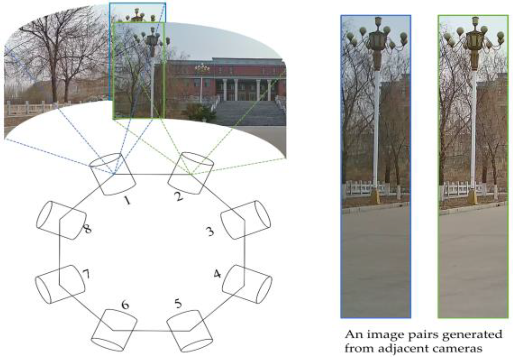
In contrast to expensive panoramic camera systems that rely on professional cameras, a low-cost panoramic camera system is developed by a combination of eight low-cost web cameras in this paper.
(2)
An inverse rigorous panoramic imaging model is derived completely based on the pre-calibration of the inner orientation elements, distortion parameters of each camera, and the relative orientation relationships between cameras.
(3)
A scheme is proposed to estimate object-distance information within a surrounding scene. By expending the traditional Vertical Line Locus (VLL) object-based image matching algorithm [29], a panoramic Vertical Line Locus algorithm called PVLL is proposed to derive the optimized object-distance grids.
The rest of the paper is organized as follows: Section 2 introduces a panoramic camera system integrated with multiple cameras, developed by our team. Moreover, the inverse rigorous panoramic imaging model is derived completely based on pre-calibration of the panoramic camera system. In Section 3, we propose the panoramic generation method, with a specific focus on the object-distance estimation algorithm. The detailed experiment and analysis are provided in Section 4. Section 5 summarizes this research and provides recommendations related to future research works.

2. Related Work

2.1. Feature Point-Based Panoramic Imaging Method

For a set of overlapping images acquired with a multi-camera panoramic system, it is possible to generate a panoramic image relying on feature point-based methods. In the approach, the SIFT feature points are detected and matched on the overlapping regions of each pair of images from adjacent cameras [19,20,21]. Assuming that the scene is flat, the homographic estimations [22,23] are performed based on corresponding feature-points for each two adjacent cameras. At this point, all the transformations are modified relative to the master image, which is required for the generation of the panoramic images. The panoramic imaging approach is an extension of feature-based image registration and stitching of a single pair of images, which can be applied in scenes with rich texture features. However, this method heavily depends on achieving a sufficient distribution and accurate matching of feature points, as well as requiring substantial overlap between adjacent cameras. Additionally, it requires less variation in object-distance information from the surroundings, as the homographic transformation only exists between two planes.

2.2. Traditional Panoramic Imaging Model Based Method

The panoramic imaging model-based method, which departs from the feature-based method, requires accurate inner orientation elements of each camera and the relative orientation parameters between cameras to develop an accurate projection transformation relationship from the coordinate system of a perspective camera to that of the virtual panoramic camera.
Traditionally, the ideal panoramic spherical and cylindrical imaging model are formulated by disregarding the eccentric error between the center of the virtual panorama camera and that of an actual camera [26,27]. The rigorous panoramic imaging model is further proposed by incorporating the eccentric vectors among the optical centers of the cameras into the panoramic imaging model. The rigorous model is theoretically more accurate than the ideal model [25]. However, both the ideal and rigorous panoramic imaging models are developed without consideration of the varied object-distance information in a scene. Lin [30] tries to estimate a unified cylinder projection radius based on a loss function to minimize the projection error of the whole scene. Due to difficulties in fitting a regular cylinder surface for a real environment, stitching errors may still appear where the projection radius departs from the object-distance information. In addition, traditional panoramic models describe the transformation relationship from perspective imaging to panoramic imaging, which can easily lead to pixel aggregation or empty pixels in panoramic images.
Aiming at accurate and seamless panoramic imaging with a multi-camera system, an inverse panoramic imaging method is proposed by estimation of object-distance information of the surrounding scene, construction of the inverse transformation model and introduction of the eccentric errors.

3. Proposed Method

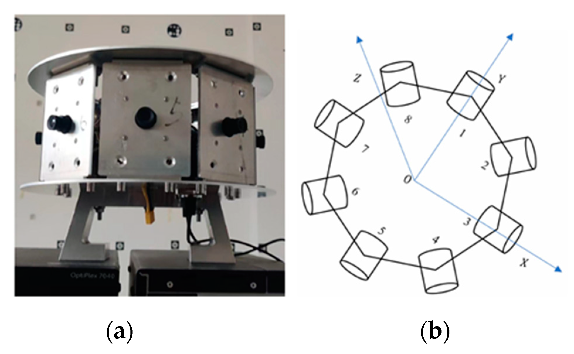
3.1. Overview of the Panoramic System

In this paper, we have designed a panoramic camera system that incorporates eight low-cost, high-definition web cameras mounted on an octagonal platform, as illustrated in Figure 1a. The panoramic camera system has a  360 °  view field in the horizontal direction and  45 °  view field in the vertical direction. Each camera has 2952 × 1944 pixels and is equipped with a lens of 5 mm focal length, with  60 °  view field in the horizontal direction and  45 °  view field in the vertical direction.

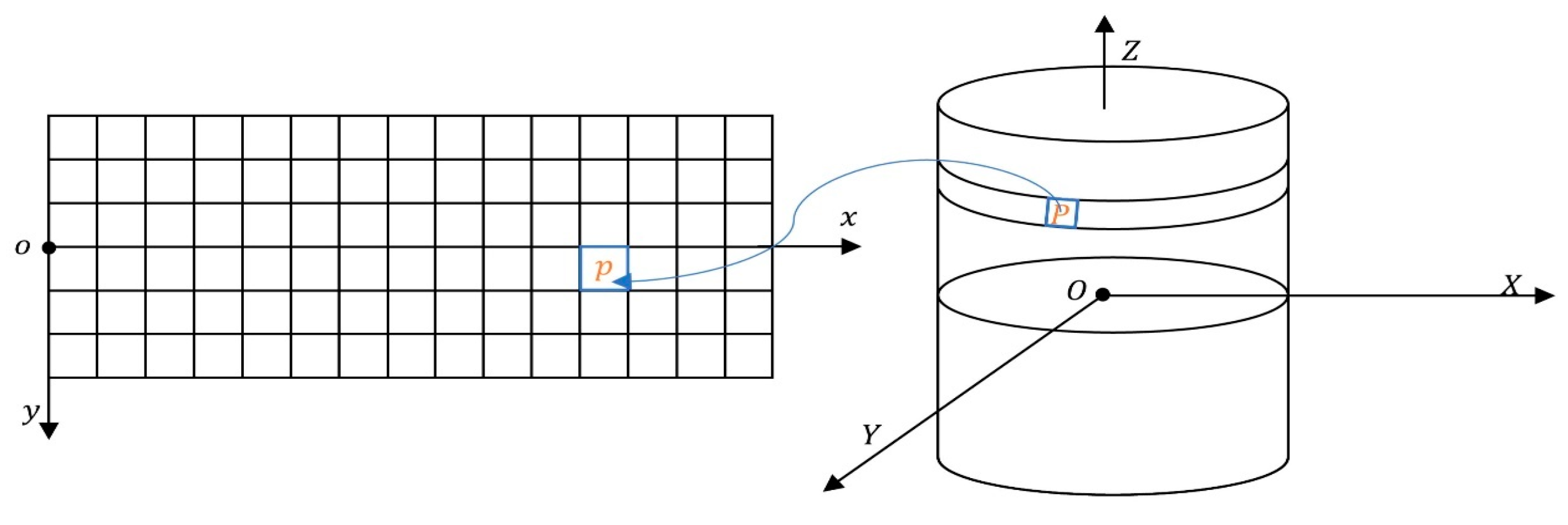
3.2. Proposed Inverse Panoramic Imaging Model

3.2.1. Relative Orientation between a Camera and the Panoramic Camera

According to the structure of our designed system in Figure 1, the relative orientation relationships are derived in this section. Let  C i  be the optical central point of the  i t h  camera  ( i = 1 , 2 , , 8 ) , and  C i x y z  be the image space coordinate system. The panoramic cylindrical coordinate system is defined with its origin, set as O, located at the optical center shared by all cameras. The X, Y, and Z axes of this coordinate system are aligned parallel to the y, z, and x axes, respectively, of the image space coordinate system of the first camera, as illustrated in Figure 2. Thus, the orientation rotation matrix of the  i t h  camera can be derived by Equation (1).
R i = R i Λ
where  R i  is the rotation matrix from the panoramic cylindrical coordinate system to the camera coordinate system of the  i t h  camera.  R i  is the rotation matrix from the image space coordinate system of the first camera to that of the  i t h  camera, and  Λ  is a matrix,  Λ = 1 0 0 0 0 1 0 1 0 .
In addition, it is required to calculate the relative translation vector, set as  t i , between point O and point  C i  by Equation (2).
t i = i = 1 8 R i T t i 8 R i T t i
where  t i  is the pre-calibrated relative translation vector between the optical centre point of the first camera and that of the  i t h  camera.
Aiming at removing empty pixels and pixel aggregation in virtual panoramas, an inverse panoramic imaging model is further derived in this paper.

3.2.2. Inverse Panoramic Imaging Model

Let point  P  be projected on the cylinder surface, which is captured from the  i t h  camera and mapped to point  p i  in the real image  I i . The ideal image model can be derived based on a traditional collinear equation [11], as shown in Equation (3).
u i , p v i , p 1 = λ K i R i X P X i Y P Y i Z P Z i
where  λ  is the scale factor,  K i  is the inner orientation matrix of the  i t h  camera,  u i , p , v i , p  is the undistorted coordinate of  p i [ X P Y P Z P ] T  and  [ X i Y i Z i ] T  are the cylindrical coordinates of points  P  and  C i , respectively. In addition, the cylindrical projection point  P  satisfies Equation (4):
X P 2 + Y P 2 = r 2
where  r  represents the cylindrical radius.
The panoramic cylindrical surface is unwrapped onto a panoramic plane, with  o x y  being taken as its panoramic planar coordinate system, as illustrated in Figure 2. Point P is mapped to point  p  based on Equation (5), which is derived from Equations (3) and (4).
u i , p v i , p 1 = λ K i R i r s i n π x p L X i r c o s π x p L Y i 2 π r / L W / 2 y p Z i
where  x p , y p  stand for the coordinate of point  p  in the virtual image in the x- and y- directions, respectively.

3.3. Object-Distance Estimation Algorithm

A panoramic image generated from the multi-camera system can be divided into the overlapping areas projected from two adjacent cameras and non-overlapping areas projected from only one camera, as shown in Figure 3. Traditionally, the panoramic images can be generated with a single projection radius  r  under the assumption of a constant object-distance in the surroundings. While projection errors may occur due to variations in object-distance information, these errors are typically not easily discernible in the non-overlapping areas of a virtual panoramic image. However, stitching seams and geometric inconsistencies may become apparent and visible in the overlapping regions of a panoramic image. For example, the object points  Q 1 Q 2 , and  Q 3  are respectively projected onto distinct overlapping regions of a virtual cylinder surface with the radius  r  by individual cameras, as shown in Figure 4. In this case, the displacements between corresponding projection points  Q k , L  and  Q k , R  (k = 1, 2, 3) from the same object point are contingent upon the difference between the object-distance  d k  and the radius  r .
In this case, a crucial challenge lies in estimating the object-distance information of the surrounding scene captured within the overlapping regions of each pair of adjacent cameras. To solve the problem, this paper presents a three-step algorithm for determining object-distance information in the surroundings to create seamless panoramic images.
In the first step, we estimate the scope of overlapping regions in a panoramic image and generate pyramid grids. In the second step, object-distance information is determined using an improved VLL (Vertical Locus Line Method for the surroundings captured in the overlapping regions of the panoramic image). Finally, we employ an interpolation method to estimate object-distance information for each non-overlapping region.

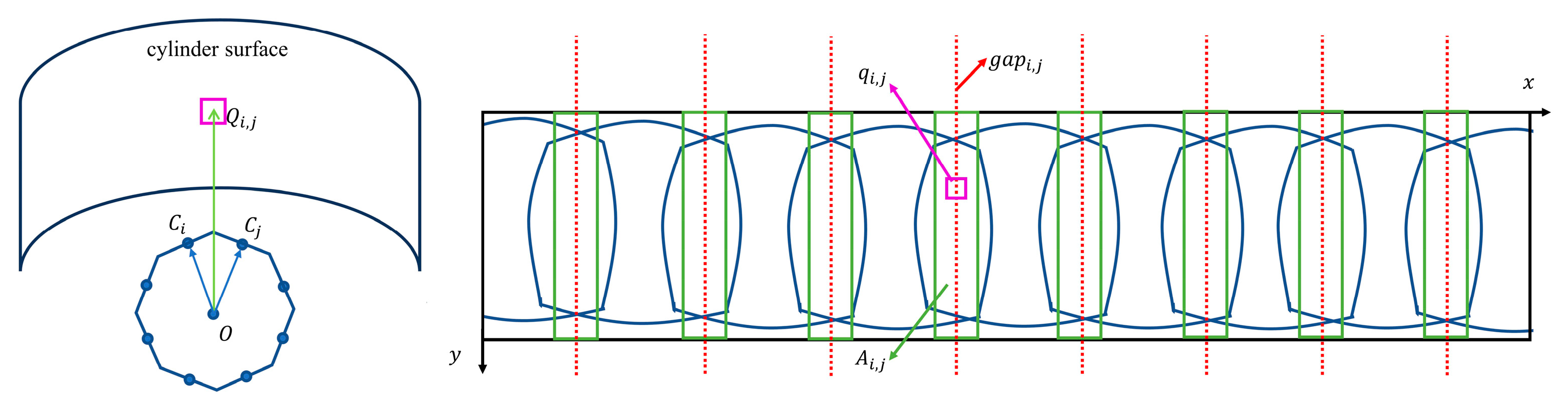
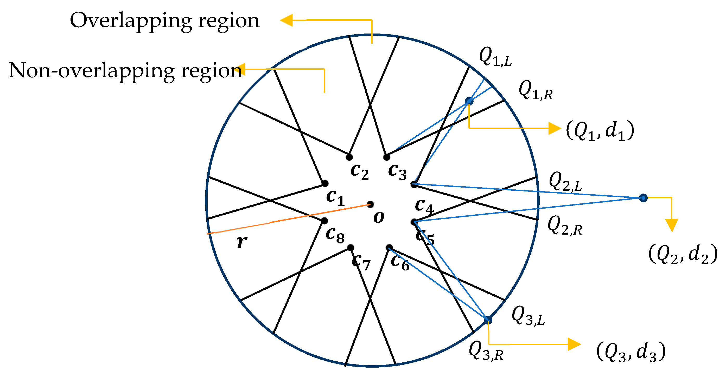
3.3.1. Generation Algorithm of Pyramid Grids in Overlapping Regions

In this paper, each overlapping region of a panoramic image is first generated around the central line, which is defined as the angular bisector vector between two adjacent cameras.
As illustrated in Figure 3, let  Q i j  be a point on the cylinder surface, and  O Q i j  be the vector in the same direction as the angular bisector vector between  O C i  and  O Q j . The vector  O Q i j  can be derived by Equation (6). In addition,  Q i j  is then projected onto the point  q i j  within the panoramic image. The  x -coordinate  g a p i , j  of  q i j  can be computed by Equation (7). Further, the overlapping region  A i , j , with a width of  w  and  g a p i , j  setting as the central line, is generated, expanding  x i , j  pixels away from the y-axis.
O Q i , j = λ ( O C i O C i + O C j O C j )
x i , j = W 2 π arctan ( Y i , j X i , j )
In Equations (6) and (7),  O Q i j  is set as  [ X i , j Y i , j Z i , j   ] T ,  where  X i , j , Y i , j , Z i , j    represent the  X Y  and  Z  cylindrical coordinates of point  Q i j , respectively.  λ  is the scale factor, and  x i , j  is the x-coordinate of  q i j  in the panoramic image coordinate system.  W  is the width of the virtual panorama image. The parameters  i  and  j  take on the following values:  i = 1 , 2 , 3 , , 8 ,   j = 1 , 2 , 3 , 4 , , 8 .
By adopting a strategy of progressive refinement from coarse to fine, eight object-distance maps (ODMs) are constructed for each overlapping region of a virtual panoramic image. Assuming that the resolution of  A i , j  is  W  pixels by  H  pixels, a pyramid grid is established with  N  levels for each overlapping region as follows:
First, the  N  th level of the pyramid grid is segmented into cells with dimensions  W 2 N  by  H 2 N . Each cell at this level has a resolution of  2 N  pixels by  2 N  pixels, and the pixels within the cell share the same object-distance.Second, the pyramid grids from the  ( N 1 ) t h  to the top layer of the  t t h  level can be generated in a coarse-to-fine manner. At the  l t h  level, the grid has dimensions of  W 2 l  by  H 2 l  cells, and each cell has a resolution of (of  2 l W 2 N  pixels by  2 l W 2 N  pixels), where  l  takes values from N−1 down to  t .
Considering the balance of efficiency and accuracy, the parameters  W H N  and  t  are given empirical values, namely 256, 2560, 8, and 4, respectively.

3.3.2. Estimation of Object-Distance Pyramid Maps in Overlapping Regions
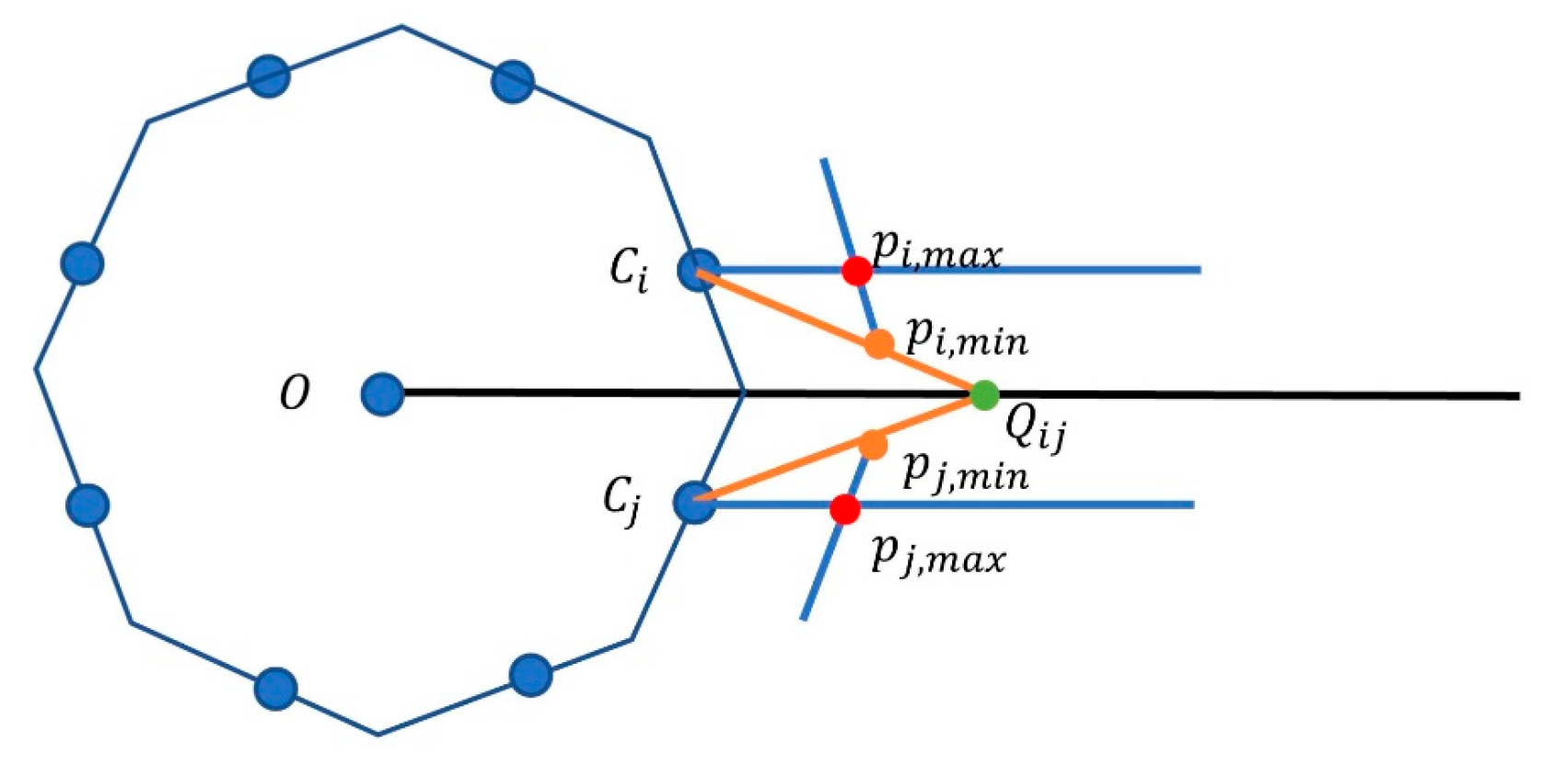
The traditional object space-based matching method, which was called the Vertical Locus Line Method (VLL) [29], is often used to estimate depth information by accurately matching a pair of image patches without directly calculating the three-dimensional computation for object points. Previous approaches of the VLL matching algorithm are mainly constrained to perspective projection images and require priori depth information. As a result, the VLL matching algorithm may exhibit reduced efficiency or failure due to the absence of prior object-space information. This paper proposes the Panoramic Vertical Locus Line (PVLL) matching algorithm to estimate the object-distance of panoramic surroundings based on pyramid grids ranging from coarse to fine.
(1)
Estimation of Candidate Object-Distance
An object-distance set is estimated priorly to increase the efficiency of the search-space size for PVLL matching. Supposing that the minimum and maximum object-distances of surroundings are defined as  r m i n  and  , the reprojected locations of the object point  Q i j  (where  r m i n r ) will be restricted between point  p i , m i n  to point  p i , m a x  in image  I i , and between point  p j , m i n  and point  p j , m i n  in  I j , respectively, as shown in Figure 5.
Given the object-distance of point  Q i j  is  r , the horizontal displacement  h ( r )  between the projection location and point  p i , m a x  in image  I i  can be approximately computed by Equation (8).
h r L α arccos r d cos π 2 n d 2 + r 2 2 d r cos π 2 n
where  L  is the width of the image of the sub-camera,  α  is the horizontal field of view of the sub-camera, and  d  is the displacement between the optical center  C i  and the origin  O  of the cylindrical projection coordinate system.
Further, the list of candidate object-distances, set as  r l i s t = r 0 , r 1 , r 2 , , r T 1 , can be acquired using Algorithm 1 based on Equation (8), where  ε  is the displacement steps in pixels.
Algorithm 1: Solution of Projected Radius List
Input:  L α d n r m i n ε
Output:  r l i s t = { r 0 , r 1 , r 2 , , r T 1 }
1:  r r m i n + 1 r 0 r m i n m 1
2:  h L α a r c c o s ( r d cos ( π 2 n ) d 2 + r 2 2 d r cos ( π 2 n ) )
3: repeat
4:   h b L α a r c c o s ( r d cos ( π 2 n ) d 2 + r 2 2 d r cos ( π 2 n ) )
5:  if  a b s h h b > ε  then
6:     r m r , m m + 1 h h b
7:  end if
8:   r r + 1
9: until  h < ε
Output:  { r 0 , r 1 , r 2 , , r T 1 }
As the object-distance changes continuously from  r 0  to  r T 1 , the back-projection location of an object point imaged in an overlapping region approximately moves along a straight line by ε pixels in a real image, as shown in Figure 6. Here,  ε  has been set to 1 pixel to provide an optimal balance between the object-distance resolution and computational efficiency.
(2)
Panoramic Vertical Line Locus Algorithm
Definition 1. 
The corresponding image patches are represented as  I i G i , j l φ , ψ , R i , j l φ , ψ  and  I j G i , j l ( φ , ψ ) , R i , j l φ , ψ  at the  l th pyramid level, respectively, where  G i , j l φ , ψ  be the grid cell located at the  φ t h  row and  ψ t h  column of the pyramid grid in  A i , j ,  r R i , j l φ , ψ  be the object-distance in this cell,  R i , j l φ , ψ  denotes the index of  r R i , j l φ , ψ  in  r l i s t , and here  l  takes values from N down to t.
We can assume that the pixel point  a  in the grid cell is reprojected to locations of  ( u a , i , v a , i )  in image  I i  and  ( u a , j , v a , j )  in image  I j  using  r R i , j l φ , ψ  as the cylinder radius based on Equation (9) derived from Equation (5), respectively. Thus, a pair of grey values can be acquired based on the grey bilinear interpolation algorithm using four-pixel points around the points  ( u a , i , v a , i )  and  ( u a , j , v a , j ) , respectively. In this way,  I i G i , j l φ , ψ , R i , j l φ , ψ  and  I j G i , j l ( φ , ψ ) , R i , j l φ , ψ  can be generated with a resolution of  2 l  pixels by  2 l  pixels, respectively.
u a , i v a , i 1 = s i K i R i r R i , j l φ , ψ s i n π x a L X i r R i , j l φ , ψ c o s π x a L Y i 2 π r R i , j l φ , ψ L W 2 y a Z i ,   u a , j v a , j 1 = s j K j R j r R i , j l φ , ψ s i n π x a L X j r R i , j l φ , ψ c o s π x a L Y j 2 π r R i , j l φ , ψ L W 2 y a Z j
Definition 2. 
Let     N C C ( G i , j l φ , ψ , R i , j l φ , ψ )  be the Normalized Cross-Correlation image matching parameter between image blocks  I i G i , j l φ , ψ , R i , j l φ , ψ  and  I j G i , j l φ , ψ , R i , j l φ , ψ .
The value of    N C C ( G i , j l φ , ψ , R i , j l φ , ψ )  can be computed by Equation (10).
  N C C ( G i , j l φ , ψ , R i , j l φ , ψ ) = x = 0 s y = 0 s g i x , y g i ¯ ( g j ( x , y ) g j ¯ ) x = 0 s y = 0 s g i x , y g i ¯ 2 x = 0 s y = 0 s ( g j ( x , y ) g j ¯ ) 2
where  g i x , y  and  g j x , y  are the greyscales located at  x , y  in the image block  I i G i , j l φ , ψ , R i , j l φ , ψ  and  I j G i , j l φ , ψ , R i , j l φ , ψ , respectively.  g i ¯ g j ¯  are the average grey values of the two image patches, respectively, where  s = 2 l .
Object-distance estimation based on the above definitions: Different from previous VLL-based methods that predict object-distance information directly, the proposed PVLL object-space matching method computes the index of the required object-distance in the estimated list  r l i s t  from coarse to fine.
First, an objective function  E i , j  is generated at the  N t h  pyramid layer in the overlapping region  A i , j  to optimize the object-distance information of each grid cell.  E i , j  is proposed based on the similarity of the image intensity between a pair of corresponding image patches and the smoothness of object-distance between adjacent grid cells, as depicted in Equation (11).
E i , j = ρ 1 φ = 0 Φ 1 N C C ( G i , j N φ , 0 , R i , j N φ , 0 ) Φ + ρ 2 φ = 1 Φ 1 R i , j N φ , 0 R i , j N φ 1 , 0 ) T
where  ρ 1  and  ρ 2  are the weight coefficients of similarity and smoothness, respectively.  E i , j  is the objective function;  Φ 1  is the count of rows for the  N t h  pyramid gird. Further, a group of optimum object-distance indices, denoted by  R i , j N 0,0 , R i , j N 1,0 , , R i , j N Φ 1,0 , can be estimated by iteratively solving Equation (12) using a dynamic programming algorithm [31]. Then, an object-distance map (ODM) is generated for the overlapping region  A i , j  at a resolution of  w 2 N  by  H 2 N  in the  N t h  level, based on the optimal index parameters. Additionally, a corresponding index map is also created.
R i , j N 0,0 , R i , j N 1,0 , , R i , j N Φ 1,0 = argmax R i , j N 0,0 , R i , j N 1,0 , , R i , j N Φ 1,0 E i , j
Second, from the  ( N 1 ) t h  to the top pyramid layer  t t h , we employ an iterative image matching procedure as follows:
For each grid cell  G i , j l φ , ψ , a group of candidate object-distances  r R i , j l φ , ψ + k ζ | k = 0 , ± 1 , , ± K ; ζ = 1 K  are determined by Equation (13).
r R i , j l φ , ψ + k ζ = r R i , j l φ , ψ + k ζ + k ζ r R i , j l φ , ψ + k ζ r R i , j l φ , ψ + k ζ
where  R i , j l φ , ψ  are set as the optimum estimation of the object-distance index of the grid cell at the  φ 2  row and  ψ 2  column in the previous layer, where  l  takes values from N − 1 down to t.
Then, these candidates are chosen with regular index increments ζ, changing between the minimum object-distance  r R i , j l φ , ψ 1  and the maximum object-distance  r R i , j l φ , ψ + 1 . The value of K has been determined through experimentation to achieve the optimal balance between candidate performance and computational load. The optimum value of the parameter k, represented by  k , is therefore extracted by searching the maximum NCC value using Equation (14), which is derived from Equations (9) and (10).
k = argmax k N C C G i , j N φ , ψ , R i , j l φ , ψ + k ζ | k = 0 , ± 1 , , ± K
where  N C C G i , j l φ , ψ , R i , j l φ , ψ + k ζ  is computed by a pair of corresponding image patches based on Equation (10), and the image patches are generated by reprojection of each pixel in  G i , j l φ , ψ  onto  I i  and  I j  based on Equation (9), respectively.
Therefore, the optimal object-distance is set as  r R i , j l φ , ψ + k ζ  for the grid cell  G i , j l φ , ψ .
In this way, the resolution and structure of the object-distance maps, along with the index maps, are updated with the optimum object-distance for each grid cell, until reaching the top pyramid level.

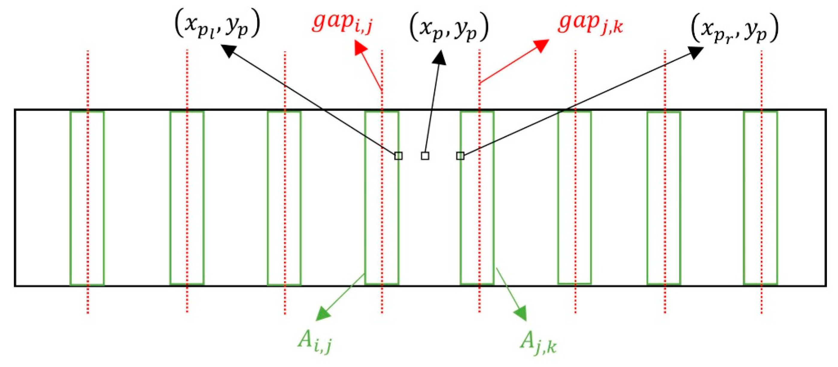
3.4. Object-Distance Interpolation Method in the Non-Overlapping Regions

An interpolation method is adopted to derive object-distance information in the non-overlapping regions. For a pixel point  p x p , y p  located in the non-overlapping region between two overlapping regions  A i , j  and  A j , k , its object-distance can be interpolated from the known object-distance information of two points  p l x p l , y p  and  p r x p r , y p  using Equation(15), as shown in Figure 7.
r t x p , y p = x p r x p x p r x p l w x p x p l x p r x p l w r t x p l , y p r t x p r , y p
where  r t x p , y p ,   r t x p l , y p , and  r t x p r , y p  are the object-distances of pixel point  p p l  and  p r , respectively. The object-distance information can be calculated using the object-distance maps in the top-level of the aforementioned pyramid grids.
The values of  x p l  and  x p r  are determined by  x j , k L w 2  and  x i , j L + w 2 , respectively, where  w  represents the width of an overlapping region. In this context,  i  takes values from 1 to 7, j takes values from 2 to 7, and k takes values from 3 to 8, including 0. The parameters of  x i , j L  and  x j , k L  represent the displacements of the centre lines  g a p i , j  and  g a p j , k  from the y-axis of the panoramic image system, respectively. In the same way, the object-distances can be estimated for all the pixel points in the non-overlapping regions.
Finally, a panoramic image can be generated based on Equation (9) with the estimated object-distance information on the overlapping regions and non-overlapping regions.

4. Experimental Results

In this section, we conducted detailed experiments and carried out a comprehensive analysis for generating panoramic images using the panoramic camera system developed in this paper. The algorithm for the panorama generation was implemented in C++ using the OpenCV 4.3 development package on a computer equipped with an AMD Ryzen 7 5800H, 3.2 GHz processor, and 16 GB main memory.

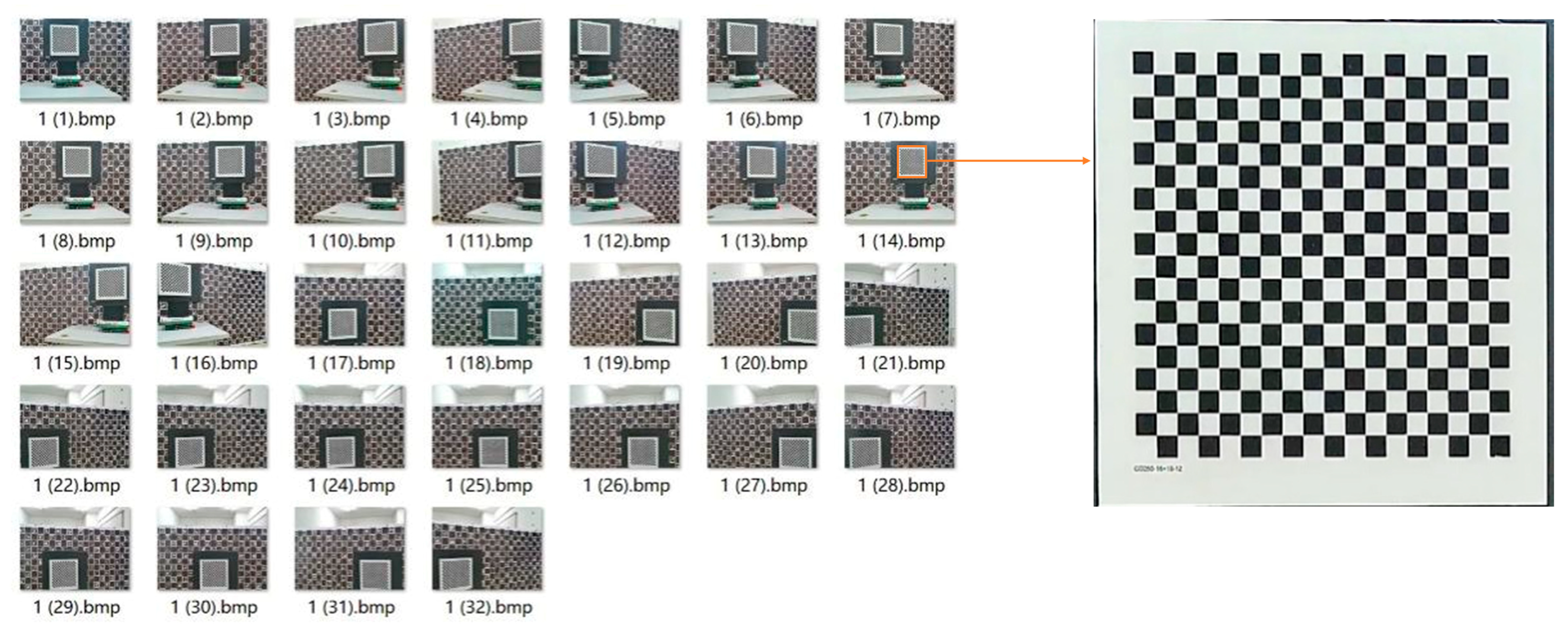
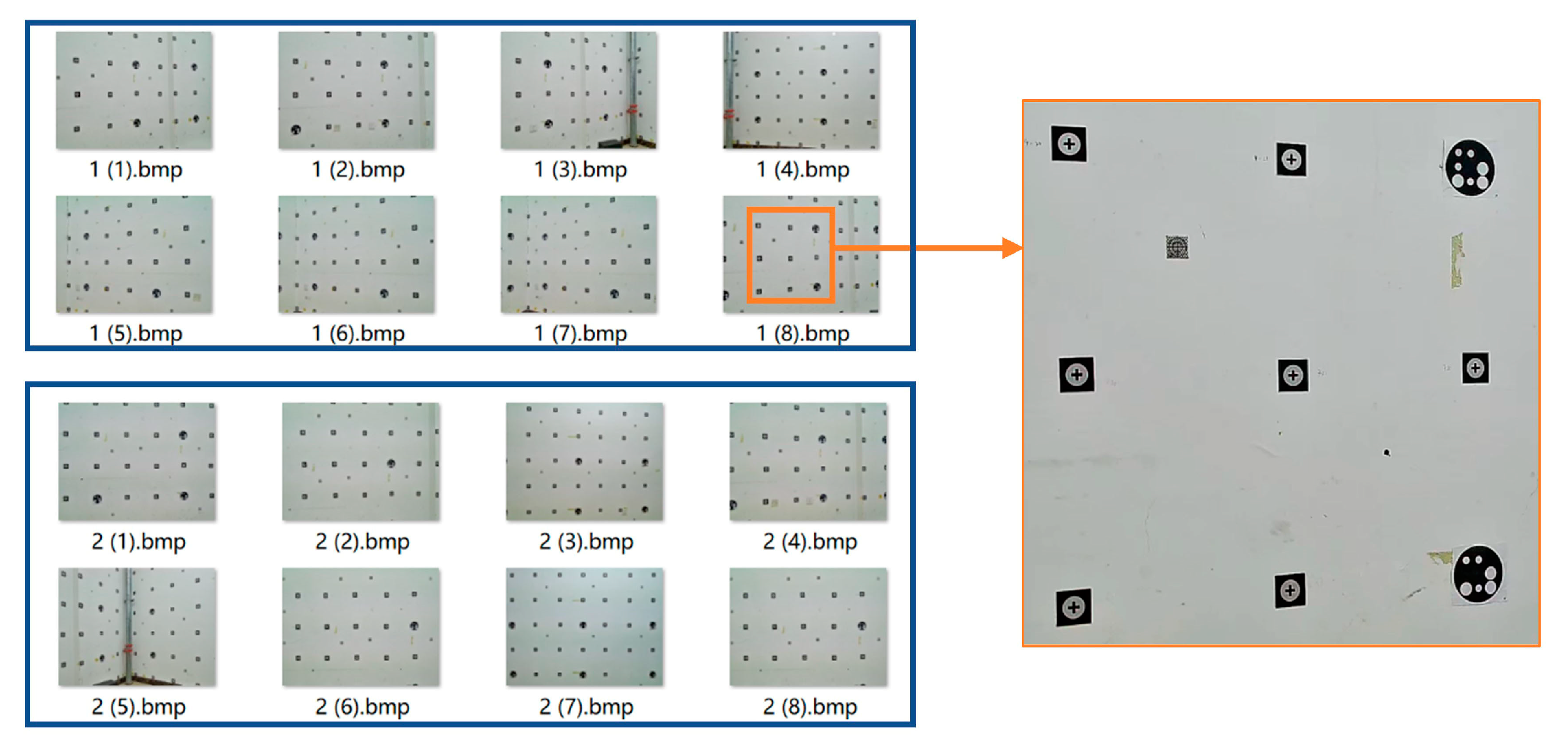
4.1. Calibration of the Panoramic Camera

In this paper, the multi-camera system was fixed on an octagonal structure to ensure the constant relationships among cameras. A two-step method is conducted to calibrate the internal parameters of each camera and ROPs (relative orientation parameters). Firstly, more than 30 images of a high-precision chessboard were taken with each camera at different poses and positions, as shown in Figure 8. The inner orientation elements and the distortion coefficients of each camera were calibrated by Zhang’s calibration method [32]. The interior orientation elements for each camera are shown in Table 1.
Secondly, a professional three-dimensional calibrate field was used to calibrate the ROPs. Ten groups of images were taken at different poses and positions, where each group of images are captured at the same time, as shown in Figure 9.
The external parameters of the  i t h  camera at the  k t h  exposure epoch were calibrated based on the traditional PnP method [33]. Let the first camera be the master camera, while the other seven cameras are slave cameras. Let  R i , k  and  t i , k  represent the rotation matrix and position of the  i t h  camera relative to the world coordinate system at the kth exposure epoch, where k = 1, 2, …, K. In this experiment, the value of K is 10. The ROPs between the master camera and any slave camera can be computed by Equations (16) and (17). The optimum relative orientation parameters can be seen in Table 2.
R i = argmin R i S O 3 k = 0 K R i R 1 , k ( R i , k ) T
t i = 1 K k = 0 K ( t i , k R 1 , k t i , k )

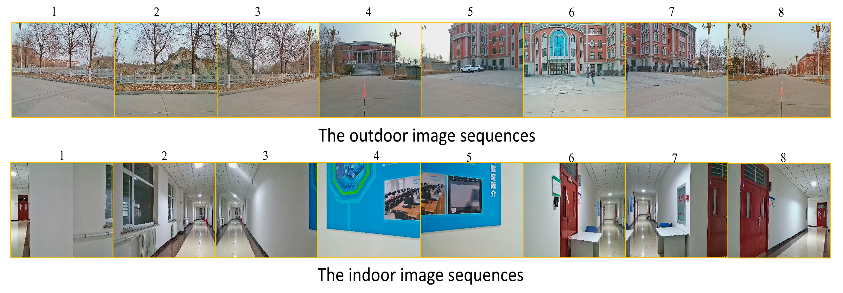
4.2. Visualized Analysis

We conducted a performance comparison of our proposed method (Method C) with AutoStitch [19] (Method A) and the traditional cylindrical panoramic stitching method [32] (Method B) using both indoor and outdoor scenes, as depicted in Figure 10.
Figure 11 displayed the panoramas for an outdoor scene. In Figure 11a, stitching truncation (resulting in structural discontinuity) can be observed in the roadway, highlighted with an orange box. In Figure 11b, the repetition of road lamps is evident, highlighted with the blue box. In contrast, the panoramic image generated by our algorithm (Method C) demonstrates visual consistency within the highlighted overlapping regions, as depicted in Figure 11c.
Figure 12 displays the panoramas for an indoor scene. In Figure 12a, more truncation and ghosting of the ceiling can be noticed, as highlighted with the orange box. Furthermore, the panoramic image shows significant gaps, particularly in areas with a low-texture environment lacking distinct feature points, which are highlighted with red boxes in the overlapping regions. In Figure 12b, you can observe that the ceilings are repeatedly generated, highlighted with an orange box. In contrast, the panoramic image generated by our algorithm (Method C) is complete and seamless in the area highlighted within the same orange box, as depicted in Figure 12c.
Therefore, it becomes evident that when compared to Method A and Method B, our approach (Method C) maintains visual consistency in both indoor and outdoor scenes and effectively eliminates stitching gaps, especially in scenes with low-texture regions.

4.3. Quantitative Analysis

Our quantitative analysis was conducted based on the following steps:
(1)
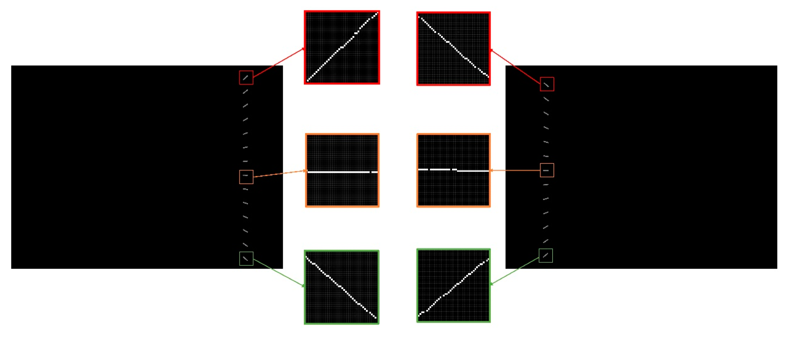
Each pixel within every overlapping region of a panoramic image was individually projected onto two overlapping original images captured by adjacent cameras, and the grayscale value of the projection points was obtained. In this way, two panoramic image patches were generated for each overlapping region, as shown in Figure 13.
(2)
The SIFT [34] feature points were then extracted and matched for each pair of panoramic image patches. The average Euclidean distance was then computed between corresponding feature points in every pair of panoramic image patches. In addition, the parameters of the Structural Similarity Index (SSIM) [31], Peak Signal-to-Noise Ratio (PSNR) [35], Normalized Cross-Correlation (NCC) coefficients, and Stitched Image Quality Evaluator (SIQE) [36] were determined to quantify the dissimilarities between each pair of panoramic image patches. The Root Mean Square Error (RMSE), average SSIM, average PSNR, and average NCC are further computed based on the average Euclidean distances, SSIM values, PSNR values, NCC coefficients, and SIQE respectively, obtained from the dataset of 160 panoramas.
(3)
Moreover, using the open-source library functions [37], we calculated the Stitched Panoramic Image Quality Assessment (SPIQA) [38] parameter for each group of images from eight cameras and the corresponding generated panoramic images. Then, we calculated the average of 160 SPIQAs.
Figure 13. An image pair generated from adjacent cameras.
Applsci 13 12309 g013
This comprehensive analysis allowed us to evaluate the quality and dissimilarities based on various metrics and parameters, encompassing both structural and pixel-wise differences, as depicted in Table 3.
Because the object distance in the outdoor scene is significantly larger than the eccentric distance between the optical center of a sub-camera and that of the virtual panoramic camera, the stitching accuracy of a panorama is less affected by inconsistencies in object-distance information within the surrounding scene. Thus, the proposed method only has a small improvement compared to Methods A and B. However, due to the restricted range of object-distances in indoor scenes, the eccentricity errors between cameras cannot be disregarded and may lead to substantial stitching errors when employing both Method A and Method B, especially when there are variations in the object-distance. Our proposed algorithm generates a panorama by utilizing the multiple projection radiuses from the estimation of object-distance information, which demonstrates far higher accuracy than Method A and B. In addition, it can be seen clearly that the stitching time of Method C is much higher than that of Method A and B.

5. Conclusions and Future Work

Aiming at remote sensing and mapping applications, we have designed a low-cost  360 °  image acquisition system through the integration of eight web cameras, which were securely mounted on a circular rig. To solve the mosaicking problems caused by inconstant and inconsistent object-distance information within a scene, a panoramic image generation algorithm was proposed to improve the existing direct mono-cylinder imaging model. The key aspect of the algorithm is the Panoramic Vertical Line Locus matching algorithm called the PVLL algorithm, which is proposed by extending the traditional VLL algorithm. Moreover, the object-distance grids can be generated based on the PVLL algorithm in the overlapping regions of a panorama. Thus, the panorama can be generated by utilizing the multiple projection radiuses from the estimation of object-distance information. The experiments show that the proposed imaging method successfully improves the stitching accuracy and visual effects of virtual panoramas.
In summary, this paper discusses the problems of geometric mosaicking errors in multi-camera panoramic systems and conducts research on the combination of accurate calibration, depth estimation, and post-processing techniques to ensure a seamless and accurate panoramic view, despite variations in object distances and eccentric errors between camera optical centers. The method described in this paper is suitable for a multi-camera system with an annular structure, and we plan to extend it to a panoramic system with a 720-degree spherical design in our future work for ground remote sensing applications in both outdoor and indoor environments.

Author Contributions

Methodology, H.C. and Z.Z.; Software, Z.Z. and F.Z.; Writing—original draft, H.C. and Z.Z.; Writing—review and editing, H.C. and Z.Z.; Visualization, Z.Z.; Translation Check, F.Z.; Project administration, H.C.; Funding acquisition, H.C. All authors have read and agreed to the published version of the manuscript.

Funding

This work was supported by the Liaoning Provincial Science and Technology Mission Plan, Department of Liaoning Province, China (No. 2023020569-JH5/104); the key project of the Department of Education in Liaoning Province, China (No. 2023003); and the National Natural Science Foundation of China (No. 41371425).

Institutional Review Board Statement

Not applicable.

Informed Consent Statement

Not applicable.

Data Availability Statement

Data presented in this study are available on request from the corresponding author. The data are not publicly available due to privacy (General Data Protection Regulation possible issues).

Conflicts of Interest

The authors declare no conflict of interest.

References

  1. Kao, S.T.; Ho, M.T. Ball-Catching System Using Image Processing and an Omni-Directional Wheeled Mobile Robot. Sensors 2021, 21, 3208. [Google Scholar] [CrossRef] [PubMed]
  2. Wu, F.; Song, H.; Dai, Z.; Wang, W.; Li, J. Multi-camera traffic scene mosaic based on camera calibration. IET Comput. Vis. 2021, 15, 47–59. [Google Scholar] [CrossRef]
  3. Krishnakumar, K.; Gandhi, S.I. Video stitching using interacting multiple model based feature tracking. Multimed. Tools Appl. 2018, 78, 1375–1397. [Google Scholar] [CrossRef]
  4. Qu, Z.; Wang, T.; An, S.; Liu, L. Image seamless stitching and straightening based on the image block. IET Image Process. 2018, 12, 1361–1369. [Google Scholar] [CrossRef]
  5. Li, L.; Yao, J.; Xie, R.; Xia, M.; Zhang, W. A Unified Framework for Street-View Panorama Stitching. Sensors 2016, 17, 1. [Google Scholar] [CrossRef]
  6. Wenbo, J.; Xuefeng, G.; Bingkun, H.; Shitao, L.; Hongyang, Y. Expansion of Conical Catadioptric Panoramic Image of Inner Surface of Cylindrical Objects. Acta Opt. Sin. 2021, 41, 0311002. [Google Scholar] [CrossRef]
  7. Amani, A.; Bai, J.; Huang, X. Dual-view catadioptric panoramic system based on even aspheric elements. Appl. Opt. 2020, 59, 7630. [Google Scholar] [CrossRef]
  8. Baskurt, D.O.; Bastanlar, Y.; Cetin, Y.Y. Catadioptric hyperspectral imaging, an unmixing approach. IET Comput. Vis. 2020, 14, 493–504. [Google Scholar] [CrossRef]
  9. Ko, Y.J.; Yi, S.Y. Catadioptric Imaging System with a Hybrid Hyperbolic Reflector for Vehicle Around-View Monitoring. J. Math. Imaging Vis. 2017, 60, 503–511. [Google Scholar] [CrossRef]
  10. Khoramshahi, E.; Campos, M.; Tommaselli, A.; Vilijanen, N.; Mielonen, T.; Kaartinen, H.; Kukko, A.; Honkavaara, E. Accurate Calibration Scheme for a Multi-Camera Mobile Mapping System. Remote Sens. 2019, 11, 2778. [Google Scholar] [CrossRef]
  11. Zhang, Y.; Huang, F. Panoramic Visual SLAM Technology for Spherical Images. Sensors 2021, 21, 705. [Google Scholar] [CrossRef] [PubMed]
  12. Buyuksalih, G.; Baskaraca, P.; Bayburt, S.; Buyuksalih, I.; Rahman, A.A. 3D city modelling of istanbul based on lidar 333 data and panoramic images—Issues and challenges. Int. Arch. Photogramm. Remote Sens. Spat. Inf. Sci. 2019, XLII-4/W12, 51–60. [Google Scholar] [CrossRef]
  13. Nespeca, R. Towards a 3D digital model for management and fruition of Ducal Palace at Urbino. An integrated survey with mobile mapping. Sci. Res. Inf. Technol. 2019, 8, 1–14. [Google Scholar] [CrossRef]
  14. Afifi, A.; Takada, C.; Yoshimura, Y.; Nakaguchi, T. Real-Time Expanded Field-of-View for Minimally Invasive Surgery Using Multi-Camera Visual Simultaneous Localization and Mapping. Sensors 2021, 21, 2106. [Google Scholar] [CrossRef] [PubMed]
  15. Hongxia, C.; Lijun, C.; Ning, W.; Tingting, L. Calibration Method with Implicit Constraints for Multi-View Combined Camera Using Automatic Coding of Marker Points. Chin. J. Lasers 2020, 47, 0110003. [Google Scholar] [CrossRef]
  16. Ke, X.; Huang, F.; Zhang, Y.; Tu, Z.; Song, W. 3D Scene Localization and Mapping Based on Omnidirectional SLAM. IOP Conf. Ser. Earth Environ. Sci. 2021, 783, 012143. [Google Scholar] [CrossRef]
  17. Ullah, H.; Zia, O.; Kim, J.H.; Han, K.; Lee, J.W. Automatic 360° Mono-Stereo Panorama Generation Using a Cost-Effective Multi-Camera System. Sensors 2020, 20, 3097. [Google Scholar] [CrossRef]
  18. Qu, Z.; Lin, S.P.; Ju, F.R.; Liu, L. The Improved Algorithm of Fast Panorama Stitching for Image Sequence and Reducing the Distortion Errors. Math. Probl. Eng. 2015, 2015, 428076. [Google Scholar] [CrossRef]
  19. Brown, M.; Lowe, D.G. Automatic Panoramic Image Stitching using Invariant Features. Int. J. Comput. Vis. 2006, 74, 59–73. [Google Scholar] [CrossRef]
  20. Alwan, M.G.; AL-Brazinji, S.M.; Mosslah, A.A. Automatic panoramic medical image stitching improvement based on feature-based approach. Period. Eng. Nat. Sci. 2022, 10, 155. [Google Scholar] [CrossRef]
  21. Zhu, J.T.; Gong, C.F.; Zhao, M.X.; Wang, L.; Luo, Y. Image mosaic algorithm based on pca-orb feature matching. Int. Arch. Photogramm. Remote Sens. Spat. Inf. Sci. 2020, XLII-3/W10, 83–89. [Google Scholar] [CrossRef]
  22. Hoang, V.D.; Tran, D.P.; Nhu, N.G.; Pham, T.A.; Pham, V.H. Deep Feature Extraction for Panoramic Image Stitching. In Intelligent Information and Database Systems; Springer: Berlin/Heidelberg, Germany, 2020; pp. 141–151. [Google Scholar] [CrossRef]
  23. Woo Park, K.; Shim, Y.J.; Jin Lee, M.; Ahn, H. Multi-Frame Based Homography Estimation for Video Stitching in Static Camera Environments. Sensors 2019, 20, 92. [Google Scholar] [CrossRef] [PubMed]
  24. Ji, S.; Shi, Y. Image matching and bundle adjustment using vehicle-based panoramic camera. Cehui Xuebao Acta Geod. Cartogr. Sin. 2013, 42, 94–100+107. Available online: https://api.semanticscholar.org/CorpusID:130900916 (accessed on 6 July 2021).
  25. Wang, X.; Li, D.; Zhang, G. Panoramic Stereo Imaging of a Bionic Compound-Eye Based on Binocular Vision. Sensors 2021, 21, 1944. [Google Scholar] [CrossRef] [PubMed]
  26. Sato, T.; Ikeda, S.; Yokoya, N. Extrinsic Camera Parameter Recovery from Multiple Image Sequences Captured by an Omni-Directional Multi-camera System. In Lecture Notes in Computer Science; Springer: Berlin/Heidelberg, Germany, 2004; pp. 326–340. [Google Scholar] [CrossRef]
  27. Lemaire, T.; Lacroix, S. SLAM with Panoramic Vision. J. Field Robot. 2007, 24, 91–111. [Google Scholar] [CrossRef]
  28. Shi, Y.; Ji, S.; Shi, Z.; Duan, Y.; Shibasaki, R. GPS-Supported Visual SLAM with a Rigorous Sensor Model for a Panoramic Camera in Outdoor Environments. Sensors 2012, 13, 119–136. [Google Scholar] [CrossRef]
  29. Linder, W. Digital Photogrammetry—A Practical Course; Springer: Berlin/Heidelberg, Germany, 2006. [Google Scholar]
  30. Lin, M.; Xu, G.; Ren, X.; Xu, K. Cylindrical panoramic image stitching method based on multi-cameras. In Proceedings of the 2015 IEEE International Conference on Cyber Technology in Automation, Control, and Intelligent Systems (CYBER), Shenyang, China, 8–12 June 2015; IEEE: New York, NY, USA, 2015; pp. 1091–1096. [Google Scholar] [CrossRef]
  31. Wang, Z.; Bovik, A.; Sheikh, H.; Simoncelli, E. Image quality assessment: From error visibility to structural similarity. IEEE Trans. Image Process. 2004, 13, 600–612. [Google Scholar] [CrossRef]
  32. Lepetit, V.; Moreno-Noguer, F.; Fua, P. EPnP: An Accurate O(n) Solution to the PnP Problem. Int. J. Comput. Vis. 2008, 81, 155–166. [Google Scholar] [CrossRef]
  33. Zhang, Z.Y. A flexible new technique for camera calibration. IEEE Trans. Pattern Anal. Mach. Intell. 2000, 22, 1330–1334. [Google Scholar] [CrossRef]
  34. Lowe, D.G. Distinctive Image Features from Scale-Invariant Keypoints. Int. J. Comput. Vis. 2004, 60, 91–110. [Google Scholar] [CrossRef]
  35. Horé, A.; Ziou, D. Image Quality Metrics: PSNR vs. SSIM. In Proceedings of the 2010 20th International Conference on Pattern Recognition, Istanbul, Turkey, 23–26 August 2010; pp. 2366–2369. [Google Scholar] [CrossRef]
  36. Madhusudana, P.C.; Soundararajan, R. Subjective and Objective Quality Assessment of Stitched Images for Virtual Reality. IEEE Trans. Image Process. 2019, 28, 5620–5635. [Google Scholar] [CrossRef] [PubMed]
  37. Madhusudana, P.C.; Soundararajan, R. Official Implementation of Stitched Image Quality Evaluator (SIQE). Available online: https://github.com/pavancm/Stitched-Image-Quality-Evaluator (accessed on 10 October 2023).
  38. Cheung, G.; Yang, L.; Tan, Z.; Huang, Z. A Content-aware Metric for Stitched Panoramic Image Quality Assessment. In Proceedings of the 2017 IEEE International Conference on Computer Vision Workshops (ICCVW), Venice, Italy, 22–29 October 2017; pp. 2487–2494. [Google Scholar] [CrossRef]
Figure 1. Overview of structure: (a) front view, (b) top view.
Applsci 13 12309 g001
Figure 2. Transformation from panoramic plane to cylinder.
Applsci 13 12309 g002
Figure 3. The view of the panoramic cylinder projection structure.
Applsci 13 12309 g003
Figure 4. Overlapping and non-overlapping regions in the cylinder structure.
Applsci 13 12309 g004
Figure 5. Horizontal disparity caused by different object-distances.
Applsci 13 12309 g005
Figure 6. Projection tracks from radius list.
Applsci 13 12309 g006
Figure 7. Non-overlapping regions of a panoramic image.
Applsci 13 12309 g007
Figure 8. Chessboard-images captured from one camera forcalibration.
Applsci 13 12309 g008
Figure 9. Images for computing relative orientation parameters (2 groups are displayed).
Applsci 13 12309 g009
Figure 10. The image sequences of an outdoor and indoor scene (the numbers in the picture indicate which camera numbered from 1 to 8 obtained the sub-images).
Applsci 13 12309 g010
Figure 11. Panorama of an outdoor scene. (a) Method A; (b) Method B; (c) Method C.
Applsci 13 12309 g011
Figure 12. Panorama of an indoor scene. (a) Method A; (b)Method B; (c)Method C.
Applsci 13 12309 g012
Table 1. Inner orientation elements of each camera.
Cam f x f y c x c y k 1 k 2
12.27822.42941.32590.94730.02810.0098
22.26842.41941.15351.04350.02550.0036
32.27292.42381.39741.06200.02570.0045
42.27592.42561.25231.04690.0285−0.0028
52.26012.41041.24479.42710.027180.0095
62.27442.42541.16291.08650.02530.0013
72.27612.42681.25671.00270.02530.0089
82.27312.42441.51611.06350.0306−0.0094
Table 2. Relative orientation parameters of the combined cameras.
Camα/radβ/radγ/radX/cmY/cmZ/cm
1–20.01740.7814−0.00294.80810.0295−1.9565
1–30.00911.58500.00576.5616−0.02946.6810
1–40.00462.35320.00384.81700.0683−11.5291
1–5−0.0205−3.1253−0.0108−0.21320.1015−13.3953
1–6−0.0140−2.3357−0.0212−4.75530.0871−11.2954
1–7−0.0011−1.5729−0.0238−6.81980.0953−6.7039
1–80.0105−0.7723−0.0197−4.68150.0800−1.8884
Table 3. Stitching accuracy and efficiency.
SceneMethodRMSESSIMPSNRNCCSPIQASIQETime(s)
Method A6.3341 0.5530 16.2321 0.7076 0.613160.03798.9112
OutdoorMethod B8.2422 0.5575 15.5963 0.5650 0.583954.75860.1251
Method C0.7498 0.6003 20.6502 0.8157 0.858668.48370.7539
Method A16.0997 0.7237 20.0779 0.8399 0.758251.60738.7745
IndoorMethod B34.9983 0.7579 17.4994 0.3803 0.793858.78720.1268
Method C0.9837 0.8197 27.0731 0.8593 0.904763.05230.7473
Disclaimer/Publisher’s Note: The statements, opinions and data contained in all publications are solely those of the individual author(s) and contributor(s) and not of MDPI and/or the editor(s). MDPI and/or the editor(s) disclaim responsibility for any injury to people or property resulting from any ideas, methods, instructions or products referred to in the content.

