Article

Iterative Equalization and Decoding over an Additive White Gaussian Noise Channel with ISI Using Low-Density Parity-Check Codes

by
Adriana-Maria Cuc
*,
Florin Lucian Morgoș
,
Adriana-Marcela Grava
and
Cristian Grava
*
Faculty of Electrical Engineering and Information Technology, University of Oradea, 410087 Oradea, Romania
*
Authors to whom correspondence should be addressed.
Appl. Sci. 2023, 13(22), 12294; https://doi.org/10.3390/app132212294
Submission received: 29 September 2023 / Revised: 1 November 2023 / Accepted: 10 November 2023 / Published: 14 November 2023

Abstract

:
In this article we present an iterative system of equalization and decoding to manage the intersymbol interference over an additive white Gaussian noise (AWGN) channel. Following the classic turbo equalization scheme, the proposed system consists of low-density parity-check (LDPC) coding at the transmitter side; we applied a Log maximum a posteriori probability (Log-MAP) equalizer and min-sum LDPC decoding at the receiver side. The equalizer and decoder, linked through interleaving and deinterleaving, iteratively update each other’s information. We performed the performance analysis of the proposed system, bit error rate (BER) vs. signal-to-noise ratio (SNR), considering three different impulse responses of the channel (h). Our experimental results indicated that increasing the number of iterations performed by the LDPC decoder from 10 to 20 during the iterative process of equalization and decoding leads to better outcomes. The proposed system was compared with turbo equalization and separate equalization, performed before the decoding process with minimum mean-square error (MMSE) and LDPC decoding, in terms of BER vs. SNR, considering the three different h. Based on the analyzed results, it can be concluded that the equalization performance depends on both the impulse responses of the channel and the chosen decoding and equalization method; therefore, the equalization method does not always offer good results for any h.

1. Introduction

Multipath channels involve modifying a transmitted signal into several samples of this signal. So, when quitting the intersymbol interference (ISI) channel, the receiver does not notice only the transmitted signal but an overlap of these distinct samples or replies. Turbo equalization is a digital reception method that processes data altered by multipath communication channels. Turbo equalization merges the work of an equalizer and a channel decoder in conformity with the turbo concept [1]. Descriptively, this digital reception technique consists of the equalization–interleaving–decoding–processing sequence. First of all, equalization creates an estimate of the sent data. Then, the adjusted decoder information is given to the equalization module. From one iteration to another, the equalization and decoding procedure will put together their information to achieve one single-path channel communication [2].
It has been established that instead of separately achieving channel equalization and decoding processes, the channel’s ISI effects can be decreased by the execution of both processes iteratively [3]. This method is developed on turbo equalization [4]. This approach was designed for systems that use convolutional coding and binary phase-shift keying (BPSK) modulation for communication on dispersive channels. The method executes both channel equalization and decoding iteratively and has been proved to efficiently minimize the consequences of the ISI channel, as demonstrated in [5].
During the iterations, the SISO (soft-in soft-out) equalizer and decoder exchange information, improving symbol estimation [6,7,8,9]. In Section 4.1, this paper presents turbo-equalization based on the Log-MAP criterion [10,11,12].
The current work is a continuation of the previous papers in which a performance comparison was made between the zero forcing (ZF) or MMSE equalization preceded the decoding process using different codes [13,14], intending to evaluate the performance of the equalization that takes place inside the decoding process as in the case of turbo equalization. In this respect, the contributions of this article can be summarized as follows:
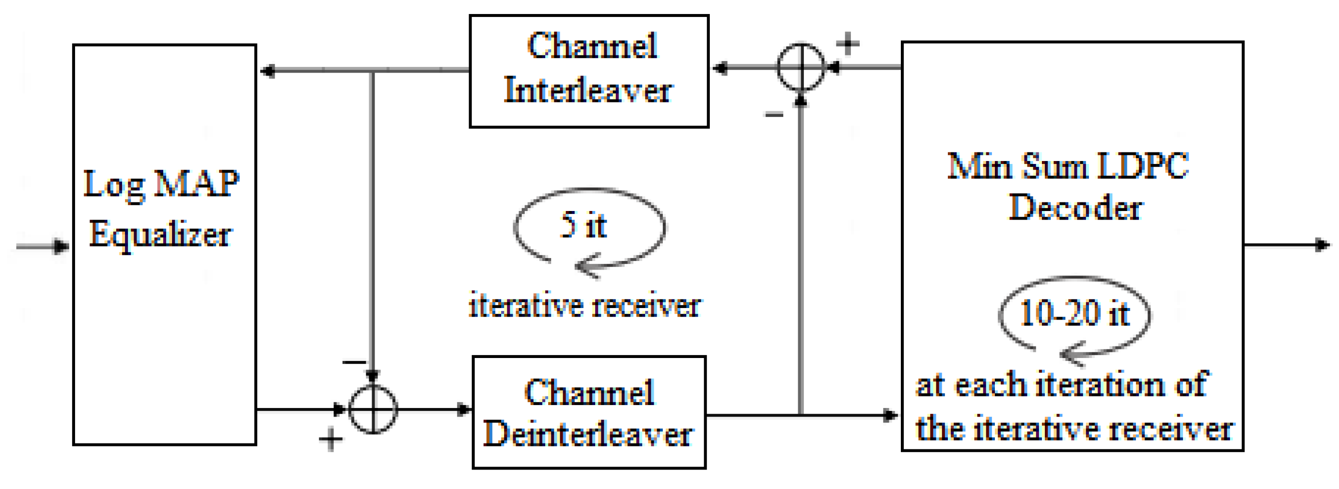
  • We proposed a system, respecting the classic turbo equalization scheme, to fix the errors introduced by ISI over an AWGN channel. However, for transmission, we utilized LDPC coding. At reception, we used a system consisting of a Log-MAP equalizer and min-sum LDPC decoding, which differs from the existing systems;
  • Then, the functional analysis of the proposed system was realized, depending on the number of iterations within the iterative process of equalization and decoding or the number of iterations within the LDPC decoder. The proposed system demonstrated the effectiveness of the equalizer in terms of BER vs. SNR;
  • Then, taking three impulse responses’ h functions as mentioned in Section 4.3 and Section 5, the performances in terms of BER vs. SNR of the proposed system were compared. These performances differed depending on the h function that was used;
  • The performances in terms of BER vs. SNR of the proposed system were also correlated in comparison with other decoding and equalization systems described in the literature [1,2,3,4,5,6,7,8,9,10,11,12,13].
The process of LDPC decoding is iterative. Each attempt to decode the input message notifies the next until a valid codeword is obtained. LDPC codes have been adopted by several standards, such as WiFi, WiMax, WiGig, DVB-S2, or 10GbaseT [15]. We should also include the enhanced mobile broadband (eMBB), ultra-reliable and low-latency communications (URLLC), and massive machine-type communications (mMTC) applications of 5G according to [15].

2. Related Work

Firstly, a summary of existing SISO equalization algorithms derived from classical equalization methods according to the maximum a posteriori (MAP) or minimum mean-square error (MMSE) criterion is presented. In this respect, we referred to [4,5,16,17,18,19,20,21,22,23,24,25,26,27].
Using soft decisions provided by the decoder at the entry of an equalizer was demonstrated to considerably reduce the BER at the reception [16,17]. From this point of view, different SISO equalization techniques were built in the literature to improve the information from the decoding levels within the iterative decoding approach.
The idea of using a priori information from the channel decoder to improve equalization was proposed in [4]. The decoder and the equalizer improve each other the estimate of the transmitted data in an iterative process similar to turbo codes. This first version of turbo equalization uses equalization based on the maximum-likelihood sequence detection (MLSD) criterion using the soft-output Viterbi algorithm (SOVA). The soft-output Viterbi equalizer used in [4] represented the first soft-in soft-out equalizer within the iterative decoding method at the reception. The soft-output Viterbi equalizer consists of trellis construction of the channel being easily decoded by applying the Viterbi algorithm. Even so, it did not succeed in decreasing the BER. Then, an adaptive turbo-equalization structure was proposed in [18]. The equalizer created on the MMSE criterion, including a priori information, was provided in [19], employing a matrix presentation of the channel. In [20], the principle for a turbo equalization technique whose coefficients are computed in the frequency domain was adopted.
Further, enhancements to the soft-output Viterbi equalizer were performed by the MAP algorithm to succeed in reducing the BER [5]. In contrast to the soft-output Viterbi equalizer, the better efficiency of the MAP equalizer comes from the higher computational complexity of the MAP equalization algorithm. Max-Log MAP, described in [21], presents a lower computational complexity in contrast to MAP equalizer but also a lower performance in terms of BER. In this sense, another method (delayed-decision-feedback sequence estimator) employed to decrease the difficulty of the MAP equalizer consisted of reducing the number of states of the trellis.
The soft-output sequential algorithm, a trellis-based equalizer presented in [7], used the sequential estimation method within the turbo equalization process. In [22], a soft-output Viterbi algorithm built on soft-output decision-feedback sequence estimation was detailed.
The minimum mean-square error linear equalizer (MMSE LE) was applied in [23] to decrease computation complexity in the case of an equalizer using a priori information. Also, the minimum mean-square error decision-feedback equalizers (MMSE DFE), including or not a priori information in the finite impulse filters, supplying hard or soft decisions, were presented in [24,25].
The iterative techniques created on the MAP or MMSE principle, including a priori information, facilitate the removal of interferences almost totally and obtain the full benefit from the diversity of the channel. These techniques can also be used for other sources of interference. Code division multiple access (CDMA) systems need to regard the interference caused by multiple users. In this respect, in [26], the iterative handling for CDMA is described. In addition, the principles of turbo equalization can be used in the issue of linear precoding or precoding multiantenna systems [27].
On the other hand, we referred to other papers [28,29,30,31] where forward-error-correction decoders (such as spatially coupled low-density parity-check codes, protograph codes, repeat-accumulate codes, spatially-coupled codes, or Bose–Chaudhuri–Hocquenghem codes) were employed in connection with the Bahl–Cock–Jelinek–Raviv (BCJR) detector or minimum mean-square error linear equalizer (MMSE LE) to mitigate the impact of ISI.
In [28], the authors integrated spatially coupled low-density parity-check codes in turbo equalization. Better said, the authors proved the performances of the spatially coupled low-density parity-check codes over the additive white Gaussian noise and inter-symbol interference channels in obtaining the target BER.
In [29], the authors depicted the configurations of the LDPC codes through one-dimensional (OD) and two-dimensional (TD) ISI channels, which are usually adopted to describe magnetic recording systems. In this sense, LDPC codes have proved their high quality for employment in magnetic recording systems. They also briefly presented the forwards in studying LDPC versions, for example, protograph codes, repeat-accumulate (RA) codes, or spatially-coupled (SC) codes, through the mentioned ISI channels. Based on this work, the authors have created some operative combined detection and decoding procedures for LDPC codes over OD-ISI channels.
A scalable FPGA-founded architecture for a Bahl–Cock–Jelinek–Raviv (BCJR) equalizer to cancel the ISI was created in [30]. The authors adopted a turbo BCJR equalizer in connection to a binary forward-error-correction decoder to interchange soft information as extrinsic Log-likelihood ratios in each turbo iteration.
The scope of [31] was to prove the performance of interference linear equalizer based on the minimum mean-square error in tandem with Bose–Chaudhuri–Hocquenghem (BCH) codes. The authors compared, in terms of BER, the performances of linear turbo equalization adopting both convolutional and BCH codes.

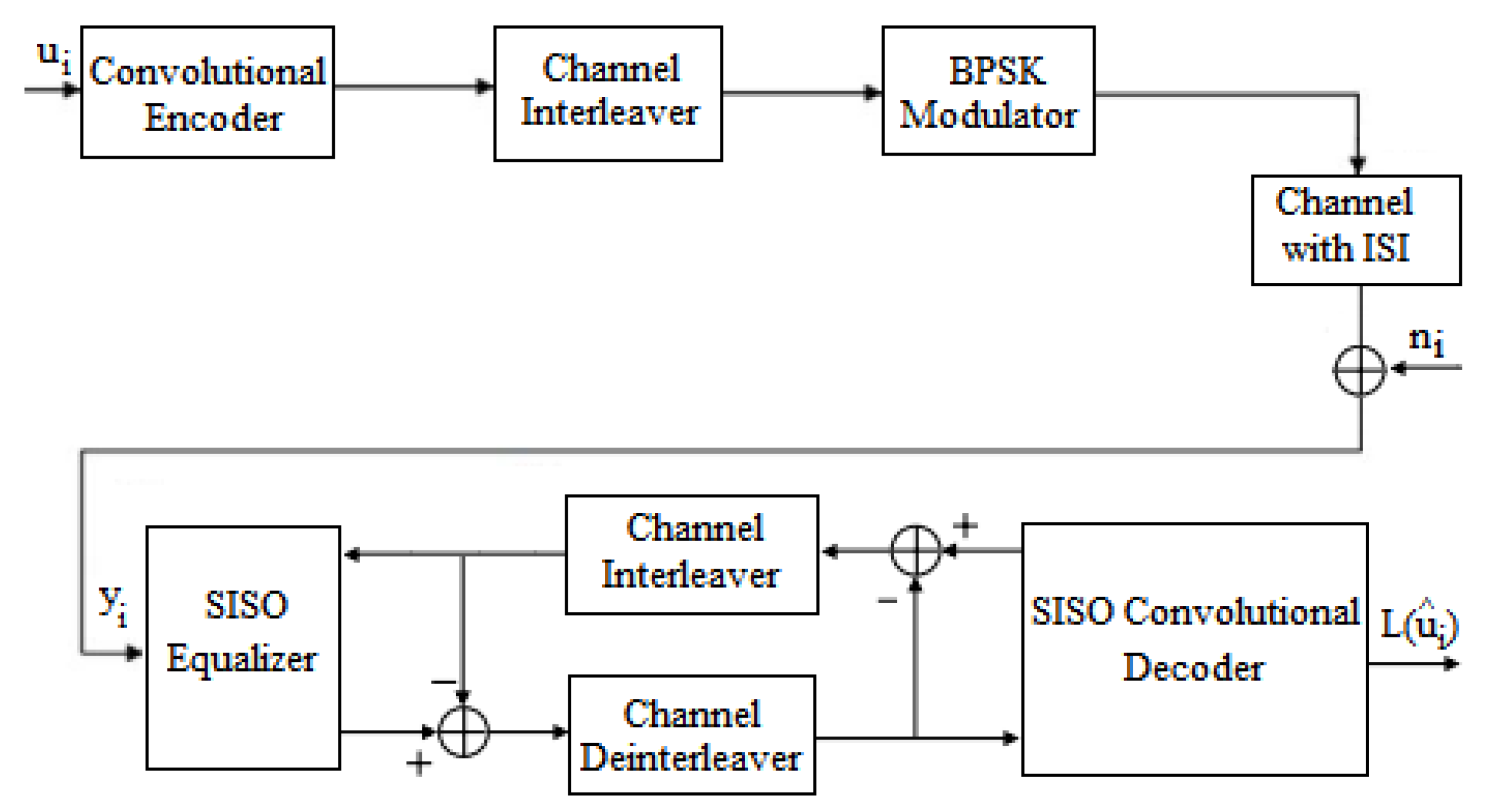
3. Turbo Equalization Concept

The concept of turbo equalization was created in the laboratories of ENST (École Nationale Supérieure des Télécommunications), Bretagne, in the early 1990s, with the support of the spectacular results obtained with turbo codes. Turbo equalization consists of a reciprocal and iterative exchange of probabilistic information (extrinsic information) between the equalizer and the decoder. The first turbo-equalization scheme was proposed in 1995 by Douillard et al. [9]. This diagram implemented a weighted input and output Viterbi equalizer according to the soft-output Viterbi algorithm (SOVA). The principle was then taken up in 1997 [32] by replacing the SOVA equalizer with an optimal SISO equalizer using the BCJR algorithm developed in [10].

3.1. The Basic Architecture of the Iterative Receiver Using the Turbo Principle

Figure 1 shows the structure of a transmitter in the presence of the convolutional encoder, the classic structure of the iterative receiver, and the model channel in the presence of intersymbol interference for BPSK modulation. Most turbo equalization architectures described in the literature use the same basic architecture, both for the SISO equalization module and for the SISO convolutional decoding module, using the BCJR algorithm [33]. In Figure 1, the input binary data sequence ui, assumed to be equiprobable, is encoded by a convolutional encoder, interleaved, mapped into BPSK symbols, and transmitted in a time-varying and frequency-selective medium. The signal from the channel output yi was corrupted by a Gaussian noise, ni.
At the reception, a turbo equalizer is used. It consists of three functions mentioned in [34]. Iterative processing is performed using these modules that exchange soft information and provide an estimate of the transmitted symbols L u ^ i for each iteration. Next, the expressions of the soft information for the MAP turbo-equalizer architecture will be presented. In this architecture, ISI cancellation is provided by a MAP detector. The principle of this architecture is that the multipath channel is similar to a convolutional code, which can be represented in the form of a trellis. Optimal detection of the symbols generated by the ISI channel can be achieved using the MAP algorithm. Figure 2 presents the block diagram of turbo equalization using the classic diagram.
In general, the turbo equalizer corresponding to the transmission scenario of Figure 1 takes the form represented in Figure 2. It consists primarily of a MAP SISO equalizer, which takes as input both the vector yi of observed data at the channel output and corrupted by Gaussian noise ni and the a priori probabilistic information provided by the MAP SISO decoder, denoted here formally L e D s ^ [5]. In the case of the first iteration, the term L e D s ^ is equal to zero, meaning that no a priori information is provided by the channel decoder. The probabilistic information is propagated in the form of a Log-likelihood ratio (LLR), whose expression is written here for ui with value in {0, 1}:
L u i y = ln P u i = + 1 y P u i = 1 y ,
where the P(ui) depicts the a priori probability of the input bits. The LLR is computed as the natural logarithm of the division between the probability of the transmitted bit ui = +1 and the one of the transmitted bit ui = −1, considering that y represents the received sequence.
The notion of LLR is twice informatory because the sign of the quantity L u i gives the firm decision on ui and its absolute value L u i evaluates the decoding credibility/likelihood of the channel [35].
The equalizer computes the a posteriori probability L E s ^ . Therefore, the extrinsic information L e E s ^ delivered by the equalizer is computed as follows:
L e E s ^ = L E s ^ L e D s ^ ,
The vector L e E s ^ is then deinterleaved to give a new sequence L e E s ^ , which constitutes the a priori information for the MAP SISO decoder. The aim of subtracting the a priori LLRs L e D s ^ from the a posteriori LLRs L E s ^ is to avoid the decoder obtaining information established on its own decisions, which were generated in the previous iteration in the turbo-equalization process.
The MAP SISO decoder delivers the a posteriori information on the coded message estimates noted L D s ^ . The extrinsic information L e D s ^ provided by the decoder is computed as follows:
L e D s ^ = L D s ^ L e E s ^ ,
The vector L e D s ^ is then interleaved to give a new sequence L e D s ^ , which is sent back to the MAP SISO equalizer, where it is used as a priori information for a new equalization step at the next iteration together with the received message yi [22]. As in the case of the equalizer, subtracting the a priori LLRs L e E s ^ from the a posteriori LLRs L D s ^ is to avoid the equalizer obtaining information established on its own decisions, which were generated in the previous iteration in the turbo-equalization process.
The iterative processing (equalization/decoding) continues until a pre-established end condition is met [36]. In the end, the output L u ^ i of the decoder delivers an estimate of the transmitted message based on decision rules:
u ^ i = 1 i f L u ^ i < 0 + 1 otherwise .

4. Methods for Achieving the Iterative Process of Equalization and Decoding Concerning the Proposed System

4.1. Log-MAP Equalizer
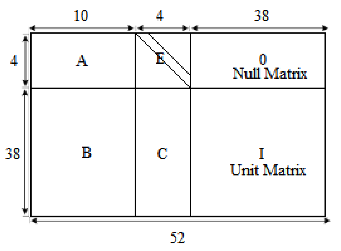
On the other hand, different optimization criteria are distinguished for realizing the SISO equalizer, leading to distinct families of turbo equalizers. The MAP turbo equalization is an optimal equalizer in the sense of maximum a posteriori likelihood [37]. The SISO equalizer is then typically implemented using the MAP algorithm, which creates LLR for each entry bit, ui. This equalizer is ideal, especially for reducing the symbol error probability. To calculate the LLR a posteriori L u i y , it was used the trellis representation associated with the transmission on the selective channel in frequency [38]. By applying the Bayes relation, the relation for LLR can be written in the sense of Equation (1).
Among the set of possible transmitted sequences, each candidate sequence draws a unique path in the trellis. It can then be evaluated the joint probability P u i = 0   o r   1 y by summing the probability P s , s , y of passing through a particular transition of the trellis connecting a state s′ at the time i − 1 to a state s at the time i, over the set of transitions between times i − 1 and i for which the bit associated with these transitions is 0 or 1. In consequence:
L u i y = ln s , s / u i = + 1 P s , s , y s , s / u i = 1 P s , s , y ,
where the ( s , s ) / u i = + 1 represents the group of transitions from state s′ to state s as a consequence of the bit ui = +1, and in the same manner, ( s , s ) / u i = 1 designates the group of transitions from state s′ to state s assignable to the bit ui = −1.
Considering a trellis example for a binary system, at each time interval, there are M = 2 transitions quitting each state and λ = 4 transitions caused by the bit ui = +1, which belong to the set of ( s , s ) / u i = + 1 . In the same way, there will be λ = 4 transitions assignable to the bit ui = −1, belonging to the group of ( s , s ) / u i = 1 . Considering a modulation with M states and a discrete channel with L coefficients, the total number of branches per section of the trellis amounts to MxML-1 = ML [1].
By adopting an approach similar to that presented in the original article by Bahl et al. [10], it can be shown that the joint probability P s , s , y associated with each transition considered breaks down into a product of three terms:
P s , s , y = α i 1 s γ i s , s β i s ,
The probabilities α and β are computable recursively for each state and each moment in the trellis, by applying the following recursive formulas:
α i s = s , s α i 1 s γ i s , s ,   Initial   values :   α 0 s = 1 s = 0 0 s 0
β i 1 s = s , s γ i s , s β i s ,   Initial   values :   β N s = 1 M L 1 , s
These two probabilities are named “forward probability” and “backward probability”, respectively. The summations relate to the set of pairs of states with indices s , s for which there is a valid transition between two consecutive moments in the trellis. The initial condition or the starting state (index 0 by convention) is perfectly known. To assign equal weight to each state in back recursion is a common practice, as the state of arrival is usually unknown.
To complete the description of the algorithm, the term γ i s , s in Equation (6) remains to be developed further. This term is assimilated to the transition probability. It can be split into a product of two factors:
γ i s , s = P u i P y i s , s ,
where the term P u i represents the a priori probability of the input bit, ui, and P y i s , s is the probability that the signal yi has been received since the passing from s′ to s happened at moment i. Therefore, considering an AWGN channel for receiving the estimated signal y ^ i , the term P y i s , s can be written as follows:
P y i s , s = 1 2 π σ 2 exp 1 2 σ 2 y i y ^ i 2 ,
Converting α i s and β i 1 s into the logarithmic domain [39] the recursive formulas for forward and backward recursion are as follows:
A i s = ln α i s = ln s , s α i 1 s γ i s , s = ln s , s exp A i 1 s + Γ i s , s ,
B i 1 s = ln β i 1 s = ln s , s γ i s , s β i s = ln s , s exp Γ i s , s + B i s ,
where Γi(s′,s) represents the logarithmic domain conversion of γi(s′,s). Therefore, applying the same method for γ i s , s , A i s and B i 1 s can be computed as follows:
Γ i s , s = ln γ i s , s = ln P u i P y i s , s ,
Using Equation (10), Γ i s , s becomes:
Γ i s , s = ln 1 2 π σ 2 1 2 σ 2 y i y ^ i 2 + ln P u i ,
In Equation (14) presuming that the bits transmitted own the same probability, P u i is an unchanging factor and can be omitted. Also, the term ln 1 2 π σ 2 could be omitted. Consequently, Equation (14) can be rewritten as follows:
Γ i s , s = 1 2 σ 2 y i y ^ i 2 ,
In summary, after computing the branch metric and then performing forward and backward recursions [40], the a posteriori LLR is finally given:
L u i y = ln s , s / u i = + 1 α i 1 s γ i s , s β i s s , s / u i = 1 α i 1 s γ i s , s β i s = ln s , s / u i = + 1 exp A i 1 s + Γ i s , s + B i s s , s / u i = 1 exp A i 1 s + Γ i s , s + B i s
Therefore, using this Equation (16), the a posteriori LLR values for each input bit can be calculated. In consequence, the decision rule says that when L u i y 0 (the logarithm of the likelihood ratio) then ui = +1, and vice versa when L u i y < 0 then ui = −1.

4.2. LDPC Codes

Low-density parity-check codes were proposed/designated by Gallager in the early 1960s and rediscovered by MacKay in 1995, after the development of turbo codes at ENST Bretagne in the early 1990s. The LDPC code is a binary linear block code of length N defined by a sparse parity-check matrix H of dimension M × N . The c codewords consist of a sequence of N bits satisfying a set of M parity-check equations [41]. This results in the following equation called the parity-check equation:
H × c T = 0 ,
The message bits m, parity (redundant) bits p, and codeword bits c satisfy the equation:
c T = m T p T ,
As previously stated, the second base matrix (BG2) defined in 3rd Generation Partnership Project (3GPP) Technical Specifications [42] is built in a structured manner, with a structure of double diagonal that can be fully used to process LDPC coding. Figure 3 depicts the block structure for the BG2 matrix according to the 5G standard as it mentioned in [42].
The main point of LDPC coding is the calculation of parity bits. In this paper, the parity bits p were calculated based on the double diagonal structure according to 5G standard.
Taking into consideration the block structure of BG2 and Equation (18), the parity-check Equation (17) for encoding can be rewritten as follows [43]:
H × c T = A E 0 B C I m T p 1 T p 2 T ,
The information bits m with a length of 10Zc, the first set of parity bits p1 with a length of 4Zc, and the second set of parity bits p2 with a length of 38Zc correspond to A B T , E C T , and 0 I T of the BG2 matrix. Zc represents the expansion factor.
From Equation (19) it follows that the parity bits are computed as follows:
p 1 T = A m T B 1 ,
p 2 T = E m T + C p 1 T ,
Concerning the LDPC decoding, the min-sum algorithm was used in this paper. This algorithm can be seen as a message propagation algorithm on the associated factorial graph. The messages passing through the branches of the Tanner graph are probabilities. The principle of belief propagation is the application of Bayes’ rule locally (on each bit) and iteratively to estimate the a posteriori probabilities of each bit [44].
The min-sum algorithm is a soft-decision algorithm that consists of message passing between variable and check nodes [45]; the iterative steps of the min-sum algorithm, for each iteration, are according to [46].
The min-sum decoder stops immediately whenever a valid codeword has been found, checking whether the parity-check equations are satisfied c ^ H T = 0 or the maximum number of iterations has been reached.

4.3. The Proposed System Model

In this paper, a transmission scheme on AWGN channels with ISI was proposed according to Figure 4.
The proposed transmission scheme described in Figure 4 follows the basic architecture of the iterative receiver using the turbo equalizer presented in Figure 1 in Section 3.1. The differences consist of the LDPC encoding of the input binary data sequence ui used for transmission, and the Log-MAP equalizer and the min-sum LDPC decoder were used for reception in the iterative and decoding equalization process. In other words, the bit sequence (data) ui is LDPC encoded, and then it is punctured to obtain a rate of ½, interlaced, and BPSK modulated. Next, the signal is transmitted through the AWGN channel with ISI, and the reception follows the classic turbo equalization scheme, but in this case, using a Log-MAP equalizer and an LDPC decoder.
In the research process related to LDPC coding, the BG2 base matrix, according to the standard [41] with the expansion factor Zc = 20, was used. A total of 10,000 sequences of 200 bits of information each (K = 200) were transmitted. After the coding process, the length of the code words is N = 440 bits. To obtain a rate of ½, the first 2Zc bits were punctured according to the standard. The N-2Zc length message is then interleaved, modulated, and transmitted on an AWGN channel with ISI.
In this paper, three impulse responses’ h functions used in the literature were taken, each having three different weights. They are as follows: h1 = [0.18 0.85 0.32] [13], h2 = [0.302 0.725 0.456] [47], and h3 = [0.407 0.815 0.407] [48].
Following the basic turbo-equalizer concept, the received signal yi enters the Log-MAP equalizer, as presented in Figure 4. The equalizer knows the impulse response h, making a first estimate of the transmitted sequence yi.
In the iterative process of equalization and decoding, the equalizer works with the interlaced sequence and the decoder with the deinterlaced sequence. The data from the Log-MAP equalizer are deinterlaced and sent to the decoder, which makes a first estimate of the transmitted information bits. During the decoding process, the decoder also makes a first estimate of the first 2Zc bits that were punctured after coding. The min-sum LDPC decoder works iteratively, as was mentioned in Section 4.2.
Considering that the equalizer works with N-2Zc bits (in our case, with 400 bits), information about only these bits will be transmitted from the decoder to the Log-MAP equalizer. That is, from 2Zc + 1 to N. This information is interlaced not before subtracting the information from the input of the decoder from the previous iteration so that it does not receive its information as a priori information.
Based on the a priori information from the decoder and the information at the exit of the channel, the equalizer improves the estimate of the transmitted sequence with each iteration. This information from the Log-MAP equalizer is deinterlaced and sent to the decoder, not before subtracting the a priori information from the input of the equalizer from the previous iteration; thus, it does not receive its information as a priori information. At the output of the decoder, the first K bits estimated values from the N values represent estimates of the transmitted information bits.
In this work, all LLRs transmitted from the decoder to the equalizer and vice versa are weighted with their maximum absolute value.
LDPC decoders offer a low-complexity implementation compared to other forward error-correcting codes, according to [15,49,50].
In contrast to the MAP algorithm used by the SISO decoder from the classic turbo equalization scheme, which requires a large memory as well as many multiplication and exponentiation operations [51], the min-sum algorithm used by the LDPC decoder of our proposed system simplifies the computational complexity by using simple arithmetic operations according to [50].

5. Simulation Results and Discussion

The simulation results were attained using Matlab and are presented in the following. As a rule, all graphics were plotted for an SNR that varies between 0–10 dB, but where the graphics display values for SNR lower than 10 dB, it means that in those cases, no more errors were found over the respective values.
In the iterative process of equalization and decoding, there are iterations carried out in both the ensemble process (equalization–decoding) and within the LDPC decoder. It should be mentioned that in this work, five iterations were performed within the iterative process of equalization and decoding. During one iteration of the iterative receiver, the LDPC decoder performs either 10 or 20 iterations, depending on the specific situation being analyzed. This process is illustrated in Figure 5.
We arranged all the simulation scenarios in Table 1 to make it easier for the reader to follow.
To notice the role of the Log-MAP equalizer, two scenarios were considered. In the first scenario, iteration 0 (it0) and iteration 1 (it1) were considered in the iterative process of equalization and decoding. In iteration 0 (it0), the Log-MAP equalizer does not receive any a priori information from the min-sum LDPC decoder, thus realizing the a posteriori information only based on the data observed from the channel output [5]. At each of the two iterations of the iterative receiver, the LDPC decoder makes ten iterations. In the second scenario, there is only one iteration (test) in the iterative process of equalization and decoding. The number of iterations in the decoder is 20, which is the sum of the cumulative iterations of the first scenario (10 by 10).
In it0, the a posteriori information from the equalizer is deinterlaced and then provided to the decoder. In the case of iteration 0 (it0) the Log-MAP equalizer does not receive any a priori information from the decoder. On the other hand, iteration 1 (it1) involves the whole iterative process of equalization and decoding. The a posteriori information from the equalizer is deinterlaced and then provided to the decoder. The Log-MAP equalizer receives the a priori information from the decoder after it has been interlaced. So, the second scenario (test) is like it0, only that the decoder makes more iterations.
The analysis was conducted by considering h1 = [0.18 0.85 0.32]. In this sense, Figure 6a demonstrates that BER vs. SNR improves when the LDPC decoder performs ten iterations at each of the two iterations of the iterative receiver.
The role of the Log-MAP equalizer is better seen in Figure 6b. In this case, two scenarios were considered. The first scenario makes two iterations (it0 and it1) within the iterative process of equalization and decoding, as the LDPC decoder makes 20 iterations at each of the two iterations of the iterative receiver. The second one makes a single iteration (test) within the iterative receiver, as the number of iterations in the decoder (40) is the sum of the cumulative iterations of the first scenario (20 by 20). In this case, it was considered the same h1 = [0.18 0.85 0.32].
In Figure 6b it can be seen that at an SNR of 5 dB, the BER related to the test is located at 10−4 while the BER related to it1 decreases, being situated between 10−4 and 10−5.
Next, taking the three impulse responses h1 = [0.18 0.85 0.32], h2 = [0.302 0.725 0.456], and h3 = [0.407 0.815 0.407] as mentioned in Section 4.3, the performances in terms of BER vs. SNR of the proposed system were compared, these differing on the h function used, as it could be observed in Figure 7a–c.
At each iteration in the iterative process of equalization and decoding, 10,000 sequences were generated, and 10 iterations took place in the LDPC decoder.
At the same time, it is observed that these performances, using the same type of channel with ISI, also differed depending on h, the best performance being obtained in the case of h1. For instance, when the signal-to-noise ratio (SNR) is at 5 dB, the bit error rate (BER) ranges between 10−4 and 10−5, as shown in Figure 7a.
On the other hand, for a channel with h2 at the SNR of 5 dB, the BER is approximately 10−1, Figure 7b. Similarly, in the case of an ISI channel with h3, the BER is positioned between 10−1 and 10−2 when the SNR is at 5 dB, Figure 7c.
The previous scenario was reconsidered in the case that the LDPC decoder achieves 20 iterations. This is reflected in Figure 8a–c. If the decoder makes 20 iterations inside itself (within the decoding process), the performance increases, the most visible being for the channel characterized by h1. After the SNR of 4 dB, the proposed system no longer finds any errors.
Table 2 summarizes the BER vs. SNR performances of the proposed system while considering h1, h2, and h3 in two scenarios: when the LDPC decoder executes 10 or 20 iterations at each iteration of the iterative process of equalization and decoding.
To analyze the performance of the proposed system, it was compared with two other equalization and decoding systems, for the same conditions of the transmission channel. The first system consists of turbo equalization that follows the classic scheme, according to the theory mentioned in Section 3. The recursive systematic convolutional (RSC) encoder was used in this study using the octal generating polynomials G0 = 7 and G1 = 5, at a rate R = 1/2 and constraint K = 3.
The second system consists of the equalization performed separately before the decoding process using MMSE equalizer and LDPC decoder at a rate of ½, similar to [13].
For example, for a channel with h1, at the SNR of 5 dB, in the case of our proposed system, as was specified earlier, the BER is situated between 10−4 and 10−5 if ten iterations are made in the LDPC decoder and for 20 iterations within the LDPC decoder at the SNR of 5 dB for iterations 1–5 no more errors were found.
In the case of turbo equalization at the same SNR of 5 dB, for a channel with h1, the BER is 10−3, as can be observed in Figure 9a. But, for a channel with h2 or h3, the BER is situated between 10−2 and 10−3, as can be noticed in Figure 9b,c.
In Figure 10a for h1 in the case of the separate equalization performed before the decoding process, using MMSE and LDPC decoder, at the SNR of 5 dB, the BER is located between 10−5 and 10−6 (if the decoder makes 40 iterations). Constant performance was shown over 40 iterations with a BER between 10−5 and 10−6, as demonstrated in Figure 10b.
Repeating the previous scenario, Figure 11a and Figure 12a show that the BER deteriorates considerably for h2 and h3 at the SNR of 5 dB, being within 100 and 10−1. The graphics in Figure 11b and Figure 12b demonstrate a relatively constant level of BER over 40 iterations.
Table 3 summarizes the BER vs. SNR performances of turbo equalization and separate MMSE equalization with LDPC decoding.
Table 4 summarizes the BER vs. SNR performances of the proposed system, turbo equalization, and separate MMSE equalization with LDPC decoding.
It can be noticed that the proposed system’s results for h1 are comparable to separate equalization with MMSE and better than turbo equalization, as can be deduced from Table 1 and Table 2. On the other hand, MMSE with LDPC yields poor results, ranging from 100 to 10−1 for h2 and h3.
The system model proposed in this study (LDPC decoder performs 20 iterations) outperforms turbo equalization for an SNR higher than 4 dB for the channel with h1.
For a channel with h2 and h3, for an SNR higher than 7 dB, the system proposed by us (when LDPC decoder performs 20 iterations) is more efficient than turbo equalization and MMSE with LDPC decoding.
If we deviate from the standard and do not puncture the first 2Zc bits and transmit 440 bits in the case of the proposed system, for the three h, the results are presented as follows in Figure 13a–c. The coding rate is approximately ½, not being adjusted by puncturing. We considered the situation in which the LDPC decoder performs 20 iterations during one iteration of the iterative process of equalization and decoding.
Table 5 highlights the performances of the system proposed in this study (the LDPC decoder makes 20 iterations at one iteration of the iterative equalization and decoding process) with puncturing and without puncturing the first 2Zc bits, for the SNR of 5 dB.
The results are better than in the case of puncturing the first 2Zc bits according to standard.
The equalizers and decoders do not always match equally well to each other to obtain satisfactory results. But in this paper, it was found a combination between the Log-MAP equalizer and the min-sum LDPC decoder that offers the presented performances. In addition, it was made a comparison of the proposed scheme with other established models in the specialized literature, such as turbo equalization or MMSE equalization combined with LDPC decoding.
The impulse responses were not chosen randomly; they can be found in the specialized literature and are referenced in the text.

6. Conclusions

In this study, we proposed a system that respects the classic turbo-equalization scheme. We used an LDPC coder for transmission and a Log-MAP equalizer for reception, connected with a min-sum LDPC decoder.
We performed the performance analysis of the proposed system, BER vs. SNR, considering three different h functions. It has been experimentally demonstrated that increasing the number of iterations performed by the LDPC decoder from 10 to 20 in the iterative process of equalization and decoding leads to improved results (as can be observed in Table 2, Section 5).
Then, the proposed system was compared with turbo equalization and separate equalization with MMSE and LDPC decoding in terms of BER vs. SNR, considering the three different h functions.
Based on the analyzed results, the equalization performance depends on both the impulse response of the channel and the chosen decoding and equalization method; some decoding and equalization systems offered better results, depending on h function (as can be observed in Table 4, Section 5).
Not puncturing the first 2Zc bits, the proposed system achieved better BER vs. SNR performance (as can be observed in Table 5, Section 5).
In conclusion, Table 6 compares the performances in terms of BER vs. SNR of the proposed approach to others published in the literature, demonstrating its performances.
The comparison with other papers in the literature is not the most eloquent because the simulation parameters and the methods differ from those proposed in this paper.
In the future, channel estimation, using the least-square (LS) channel estimator, can be integrated into the iterative process of equalization and decoding, and thus BER performance can be improved during iterations.
We should also consider performing an EXIT chart analysis as a future perspective.
In this paper, we have limited ourselves to LDPC codes and turbo codes, as they are currently considered to be among the most relevant [52,53].

Author Contributions

Conceptualization, A.-M.C., F.L.M. and C.G.; methodology, A.-M.C. and F.L.M.; software, A.-M.C. and F.L.M.; validation, A.-M.C., F.L.M., A.-M.G. and C.G.; formal analysis, A.-M.G. and C.G.; investigation, A.-M.C.; resources, F.L.M.; data curation, A.-M.C. and A.-M.G.; writing—original draft preparation, A.-M.C. and F.L.M.; writing—review and editing, A.-M.C., A.-M.G. and C.G.; visualization, A.-M.C. and A.-M.G.; and supervision, A.-M.G. and C.G. All authors have read and agreed to the published version of the manuscript.

Funding

The research was funded by Romanian Ministry of Research, Innovation and Digitisation through Programme 1—Development of the National Research and Development System, Subprogramme 1.2—Institutional Performance—Projects for funding the excellence in RDI, Contract No. 29 PFE/30.12.2021 with University of Oradea, Oradea, Romania. The APC was funded by the University of Oradea.

Institutional Review Board Statement

Not applicable.

Data Availability Statement

The data used in this study are available from the corresponding author upon reasonable request.

Conflicts of Interest

The authors declare no conflict of interest.

References

  1. Berrou, C. Codes and Turbo Codes, 1st ed.; Springer: Paris, France, 2010; pp. 359–412. [Google Scholar]
  2. Wang, L.; Qiao, P.; Liang, J.; Chen, T.; Wang, X.; Yang, G. Accurate Channel Estimation and Adaptive Underwater Acoustic Communications Based on Gaussian Likelihood and Constellation Aggregation. Sensors 2022, 22, 2142. [Google Scholar] [CrossRef] [PubMed]
  3. Yeap, B.L.; Hanzo, L. Reduced complexity I/Q turbo detection for space-time trellis-coded systems. IEEE Trans. Veh. Technol. 2004, 53, 1278–1286. [Google Scholar] [CrossRef]
  4. Douillard, C.; Picart, A.; Jézéquel, M.; Didier, P.; Berrou, C.; Glavieux, A. Iterative correction of intersymbol interference: Turbo-equalization. Eur. Trans. Commun. 1995, 6, 507–511. [Google Scholar] [CrossRef]
  5. Hanzo, L.; Liew, T.H.; Yeap, B.L.; Tee, R.Y.S.; Ng, S.X. Turbo Coding, Turbo Equalisation and Space-Time Coding: EXIT-Chart-Aided Near-Capacity Designs for Wireless Channels, 2nd ed.; Wiley-IEEE Press: Hoboken, NJ, USA, 2011; pp. 253–384. [Google Scholar]
  6. Sahin, S.; Cipriano, A.M.; Poulliat, C.; Boucheret, M.-L. Iterative Decision Feedback Equalization Using Online Prediction. IEEE Access 2020, 8, 23638–23649. [Google Scholar] [CrossRef]
  7. Pan, Z.; Xie, C.; Wang, H.; Wei, Y.; Guo, D. Blind Turbo Equalization of Short CPM Bursts for UAV-Aided Internet of Things. Sensors 2022, 22, 6508. [Google Scholar] [CrossRef]
  8. Huang, X.; Cho, J.; Hashemizadeh, K.; Chen, R.-R. Extrinsic Neural Network Equalizer for Channels with High Inter-Symbol-Interference. In Proceedings of the ICC 2021-IEEE International Conference on Communications, Xiamen, China, 28–30 July 2021; IEEE: New York, NY, USA, 2021; pp. 1–6. [Google Scholar]
  9. Yuan, Z.D.; Liu, F.; Guo, Q.H.; Wang, Z. Message passing based detection for orthogonal time frequency space modulation. ZTE Commun. 2021, 19, 34–44. [Google Scholar]
  10. Bahl, L.R.; Cocke, J.; Jelinek, F.; Raviv, J. Optimal decoding of linear codes for minimizing symbol error rate. IEEE Trans. Inf. Theory 1974, 20, 284–287. [Google Scholar] [CrossRef]
  11. Barry, J. Equalization. In Academic Press Library in Mobile and Wireless Communications Transmission Techniques for Digital Communications, 1st ed.; Wilson, K., Biglieri, E., Wilson, S.G., Eds.; Academic Press: Cambridge, MA, USA, 2016; pp. 283–331. [Google Scholar]
  12. Liu, H.; Zhang, L. Faster than Nyquist Signaling with Spatial Coupling; Tryckeriet i E-huset, Lund: Lund, Sweden, 2022. [Google Scholar]
  13. Cuc, A.-M.; Morgoș, F.L.; Grava, C. Performance Analysis of Turbo Codes, LDPC Codes, and Polar Codes over an AWGN Channel in the Presence of Inter Symbol Interference. Sensors 2023, 23, 1942. [Google Scholar] [CrossRef]
  14. Cuc, A.-M.; Morgoș, F.L.; Grava, C. Performances Analysis of Turbo Codes, LDPC Codes and Polar Codes using AWGN channel with and without Inter Symbol Interference. In Proceedings of the 2022 International Symposium on Electronics and Telecommunications (ISETC), Timisoara, Romania, 10–11 November 2022; IEEE: New York, NY, USA, 2022; pp. 1–4. [Google Scholar]
  15. Shao, S.; Hailes, P.; Wang, T.Y.; Wu, J.Y.; Maunder, R.G.; Al-Hashimi, B.M.; Hanzo, L. Survey of Turbo, LDPC, and Polar Decoder ASIC Implementations. IEEE Commun. Surv. Tutor. 2019, 21, 2309–2333. [Google Scholar] [CrossRef]
  16. Chen, W.; Zhao, T.; Han, C. Soft Decision Decoding with Cyclic Information Set and the Decoder Architecture for Cyclic Codes. Electronics 2023, 12, 2693. [Google Scholar] [CrossRef]
  17. Zhao, Y.; Xiao, Y.; Yang, P.; Dong, B.; Hanzo, L. Joint Iterative Channel Estimation and Frequency-Domain Turbo Equalization for Single-Carrier Spatial Modulation. IEEE Trans. Commun. 2019, 67, 6327–6342. [Google Scholar] [CrossRef]
  18. Glavieux, A.; Laot, C.; Labat, J. Turbo-équalization over a frequency selective channel. In Proceedings of the International Symposium on Turbo Codes and Related Topics, Brest, France, 3–5 September 1997; Volume 962102, pp. 96–101. [Google Scholar]
  19. Tüchler, M.; Singer, A.C.; Koetter, R. Minimum mean squared error equalization using a priori information. IEEE Trans. Signal Process. 2002, 50, 673–683. [Google Scholar] [CrossRef]
  20. Laot, C.; Bidan, R.L.; Leroux, D. Low-Complexity MMSE Turbo Equalization: A Possible Solution for EDGE. IEEE Trans. Wirel. Commun. 2005, 4, 965–974. [Google Scholar] [CrossRef]
  21. Tüchler, M.; Singer, A.C. Turbo equalization: An overview. IEEE Trans. Inf. Theory 2011, 57, 920–952. [Google Scholar] [CrossRef]
  22. Dong, P.; Xiang, X.; Liang, Y.; Wang, P. A Block-Based Concatenated LDPC-RS Code for UAV-to-Ground SC-FDE Communication Systems. Electronics 2023, 12, 3143. [Google Scholar] [CrossRef]
  23. Li, H.; Yu, Q. Doubly-Iterative Sparsified MMSE Turbo Equalization for OTFS Modulation. IEEE Trans. Commun. 2023, 71, 1336–1351. [Google Scholar] [CrossRef]
  24. Yu, L.; Zhao, J.; Xu, W.; Liu, H. Design of Sparse FIR Decision Feedback Equalizers in MIMO Systems Using Hybrid l1/l2 Norm Minimization and the OMP Algorithm. Sensors 2018, 18, 1860. [Google Scholar] [CrossRef]
  25. Şahin, S.; Cipriano, A.M.; Poulliat, C.; Boucheret, M.-L. Iterative Equalization With Decision Feedback Based on Expectation Propagation. IEEE Trans. Commun. 2018, 66, 4473–4487. [Google Scholar]
  26. Plascencia, E.; Guan, H.; Chassagne, L.; Căilean, A.-M.; Barrois, O.; Shagdar, O. Addressing Multi-User Interference in Vehicular Visible Light Communications: A Brief Survey and an Evaluation of Optical CDMA MAC Utilization in a Multi-Lane Scenario. Sensors 2023, 23, 3831. [Google Scholar] [CrossRef]
  27. Altalbe, A.; Tahir, M. Performance of Iterative Coded CDMA Receivers with APP Feedback: A Use of a Weighted Delay Filter. Appl. Sci. 2023, 13, 9175. [Google Scholar] [CrossRef]
  28. Khittiwitchayakul, S.; Phakphisut, W.; Supnithi, P. Integer programming-based non-uniform window decoding schedules for spatially coupled low-density parity-check codes. IET Commun. 2022, 16, 2019–2035. [Google Scholar] [CrossRef]
  29. Fang, Y.; Han, G.; Cai, G.; Lau, F.C.M.; Chen, P.; Guan, Y.L. Design Guidelines of Low-Density Parity-Check Codes for Magnetic Recording Systems. IEEE Commun. Surv. Tutor. 2018, 20, 1574–1606. [Google Scholar] [CrossRef]
  30. Matar, M.O.; Jana, M.; Mitra, J.; Lampe, L.; Lis, M. A Turbo Maximum-a-Posteriori Equalizer for Faster-than-Nyquist Applications. In Proceedings of the 2020 IEEE 28th Annual International Symposium on Field-Programmable Custom Computing Machines (FCCM), Fayetteville, AR, USA, 3–6 May 2020; pp. 167–171. [Google Scholar]
  31. Mishra, K. Study & Simulation of MMSE IC-LE Turbo Equalization Scheme Using Block (BCH) Turbo Codes. 2006. Available online: https://www.semanticscholar.org/paper/STUDY-%26-SIMULATION-OF-MMSE-IC-LE-TURBO-EQUALIZATION-Mishra/6754173f1a471f536088fe03f1fc2d5b3184198b (accessed on 16 January 2023).
  32. Bauch, G.; Khorram, H.; Hagenauer, J. Iterative equalization and decoding in mobile communications systems. TG FACHBERICHT 1997, 145, 307–312. [Google Scholar]
  33. Naranjo, M.Á.P.; Gil Jiménez, V.P. CCSDS 131.2-B-1 Serial Concatenated Convolutional Turbo Decoder Architecture for Efficient FPGA Implementation. IEEE Access 2023, 11, 7698–7713. [Google Scholar] [CrossRef]
  34. Ye, Z. Traitement Statistique de L’information et du Signal Pour L’internet des Objets Sous-Marins; Institut Polytechnique: Paris, France, 2021. [Google Scholar]
  35. Cao, A.; Zhang, L.; Qiao, J.; He, Y. An LLR-Based Segmented Flipped SCL Decoding Algorithm for Polar Codes. In Proceedings of the 2019 IEEE/CIC International Conference on Communications in China (ICCC), Changchun, China, 11–13 August 2019; pp. 724–729. [Google Scholar]
  36. Dörner, S.; Clausius, J.; Cammerer, S.; Brink, S.T. Learning Joint Detection, Equalization and Decoding for Short-Packet Communications. IEEE Trans. Commun. 2023, 71, 837–850. [Google Scholar] [CrossRef]
  37. Charles-Darby, K.; Carrasco-Alvarez, R.; Parra-Michel, R. Complexity Reduction of MLSE and MAP Equalizers Using Modified Prolate Basis Expansion. Electronics 2019, 8, 1333. [Google Scholar] [CrossRef]
  38. Li, X.; Wu, J.; Heng, W.; Huang, Y. Iterative Receiver Design for Probabilistic Constellation Shaping in ISI Channel. IEEE Access 2020, 8, 210478–210489. [Google Scholar] [CrossRef]
  39. Le, V.H.S. Conception des Turbocodes à Très Haut-Débit; L’école Nationale Superieure Mines-Telecom Atlantique: Pays de la Loire, France, 2021. [Google Scholar]
  40. Islam, N.S. LDPC Codes Incorporating Source, Noise, and Channel Memory; Jacobs University: Bremen, Germany, 2022. [Google Scholar]
  41. Nguyen, T.T.B.; Nguyen Tan, T.; Lee, H. Efficient QC-LDPC Encoder for 5G New Radio. Electronics 2019, 8, 668. [Google Scholar] [CrossRef]
  42. Multiplexing and Channel Coding. Document TS 38.212 V17.3.0, 3GPP. 2022. Available online: https://www.etsi.org/deliver/etsi_ts/138200_138299/138212/17.03.00_60/ts_138212v170300p.pdf (accessed on 16 January 2023).
  43. Petrović, V.L.; El Mezeni, D.M.; Radošević, A. Flexible 5G New Radio LDPC Encoder Optimized for High Hardware Usage Efficiency. Electronics 2021, 10, 1106. [Google Scholar] [CrossRef]
  44. Yun, I.; Lee, H.; Kim, J.T. An Alternative Approach Obtaining a Normalization Factor in Normalized Min-Sum Algorithm for Low-Density Parity-Check Code. Wirel. Commun. Mob. Comput. 2018, 2018, 1398191:1–1398191:7. [Google Scholar] [CrossRef]
  45. Shrinidhi, J.; Sri Krishna, P.; Yamuna, B.; Pargunarajan, K. Modified Min Sum Decoding Algorithm for Low Density Parity Check Codes. Procedia Comput. Sci. 2020, 171, 2128–2316. [Google Scholar] [CrossRef]
  46. Chen, R.; Chen, L. Dual Threshold Self-Corrected Minimum Sum Algorithm for 5G LDPC Decoders. Information 2020, 11, 355. [Google Scholar] [CrossRef]
  47. Morgoș, F.L. Contribuţii Privind Îmbunătăţirea Tehnicilor de Egalizare ale Canalelor Radio; Politehnica: Timisoara, Romania, 2014. [Google Scholar]
  48. Hanzo, L.; Liew, T.H.; Yeap, B.L.; Tee, R.Y.S.; Ng, S.X. Turbo Equalisation. In Turbo Coding, Turbo Equalisation and Space–Time Coding for Transmission over Fading Channels, 1st ed.; Wiley-IEEE Press: Hoboken, NJ, USA, 2002; pp. 553–697. [Google Scholar]
  49. Gunnam, K.K.; Choi, G.S. Low Density Parity Check Decoder for Regular LDPC Codes. U.S. Patent US 8,656,250 B2, 18 February 2014. Available online: https://hdl.handle.net/1969.1/177060 (accessed on 13 June 2023).
  50. Kumar, D.D.; Selvakumari, R.S. Performance analysis of Min-Sum based LDPC decoder architecture for 5G new radio standards. Mater. Today Proc. 2022, 62, 4965–4972. [Google Scholar] [CrossRef]
  51. Chen, X.; Zhao, M.; Chen, J.; Wang, J. High Performance Channel Decoders on CELL Broadband Engine for WiMAX System. Majlesi J. Electr. Eng. 2011, 5, 21–31. [Google Scholar] [CrossRef]
  52. Jiang, Y.; Kim, H.; Asnani, H.; Kannan, S.; Oh, S.; Viswanath, P. Turbo Autoencoder: Deep learning based channel codes for point-to-point communication channels. Neural Inf. Process. Syst. 2019, 248, 2758–2768. [Google Scholar]
  53. D3.3—Report on Link-Level Simulation Performance Final Results. Available online: https://ec.europa.eu/research/participants/documents/downloadPublic?documentIds=080166e5d3175eca&appId=PPGMS (accessed on 15 May 2023).
Figure 1. Convolutional coded system, applying the turbo equalization, achieving equalization and channel decoding iteratively.
Applsci 13 12294 g001
Figure 2. Turbo equalizer using MAP criterion.
Applsci 13 12294 g002
Figure 3. Block structure of BG2 according to 5G standard.
Applsci 13 12294 g003
Figure 4. LDPC coded system achieving equalization and channel decoding iteratively.
Applsci 13 12294 g004
Figure 5. The iterative receiver proposed for ISI channels.
Applsci 13 12294 g005
Figure 6. The contribution of the Log-MAP equalizer to the BER performance vs. SNR, the considered h1 = [0.18 0.85 0.32]: (a) First scenario—the iterative receiver makes it0 and it1, while the LDPC decoder makes ten iterations at each. Second scenario—the iterative receiver makes only a single iteration, while the LDPC decoder makes 20 iterations and (b) First scenario—the iterative receiver makes it0 and it1, while the LDPC decoder makes twenty iterations at each. Second scenario—the iterative receiver makes only a single iteration, while the LDPC decoder makes 40 iterations.
Applsci 13 12294 g006
Figure 7. BER vs. SNR, LDPC decoder–10 iterations: (a) h1 = [0.18 0.85 0.32]; (b) h2 = [0.302 0.725 0.456]; and (c) h3 = [0.407 0.815 0.407].
Applsci 13 12294 g007
Figure 8. BER vs. SNR, LDPC decoder–20 iterations: (a) h1 = [0.18 0.85 0.32]; (b) h2 = [0.302 0.725 0.456]; (c) h3 = [0.407 0.815 0.407].
Applsci 13 12294 g008
Figure 9. BER vs. SNR, using turbo equalization: (a) h1 = [0.18 0.85 0.32]; (b) h2 = [0.302 0.725 0.456]; and (c) h3 = [0.407 0.815 0.407].
Applsci 13 12294 g009
Figure 10. BER vs. SNR, using separately MMSE equalization and LDPC decoder, h1 = [0.18 0.85 0.32]: (a) LDPC decoder makes 40 it. and (b) LDPC decoder makes 80 it.
Applsci 13 12294 g010
Figure 11. BER vs. SNR, using separately MMSE equalization and LDPC decoder, h2 = [0.302 0.725 0.456]: (a) LDPC decoder makes 40 it. and (b) LDPC decoder makes 80 it.
Applsci 13 12294 g011
Figure 12. BER vs. SNR, using separately MMSE equalization and LDPC decoder, h3 = [0.407 0.815 0.407]: (a) LDPC decoder makes 40 it and (b) LDPC decoder makes 80 it.
Applsci 13 12294 g012
Figure 13. BER vs. SNR, LDPC decoder–20 iterations, not puncturing the first 2Zc bits: (a) h1 = [0.18 0.85 0.32]; (b) h2 = [0.302 0.725 0.456]; and (c) h3 = [0.407 0.815 0.407].
Applsci 13 12294 g013aApplsci 13 12294 g013b
Table 1. Summary of all simulation scenarios.
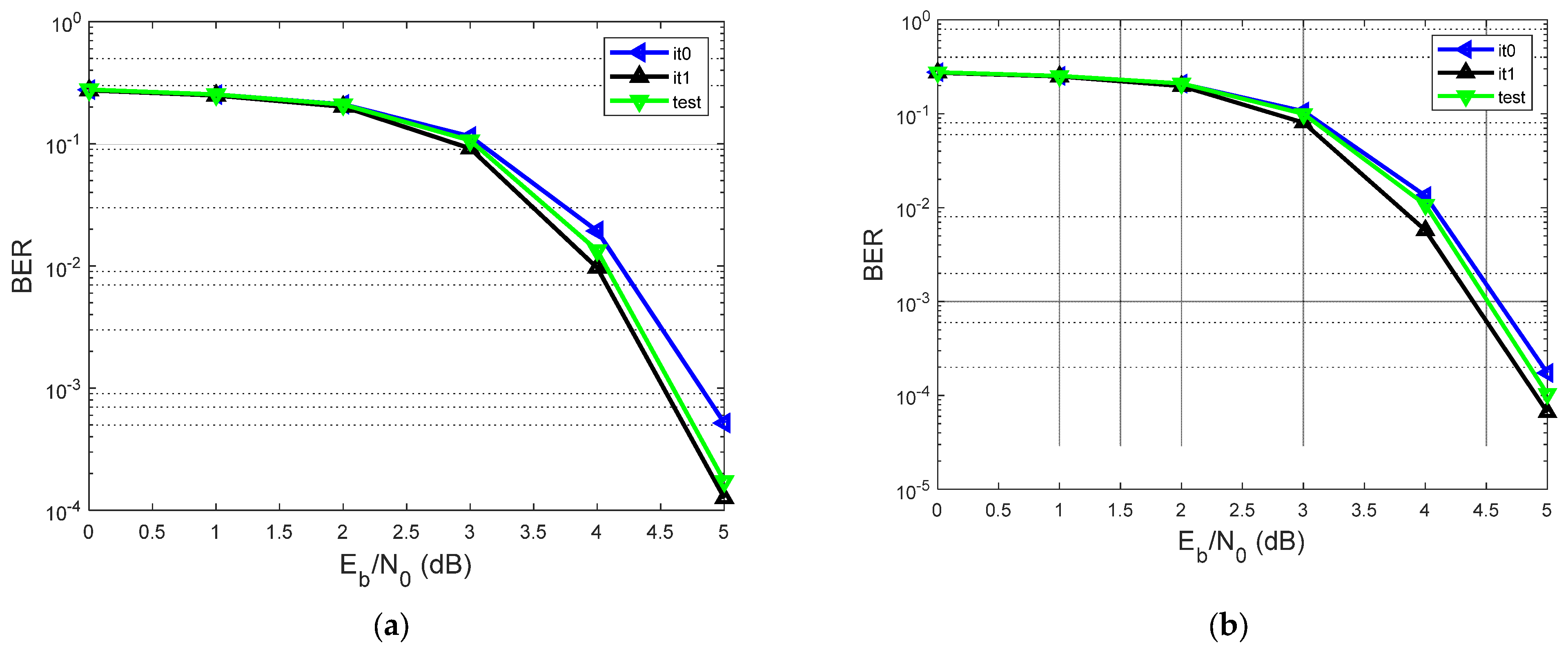
A. Analyzing the Contribution of the Log-MAP Equalizer of the Proposed System in Terms of BER vs. SNR, Considering h1 = [0.18 0.85 0.32]
Graphic/ScenarioIterative ReceiverMin-Sum LDPC Decoder
Figure 6a/1st Scenario2 iterations (it0 and it1)10 iterations at each iteration it0 and it1
Figure 6a/2nd Scenario1 iteration (test)20 iterations
Figure 6b/1st Scenario2 iterations (it0 and it1)20 iterations at each iteration it0 and it1
Figure 6b/2nd Scenario1 iteration (test)40 iterations
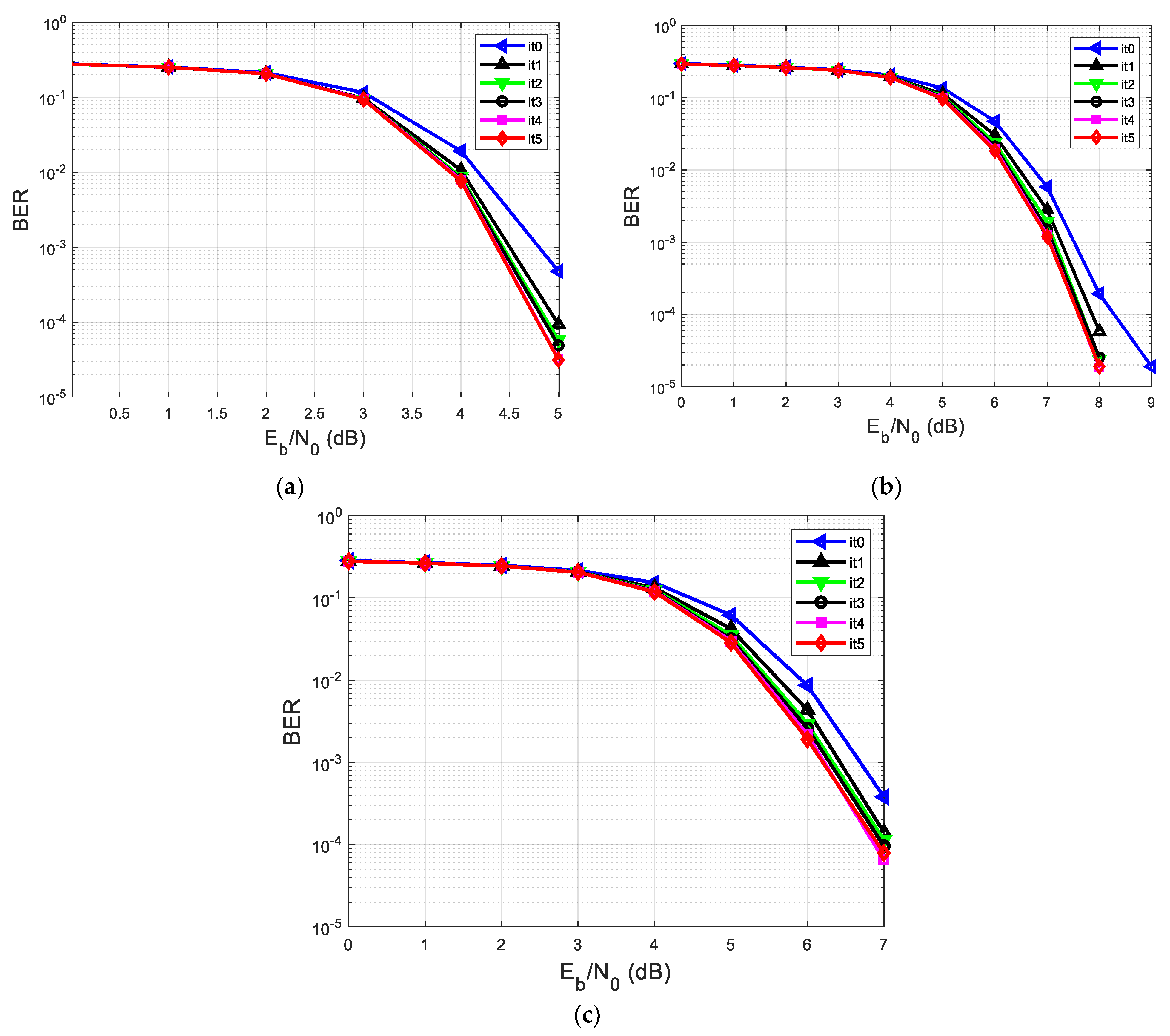
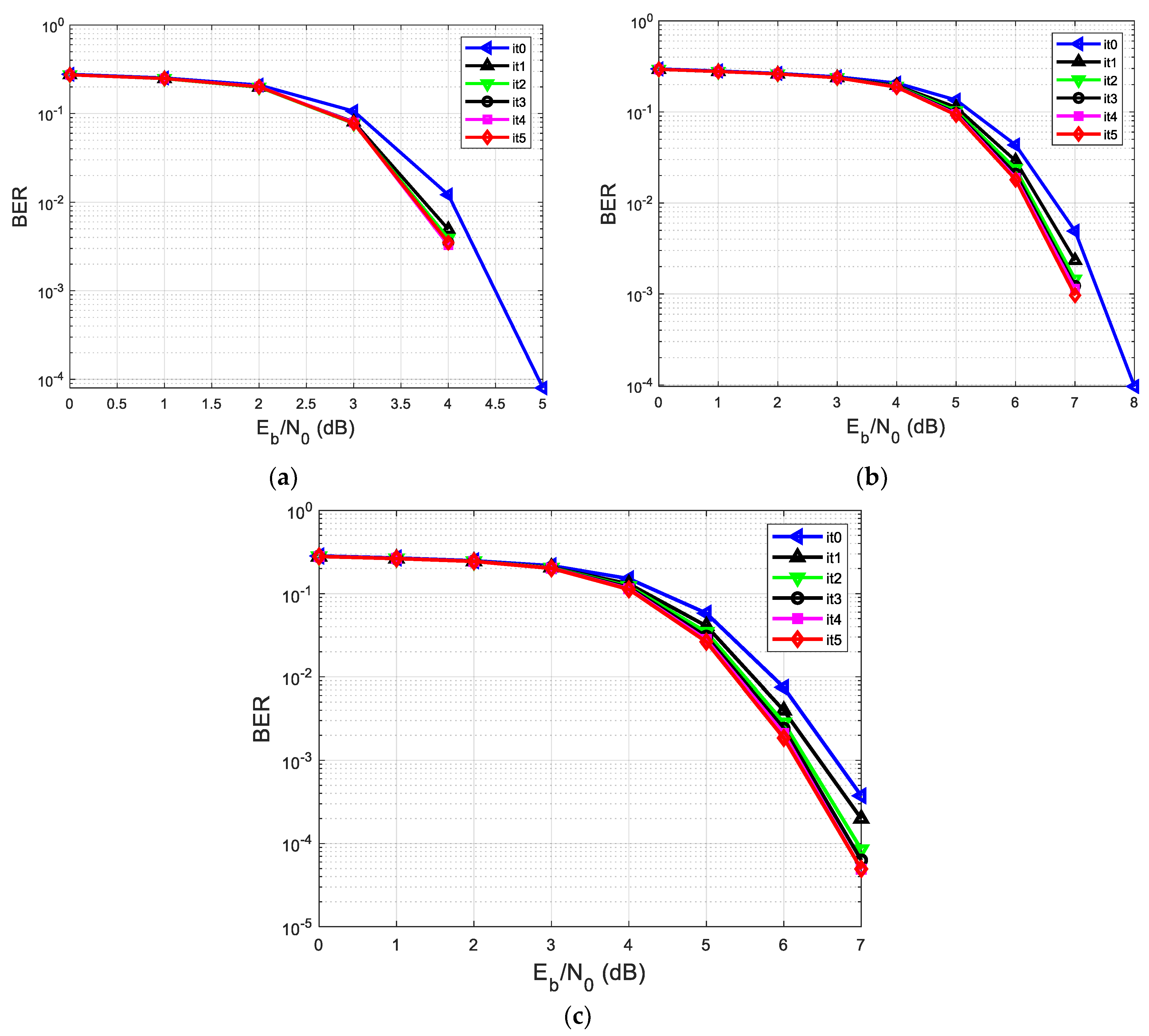
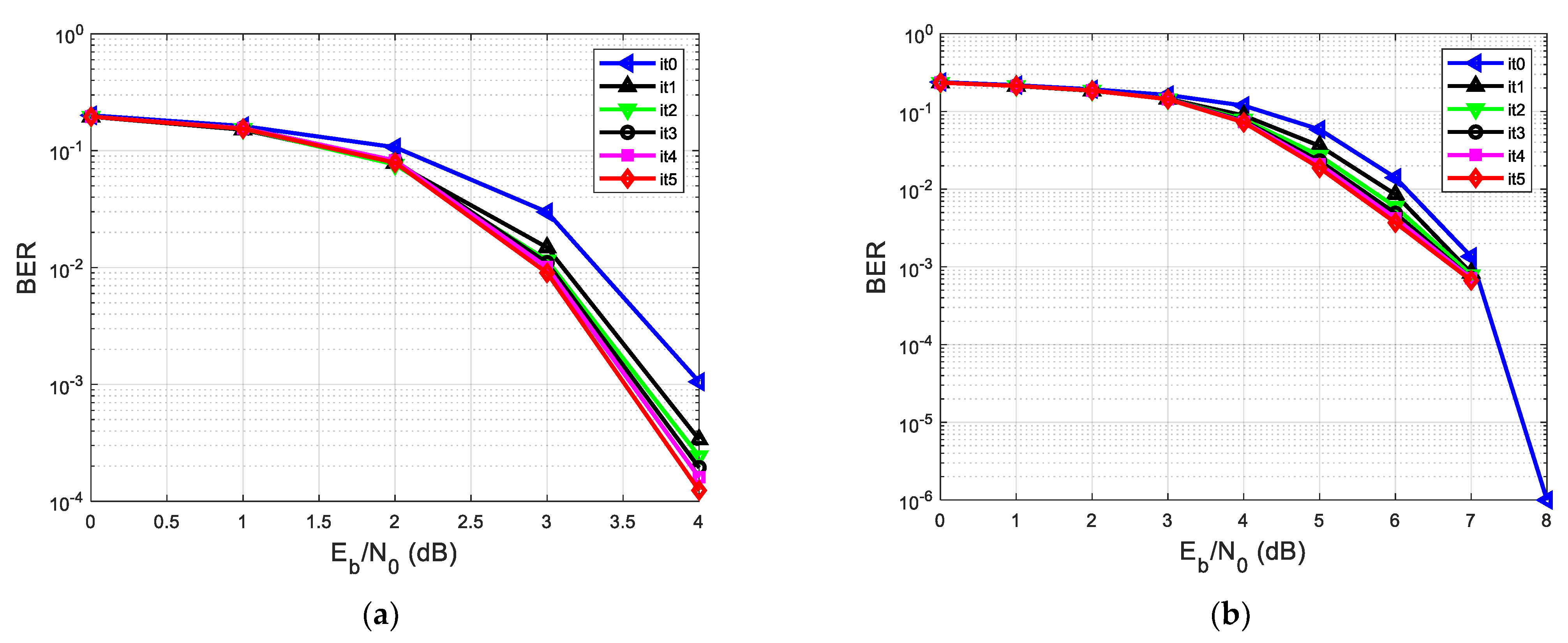
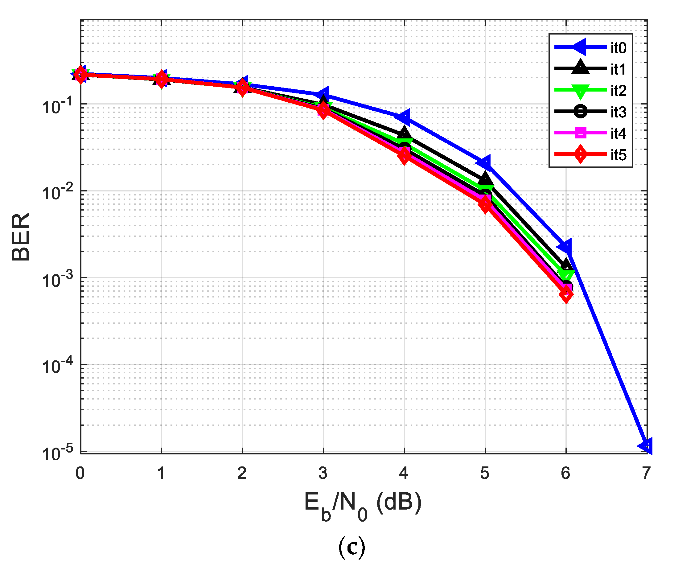
B. Analyzing the performances in terms of BER vs. SNR of the proposed system, considering different h’s
GraphicIterative ReceiverMin-Sum LDPC Decoderh
Figure 7a5 iterations10 iterationsh1 = [0.18 0.85 0.32]
Figure 7b5 iterations10 iterationsh2 = [0.302 0.725 0.456]
Figure 7c5 iterations10 iterationsh3 = [0.407 0.815 0.407]
Figure 8a5 iterations20 iterationsh1 = [0.18 0.85 0.32]
Figure 8b5 iterations20 iterationsh2 = [0.302 0.725 0.456]
Figure 8c5 iterations20 iterationsh3 = [0.407 0.815 0.407]
C. The proposed system was analyzed by comparing its performance in terms of BER vs. SNR with two other equalization and decoding systems.
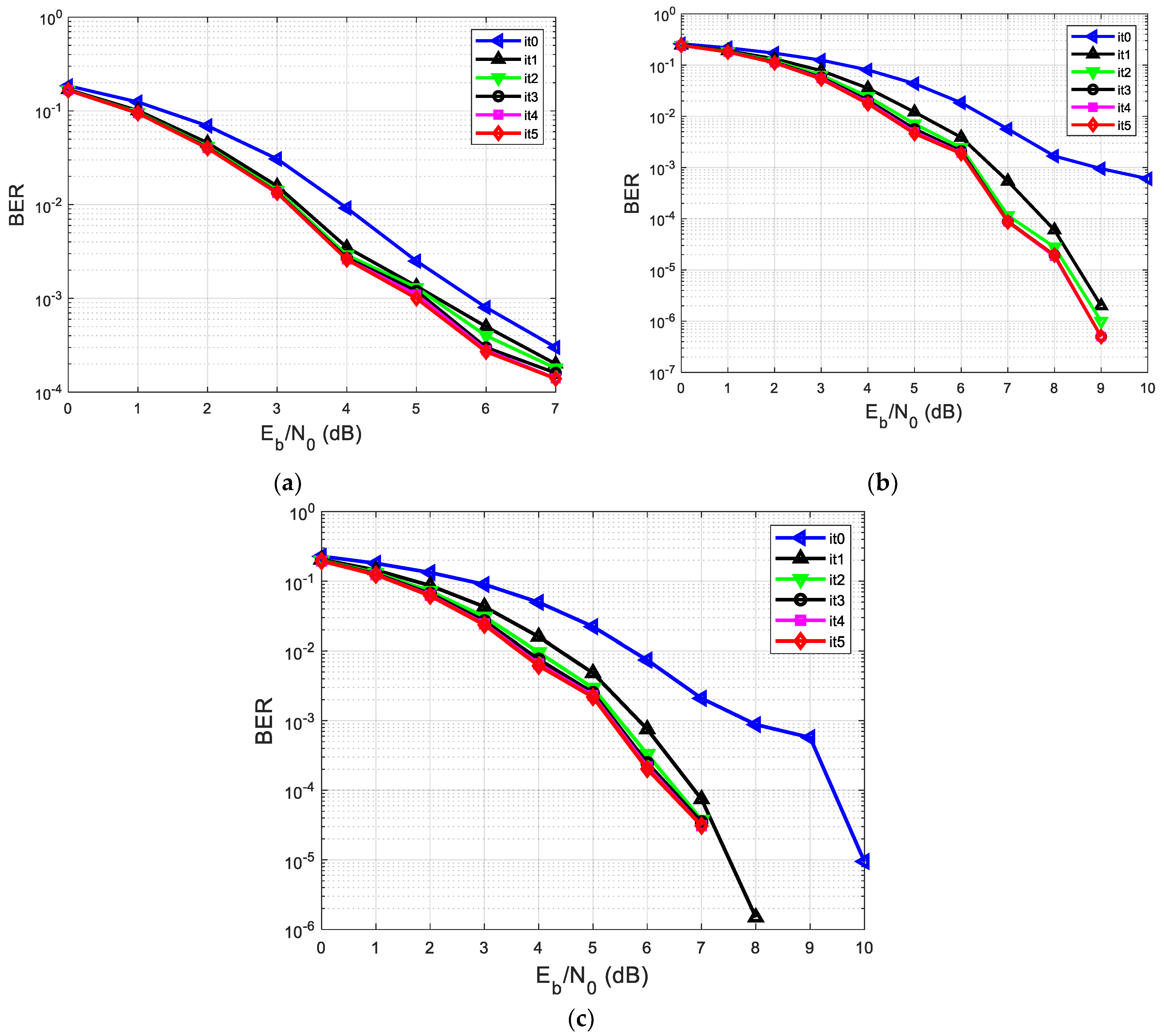
C1. The BER vs. SNR performance of the first system using classic turbo equalization, considering different h’s
GraphicTurbo equalization processh
Figure 9a5 iterationsh1 = [0.18 0.85 0.32]
Figure 9b5 iterationsh2 = [0.302 0.725 0.456]
Figure 9c5 iterationsh3 = [0.407 0.815 0.407]
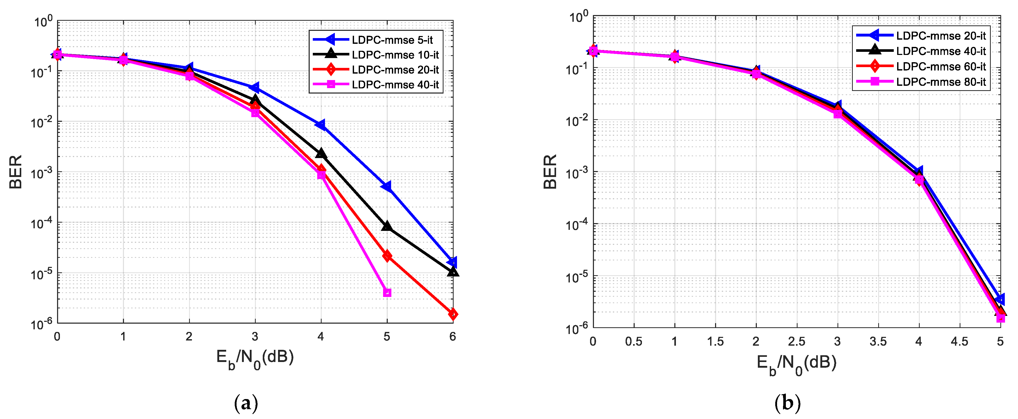
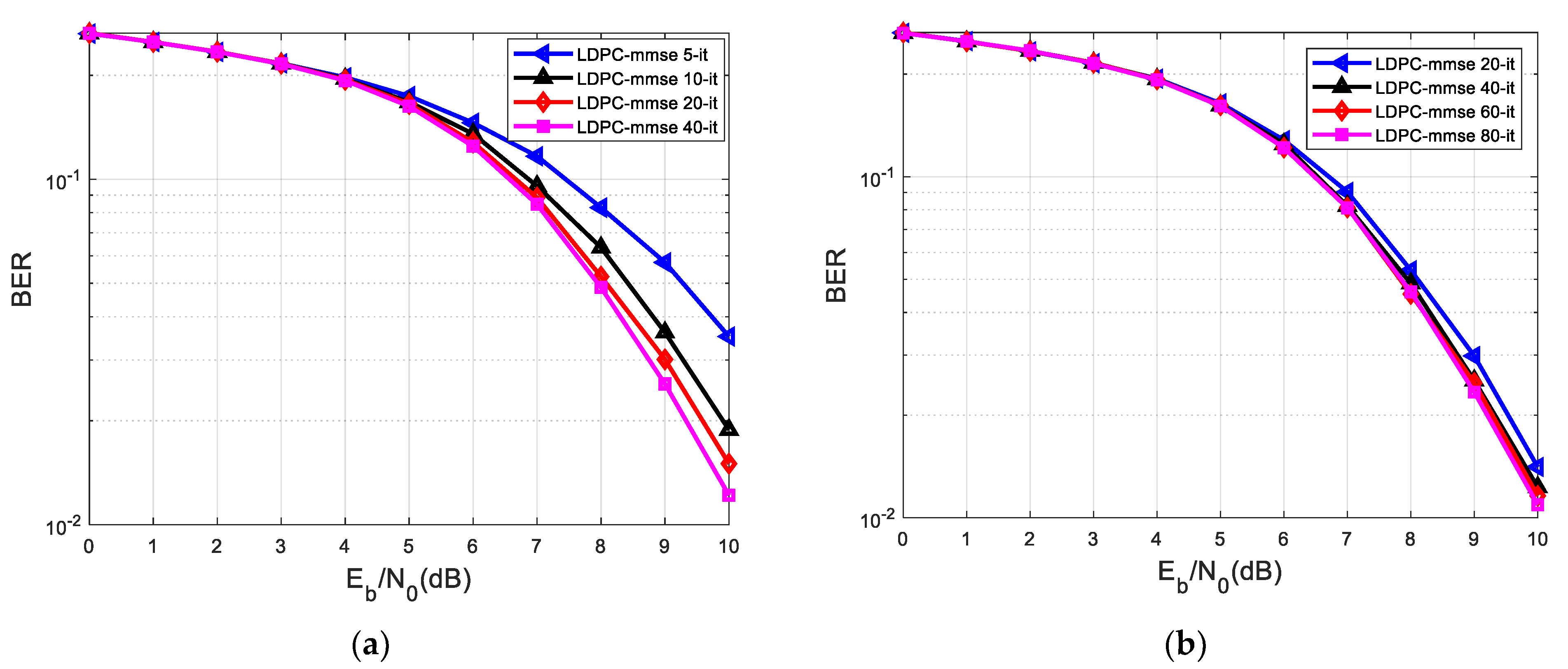
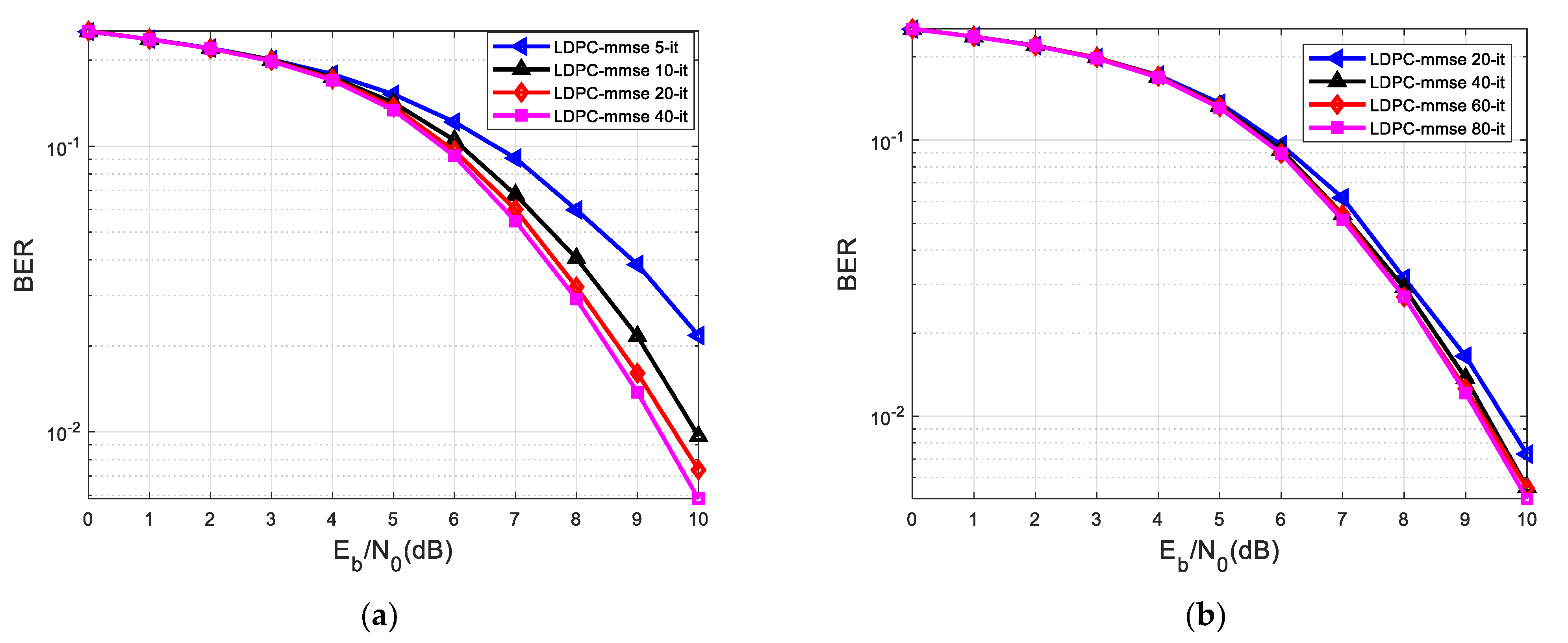
C2. The BER vs. SNR performance of the second system in which the equalization was performed separately before the decoding process using MMSE equalizer and LDPC decoder, considering different h’s
GraphicLDPC decoderh
Figure 10a40 iterationsh1 = [0.18 0.85 0.32]
Figure 10b80 iterationsh1 = [0.18 0.85 0.32]
Figure 11a40 iterationsh2 = [0.302 0.725 0.456]
Figure 11b80 iterationsh2 = [0.302 0.725 0.456]
Figure 12a40 iterationsh3 = [0.407 0.815 0.407]
Figure 12b80 iterationsh3 = [0.407 0.815 0.407]
D. Analyzing the performances in terms of BER vs. SNR of the proposed system, considering different h’s, when it was not punctured the first 2Zc bits (deviating from the standard)
GraphicIterative ReceiverMin-Sum LDPC Decoderh
Figure 13a5 iterations20 iterationsh1 = [0.18 0.85 0.32]
Figure 13b5 iterations20 iterationsh2 = [0.302 0.725 0.456]
Figure 13c5 iterations20 iterationsh3 = [0.407 0.815 0.407]
Table 2. BER vs. SNR in an ISI channel, at the SNR of 5 dB, using the proposed system for different impulse responses h.
5 it in the Iterative Process of Equalization and Decoding, 10 it in the LDPC Decoder
GraphichBER (Range)
Figure 7ah1 = [0.18 0.85 0.32]10−4–10−5
Figure 7bh2 = [0.302 0.725 0.456]10−1
Figure 7ch3 = [0.407 0.815 0.407]10−1–10−2
5 it in the iterative process of equalization and decoding, 20 it in the LDPC decoder
GraphichBER (range)
Figure 8ah1 = [0.18 0.85 0.32]0
Figure 8bh2 = [0.302 0.725 0.456]10−1–10−2
Figure 8ch3 = [0.407 0.815 0.407]10−1–10−2
Table 3. BER vs. SNR in an ISI channel, at the SNR of 5 dB, using turbo equalization and the equalization performed separately before the decoding process applying MMSE equalizer and LDPC decoding for different impulse responses h.
Turbo Equalization with 5 it.
GraphichBER (Range)
Figure 9ah1 = [0.18 0.85 0.32]10−3
Figure 9bh2 = [0.302 0.725 0.456]10−2–10−3
Figure 9ch3 = [0.407 0.815 0.407]10−2–10−3
Separate MMSE equalization and LDPC decoding with 40 it.
GraphichBER (range)
Figure 10ah1 = [0.18 0.85 0.32]10−5–10−6
Figure 11ah2 = [0.302 0.725 0.456]100–10−1
Figure 12ah3 = [0.407 0.815 0.407]100–10−1
Separate MMSE equalization and LDPC decoding with 80 it.
GraphichBER (range)
Figure 10bh1 = [0.18 0.85 0.32]10−5–10−6
Figure 11bh2 = [0.302 0.725 0.456]100–10−1
Figure 12bh3 = [0.407 0.815 0.407]100–10−1
Table 4. BER vs. SNR in an ISI channel, at the SNR of 5 dB, of the proposed system, turbo equalization, and separate MMSE equalization with LDPC decoding, for different impulse responses h.
5 it in the Iterative Process of Equalization and Decoding, 20 it in the LDPC Decoder
GraphichBER (Range)
Figure 8ah1 = [0.18 0.85 0.32]0
Figure 8bh2 = [0.302 0.725 0.456]10−1–10−2
Figure 8ch3 = [0.407 0.815 0.407]10−1–10−2
Turbo equalization with 5 it.
GraphichBER (range)
Figure 9ah1 = [0.18 0.85 0.32]10−3
Figure 9bh2 = [0.302 0.725 0.456]10−2–10−3
Figure 9ch3 = [0.407 0.815 0.407]10−2–10−3
Separate MMSE equalization and LDPC decoding with 40 it.
GraphichBER (range)
Figure 10ah1 = [0.18 0.85 0.32]10−5–10−6
Figure 11ah2 = [0.302 0.725 0.456]100–10−1
Figure 12ah3 = [0.407 0.815 0.407]100–10−1
Separate MMSE equalization and LDPC decoding with 80 it.
GraphichBER (range)
Figure 10bh1 = [0.18 0.85 0.32]10−5–10−6
Figure 11bh2 = [0.302 0.725 0.456]100–10−1
Figure 12bh3 = [0.407 0.815 0.407]100–10−1
Table 5. BER vs. SNR in an ISI channel, at the SNR of 5 dB, of our proposed system, puncturing or not the first 2Zc bits.
Puncturing the First 2Zc Bits
GraphichBER (Range)
Figure 8ah1 = [0.18 0.85 0.32]0
Figure 8bh2 = [0.302 0.725 0.456]10−1–10−2 or (1/2 × 10−1)
Figure 8ch3 = [0.407 0.815 0.407]10−1–10−2
Not puncturing the first 2Zc bits
GraphichBER (range)
Figure 13ah1 = [0.18 0.85 0.32]0
Figure 13bh2 = [0.302 0.725 0.456]10−1–10−2 or (1/9 × 10−1)
Figure 13ch3 = [0.407 0.815 0.407]10−2–10−3
Table 6. Comparing the performances in terms of BER vs. SNR of the proposed system to others published in the literature.
BER vs. SNR in an ISI Channel, at the SNR of 5 dB, Comparing the Proposed System to Others Published in the Literature
1st ComparisonhBER (Range)
The proposed system-5 it in the iterative process of equalization and decoding, 10 it in the LDPC decoder.h1 = [0.18 0.85 0.32]10−4–10−5(1/8 × 10−4)
The proposed system-5 it in the iterative process of equalization and decoding, 20 it in the LDPC decoder.h1 = [0.18 0.85 0.32]0
The MAP turbo equalizer implemented in [1] performs 10 iterations.h = [0.227 0.460 0.688 0.460 0.227]10−4
2nd comparisonhBER (range)
The proposed system-5 it in the iterative process of equalization and decoding, 20 it in the LDPC decoder.h1 = [0.18 0.85 0.32]0
The MAP turbo equalizer implemented in [8] performs 6 iterations.h = [0.227 0.460 0.688 0.460 0.227]10−3–10−4
3rd comparisonhBER (range)
The proposed system-5 it in the iterative process of equalization and decoding, 20 it in the LDPC decoder.h1 = [0.18 0.85 0.32]0
The implemented system in [28] designed with cooperative decoding between a BCJR detector and the spatially coupled low-density parity-check decoder performs 5 iterations.h = [1 1]10−4–10−5 (1/7 × 10−4)
Disclaimer/Publisher’s Note: The statements, opinions and data contained in all publications are solely those of the individual author(s) and contributor(s) and not of MDPI and/or the editor(s). MDPI and/or the editor(s) disclaim responsibility for any injury to people or property resulting from any ideas, methods, instructions or products referred to in the content.

