1. Introduction
With the development of indoor positioning and navigation systems and intelligent control technologies, rotary-wing unmanned aerial vehicles (UAVs) have gained increasing attention in various fields. Their simple structure, agile movement, and ability to hover in place make them widely applicable in indoor search, disaster site patrols, and fire extinguishing [
1,
2,
3]. In these applications, the rotary-wing UAV is typically used as an environmental perception and motion platform equipped with sensors. During its flight, it does not contact the external environment, lacking the ability to interact with it actively [
4]. By equipping UAVs with an aerial manipulator, effectively forming an aerial manipulator system, their active operational capabilities can be significantly enhanced, enabling them to perform tasks such as sample collection in extreme environments and transfer and delivery of hazardous materials, increasing the interaction capability between rotary-wing UAVs and the environment [
5].
Given that these aerial manipulator systems can perform operations in the air with high precision, they have emerged as a new research focus in robotics [
6]. Typically, the aerial manipulator comprises a rotary-wing UAV and a multi-degree-of-freedom manipulator. The rotary-wing UAV possesses high dimensionality, underactuation, and nonlinearity. When operating with a multi-degree-of-freedom manipulator, the overall dimensionality of the aerial manipulator system increases significantly, greatly expanding the application range of rotary-wing UAVs and providing broad prospects and societal implications [
7].
However, the manipulator’s accuracy of UAV positioning and target grasping currently requires improvement. To address this challenge, research has achieved the fast grasping capability of an aerial manipulator using a motion capture system (Vicon, Hauppauge, NY, USA) for UAV localization [
8]. However, achieving autonomous grasping relying solely on the UAV’s perception is yet to be fully realized. Especially in practical applications, the aerial operation of the manipulator is prone to losing target information, making it challenging to reconstruct three-dimensional spatial information and estimate real-time depth. Therefore, this paper analyzes the latest research and development trends in aerial manipulators and robot grasping. It focuses on key technologies during the grasping process of an aerial manipulator without the motion capture system (Vicon) in indoor environments. We propose a vision-guided autonomous positioning and control system for the aerial manipulator. The paper designs a hierarchical control system for the aerial manipulator’s pose and utilizes visual guidance for feature extraction and grasping pose estimation. Considering the range of motion during target grasping and the requirement to maintain a safe distance from the ground, a laser sensor is introduced to measure the distance between the aerial robot and the target object. An iterative algorithm is applied for target searching. Finally, the autonomous grasping functionality of lightweight cylindrical objects is achieved.
The main contributions of our study are as follows:
- (1)
We propose an integrated platform for a single-degree-of-freedom aerial manipulator that is low-cost, structurally compact, and easy to implement in hardware.
- (2)
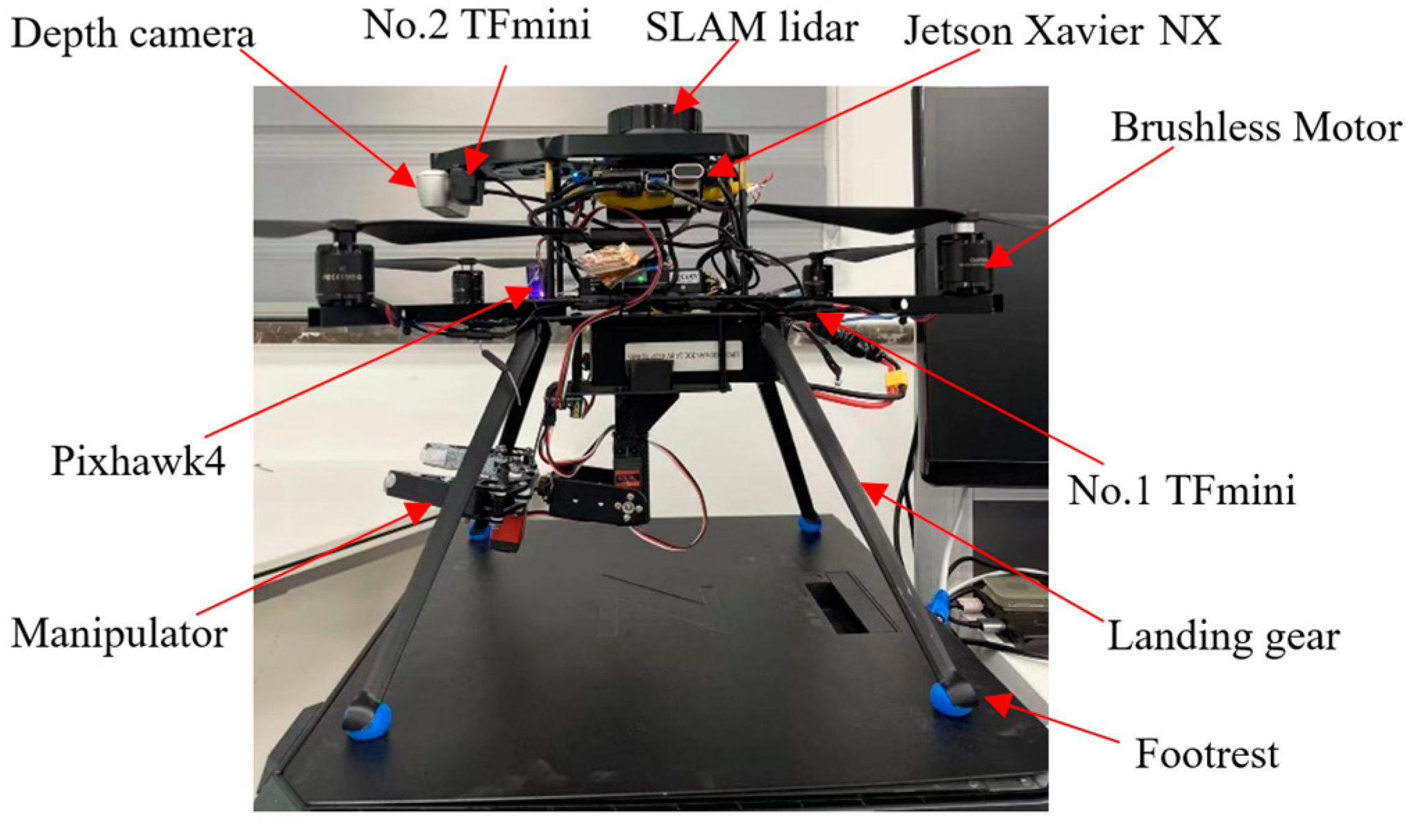
We design a hierarchical control system for an aerial manipulator with a flight control system for UAV attitude, position control achieved via Pixhawk4’s inner and outer loop PID algorithms, and an aerial manipulator with end-effector control controlled by Jetson Xavier NX.
- (3)
We propose a visual guidance algorithm for the real-time perception of target object position information by fusing a depth camera with laser-ranging data. Ultimately, a segmented grasping strategy is employed to achieve autonomous object retrieval. This system can effectively address target loss, 3D spatial information reconstruction, and real-time depth estimation during aerial operations.
- (4)
We propose a SLAM positioning method that integrates LiDAR and IMU, effectively addressing the low positioning accuracy of existing SLAM algorithms in the three-dimensional motion of UAVs, reducing cumulative errors, and enhancing map-building results.
This paper has five sections.
Section 1 introduces the background and significance of the aerial manipulator and summarizes relevant research.
Section 2 discusses the related work in the field of aerial manipulators.
Section 3 presents the hardware system of the aerial manipulator. The rotary-wing UAV and manipulator each have a control system with coupled interactions to achieve stable flight and precise positioning of the manipulator.
Section 4 provides a detailed analysis of the implementation approach for autonomous localization and grasping of the aerial manipulator.
Section 5 presents experimental analysis through simulations and physical demonstrations of target grasping tasks.
Section 6 presents the conclusions of our work.
2. Related Works
Research on aerial manipulator systems focuses primarily on the system’s structure, control system approach, and visual navigation strategy. For example, in the field of aerial manipulator system structure, Meng et al. [
9] used a 5-DOF aerial manipulator system to achieve the grasping of cylindrical objects. Suarez et al. [
10] designed a humanoid dual-arm aerial manipulator for grasping operations. Meanwhile, considering the high cost and risk involved in large infrastructure inspections, Hamaza et al. [
11] utilized a rotary-wing UAV equipped with a compact single-DOF manipulator to perform facility inspections and sensor installation. Yamada et al. [
12] researched a three-arm aerial manipulator using a flying robot for rope fixation and removal tasks and developed a manipulator structure suitable for complex operations. Peng et al. [
13] presented a novel aerial manipulator system with a self-locking universal joint mechanism. They also designed a dynamic gravity compensation mechanism and optimized the battery placement and gear ratio to minimize the weight imbalance during arm movements. Additionally, Zhang et al. [
14] designed a novel aerial manipulator structure with a 5-DOF manipulator and batteries placed at the front and rear of a quad-rotor UAV, respectively. This design expanded the workspace and minimized the center of mass offset. Experimental results demonstrated the successful capture of targets on a moving platform.
Regarding the aerial manipulator control system, Chaikalis et al. [
15] proposed an aerial manipulator system with a low-dimensional simplified mode. The system was validated through simulated aerial flights in various target-tracking scenarios. Furthermore, Chaikalis et al. [
16] addressed the issue related to team coordination for transporting payloads with aerial manipulator systems. A leader–follower setup was implemented to increase the system’s autonomy, where each manipulator’s gripper was equipped with force/torque sensors to enhance the UAV’s flight stability. The proposed control method was validated through simulation in the Gazebo environment. Meanwhile, Nguyen et al. [
17] presented the system design, modeling, and control of a chain-based aerial manipulator. This system provided a hybrid modeling framework for modeling the system in free-flight and aerial manipulation modes. Moreover, Nekoo et al. [
18] proposed a constraint-oriented design optimization method for dual-arm aerial robots to increase the robot’s workspace while reducing weight. In this configuration, the arms are separated from the aerial platform through long-distance linkages similar to pendulums, improving safety in human interaction scenarios.
Due to the development of machine vision and the decreasing cost of visual sensors, the research on utilizing vision sensors to obtain target object position information to estimate grasping poses in aerial manipulators has gained widespread attention. Luo et al. [
19] proposed a machine vision servoing method based on natural features to control an aerial manipulator for autonomous aerial grasping of target objects. Thomas et al. [
20] used an image-based visual servoing (IBVS) controller to maintain a simple gripper for autonomously grasping stationary objects. However, the depth estimation in the IBVS controller may be less accurate. Accordingly, Wu et al. [
21] adopted a UAV vision-based object detection method based on the YOLOv3 framework to identify target objects in complex environments using a gimbal camera. Meanwhile, Zhou et al. [
22] designed a three-dimensional point cloud extraction method that combines object detection and background subtraction to improve the grasp evaluation strategy. The proposed method was experimentally validated to estimate effective grasping poses for aerial manipulators. Chen et al. [
23] presented an IBVS control strategy for tracking and grasping moving targets in UAV systems. The method was validated through simulation and demonstrated effective tracking and grasping of moving targets. Hu et al. [
24] proposed an image-based underactuated aerial manipulator control scheme with an image space visual servoing controller on a dynamic horizontal plane. Moreover, it decoupled the attitude tracking task from visual impedance control to address the underactuated nature of the system. Ramon-Soria et al. [
25] described a system with dual manipulator arms with an RGB-D camera. The position information of the target object was obtained using artificial neural networks, and the grasping position and pose of the aerial manipulator were estimated by establishing a 3D model of the target object. Kim et al. [
26] proposed a guidance method based on IBVS comprising a passive adaptive controller based on position and velocity control to achieve autonomous grasping and transportation of target objects. Seo et al. [
27] introduced a vision-guided control method utilizing an image-based cylinder detection algorithm to identify elliptical surfaces and perform aerial operations. Kanellakis et al. [
28] used stereo-depth perception to extract the target’s position in the surrounding scene, obtaining the relative pose of the aerial manipulator and target object.
While this research indicates that the aerial manipulator system has become a research hotspot in robotics, the results are relatively singular. Indeed, the control and positioning navigation of the aerial manipulator system continue to face challenges when interacting with the environment. Regarding the structure of the aerial manipulator, numerous designs for the flight mechanical arm platform have been proposed for specific application scenarios [
9,
10,
11,
12,
13,
14]. However, these are limited by complex structures, low control accuracy, and insufficient robustness. Therefore, developing a flexible and highly expandable aerial manipulator structure is the main focus of this study.
Moreover, the aerial manipulator control algorithms proposed by previous studies require relatively complex kinematic and dynamic modeling, most of which are in the simulation stage and are challenging to apply in actual systems. Hence, real-machine flight has yet to be achieved [
12,
14,
15,
19,
21,
23]. Therefore, this paper focuses on developing an experimental platform for a UAV with a manipulator with lower-level control, positioning and navigation, and top-level application algorithms, ultimately achieving real-machine flight of target object grasping.
In addition, regarding the navigation and positioning strategy of the aerial manipulator, most apply the motion capture system (Vicon) [
26,
27,
28]. Although the Vicon system can significantly improve the positioning accuracy of flying robots, its high price limits the aerial manipulator’s application.
Accordingly, this paper proposes an effective aerial manipulator control method and positioning navigation method in an indoor environment without a Vicon system. Innovatively, a vision-guided algorithm is proposed to perceive the target’s position information in real time and adjust the attitude of the aerial manipulator. This study will guide other researchers in constructing experimental platforms and autonomous control of flight mechanical arms in the future.
4. Autonomous Positioning and Grasping
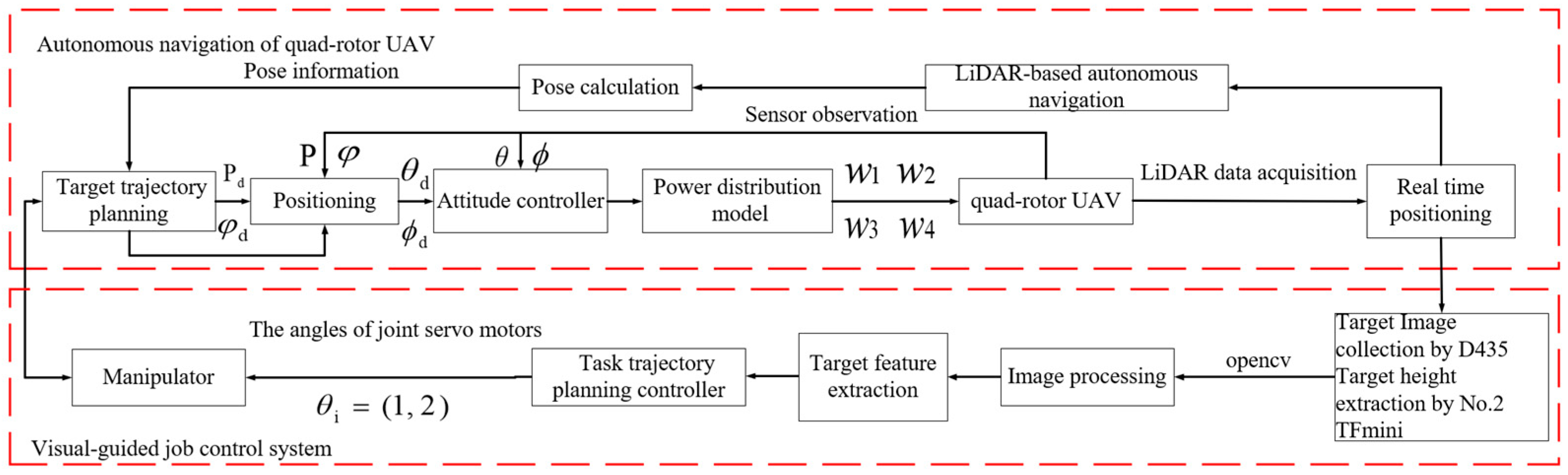
The designed aerial manipulator system achieves autonomous positioning and navigation through LiDAR-based SLAM map construction after the UAV takes off. It performs target search, gathers target object features using the depth camera D435 and laser sensor TFmini, extracts target feature information, obtains the target’s coordinate information, and transmits control signals to adjust the swinging angle of the manipulator to achieve accurate target grasping. Below, we discuss the SLAM-based autonomous positioning, visual navigation algorithm for grasping targets, and control method for aerial manipulator operations guided by vision.
4.1. SLAM-Based Autonomous Positioning and Navigation System
The autonomous positioning of quad-rotor UAVs is a requisite for indoor obstacle avoidance, path planning, and grasping. Localization is the primary challenge; currently, quad-rotor UAV localization primarily falls into two categories [
31,
32]: obtaining position information through the UAV’s perception or relying on external devices, such as the motion capture system (Vicon). However, the Vicon systems are expensive and require specialized environments, restricting the application range of aerial manipulators.
Therefore, we integrated low-cost sensor data, such as LiDAR, IMU, with a laser altimeter module. SLAM [
33,
34] was utilized to achieve high-precision pose estimation and environment mapping and realize indoor autonomous navigation for aerial manipulators.
4.1.1. System Framework of the LiDAR SLAM-Based Positioning Method
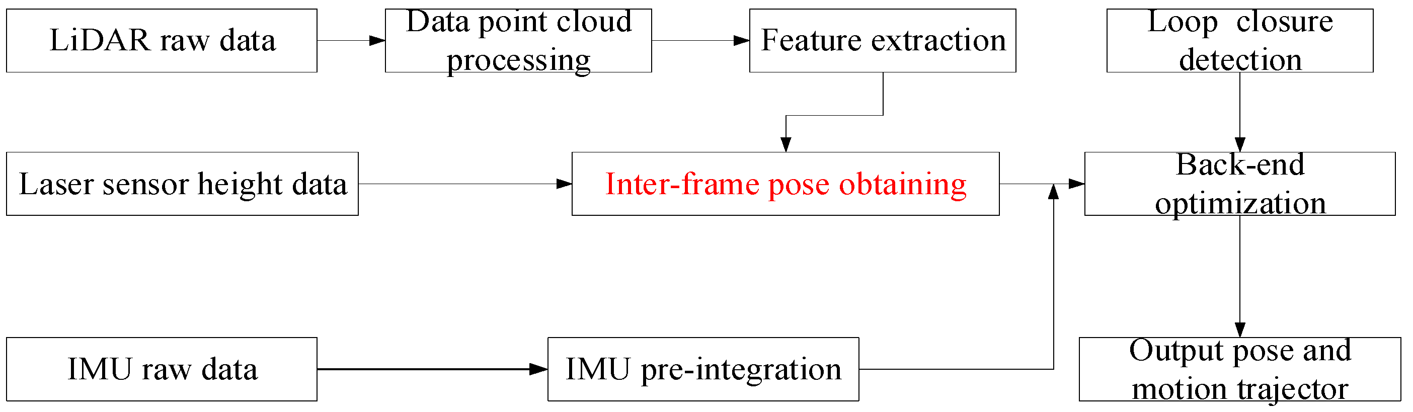
The SLAM-based positioning method combines the high-precision autonomous positioning requirements of the aerial manipulator, comprising three parts: LiDAR odometry [
35], IMU module, and back-end optimization. The overall framework is illustrated in
Figure 5.
4.1.2. LiDAR Odometry
First, the raw data collected by the LiDAR sensor is processed to handle point clouds. During the UAV flight, laser beams may hit screens, sky, or other non-reflective surfaces, causing laser degradation and refraction, resulting in ineffective reflection information. Such laser points must be removed using a point cloud library tool. Subsequently, a breadth-first traversal method is employed to downsample the point cloud, reducing the number of laser points and eliminating uncertain objects in the environment. Equation (2) computes the curvature of laser points [
36]:
where
represents points in the current frame under the coordinate system of the LiDAR,
denotes the set, and
represents the curvature of the point. The laser points are arranged in descending order based on their curvature values. Larger curvatures indicate lower smoothness and correspond to corner points, while smaller curvatures indicate higher smoothness and correspond to line points. Here, two curvature thresholds,
and
, are set in descending order. Neutral points are eliminated based on Equation (3), resulting in the current frame’s point cloud
, as follows:
Second, we perform inter-frame matching—a crucial step for constraining the pose relationship between frames. We use a point-line registration approach [
37] to improve computational efficiency and ensure real-time performance. Corner points and line points extracted from the current frame point cloud
are respectively labeled as
and
. The corner points and line points extracted from the previous frame are denoted as
and
, respectively. Since the UAV is in motion from times
to
, the associated pose of each point is adjusted to the corresponding time. The laser points from each frame are projected onto the initial time, denoted as
and
. Corner point matching involves selecting a point in
and identifying the two closest points in
to form a distance constraint between a point and line. The line point matching involves selecting a point in
and identifying the three closest points in
to form a distance constraint between a point and plane. We use the Levenberg-Marquardt optimization method to identify the rotation and translation matrices that minimize these two distance constraints. This yields the pose transformation
obtained through inter-frame matching.
4.1.3. IMU Module
A LiDAR sends out all data from the same frame simultaneously. However, the UAV is constantly in motion, causing the position of the LiDAR’s coordinate system to change. This movement introduces distortions to the collected LiDAR data. Assuming the UAV undergoes uniform motion, the IMU module performs distortion correction on the LiDAR data. The IMU can provide angular and linear acceleration measurements. By considering the installation position of the IMU and LiDAR, the transformation relationship between the IMU and LiDAR coordinate systems can be determined. The point cloud is then transformed to the IMU coordinate system. The pose transformation between two consecutive IMU frames is represented by Equation (4) and denoted as
:
The transformation of the LiDAR pose at time
relative to the LiDAR pose at time
is given by Equation (5):
4.1.4. Back-End Optimization
The loop closure detection module [
36] determines whether a loop closure has occurred in the system by calculating the Euclidean distance between the current frame and previous keyframes. The keyframes that meet the criteria are stored in a subset (i.e., subkeyframes). For each point in the subkeyframes, a corresponding point is searched in the current frame to form a distance constraint. We then use the ICP (iterative closest point) algorithm [
38] to compute the optimal rotation and translation matrices that satisfy the constraints. The transformation parameters are solved by constructing an error function using the matched points, aiming to minimize the error, as shown in Equation (6):
where
is a point in the original point cloud
;
is the point in the historical point cloud that has the minimum Euclidean distance with
; and
represents the number of points in the subset of keyframes.
By using the obtained transformation matrices and , we update the point cloud in the subset of keyframes. We then continue to construct the error function until the result is smaller than the set threshold or the iteration reaches the specified limit.
4.2. Visual Navigation Algorithms for Grasping Targets
4.2.1. Vision-Guided Laser Range Measurement
The visual guidance-based laser range measurement used in this paper is shown in
Figure 6. First, the two-dimensional image information of the target object is captured with the D435 depth camera with a 120° wide field of view to facilitate rapid target object identification. Next, the edge detection algorithm is applied using OpenCV to extract the contour information of the target object’s edges. The NO. 2 TFmini sensor is employed to collect real-time height information for the UAV and target object to determine the height information
of the UAV relative to the target object. Finally, by transforming the coordinates between the target object and the camera coordinate system, the position relationship between the UAV and the target object is established, facilitating the adjustment of the manipulator’s various joint servo angles to achieve precise grasping.
4.2.2. Target Grasping Analysis
By integrating the depth camera and laser ranging data, the UAV’s and target object’s coordinate information is achieved. Combined with the UAV’s own pose data, the current three-dimensional spatial position of the target object in the world coordinate system is obtained.
Figure 7 presents the target object grasping scenario in the aerial manipulator system, including the world coordinate system W, camera coordinate system C, and target coordinate system. Hereafter, we describe the process of transforming the target’s coordinates from the camera coordinate system to the world coordinate system.
First, the camera’s attitude can be obtained from the UAV’s onboard inertial navigation system. The obtained camera attitude quaternion can be denoted as
, and its corresponding rotation matrix can be represented as [
39]:
Assume that the coordinates of the target object in the world coordinate system and camera coordinate system are represented as
and
, respectively.
denotes the translation matrix between the world coordinate system and the camera coordinate system, obtained using the camera coordinates provided by the UAV’s inertial navigation system. Therefore, our algorithm ultimately calculates the coordinates of the target object in the world coordinate system as follows:
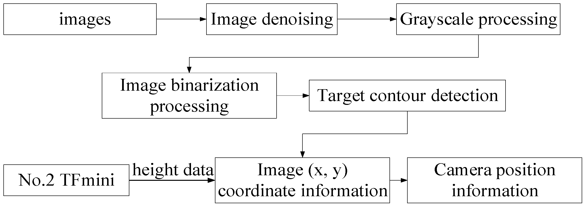
4.2.3. Visual Guidance Algorithm
We propose a novel grasping method for aerial manipulators based on a visual guidance algorithm. This model utilizes a front-mounted depth camera D435 on a rotary-wing UAV to detect and recognize the positional information of the target object, enabling the adjustment of the aerial manipulator’s pose angles. The implementation process of the visual guidance algorithm is depicted in
Figure 8, and the specific steps are as follows:
Step 1: Utilize the VideoCapture class in OpenCV to capture the video stream from the camera and read the images.
Step 2: Apply Kalman filtering to denoise the captured image, reducing image distortion caused by UAV vibrations.
Step 3: Process the denoised image by converting it to grayscale and performing binary thresholding. Utilize the Canny algorithm to obtain the edge information of the image.
Step 4: Obtain the two-dimensional coordinates of the target object image and integrate the height data acquired from the No. 2 TFmini to obtain the camera position information. Subsequently perform coordinate transformation to obtain the target object’s coordinate information, enabling real-time adjustment of the aerial manipulator’s attitude.
4.3. Control Method of Visual Guidance Based on the Aerial Manipulator
The complete process for implementing the visual-guided aerial manipulator’s control method is below (
Figure 9).
Step 1: The quad-rotor UAV takes off and uses LiDAR for SLAM positioning and map construction. It performs path searching and planning for the target object while the aerial manipulator remains in the initial folded posture.
Step 2: The UAV searches for the target object within the working range of the manipulator using a depth camera. It utilizes OpenCV to recognize and detect the two-dimensional coordinate information of the target object. The UAV performs a small-scale iterative search if the target object is undetected. If the target object is detected, the UAV lowers its height and utilizes the No. 2 TFmini for real-time detection of the vertical distance from the depth camera to the target object. Based on the coordinate transformation, the three-dimensional position information of the target object is obtained.
Step 3: The target object’s positional information is continuously updated in real time until it reaches the operational grasping range. The manipulator’s pose is adjusted, with the arm hanging down to enter the pre-grasping pose. Considering the relative position of the UAV to the target object, as well as the shape and size of the object to be grasped, the grasping range of the manipulator is set. The aerial manipulator enters the grasping range, and the trajectory planning and control system outputs the desired motion angles for each servo joint involved in the grasping process to the manipulator’s servo controller. Finally, the aerial manipulator completes the grasping of the target object.
Step 4: After the UAV completes the grasping process, it continues to climb. During its ascent, the real-time height information from the No. 2 TFmini () is collected. If fluctuates within a range of 3 cm above or below a reference value (), the target object is within the grasp range of the mechanical claw, and the grasping is successful. In such a case, the UAV flies towards the designated target delivery point. However, if is significantly larger than , the grasping has failed, and the UAV returns to searching for the target object.
Step 5: The UAV proceeds toward the designated target delivery point for searching. If the search is successful, the UAV descends to the predetermined placement height to deliver the target object. If the search is unsuccessful, the UAV continues with a small-scale iterative search. By maintaining a constant UAV altitude and implementing a delayed hovering approach, a certain buffer time is provided to the manipulator control system to make angular adjustments, ensuring synchronization between the manipulator control system and the flight control system.
Step 6: After the aerial manipulator successfully delivers the target object, the manipulator returns to its initial state and proceeds to the landing point.
5. Experimental Results
Experimental analysis and validation were conducted on the visual-guided hierarchical control and autonomous positioning system for the aerial manipulator based on simulation and physical real-world experiments.
5.1. Simulation Experiment for LiDAR SLAM-Based Autonomous Navigation of UAVs
In this study, an autonomous navigation and path planning experiment for a LiDAR-based SLAM system was built on the robot operating system (ROS) platform. The operating system used was Linux Ubuntu 18.04, and the experiment employed the physical simulation platform Gazebo and the data visualization tool rviz for real-time monitoring. The testing environment was set up and obstacles were added to simulate the autonomous navigation system of the aerial manipulator.
First, in the simulator, the origin of the world coordinate system was taken as the initial position, along with a specified take-off height. At the beginning of the simulation, the UAV slowly ascended to the specified height and performed LiDAR scanner localization and map construction in the world coordinate system. The map data topic was visualized and displayed by rviz. The target object position was specified on the map and published as a topic. The UAV system in Gazebo then subscribed to this topic to obtain the optimized path planning algorithm for the shortest path and track to the position above the target object.
Figure 10 shows the result of the SLAM autonomous navigation map building of a UAV from takeoff to near the target object in the Gazebo simulation environment.
Figure 10a represents the laser radar scanning, where green and purple indicate obstacles.
Figure 10b shows the UAV automatically planning its navigation based on the obstacles, with the planned flight path depicted as the red route. Based on the flight trajectory, the UAV readily avoided obstacles during flight, with no obvious swaying traces and a relatively smooth overall flight path.
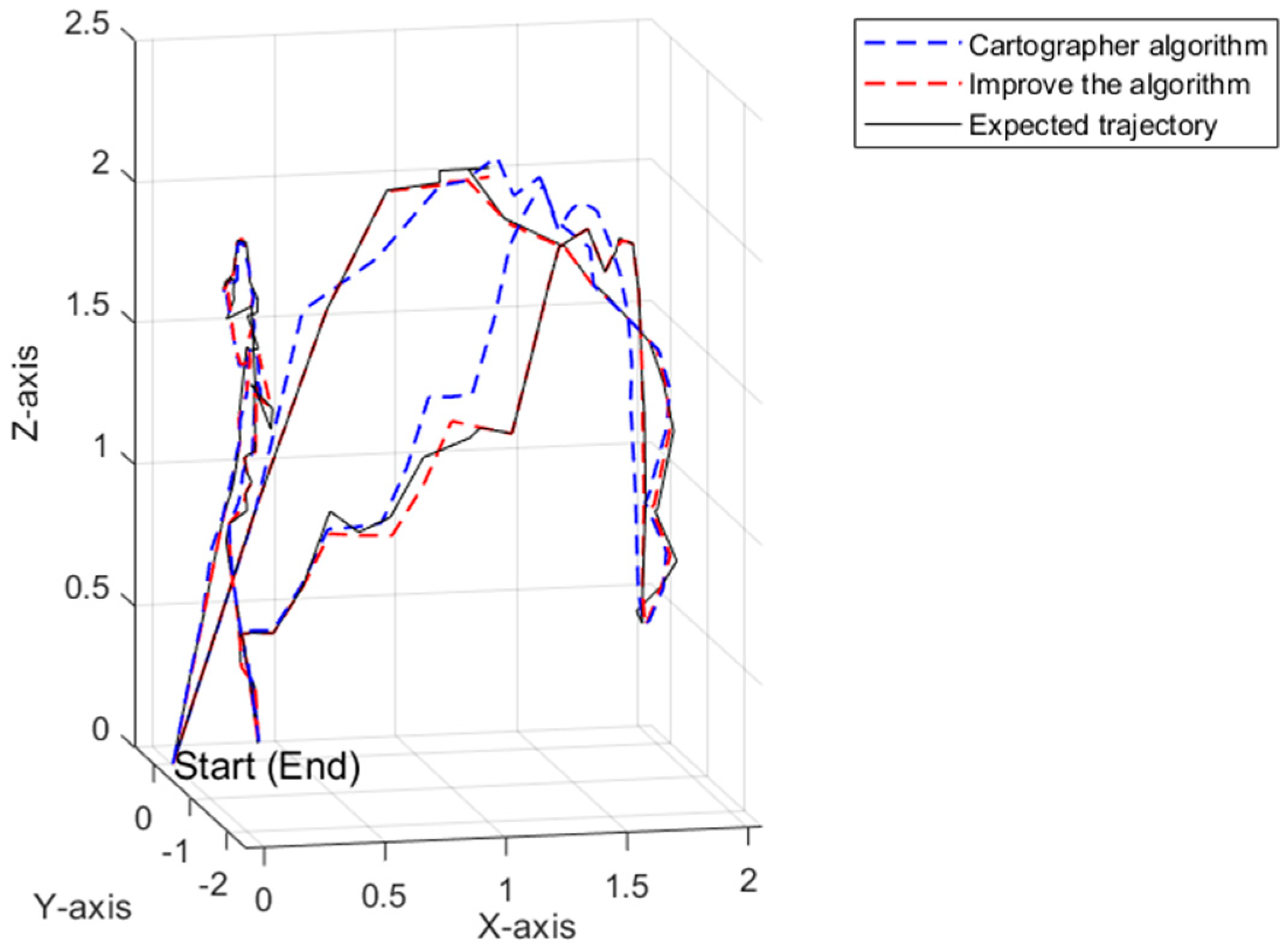
Based on the fused IMU laser SLAM algorithm proposed in this paper, the trajectory map of the UAV was constructed. This algorithm was compared with the classical laser SLAM algorithm Cartographer [
39]. The Cartographer algorithm and the expected trajectory exhibited a relatively large cumulative drift error, while the trajectory obtained by the algorithm proposed in this paper had a relatively smaller cumulative drift error (
Figure 11).
5.2. Motion Test of the Aerial Manipulator
Before performing tasks, the vision-guided aerial manipulator required a series of debugging operations, including flight controller calibration, ESC initialization, PID parameter configuration, camera activation, and setting the initial position of the manipulator. At the system’s initial takeoff, the uneven terrain may have introduced uncertainty and error into the subsequent task execution. To further enhance the success rate of the mission, in our practical testing, we selected a flight scenario with dimensions of 4 m × 5 m × 4 m and a flight speed of 0.6 m/s.
Additionally, testing and experimental analysis of the motion process were conducted for the aerial manipulator system to ensure that the quad-rotor UAV maintained stable aerial operational capability and flight performance after mounting the manipulator.
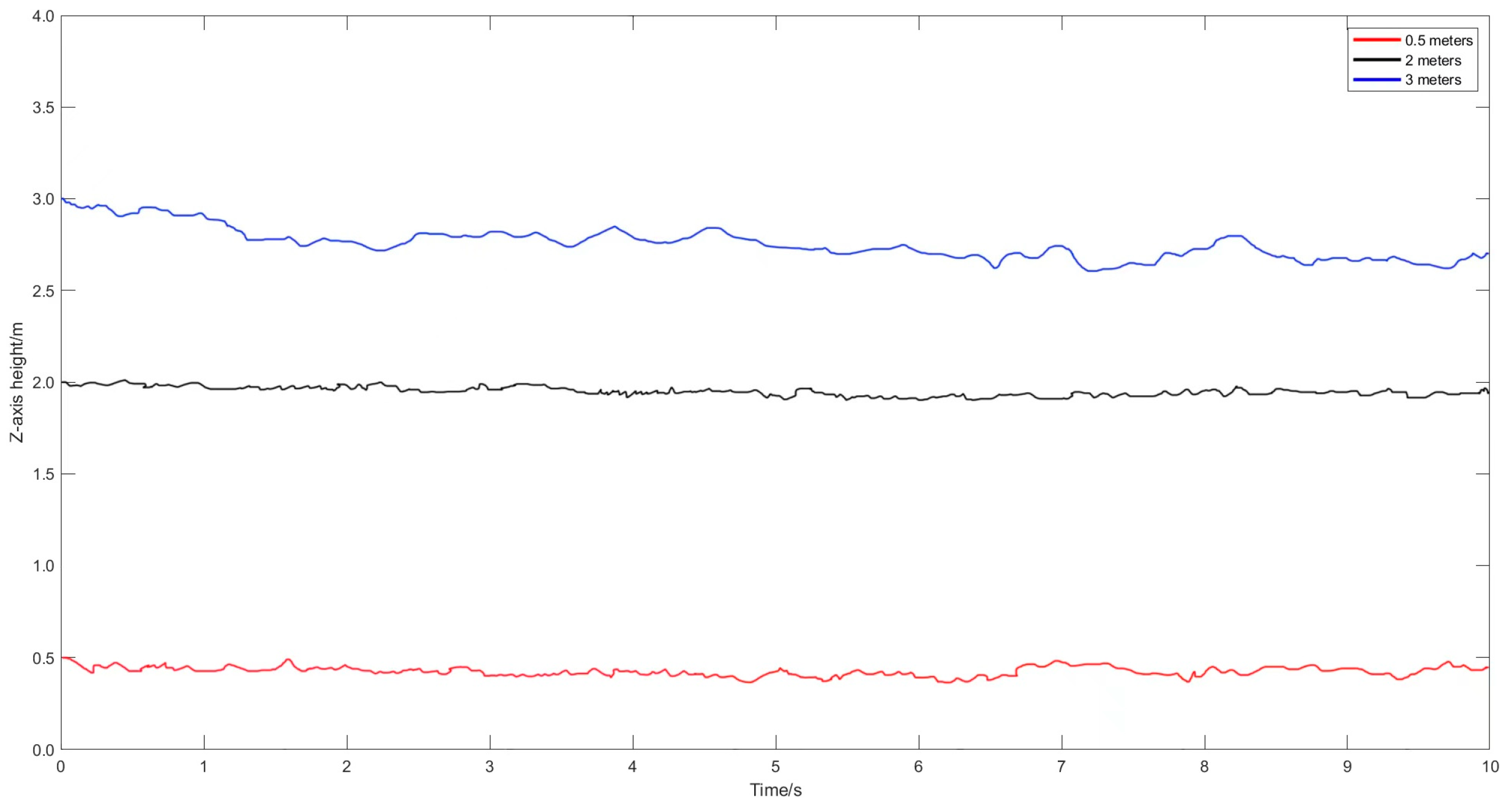
First, the flight stability during hovering was tested.
Figure 12 provides height variation curves for the manipulator in the z-direction at hover heights of 0.5 m, 2 m, and 3 m. At a hover height of approximately 0.5 m, a slight fluctuation occurred in the UAV’s attitude due to ground effects. However, when flying at ~2 m, the flight was stable. Meanwhile, at a hover height of ~3 m, significant attitude variation occurred. Therefore, the selected hover height for this study was 2 m.
Second, to minimize the impact of manipulator motion on the stability of the flying platform, tests were conducted on the servo motor speeds. The testing scenario involved controlling the servo motor speed of the manipulator through the upper computer while the UAV was in stationary hover.
Figure 13 provides the attitude angle variation curves of the servo motor at different speeds (35, 48, and 55 rpm). Moreover, the manipulator moved slowly at 48 rpm, and under conditions that ensured the operational efficiency of the manipulator, the impact of its motion on flight stability was minimized.
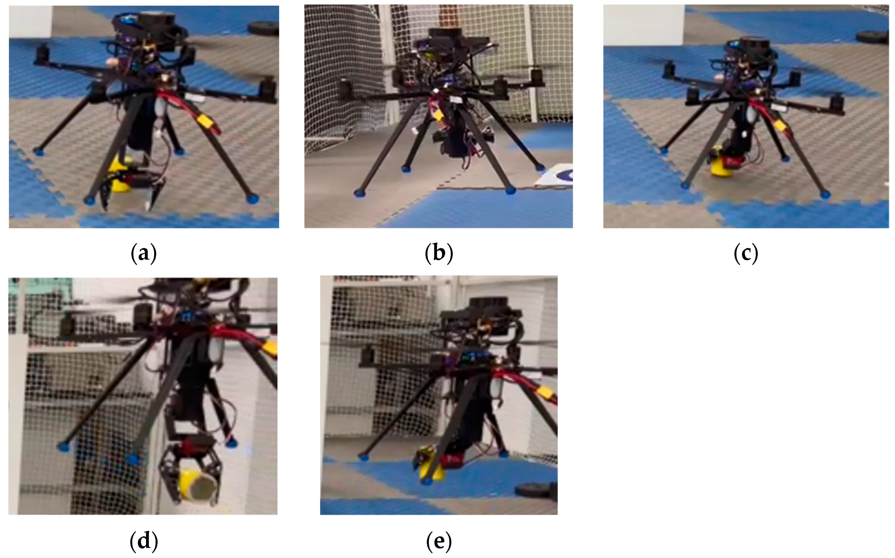
As shown in
Figure 14, for the grasping task of the aerial manipulator, a segmented grasping strategy was applied. Specifically, five poses were designed, including the initial pose, pre-grasping pose, grasping pose, flight pose in operation, and delivery pose. The specific process was as follows:
Initial flight pose (
Figure 14a): The UAV took off and approached the target object, while the manipulator remained in the initial retracted state. During the target search process, the SLAM mapping and scene reconstruction were performed with LiDAR, followed by autonomous positioning and target object search.
Pre-grasping pose (
Figure 14b): The UAV navigated to the target object’s position using LiDAR-based SLAM for localization. The visual guidance system was activated to identify the target object. The UAV hovered and descended in altitude while the manipulator adjusted its position in advance. It vertically descended to approach the target object in the optimal pose for grasping. The manipulator reached the pre-grasping pose.
Grasping pose (
Figure 14c): The aerial manipulator iteratively searched the target object, while the No. 2 TFmini continuously detected the height information between the UAV and target object. Once the grasping height of the aerial manipulator fell within the threshold range, the mechanical gripper quickly closed to grasp the target object.
Flight pose (
Figure 14d): After the aerial manipulator grasped the target object, it flew away from the operating point and proceeded to the target delivery location.
Delivery pose (
Figure 14e). The aerial manipulator reached the target position for delivery, and then took off to land at the original point.
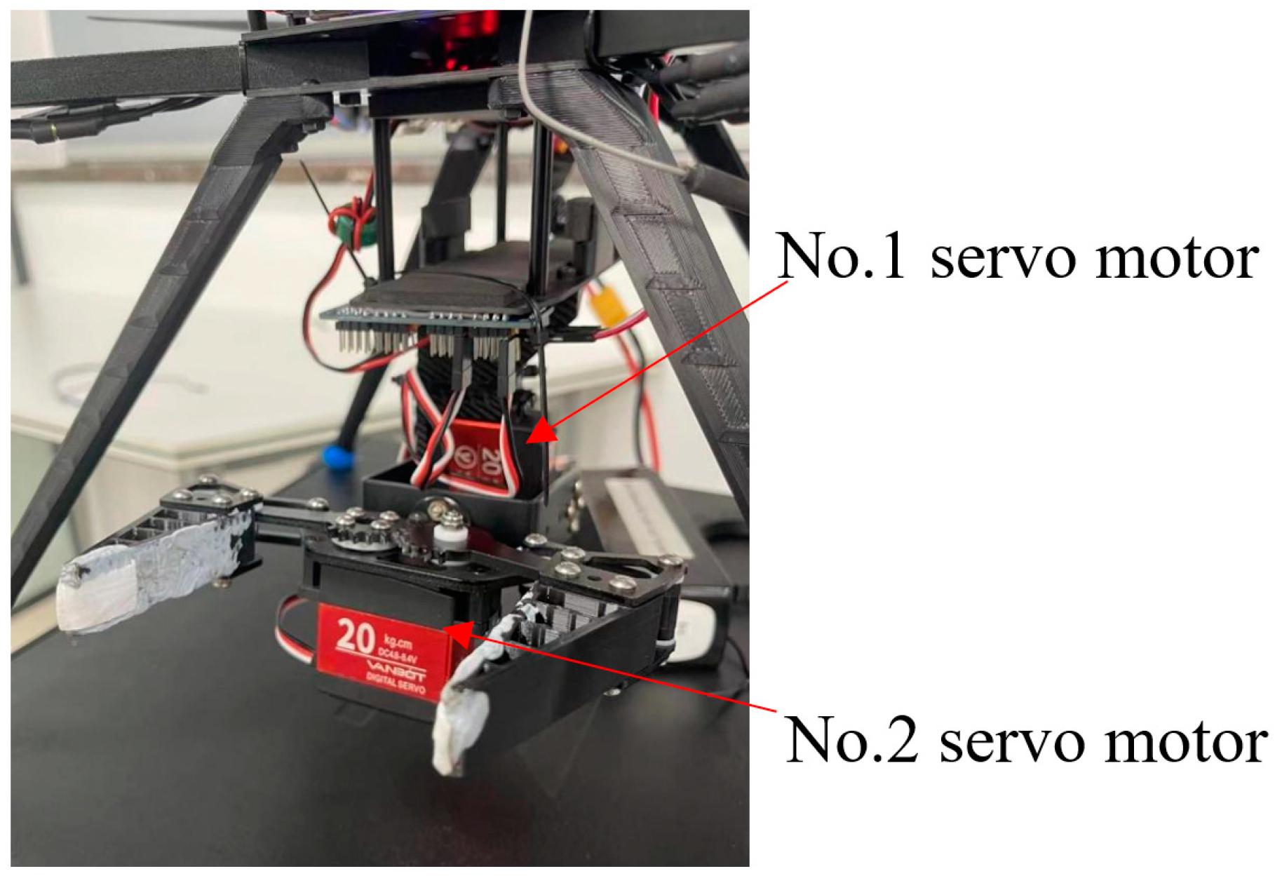
During the entire motion testing experiment of the aerial manipulator, to ensure the system’s safety during the grasping operation, the angles of the two servos in the manipulator and gripper were repeatedly tested and optimized. The angle values of the two servos were defined as
and
, where
represents the pitching action of the manipulator and
represents the grasping action of the gripper. The corresponding output values
and
for the five poses during the operation of the flight robotic arm are shown in
Table 2.
From the analysis of the operational motion experiment, it was concluded that the aerial manipulator system was capable of autonomously positioning and navigating throughout the flight. It also performed target object grasping through visual guidance. Moreover, it accurately controlled the UAV’s attitude angles while maintaining a constant spatial position, possessing excellent spatial operational capabilities.
5.3. Attitude Analysis of the Aerial Manipulator
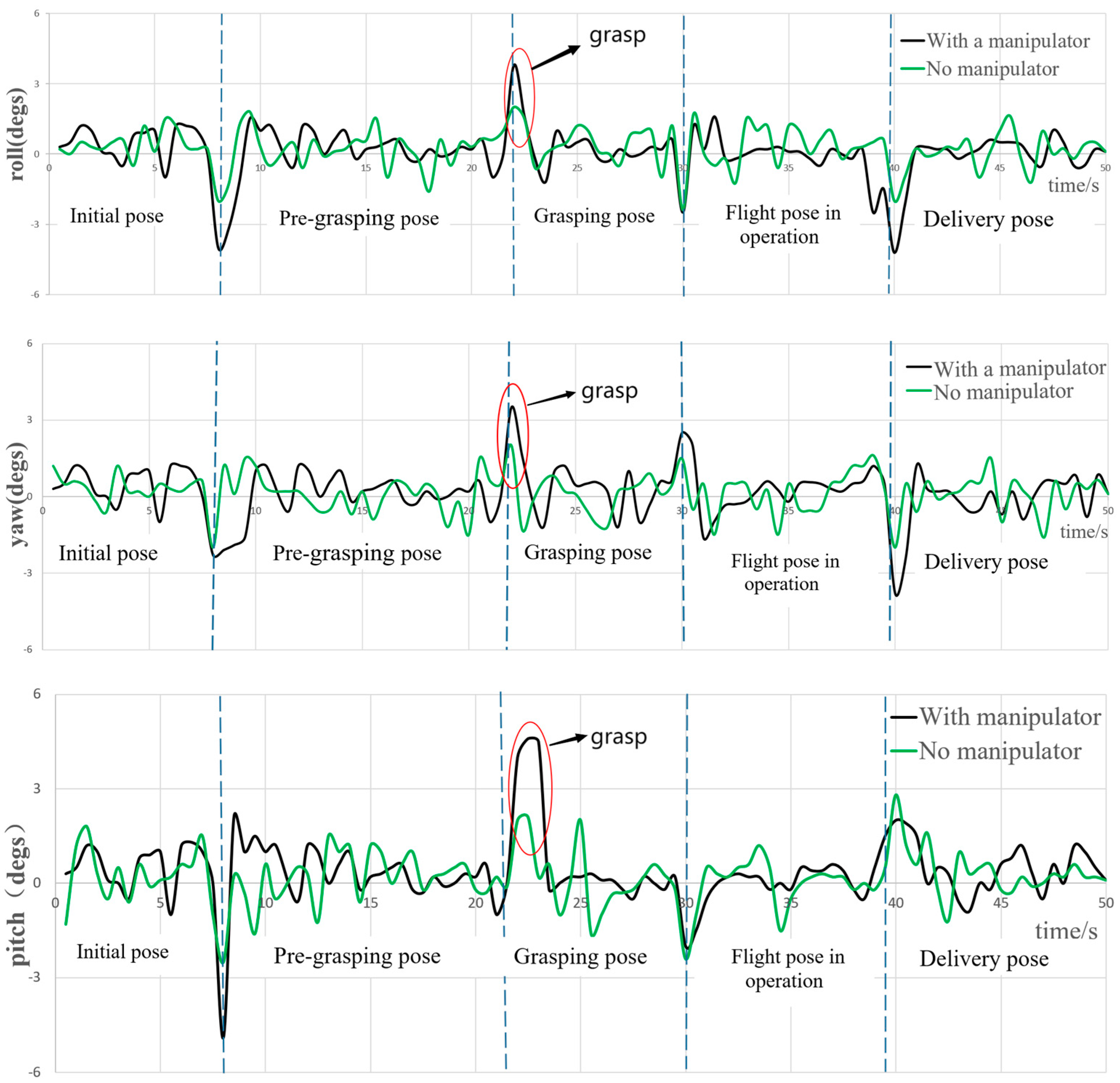
Rotary-wing UAVs are complex, nonlinear, and underactuated systems. When equipped with a manipulator to perform tasks, the system’s dynamics are influenced by factors such as motion velocity, angles, and payload mass. This can cause deviations in the attitude and positioning of the UAV, leading to mission failures, accidents such as collisions with the ground, and even crashes. Therefore, in this study, flight data was recorded to execute the five operational motion poses. The attitude information of the UAV was analyzed and compared before and after mounting the operational aerial manipulator. This analysis aimed to validate the operational stability of the proposed aerial manipulator system.
As shown in
Figure 15, the aerial manipulator took off from 0 s to 8 s and moved along an autonomous navigation path in search of a target object. During the motion, the UAV’s attitude angles exhibited relatively small fluctuations before and after mounting the manipulator, which fell within the normal range of attitude angle variations for indoor flights. Between 9 s and 21 s, the UAV reached the target object and visually guided itself toward it. The manipulator descended vertically into the pre-grasping pose. Due to the disturbances caused by the manipulator, the center of gravity of the entire flight system can change, resulting in dynamic instability and slightly larger fluctuations in the attitude angles. However, the roll and yaw angles had relatively smaller fluctuations. With the manipulator, the range of fluctuation for the roll angle was within ±4°, and the range for the yaw angle was within ±2.5°. However, the pitch angle exhibited larger fluctuation within ±5°. This was due to the movement of the manipulator in the XOZ plane from the initial pose to the pre-grasping pose, significantly affecting the pitch angle stability of the aerial manipulator system.
Between 22 s and 30 s, the aerial manipulator entered the state of grasping the target object. Compared to the state without the manipulator, the presence of the manipulator resulted in larger variations in the attitude angles due to the weight of the grasped object. In particular, the pitch angle experienced fluctuations, however, generally remained within ±5° for control. The mechanical gripper completed the grasping action before and after 22 s (as indicated by the red circle in
Figure 15). Subsequently, the aerial manipulator ascended to the operational flight pose, reached the target location for delivery, and landed at the destination. Throughout the flight process, the variations in the attitude angles can be controlled within ±5°, which falls within the normal fluctuation range. This also demonstrates the good stability of the designed operational aerial manipulator system.
In summary, the aerial manipulator system designed in this study can generally ensure the global stability of the system during flight operations in the five poses. It can respond to external forces caused by grasping the target object, allowing the UAV to maintain stability. Additionally, it does not produce significant position drift and exhibits robustness in underactuated conditions.
5.4. Position Analysis of the Aerial Manipulator
To further validate the effectiveness of the proposed method, we recorded the position data of the operational aerial manipulator system, including the initial, grasping, and delivery states.
As shown in
Figure 16, the aerial manipulator took off and entered the target search state at approximately 2 m. During the iterative search for the target object, the positional information along the x, y, and z axes of the aerial manipulator fluctuated. At approximately 22 s, when the target object grasping was completed, considerable fluctuation occurred in the positional information along the x, y, and z axes. The height information along the z-axis was 35 cm, while the physical height of the aerial manipulator was 30 cm. Hence, the grasping height was within an acceptable operational range, confirming that the proposed method exhibits good control effectiveness.
5.5. Control System Performance Analysis of the Aerial Manipulator
The performance validation of the aerial manipulator control system was conducted, with a primary focus on stability and disturbance resistance analysis. Moreover, the system was compared to the quaternion-based PID algorithm in the open-source Pixhawk flight controller (
https://docs.px4.io/main/zh/config_mc/pid_tuning_guide_multicopter_basic.html, accessed on 8 June 2023). The motion of the manipulator during tasks, such as target object grasping, transportation, and delivery, generates reactive forces that introduce disturbances. Additionally, the state estimation process of the flight robotic arm introduces measurement noise. Therefore, this study performed trajectory tracking experiments for the aerial manipulator’s periodic swinging during straight-line UAV flight in the presence of dynamic disturbances. Two joint servos of the aerial manipulator swung periodically between θ
1 = 0°, θ
2 = 70°, and θ
1 = 115 °, θ
2 = 45° (
Figure 17).
Compared to the quaternion-based cascaded PID algorithm used by Pixhawk, the aerial manipulator platform exhibited significant improvement in positional error in all three coordinate axes. When the manipulator underwent periodic swinging during UAV flight, the UAV’s positional and attitude errors using the proposed method were noticeably lower than those of the Pixhawk algorithm. These experiments demonstrate the effectiveness and robustness of the control method proposed in this paper.


