1. Introduction
Currently, there is great interest in subsurface sounding systems with high-frequency electromagnetic radiation. Such systems enable non-destructive underground exploration for industrial and archaeological purposes; searching for underground utilities; the detection of electrical wiring and pipes laid along buildings; the detection of defects in building structures; and diagnostics of road and railway tracks. Deformation of the road surface and the soil under it significantly affects the service life and safety of roads. The cause of the premature wear and destruction of the road surface is design errors, the violation of construction and repair technologies, the quality of the materials used, water logging of the roadway embankment with ground and surface waters, and, as a result, shedding of the soil. To predict the timing of repairs and the high-quality reconstruction of roads, it is necessary to have a complete understanding of the structure of the pavement, including the geological structure of the underlying soil. Therefore, it seems extremely important to develop technologies for operational diagnostics of the state of the railway embankment, capable of examining long sections of the road in a short time. Standard inspection methods call for taking samples of the roadbed under test, either by drilling and coring or by removing some of the top layers, to visually determine the internal condition of the structure. The disadvantages of these methods are their invasiveness and pinpoint determination of the thickness of the roadway. Due to the fact that the laying of the roadbed can be uneven, this method does not allow determining the thickness of the roadbed over the entire laid section. Compared with other methods of non-destructive testing, the use of GPR provides high accuracy and speed of determining inhomogeneities in the underground environment, as well as low cost. Currently, non-destructive testing methods for studying various soils are based on a variety of physical phenomena, such as acoustic methods (sonic and ultrasonic frequencies) [
1]. With ultrasound, it is impossible to answer the question about the actual dimensions of the object. The ultrasonic method imposes the need to maintain direct contact with the surface being examined. The investigated medium must be elastic; otherwise, ultrasound examination is impossible due to the rapid attenuation of the waves. Another is infrared thermography [
2]. The main disadvantages of infrared thermography include the fact that the difference in temperature between the desired object in the embankment and the environment is often too small to fix it. The bottom line is, similar to the ultrasonic method, the thermal method is used for radio sounding of rails and sleepers, but it is ineffective for the embankment. Scattered magnetic flux method [
3] is effective for searching for defects in steel objects, such as rails. However, the shallow scanning depth of the embankment and the high risk of signal distortion by the rails make this method unsuitable for our purposes. Optical methods [
4,
5] and methods based on eddy currents [
6] are very widely used due to the wide variety of possibilities for obtaining information. The possibility of their use for external control does not depend on the material of the object. This method, in fact, is a study of the surface of the embankment; however, it is not suitable for subsurface sounding. Methods based on electromagnetic radars [
7] have been carefully studied. Furthermore, machine learning has been proposed for various methods, such as: support vector machine (SVM), neural network (NN), K-nearest neighbors (KNN), hidden Markov model (HMM), naive Bayes method (NB), decision tree (DT), etc. [
8,
9]. However, the accuracy of traditional machine learning algorithms depends on manually selected features, so the above algorithms work correctly only on certain georadargrams.
At present, numerous studies are aimed at developing technologies for applying metamaterials to antenna systems for various purposes [
10,
11,
12,
13,
14,
15,
16]. However, despite the intensive development of this topic, the technology was narrowband for a long time, and only in the last five years, work has been carried out on the use of metamaterials with an extended operating frequency band. Existing antenna systems for georadio sounding have a number of disadvantages, for example the radiation pattern of traditional antennas is determined by the relative size of the aperture. A large aperture is required to obtain a needle chart. There are difficulties with matching the elements of antenna arrays, and this and other circumstances lead to high material costs. Metamaterials provide an unprecedented ability to manipulate electromagnetic waves and enable technology for new devices ranging from flat lenses that focus light beyond diffraction to coatings that can mask an object. However, narrow bandwidths and high internal losses due to the resonant properties of metamaterials make it difficult to expand their scope. New design approaches seek to turn perceived dispersion disadvantages into assets that enhance device performance. One way is to create a focusing device from a metamaterial with a negative refractive index.
Modern methods for creating metamaterials are being intensively developed, but so far, little attention has been paid to important effects due to the near-field interaction of the basic elements of metamaterials. According to the methods proposed in the literature for creating metamaterials, many experimental prototypes of composite structures with negative permittivity and magnetic permeability have been developed to date. Thus, the work of Md Bellal Hossain, Mohammad Rashed Iqbal Faruque, and others [
17] proposes the creation of a material based on a resonant structure of the RLC circuit type. In this work, negative refractive readings were obtained at resonant frequencies of 2.02, 6.985, 9.985, and 14.425 GHz. In [
18], a metamaterial was presented, which is a printed circuit board with a resonant pattern on it. Like the previous version, it is an RLC type, which is based on the resonant negative value of the dielectric and magnetic permeability. This structure changes its value of dielectric and magnetic permeability with a change in the substrate, as well as with a change in the wave incidence on this structure. Negative values were obtained at resonances at frequencies of 10.2 and 4.3. In addition to negative metamaterials, materials with a zero refractive index are also being created [
19]. The modern literature provides examples of the creation of focusing devices with an operating frequency of 3.5 GHz [
20]. The miniaturization of antenna systems with improved signal transmission was considered in [
21]. It was claimed that the operating frequency range of such antennas extends from 7 to 8 GHz (1 GHz band). The reduction in overall dimensions and improvement in performance using metamaterials was demonstrated in the work of M.J. Alam et al. [
22] for widely used GPS, WLAN, and WiMAX antennas. The study of the decrease in the effective scattering area of an object covered with a metamaterial was carried out in [
21,
23,
24,
25]. It is noted that this decrease occurs only when the wavelength is 632.8 nm. In addition, the following are actively discussed in the literature: the possibility of synthesizing nanoscale circuits using metamaterials [
26], the creation of optical-range metamaterials based on nanotechnologies [
27], and the problems of improving the characteristics of already existing strip antennas. However, the papers [
26,
27,
28] also dealt with the use of not very broadband metamaterials. Therefore, for example, from the analysis of the content of [
28], it follows that the antenna described in it becomes more efficient only at two resonant frequencies of 12.5 GHz and 14.25 GHz. Metamaterials are also used in the space industry, as in [
29], where the calculations of a horn antenna were presented. The use of a metamaterial with a real part of the refractive index equal to 0.5 makes it possible to improve the characteristics of the antenna, namely: to reduce the level of side lobes, reduce the width of the main lobe directional pattern, and increase the radiation maximum.
At the beginning of 2022, several interesting papers on the use of metamaterials in antenna technology were published. Thus, in [
30], the effect of a gyro-bianisotropic metamaterial on the input impedance of a dipole antenna was considered. The article [
31] is devoted to modeling the SRR structure and demonstrated the presence of magnetic resonance at a frequency f = 23.69 GHz, which is of interest for antennas supporting wireless microwave point-to-point communication systems (for example, in satellite systems). The original metamaterial structure for a dual-band subwavelength resonator antenna with a high gain for frequencies of 3.75 GHz and 5.66 GHz was presented in [
32]. Metamaterials are also used in the design of antennas for 5G communication systems; for example, article [
33] describes an antenna operating at frequencies ranging from 28.5 GHz to 30.5 GHz and having overall dimensions of 2.58
. From the analysis of the literature, we can conclude that the worldwide scientific community is paying great attention to the creation and application of metamaterials in antenna technology; many works on the creation of metamaterials with various configurations and geometries have been presented.
The authors of the article are looking for new ways and approaches to improve the quality of georadiograms [
34], so the results of the created antenna array based on the developed “PlastRam” antenna element [
35] have already been presented. These results show a high accuracy in determining the thickness of the pavement layer. However, there are problems associated with the definition of the boundaries of the layers of the roadway of automobile and pedestrian roads. There are also difficulties in sounding the embankment of railways. To improve the created TerraZond geosounding system, it was proposed to improve the characteristics of the georadar by focusing the electromagnetic waves. For this, a metamaterial based on composite elements in the form of rings was used. A material with the same structure, but made of metallic elements, had a negative refractive index [
36].
2. Materials and Methods
Let us consider the case of a plane wave falling onto a single hollow cylinder with an annular cross-section located in the plane of the electric field component. A hollow cylinder with an annular cross-section is made of a composite with an electrical conductivity of 3.4 × 10 S/m, with an outer diameter of 8 mm and an inner diameter of 4 mm. The composite material was obtained by mixing ABS plastic with copper and aluminum powders in a ratio of 60:20:20 %, respectively.
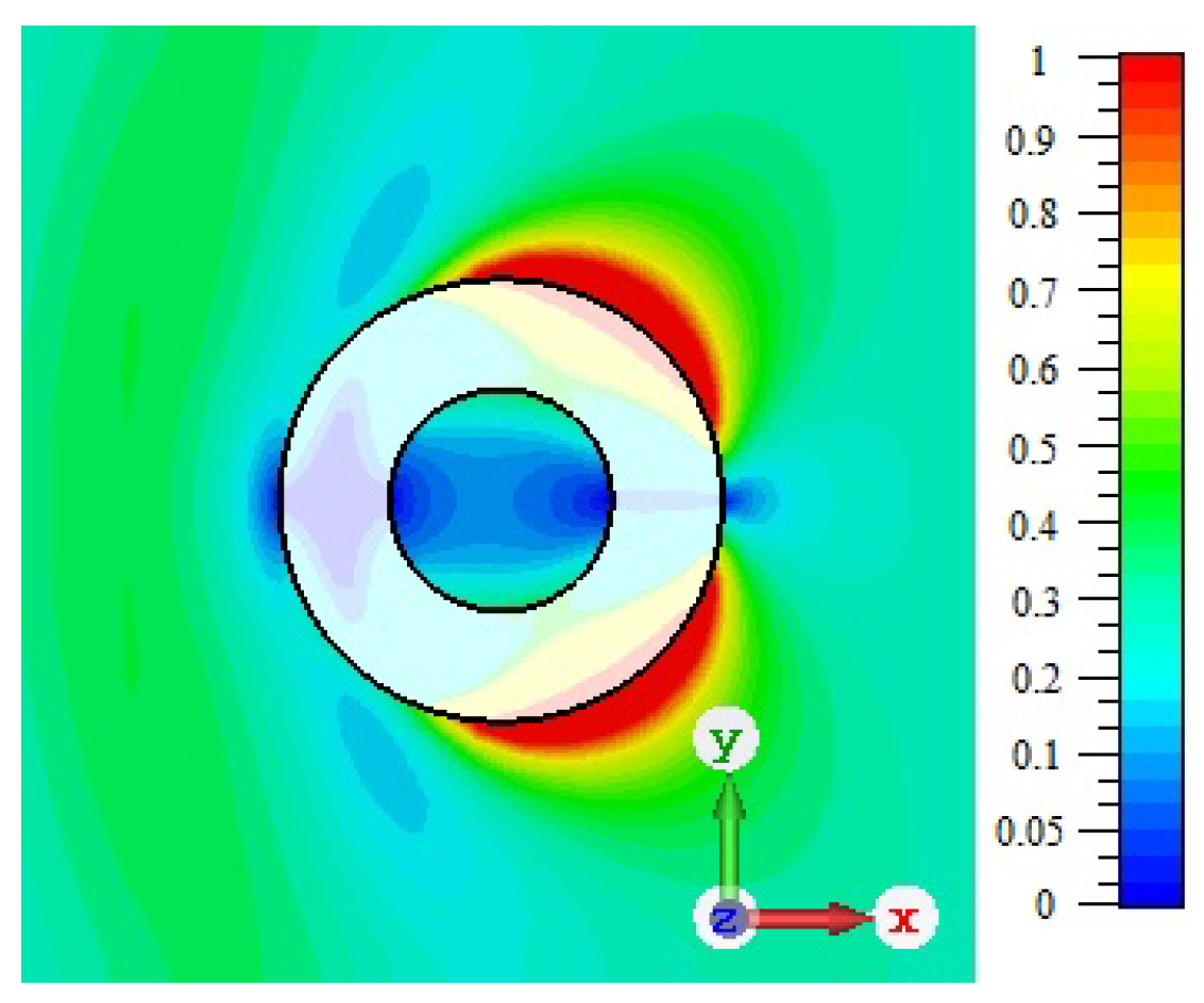
Figure 1 shows the distribution of the modulus of the electric component of the field with a wavelength of
= 119 mm, when a plane electromagnetic wave is incident perpendicular to the ring axis. In this case, the electric component intensity vector is perpendicular to the ring axis, and the magnetic intensity vector is parallel to the conductor axis.
The maximum values of the field are distributed approximately at an angle of 45° from the direction of propagation of the plane incident wave. In this case, the minimum value of the electric field is observed in the center of the hollow cylinder with an annular cross-section. The analysis of the electromagnetic field near this element allows us to choose the location of the elements when building a matrix structure. A complete analysis of the secondary field near the conductor for constructing the structure was carried out earlier in [
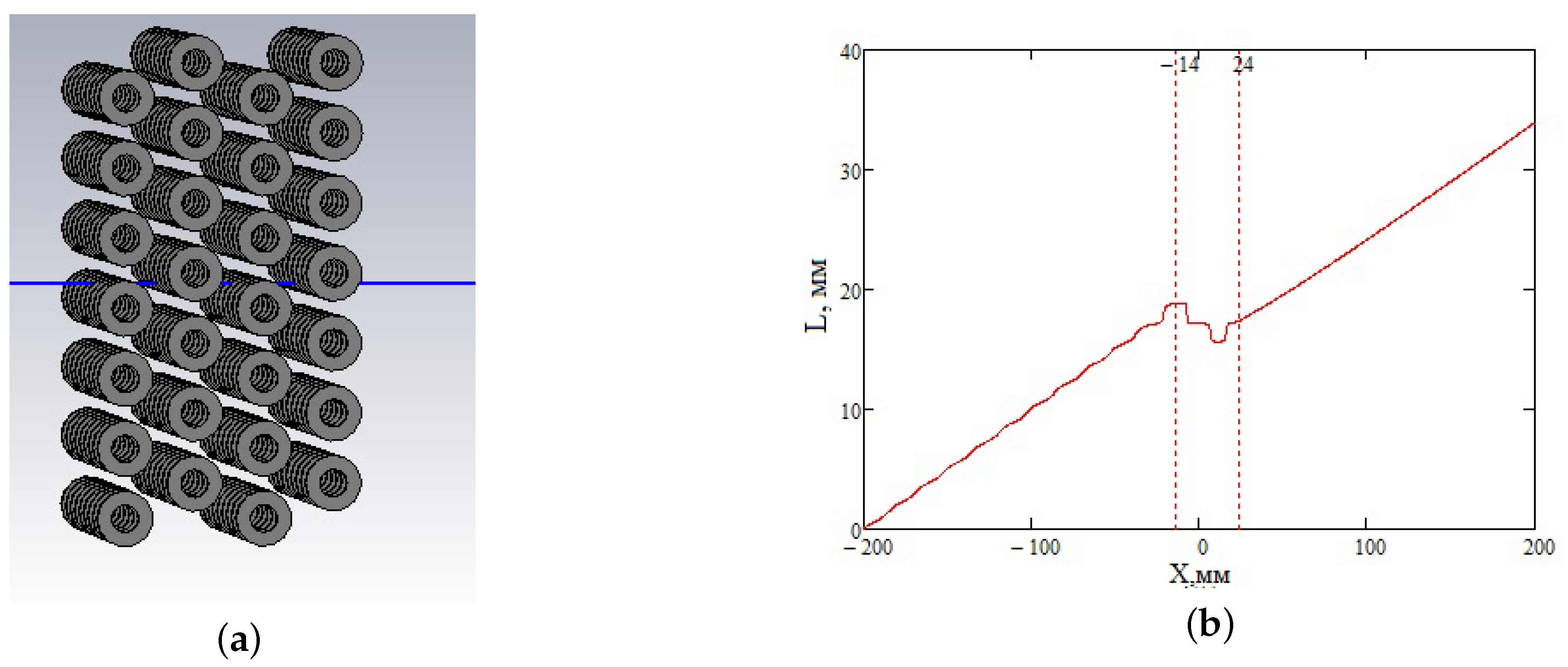
6]. The results of this study make it possible to evaluate the interaction of the ring elements with each other and achieve the greatest interaction between elements when modeling structures with a negative refractive index. When creating a composite environment, hollow cylinders with an annular cross-section must be placed line by line, making up some layers, which in turn are displaced in the transverse direction, as shown in
Figure 2a. Four elementary layers were used, so that the thickness of the full layer is h = 40 mm, and its width is b = 70 mm. In order to determine whether a given structure has the properties of a metamaterial, it is necessary to determine the phase shift along the line passing through the center of the structure. It is known that a material with a negative value of dielectric and magnetic permeability has a negative phase incursion. Therefore, it is necessary to analyze the change in the phase characteristic of the field along this line passing through the center of the model.
Figure 2b shows the dependence of the unwrapped phase, recalculated into an equivalent distance, along this straight line.
The dashed lines indicate the lattice boundaries. One can see a negative phase shift inside the layer, which indicates the occurrence of the phase front movement in the negative direction. To calculate the real part of the equivalent refractive index, we use the formula:
where
is the additional incursion of the wave path in the layer, expressed in terms of the phase incursion
, and
is the wave number. The resulting equivalent refractive index for this model is
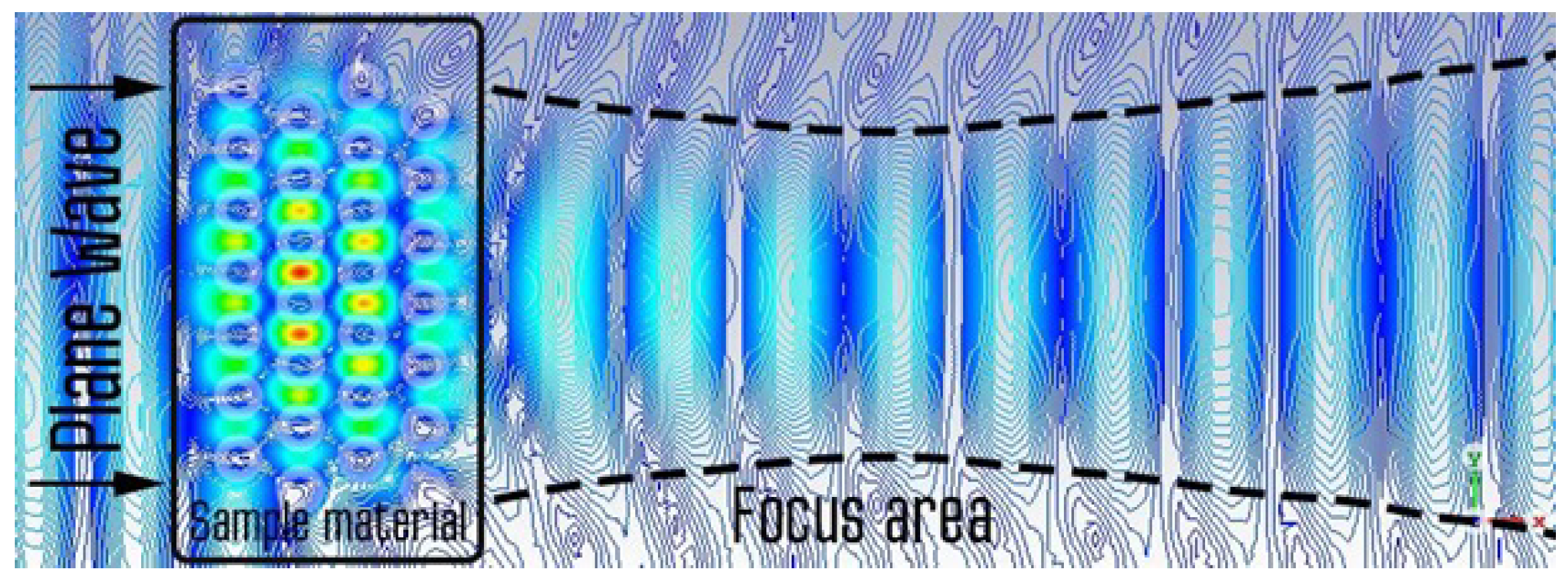
= −0.036. This means that, as a result, we have obtained a metamaterial model. The negative phase incursion at the center of the synthesized structure inevitably generates a curvature of the wave front of the resulting field at the output. To analyze this phenomenon, consider the spatial distribution of the real part of the electric field (
Figure 3).
It is clearly seen that a curvature of the phase front occurs behind the layer. This means that there is some dip in the phase shift inside the layer. It is important that the layer itself has the shape of a rectangular parallelepiped, and the negative phase incursion arises not due to any geometric curvature of the shape of the focusing system, but due to the negative refractive index inside the layer. Now, let us pay attention to the distribution of the power flow behind the constructed structure.
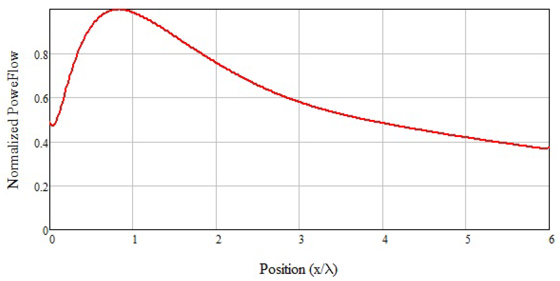
Figure 4 shows the dependence of the power flow along the longitudinal axis of the structure. The dependence is shown by the distance expressed in wavelengths. The second boundary of the constructed metamaterial layer is taken as the origin. The ordinate shows the power flux normalized to the maximum power of the transmitted wave. It can be seen that, at a distance F = 27 mm, i.e., about 0.8 of the wavelength
, a maximum power flux is observed.
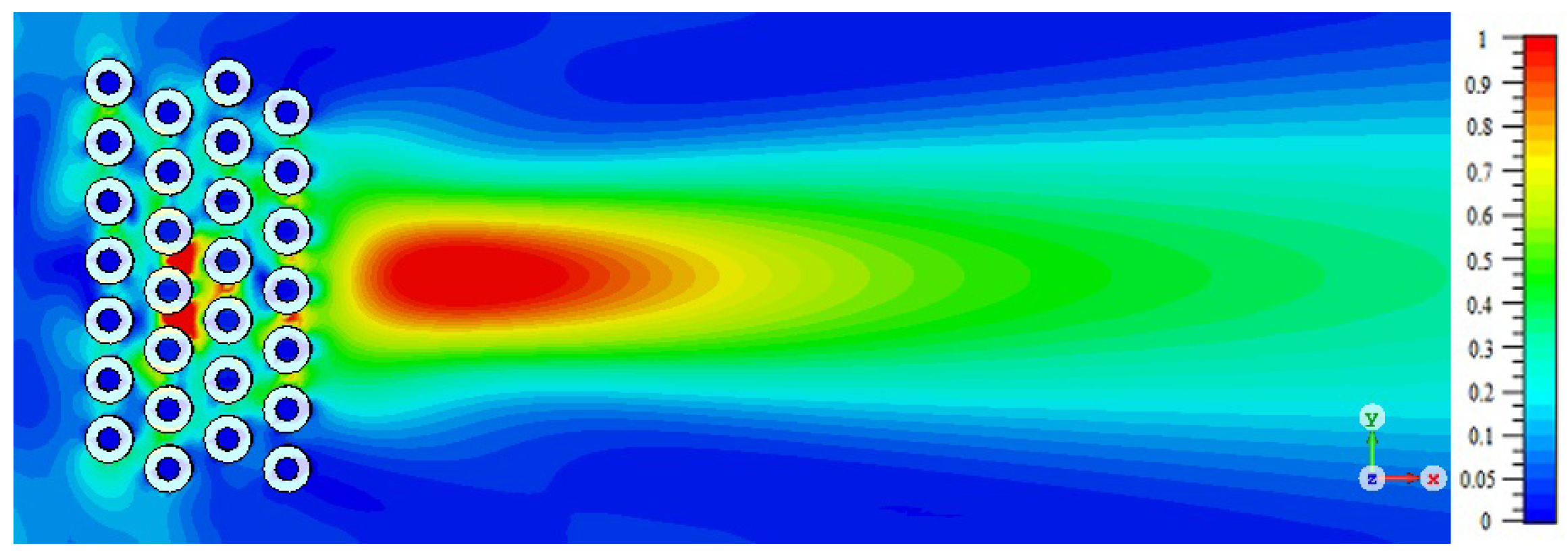
The average longitudinal distribution of the power flux in the plane of the electric field is shown in
Figure 5. It can be seen that the longitudinal localization of the focused field at the half-power level is about
= 125 mm, i.e., 3.7 of the wavelength
.
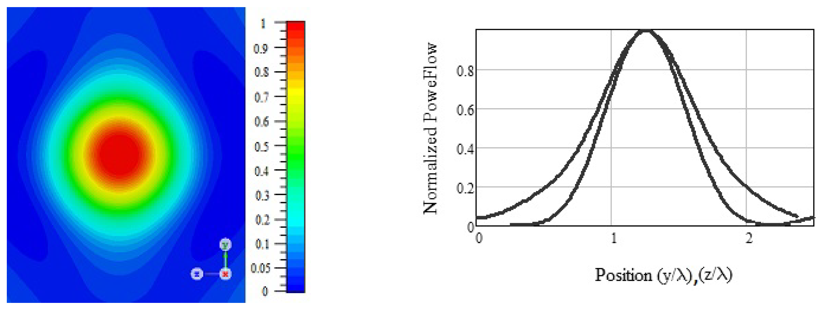
Figure 6 shows the power flow distribution in the transverse plane. It can be seen that the dimension region has an approximately elliptical cross-section with a maximum located in the center. The width of this zone according to the level of the half-power in the transverse direction is
= 27.0 mm. This corresponds to 0.8 of the wavelength
. The diffraction limit is characterized by the wavelength
, so that the resulting flat metamaterial focusing lens gives better focusing. The diffraction limit exceeded:
. The transverse size of the matrix structure of the rings is 70 mm, which is close to the size of the first Fresnel zone
D = 69 mm (2.0
) for the focal length F = 27 mm. The size of the first Fresnel zone is given by the equation:
It is important to note that conventional dielectric lenses must have a transverse dimension on which not one, but many Fresnel zones fit.
Since the ring structure of closed conductors is not sharply resonant, then, as the calculations show, the focusing properties of the synthesized matrix are preserved in a fairly wide frequency range of 1.5–3 GHz or wavelengths
= 100–199 mm.
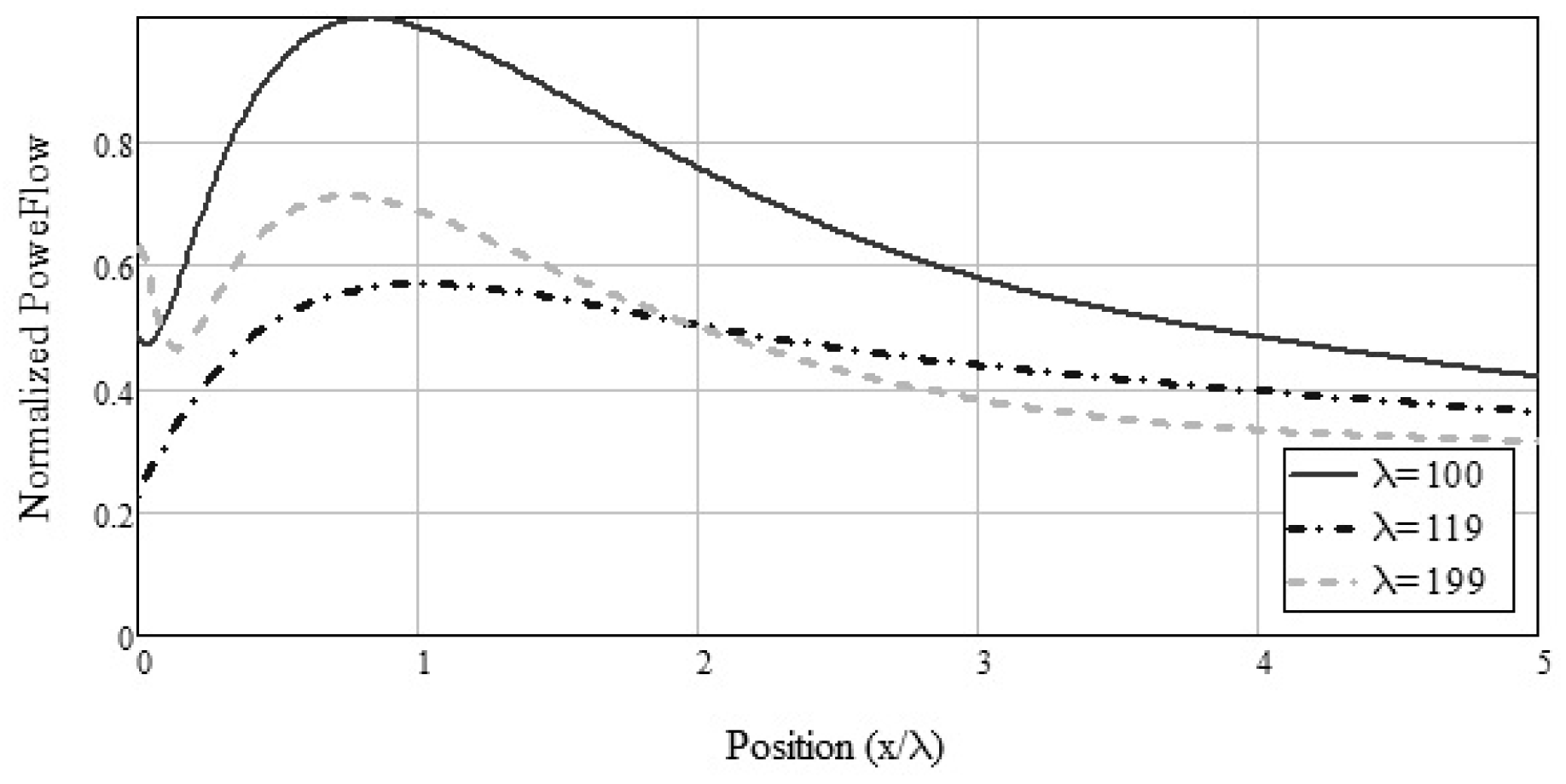
Figure 7 shows the longitudinal distribution of the focused power flux with a change in wavelength. A change in the wavelength leads to a decrease in the power of the focused radiation and to some longitudinal shift of the focus area.
The noted effect is explained by the change in the receiving size of the Fresnel zone
D from the value of the given transverse size of the synthesized structure of the metamaterial
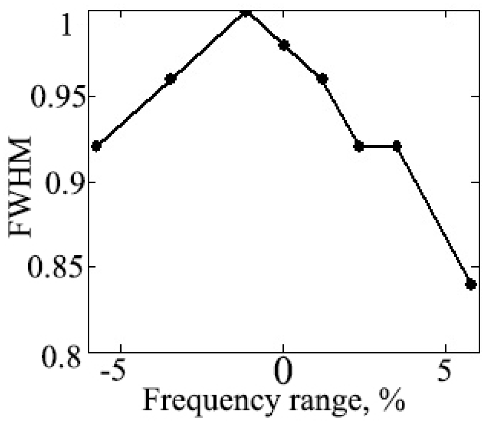
b = 70 mm. This effect leads to a change in the transverse width of the focus area (
Figure 8).
3. Experimental Study
To conduct an experimental study, a previously simulated material was made on the basis of ring elements located according to the data obtained in the simulation. The developed layout of the structure is shown in
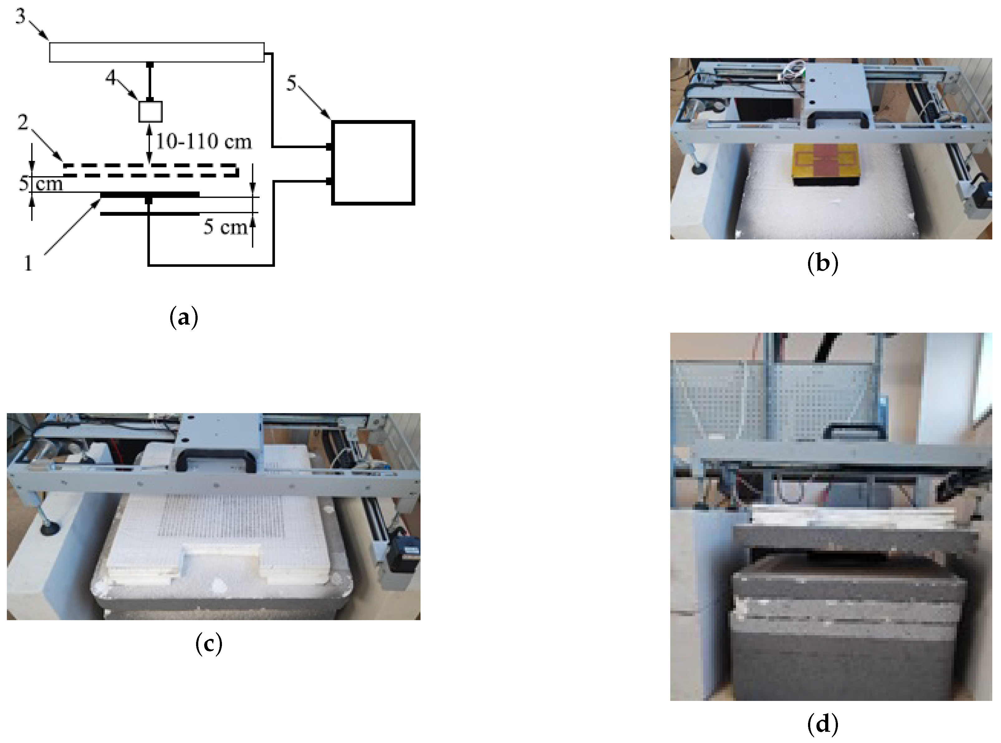
Figure 9 At the current stage, an experimental layout for one antenna was created; this approach allowed us to test the possibility of focusing. To verify the simulation, a setup was developed that allows one to see the distribution of the field at a distance from the surface of the metamaterial after radiation by the antenna from the georadar. The installation diagram is shown in
Figure 9a. The setup consisted of an antenna (1) (
Figure 9b), an experimental metamaterial sample (2) (
Figure 9c), and a two-coordinate scanner (3) with a receiving antenna (4), both antennas connected to the PNA-L NetworkAnalyzer of the Agilent Technologies company. The scanner was rearranged at different distances from the metamaterial, starting from 10 cm and, then, with a step of 20 cm, up to 110 cm.
The data were obtained in the frequency range of 0.5–3 GHz. The construction of the obtained wave projections was carried out using digital processing of the recorded amplitude–phase distribution of the field. These algorithms were used in the work. The principle of UWB data processing is based on the technology of aperture synthesis and software and hardware focusing of radiation. The method of synthesizing the aperture consists of the fact that the radar data received at each moment of sounding time are stored together with the data on the location of the receiving antenna corresponding to these time periods. The image was constructed by successively summing the received signals with the equalization of the time delays of the pulses scattered by a point with given coordinates. To do this, delays were introduced into the received signal, corresponding to the total time of signal propagation from the transmitter to the object and back. To do this, the delay time was calculated for each of the pulses. In this case, all signals registered at different points of emission–reception were summed in phase for each given point with the correction of the existing delay.
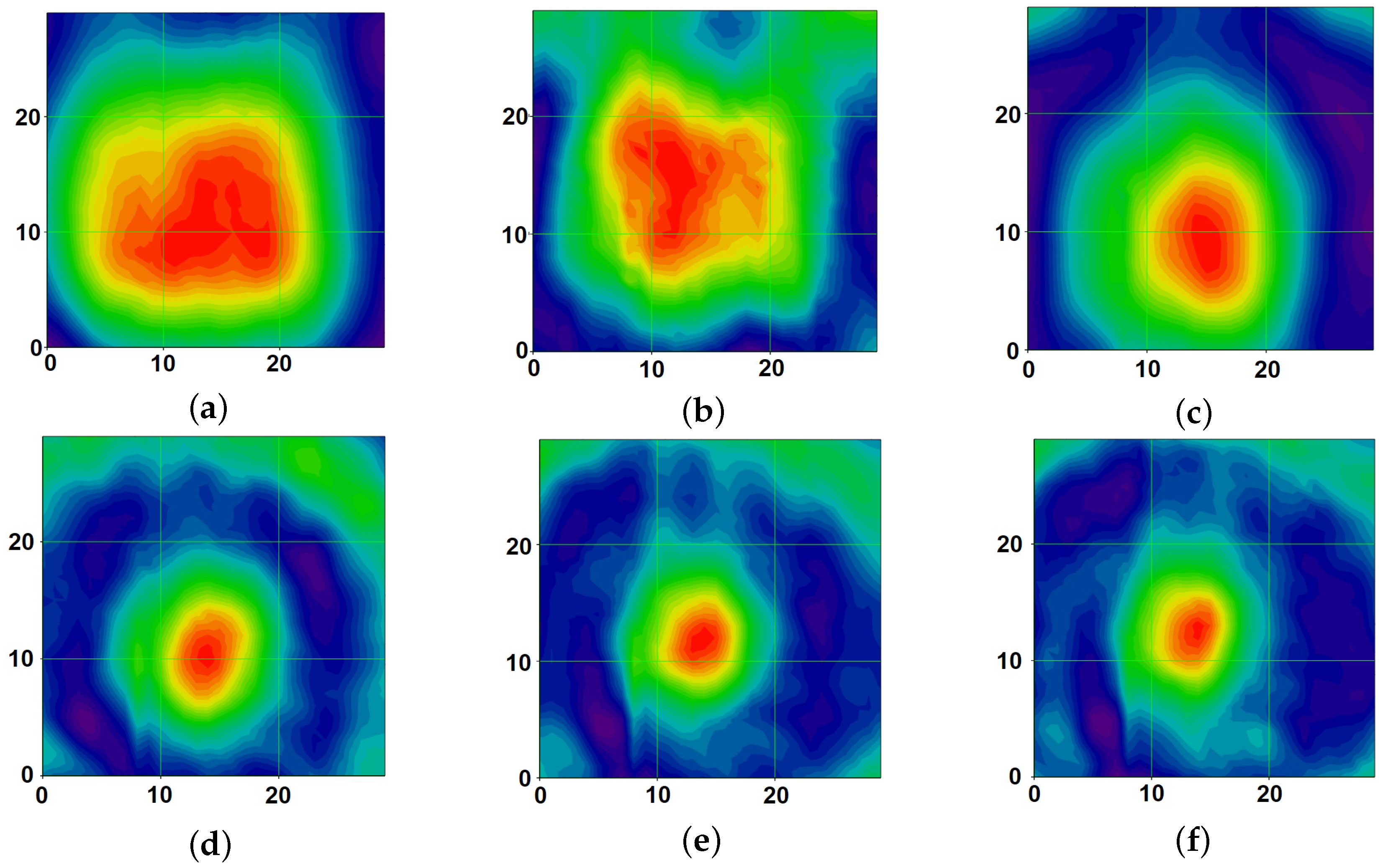
Figure 10 shows the distribution of the field amplitude over the scanning surface at different heights from the metamaterial at a frequency of 2 GHz.
It can be seen that, as the distance from the metamaterial increases, the electromagnetic field begins to gather into a beam and, at a distance of 50 cm, is focused into a spot with transverse dimensions of 12 cm and continues to decrease. Starting from a distance of 70 cm, the size of the main lobe decreases to a size of 7 cm and remains the same as the distance increases. It can also be observed that, at a small distance, the spot is rather blurred. This experiment shows the consistency of the simulation and allowed us to find the application of such a configuration in a georadar.
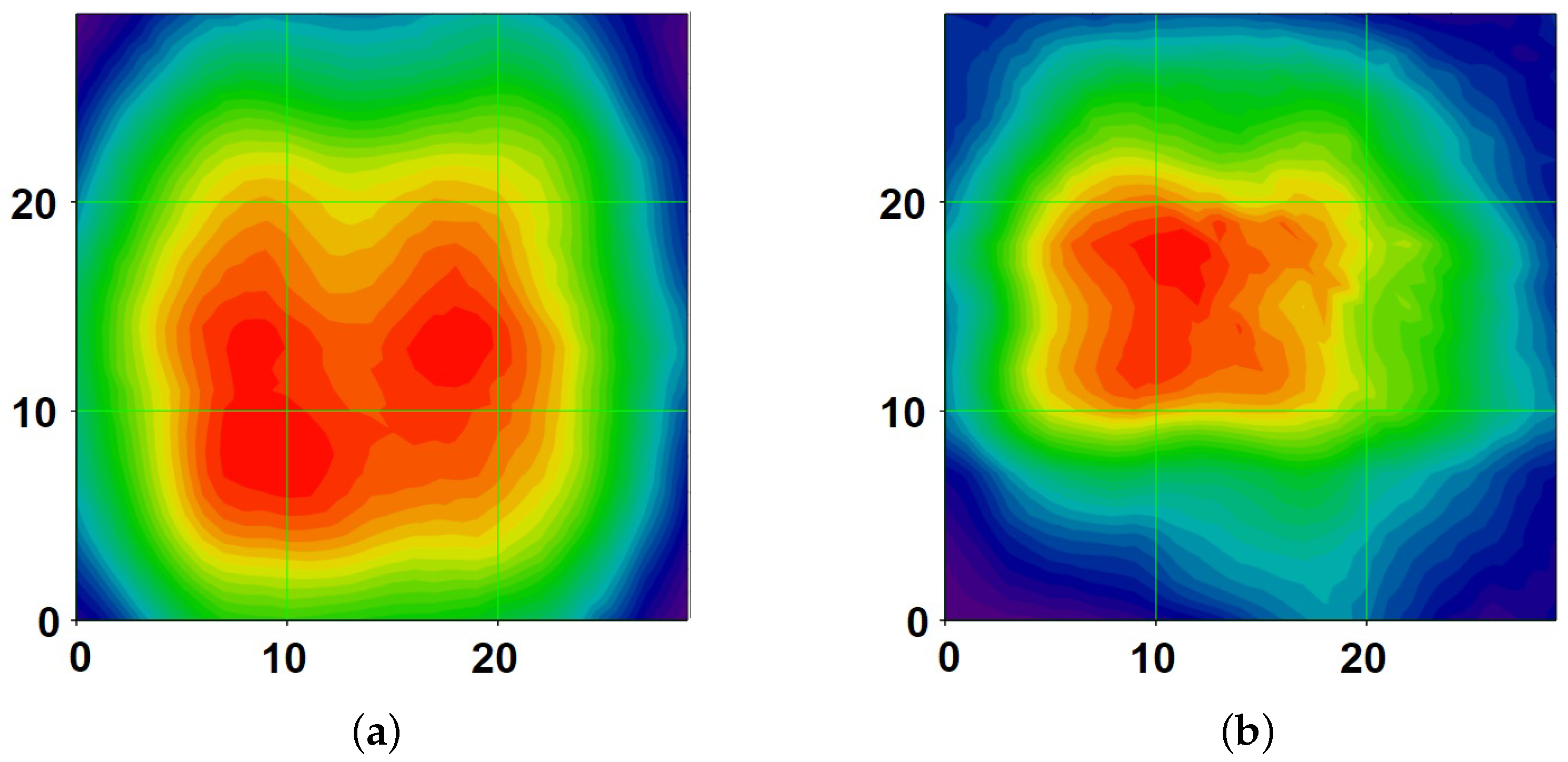
For a comparison, an experimental study of the focusing properties of the antenna without the developed metamaterial was also carried out. The resulting distributions of the electric component of the field are shown in
Figure 11.
The focusing properties were considered at a distance of 70 cm (
a) and 90 cm (
b). Such heights were chosen on the basis of an earlier experiment with a metamaterial. As can be seen from the obtained images, although the electric component of the field is narrowed by 90 cm (
Figure 11b), the resulting focusing spot is quite blurry and has dimensions of at least 17 cm. Thus, the use of the developed material makes it possible to focus the radiation from the antenna.
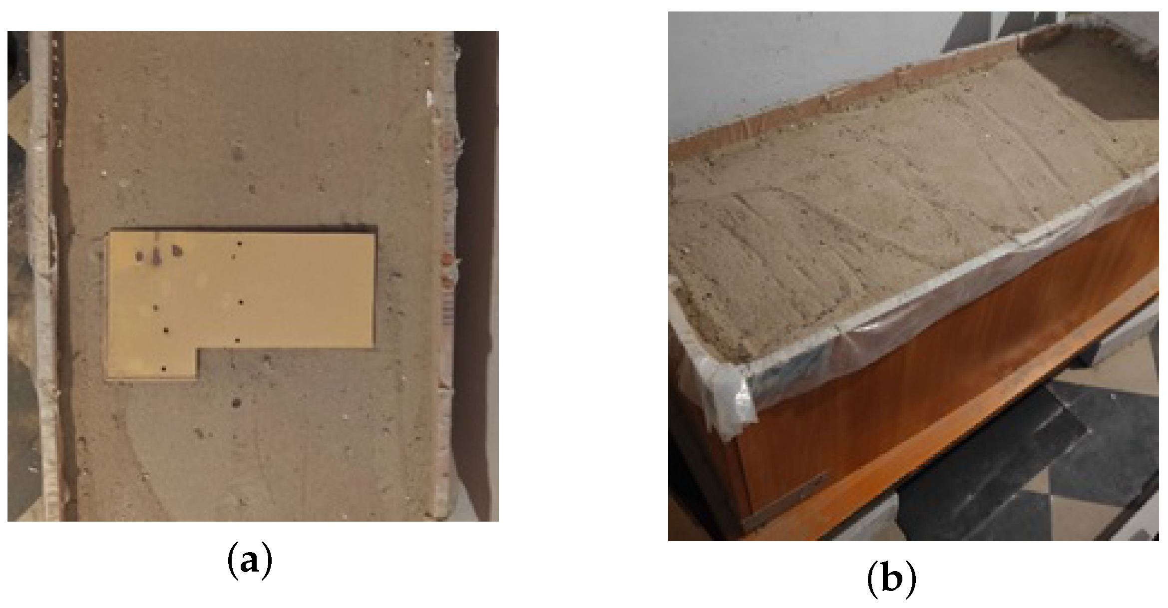
Further experimental research was based on the detection of objects in a stand with sand. The depth of the box was 50 cm. The wooden sample (
Figure 12a) was placed in a box with sand to a depth of 20 cm.
The experiment was carried out in several stages. For a comparison with the proposed system using the metamaterial, a probing system was chosen from a UWB antenna with a parabolic mirror. To create a narrow radiation pattern, the antenna was shifted from the focus of the parabolic reflector. For the convenience of the experiment, the antenna and the parabolic mirror were placed in a styrofoam cube (
Figure 13a). The measurements were carried out with a Planar CABAN R140 vector reflectometer in the frequency band of 0.5–3 GHz. To obtain a picture, scanning was carried out by moving the antennas along the stand with a step of 1 cm.
In the first stage, scanning was carried out using an antenna with a parabolic mirror (
Figure 13). The layout of the installation is also shown in
Figure 13c, where 1 is a bench with sand, 2 is a caban R140 reflectometer, 3 is a wooden sample under study, 4 is an antenna element developed by this group of authors, and 5 is a parabolic mirror. Based on the received data of the reflected signal, an oscillogram was constructed. The restored oscillogram shows that the wooden sample was found (highlighted by an oval in
Figure 13b). However, the quality of the received radio image is extremely weak against the background of signals reflected both from the upper boundary of the sand (1 in
Figure 13b) and from the lower boundary of the box (2 in
Figure 13b).
Figure 13d also shows a one-dimensional cut in the area where the wooden sample was located. The second stage of the experimental study was scanning using the fabricated system with the metamaterial. The antenna and metamaterial were placed in a 10 cm-thick foam sheet. The metamaterial was fixed at a distance of 5 cm from the antenna (
Figure 14a). Scanning was carried out in a similar way and in the same frequency band.
Figure 14b shows the reconstructed georadiogram. The object is clearly visible in it (highlighted by an oval), and the upper boundary of the air–sand interface (1 in
Figure 14b) and the lower boundary of the stand (2 in
Figure 14b) are also clearly visible. Since this image was obtained without additional mathematical processing, the boundaries of the focusing system made of the metamaterial are clearly visible (3 in
Figure 14b).
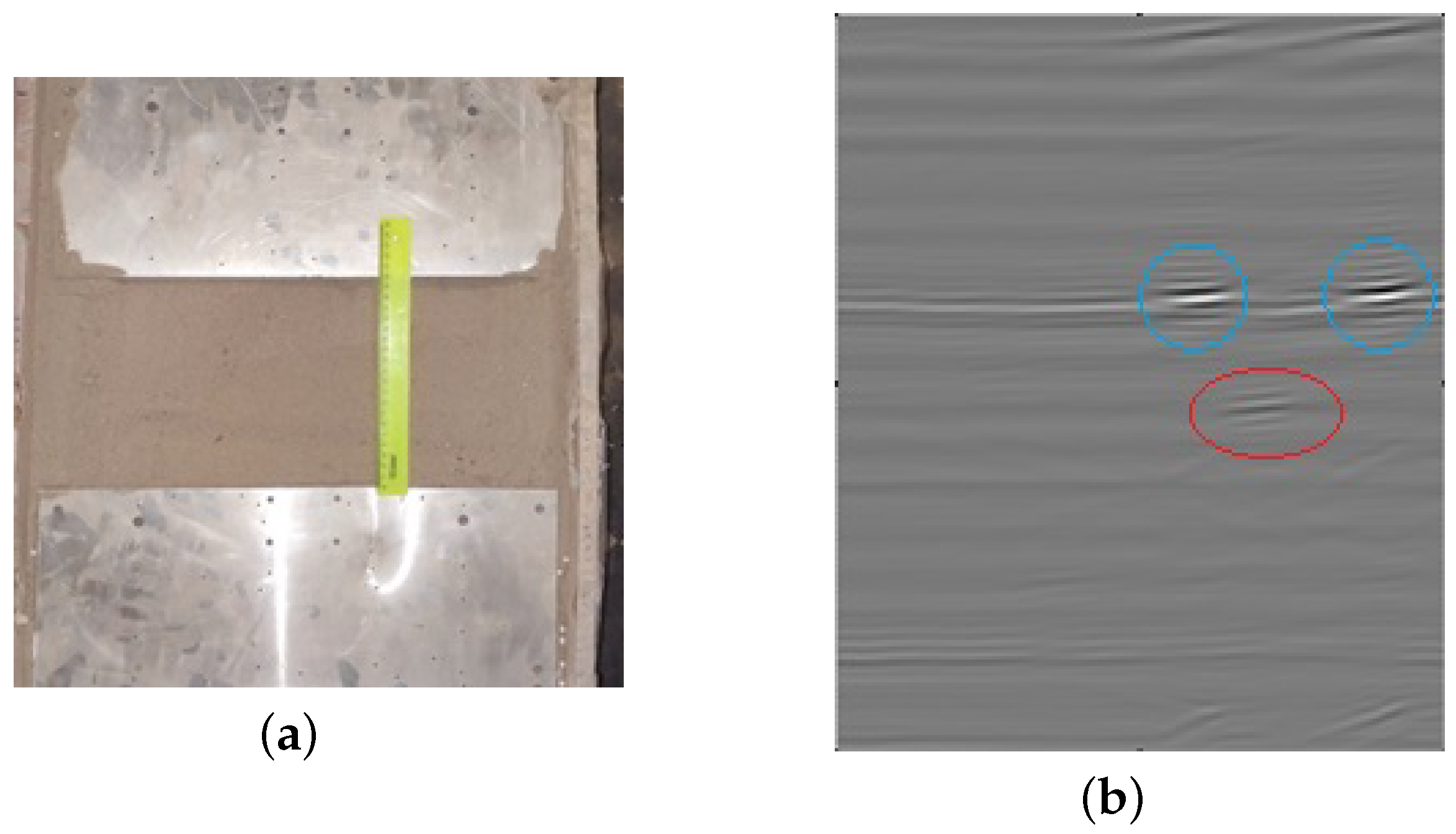
Figure 14c also shows the scheme of the installation, which includes the 1 stand with sand, 2 caban r140 reflectometer, 3 wooden sample under study, 4 antenna element developed by this group of authors, and 5 four-layer metamaterial. The antenna and the metamaterial were placed inside the foam to maintain a distance of 5 cm between them. A comparison of the images obtained in two experiments shows the advantage of the system using the metamaterial. The desired object is seen much more clearly. In the third stage of the experimental study, two metal plates were placed above the object on top of the sand at a distance of 20 cm from each other; they imitated railway sleepers (
Figure 15a).
Scanning was carried out in a similar way with a step of 1 cm and in the same frequency band of 0.5–3 GHz.
Figure 15b shows the reconstructed radiogram. In it, objects such as the metal plates (highlighted by blue circles) and the wooden object (highlighted by a red oval) were observed. Thus, the system created for geosounding shows its viability.
