Article

Seabed Terrain-Aided Navigation Algorithm Based on Combining Artificial Bee Colony and Particle Swarm Optimization

College of Intelligent Systems Science and Engineering, Harbin Engineering University, Harbin 150001, China
*
Author to whom correspondence should be addressed.
Appl. Sci. 2023, 13(2), 1166; https://doi.org/10.3390/app13021166
Submission received: 14 December 2022 / Revised: 9 January 2023 / Accepted: 13 January 2023 / Published: 15 January 2023

Abstract

:
Position errors of inertial navigation systems (INS) increase over time after long-term voyages of the autonomous underwater vehicle. Terrain-aided navigation (TAN) can effectively reduce the accumulated error of the INS. However, traditional TAN algorithms require a long positioning time and need better positioning accuracy, and nonmatching and mismatching are prone to occur, especially when the initial position error is large. To solve this problem, a new algorithm combining the artificial bee colony (ABC) and particle swarm optimization (PSO) was proposed according to the principle of terrain matching, to improve the matching effect. Considering that PSO easily falls into a local optimum, the acceleration factor and inertia weight of PSO were improved. The improved PSO was called WAPSO. ABC was introduced based on WAPSO and could help WAPSO escape local optimum. The final algorithm was termed ABC search-based WAPSO (F-WAPSO). During the continuous iteration of particles, F-WAPSO seeks the optimal position for the particles. Simulation tests show that F-WAPSO can effectively improve the matching accuracy. When the initial position error is 1000 m, the matching error can be reduced to 93.5 m, with a matching time of only 13.7 s.

1. Introduction

The autonomous underwater vehicle (AUV) has a wide application prospect in civil and military fields due to its independent and autonomous operation ability. For AUVs that undertake ultra-long distance, large depth, and all-weather submersible missions, they need to autonomously and accurately navigate in the submersible state until the task is completed. The current main underwater positioning and navigation technology of AUVs is the inertial navigation system (INS). Due to the inherent defects of accelerometer zero bias and gyro drift, position errors of the INS will accumulate with time and fail to meet the requirements of AUVs [1].
Terrain-aided navigation (TAN) helps the INS correct the position and has the advantages of autonomy, concealment, and no accumulation of error over time. First, the position sequence graph is determined using INS positions. Then, the sequence that best matches the INS position sequence graph is found on the map, and the INS is corrected to the optimal matching sequence. This is the principle in which TAN corrects the cumulative errors of the INS. The key technology of TAN is the matching algorithm [2,3]. The common matching algorithms are as follows: terrain contour matching (TERCOM), Sandia inertial TAN (SITAN), and iterative closest contour point (ICCP) [4]. SITAN uses the extended Kalman filter (KF) on the inertial terrain reference. It has good real-time performance and maneuverability but requires relatively accurate initial position error. Moreover, the algorithm is sensitive to the linearization of nonlinear observation models, and low linearization accuracy leads to filter divergence [5]. ICCP realizes position matching through repeated rigid transformation, and the matching effect is good when the initial error is small. However, when the initial error is large, mismatching will occur, and the real-time performance of ICCP is poor [6,7]. TERCOM involves correlation analysis, easily operated in practice. However, it has high computational complexity, a long output cycle, and is sensitive to course angle error [8,9].
The traditional terrain matching algorithm cannot meet the requirements for real-time navigation updates, and phenomena such as reduced positioning accuracy, algorithm instability, and long matching time are likely to occur. Terrain matching is a problem of optimization. With the development of intelligent computing, swarm intelligence optimization algorithms can be applied to INS terrain matching. Yuan et al. [10] used a chaotic search-based hybrid particle swarm optimization (PSO) to enhance the local development ability of PSO. Through the experiment, it is found that the newly proposed algorithm could effectively reduce the positioning error. Cheng et al. [11] proposed introducing PSO with convergence factors to the terrain matching of strapdown inertial navigation system (SINS) for uniform speed direct navigation experiments. The results showed that compared with TERCOM, PSO with convergence factors had higher matching accuracy and shorter matching time. However, when the initial error was large, the matching error was relatively high, which necessitated further improvement. Xin et al. [12] enhanced the performance of PSO by modifying the inertia weight and acceleration factor. The improved PSO was applied to the autonomous navigation of the unmanned surface vehicle, thus improving the stability of autonomy. PSO can be combined with other algorithms to improve its performance. Bejarbaneh et al. [13] combined PSO with the sine and cosine algorithm (SCA) and levy flight (LF), and found that the new algorithm could find global optimal solutions of different reference functions faster and improve the robustness of the system. Ji et al. [14] found a novel algorithm named SAPSO by combining PSO with simulated annealing. Although using this algorithm could improve the matching accuracy of navigation, it was time-consuming.
How to improve the matching efficiency is the key problem of the TAN system, but traditional terrain matching algorithms fail to meet the requirements of high precision and real-time. Therefore, this paper proposes a terrain matching algorithm based on PSO to improve the matching accuracy and reduce the matching time. Since PSO was proposed, it has garnered the attention of many researchers for its advantages of simple principle, fast solving speed, and strong global optimization ability. PSO has been widely used in TAN. However, due to the instability of intelligence algorithms, a single algorithm fails to meet the requirements of matching accuracy. Among these intelligence algorithms, PSO and artificial bee colony (ABC) can solve numerical optimization problems well and can be applied to terrain matching. Unlike other traditional terrain matching algorithms, PSO performs heuristic searches on the entire domain within the error range and has a stronger global searching ability. However, its diversity deteriorates in the later search period, and it can easily fall into a local optimum. By contrast, the scout bee search in ABC is a guided random search, which considers randomness, convergence, and diversity. Most importantly, it can search locally. The combination of these two algorithms can not only increase the diversity of the population but also find the optimal solution. Considering the high-precision positioning requirement of INS in a short time, this paper proposes an improved PSO search strategy based on ABC (F-WAPSO) for terrain matching. The mean Hausdorff distance (MHD) was introduced as the fitness function for terrain matching. The MHD could effectively eliminate noise and improve the stability of F-WAPSO, thus improving the matching accuracy. The optimization steps are as follows:
(1)
The traditional terrain matching algorithm has limitations on the initial position error and matching time. To this end, the matching algorithm combining ABC and PSO is proposed for INS terrain matching.
(2)
In this study, PSO is analyzed in depth, and its ability to find the global optimal solution is improved by modifying the acceleration factor c1. The improved PSO is called adaptive PSO (APSO). Meanwhile, linear decreasing inertia weights are introduced based on APSO to improve the search speed. The new algorithm is named WAPSO, and its convergence is proved.
(3)
To strengthen the particle optimization ability of WAPSO, ABC is combined with WAPSO to avoid it falling into the local optimum in later iterations, and the final algorithm is termed ABC search-based WAPSO (F-WAPSO). Subsequently, it is used for terrain matching.
(4)
The search area and fitness function are determined according to the requirements of terrain matching navigation. The algorithm’s validity is verified by experiments with real bathymetric data obtained in Weihai.

2. Principle and Model of TAN

2.1. Principle of TAN

TAN is a critical technology for the intelligent development of underwater vehicles. Its positioning error does not increase with time and thus can be combined with the INS to improve AUV positioning accuracy. According to the principle of TAN, after measuring a series of depth values on the carrier’s real-time trajectory, the depth values are input into the digital reference map for matching search. The sequence with the smallest difference from the measured terrain sequence is selected to obtain the optimal matching position of the carrier. Its real position is obtained to correct the cumulative drift error of the INS [15,16]. Figure 1 depicts the principle of TAN.
From Figure 1, it can be seen that the matching phase is the key technology of TAN. The search matching is to effectively fuse information between the real-time data of the carrier and the existing digital reference map, which directly affects the reliability of the matching results and the amount of matching calculation, significantly influencing the matching accuracy. The matching algorithm is the core of this technology, but the traditional terrain matching algorithm employs the traversal search method, which adds a significant amount of computation and severely impacts the matching time of the TAN algorithm.

2.2. State Space Model of TAN

The state space model of TAN can be described by Equations (1) and (2):
X t + 1 = X t + S t + v t
Y t = H t ( x t ) + E t
where Xt represents the indicated position coordinates of INS at time t; St represents the indicated position change between two sampling intervals of INS; vt represents the positioning error of INS; Yt represents the real-time measurement of water depth series; Ht represents the water depth series corresponding to digital reference map; and Et represents the error sequence of water depth measurement. Equation (1) can be regarded as the state equation in the TAN matching system. Equation (2) is the measurement equation. TAN finds the optimal position of inertial navigation by continuously measuring the depth of the AUV in real-time. The state equation is used to correct the errors of the INS.
Influenced by the INS course and velocity errors, the INS trajectory must be brought closer to the real trajectory during terrain matching by changing course angle and position. The transformation relationship between INS trajectory and real trajectory can be obtained through the curve affine transformation model, as shown in Equation (3). The final matching position of AUVs is obtained by constantly searching for the four optimal transformation factors k ,   β ,   δ x ,   δ y [17]:
x i u y i u = k cos β sin β sin β cos β x ^ i p y ^ i p + x 1 p y 1 p + δ x δ y
where [ x i u , y i u ] represent horizontal coordinates of the ith trajectory point; [ x ^ i p , y ^ i p ] represents the position of the ith point relative to the first trajectory point; k represents the scaling factor; β represents the course angle deviation; and δ x and δ y represent the translation factor. PSO keeps updating the parameters of the matching model, optimizes the initial trajectory to be closer to the actual trajectory, and finally obtains the optimal matching trajectory. Each particle of the optimization process represents a specific transformation on the initial trajectory, which mainly contains three attributes: position, velocity, and fitness.

3. PSO Based on ABC Search (F-WAPSO)

3.1. Improved PSO and Its Convergence Analysis

3.1.1. Improved PSO (WAPSO)

PSO is a swarm intelligence evolutionary algorithm that simulates the foraging behavior of birds. The basic idea of PSO is to abstract a bird into a “particle” without mass or volume and is equivalent to a solution to a problem. The solvable group is equivalent to a flock, and the nearest bird to the food is equivalent to the optimal solution in each generation of the solvable group. The position of the food corresponds to the global optimal solution. During the process of searching for food, birds in flight have their own flight position and velocity. Each bird can obtain the flight status information of other birds in the population and can adjust its current flight velocity and direction according to this information, so as to reach the desired position [18].
The classical particle swarm velocity update formula has three parts. The first part is the current particle velocity, which indicates the current flight state of the particle. The second part is the difference between the current position of the particle and the historical optimal position of the population, and it reflects the cooperation and knowledge-sharing among particles. The third part is the difference between the current position of the particle and its historical optimal position, indicating that the action of the particle comes from its own experience. These three parts work together to determine the searching ability of the particle. The first part endows the current particle with vigor, expands the search space, and prevents local convergence. The second part and the third part are the information exchange and cognition of the particle population respectively, and the global optimal solution is sought by constantly modifying the velocity and direction of the particle. The velocity and position update equations of PSO with inertia weights introduced by Shi and Eberhart are shown in Equations (4) and (5) [19]:
v i j ( τ + 1 ) = ω v i j ( τ ) + ϕ 1 j ( τ ) ( g b e s t j ( τ ) x i j ( τ ) ) + ϕ 2 j ( τ ) ( p b e s t i j ( τ ) x i j ( τ ) )
x i j ( τ + 1 ) = x i j ( τ ) + v i j ( τ + 1 )
where i represents the total number of particles (i = 1, 2, …, s); j represents the dimensions (j = 1, 2, …, n); ϕ 1 j ( τ ) = c 1 r 1 j ( τ ) , ϕ 2 j ( τ ) = c 2 r 2 j ( τ ) , where c1 and c2 are acceleration factors; r 1 j ( τ ) ,   r 2 j ( τ ) ( 0 , 1 ) are random numbers; ω is the inertial weight, i.e., the weight that maintains the current velocity of the particle; x i j ( τ ) is the position of particle i in the jth dimension at time τ; v i j ( τ ) is the velocity of particle i in the jth dimension at time τ; p b e s t i j ( τ ) is the individual optimal solution of particle i in the jth dimension at time τ, representing the position with the best food source passed by individual birds in their own flight, and for PSO, it is the position with the best fitness value searched by individual particles in the iterative process; and g b e s t j ( τ ) is the global optimal solution in the jth dimension at time τ, representing the position with the best food source passed by birds in the course of flight, and for PSO, it is the position with the best fitness value searched by the whole population in the iterative process.
According to Equation (4), c1 is multiplied by the difference between the position of the global historical optimal solution and the particle position, indicating the particle’s ability to approach the global optimal position. That is, c1 controls the step size of the particle flying toward the global optimal solution. If c1 is too large, the particle is more likely to fly to the current global optimal position, but it is more likely to fall into the local optimal solution while accelerating the search process. If c1 is too small, it is difficult for particles to find the global optimal solution only according to their own experience. Therefore, the c1 factor plays a key role in finding the global optimal solution for particles.
At the end of PSO iterations, the historical optimal solution of each particle gradually converges to the individual historical optimal solution, which has a slightly worse quality than the global optimal solution. In this study, the acceleration factor c1 was changed into an adaptive factor to increase the influence of the global historical optimal solution and improve the overall performance of the algorithm. The improved velocity update formula is shown in Equation (6):
v i j ( τ + 1 ) = ω v i j ( τ ) + c 1 ( τ ) r 1 g b e s t j ( τ ) x i j ( τ ) + c 2 r 2 p b e s t i j ( τ ) x i j ( τ )
where c 1 ( τ ) = 2 × t h τ × c 1 = 2 × e τ e τ e τ + e τ × c 1 and c1 becomes a hyperbolic tangent time-varying function. With an increasing number of iterations, c1 becomes larger, making the probability of the particle approaching the global historical optimal solution increase in later iterations. The improved PSO is termed adaptive PSO (APSO).
Dynamic ω can improve the optimization speed and make the population find the global optimal solution more quickly. In this study, the linear decreasing inertia weight is introduced as shown in Equation (7). The inertia weights decrease linearly. At the beginning of iterations, large inertia weights are used to accelerate the convergence speed. At the end of iterations, small inertia weights are used to improve the search accuracy:
w ( τ ) = w min + ( w max w min ) × τ max τ τ max
where τ max is the maximum number of iterations, ω min and ω max are the minimum and maximum inertia factors, respectively. Typically, ω min = 0.4 and ω max = 0.9 [20]. The APSO with linear decreasing inertia weights is named WAPSO, Table 1 depicts the calculation steps of WAPSO.

3.1.2. Convergence Analysis of WAPSO

Theorem 1.
Each particle converges to a stable point pi, where p i = ϕ 1 p b e s t + ϕ 2 g b e s t ϕ 1 + ϕ 2 , lim t + x i ( τ ) = p i .
Proof of Theorem 1.
The velocity and position update formulas are as follows:
v ( τ + 1 ) = ω v ( τ ) + ϕ 1 ( p b e s t x ( τ ) ) + ϕ 2 ( g b e s t x ( τ ) )
x ( τ + 1 ) = x ( τ ) + v ( τ + 1 )
Substituting Equation (8) into Equation (9) gives Equation (10):
x τ + 1 = ( 1 + ω ϕ 1 ϕ 2 ) x τ ω x τ 1 + ϕ 1 p b e s t + ϕ 2 g b e s t
Equation (10) can be converted to:
x τ + 1 x τ 1 = 1 + ω ϕ 1 ϕ 2 ω ϕ 1 p b e s t + ϕ 2 g b e s t 1 0 0 0 0 1 x τ x τ 1 1
The characteristic polynomial of Equation (11) is as follows:
1 λ λ 2 λ 1 + ω ϕ 1 ϕ 2 + ω = 0 .
The characteristic solution can be written as follows:
λ 1 = 1 + ω ϕ 1 ϕ 2 + ε 2 ,
λ 2 = 1 + ω ϕ 1 ϕ 2 ε 2 ,
where ε = 1 + ω ϕ 1 ϕ 2 2 4 ω .
Under initial conditions x 0 = x ( 0 ) and x 1 = x ( 1 ) , the recurrence relation is:
x τ = k 1 + k 2 λ 1 τ + k 3 λ 2 τ
where k 1 = ϕ 1 p b e s t + ϕ 2 g b e s t ϕ 1 + ϕ 2 ,   k 2 = λ 2 x 0 x 1 x 1 + x 2 ε λ 1 1 ,   k 3 = λ 1 x 1 x 0 + x 1 x 2 ε λ 2 1 .
The convergence of the particle can be expressed as follows:
lim τ + x τ = k 1 = ϕ 1 p b e s t + ϕ 2 g b e s t ϕ 1 + ϕ 2
For any complex number z, z τ can be written as follows:
z τ = z e l θ τ
z τ = z τ cos θ τ + l sin θ τ
where θ = arg z . Then, the convergence is expressed as follows:
lim τ + z τ = lim τ + z τ cos θ τ + l sin θ τ
When z < 1 , then lim τ + z τ = 0 , λ 1 > 1 or λ 2 > 1 , the system diverges, and lim τ + ( k 1 + k 2 λ 1 τ + k 3 λ 2 τ ) does not exist.
When z = 1 , lim τ + z τ = lim τ + 1 τ cos θ τ + l sin θ τ does not exist, and λ 1 = 1 or λ 2 = 1 , and the system diverges.
When λ 1 < 1 and λ 2 < 1 , the system diverges. Because λ 1 < 1 , lim τ + λ 1 τ = 0 and because λ 2 < 1 , lim τ + λ 2 τ = 0 ; then, lim τ + x τ = k 1 = ϕ 1 p b e s t + ϕ 2 g b e s t ϕ 1 + ϕ 2 .
This satisfies the proof. □
Conclusion: When λ 1 < 1 and λ 2 < 1 , the particle or particles swarm converges to a weighted average of its individual and global optimal positions. The convergence point is p i = ϕ 1 p b e s t + ϕ 2 g b e s t ϕ 1 + ϕ 2 .

3.2. WAPSO Based on ABC

WAPSO improves the ability of searching global optimal solutions and accelerates the search speed. However, at the end of iterations, the randomness of the algorithm will be weakened and it will fall into the local optimum due to the increase of its dependence on the global optimal solution. To strengthen the optimization ability of the algorithm, ABC was introduced to search WAPSO and enhance its development ability.
ABC deals with the function optimization problem by simulating the actual honey collecting mechanism of bees. It regards the nectar source as a feasible solution in the solution space of the optimization problem. The position of the nectar source represents the value of the feasible solution, and its concentration represents the quality of the feasible solution. The higher the concentration of the nectar source, the better the quality of the feasible solution. ABC keeps the good feasible solution and eliminates the bad feasible solution in the continuous iterative calculation, and gradually approaches the global optimal solution in the solution space. In a standard ABC, there are three types of individual bees: the employed forager, onlooker bee, and scout bee. Scout bees do a random global search at the beginning. Employed foragers guide the colony in the optimal direction and transmit nectar source information to onlooker bees. Onlooker bees compare the information provided by multiple employed foragers and choose the place with the highest nectar concentration, so as to jump out of the local optimum [21,22]. The operation flow of ABC follows.
First step: initialization. Each scout bee randomly selects a position in the solution space. At the beginning of the problem-solving process, half of the artificial bees in the population will be initialized as scout bees in the solution space. The detailed formula is expressed in Equation (15):
x i j = x j L + r × x j U x j L
where x i j represents the ith initial solution in the jth dimension; x j L and x j U stand for the lower and upper bounds of the jth dimension, respectively, and r (0, 1) is a random number.
Second step: search phase of employed foragers. The employed foragers search for a new nectar source around the one that they have found and select a nectar source with a higher concentration than the old one. The specific calculation formula is shown in Equation (16):
x i j ( τ + 1 ) = x i j ( τ ) + 2 r 1 × r a n g j
where x i j ( τ ) and x i j ( τ + 1 ) represent the solution of the ith employed forager at time τ and τ + 1 in the jth dimension; rangj is the search range of the jth dimension.
Third step: search phase of onlooker bees. The higher the nectar concentration, the more likely is the source to be selected by onlooker bees. The probability density formula is shown in Equation (17):
p i = f i t i i = 1 N / 2 f i t i
where pi is the probability that the ith nectar source is selected by onlooker bees, N is the population size, and fiti is the fitness of the ith nectar source.
WAPSO particles in the hybrid algorithm are regarded as employed foragers in ABC, and onlooker bees conduct a greedy search around them. Onlooker bees are set to search around each particle as shown in Equation (18):
r a n g j = x j U x j L 10 , j = 1 ,   2 ,   ,   D
where x j L and x j U represent the lower and upper bounds of the decision variable, respectively, in the jth dimension, and D represents the dimension [23,24].
In the continuous searching process of ABC, particles always develop toward a better fitness function value, and the original solution is replaced only when a better solution is found. The hybrid algorithm first conducts a WAPSO search, then introduces ABC search and the particle with the best fitness function value is selected as the global optimal solution. Such a search strategy differentiates ABC from other swarm intelligence optimization algorithms, and it is a guided random search. ABC greatly improves WAPSO’s tendency to fall into the local optimum in later iterations. In this study, WAPSO based on ABC search is termed F-WAPSO, whose pseudocode is listed in Table 2.

4. Terrain Matching Search Strategy Based on the F-WAPSO

4.1. Search Area

In the process of TAN matching, the search area is determined according to the current position of INS. If the search area is too small, the real position of the carrier will be missed, which will almost certainly result in a matching failure. If the search area is too large, the calculation amount will increase and the matching speed will suffer. In this paper, the size of the search area is determined according to the position error ellipse in inertial navigation. It is assumed that the inertial navigation position error follows the standard normal distribution, where σ x and σ y are the east and north standard deviations of INS location system, respectively, and σ x 2 , σ y 2 , σ x y , and σ y x are the variances and covariances of the positioning system. Hence, the INS error ellipse calculation formula can be written as shown in Equation (19):
a = σ ^ 0 1 2 ( σ x 2 + σ y 2 + ( σ x 2 σ y 2 ) 2 + 4 σ x y 2 ) b = σ ^ 0 1 2 ( σ x 2 + σ y 2 ( σ x 2 σ y 2 ) 2 + 4 σ x y 2 ) φ = π 2 1 2 arctan ( 2 σ x y / ( σ x 2 σ y 2 ) )
where a and b are the major and minor axes of the ellipse, respectively; φ is the angle between the major axis of the ellipse and due north; and σ ^ 0 is the expansion factor. For the convenience of calculation, an enclosing rectangle of the error ellipse is used, and its formula is shown in Equation (20):
x m = 2 a 2 sin 2 φ + b 2 cos 2 φ y m = 2 a 2 cos 2 φ + b 2 sin 2 φ
where xm and ym are the length and width of the enclosing rectangle, respectively. According to the “3 σ ” principle, when σ ^ 0 = 3.03, the confidence degree of the error ellipse can reach 95%. Considering various uncertainty errors in practical application, σ ^ 0 = 4 was used in the simulation experiment of this paper.

4.2. Search Strategy

The selection of the fitness value function directly affects the solution quality of F-WAPSO. The MHD has a strong anti-interference ability and reduces the influence of noise. Using the MHD as the fitness function can improve terrain matching [25].
The true value of the bathymetric measurement sequence is C = {c1, c2, …, cL}, ci = (cxi, cyi, czi), which is the value of longitude, latitude, and water depth of the measuring point. The L in i = 1, 2, …, L is the length of the measurement sequence. Since the horizontal coordinates and water depth of each point on the topographic map can be mapped by digital maps, the corresponding real-time water depth sequence of C on the chart is:
MC = {mc1, mc2, …, mcL}, mci = (mcxi, mcyi) are the horizontal position coordinates.
Using the position indicated by INS as the center, the bathymetric sequence C was used as the template to find the matching sequence Pj within the search area. The matching water depth sequence is: Pj = {p1j, p2j, …, pLj}, pij = (pxij, pyij, pzij) (i = 1, 2, …, L; j = 1, 2, …, xm × ym), and the corresponding horizontal position coordinate sequence is:
MPj = {mp1j, mp2j, , mpLj}, mpij = (mpxij, mpyij). As a fitness function, the MHD is defined as:
D M H D ( M C ,   M P j ) = 1 L i = 1 L min m p i j M P j m c i m p i j
where . is a distance norm, and DMHD represents the directed MHD distance between two point sets. The smaller the distance, the better the degree of matching.
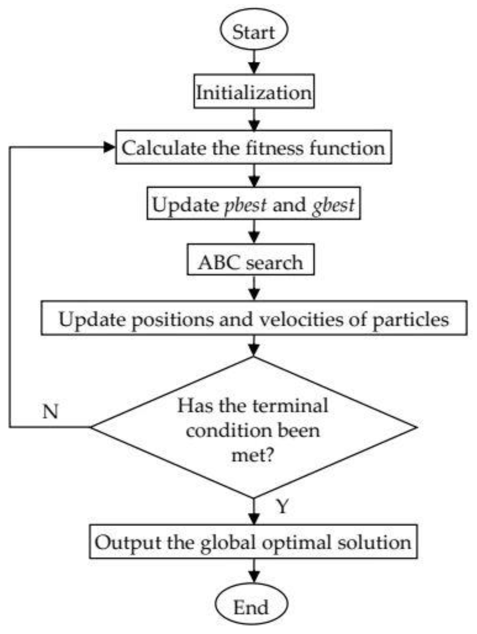
Figure 2 depicts the flow chart of the terrain matching algorithm based on F-WAPSO.
The main steps of the terrain matching algorithm based on F-WAPSO could be described as follows:
1.
Initialization. Set F-WAPSO parameters and select a population of particles in search space with random positions and velocities.
2.
Calculate each particle’s fitness function value. After the optimization target has been established, that is, the matching sequence of the starting point node represented by the current particle, the search range is determined by Equations (19) and (20). The optimal matching sequence is determined by the minimum MHD sequence between the searched and measured terrain elevation sequences according to this range.
3.
Update the individual optimal solution and the global optimal solution. First, each particle’s current fitness value is compared with the individual optimal solution pbest. If the current fitness value is less than pbest, pbest is updated as the current fitness value of the particle. Second, the current fitness value of each particle is compared with the global optimal solution gbest. If the current fitness value is less than gbest, gbest is updated as the current fitness value of the particle.
4.
ABC conduces greedy search. During the ABC search, particles in the hybrid algorithm are taken as the employed forager, and onlooker bees make greedy searches around it.
5.
Update the individual optimal solution and global optimal solution. In the ABC search, the MHD is also selected as the fitness function, and the minimum MHD corresponds to the optimal matching sequence.
6.
Determine whether the terminal condition has been met. The termination condition is that the maximum number of iterations has been reached or the global optimal sequence and the measured topographic elevation sequence have reached the minimum value.
7.
If the termination condition has been met, output the optimal matching sequence and its corresponding position. Otherwise, return to step 2.

5. Simulation and Analysis

5.1. Settings of Simulation Parameters

The seabed depth data used in this study were obtained from Weihai, which is located in 122.0568° E–122.1263° E and 35.5704° N–37.6078° N. Data were collected by using a multi-beam sounding system, which could continuously collect 256 depth values at one time. The interpolation has 1391 × 750 grid points. Figure 3 shows the two-dimensional and three-dimensional isobath graphs of the sea area, respectively.
In this study, the results shown in Figure 3 were obtained by simulation in MATLAB software. The observation error of the multi-beam sounder was 3 m. The gyroscopic drift of the INS was 0.01°/h, and the constant bias of the accelerometer was 0.01 mg. Each matched trajectory was spaced 1 s and contained 14 sampling points.
F-WAPSO parameter setting: The number of particles was 100, and the maximum number of iterations was 100. The acceleration factor c1 at [0, 2] gradually increased with the number of iterations, and the acceleration factor c2 = 1.35. The inertia weight ω decreased linearly at [0.4, 0.9], and the number of colonies was set to 100. By setting different initial position errors as the position errors that INS has accumulated when the underwater vehicle enters the matching area, the matching effects of TERCOM and F-WAPSO matching algorithm were compared. To ensure data consistency, the average of 30 runs of the algorithm was obtained.

5.2. Results of Simulation

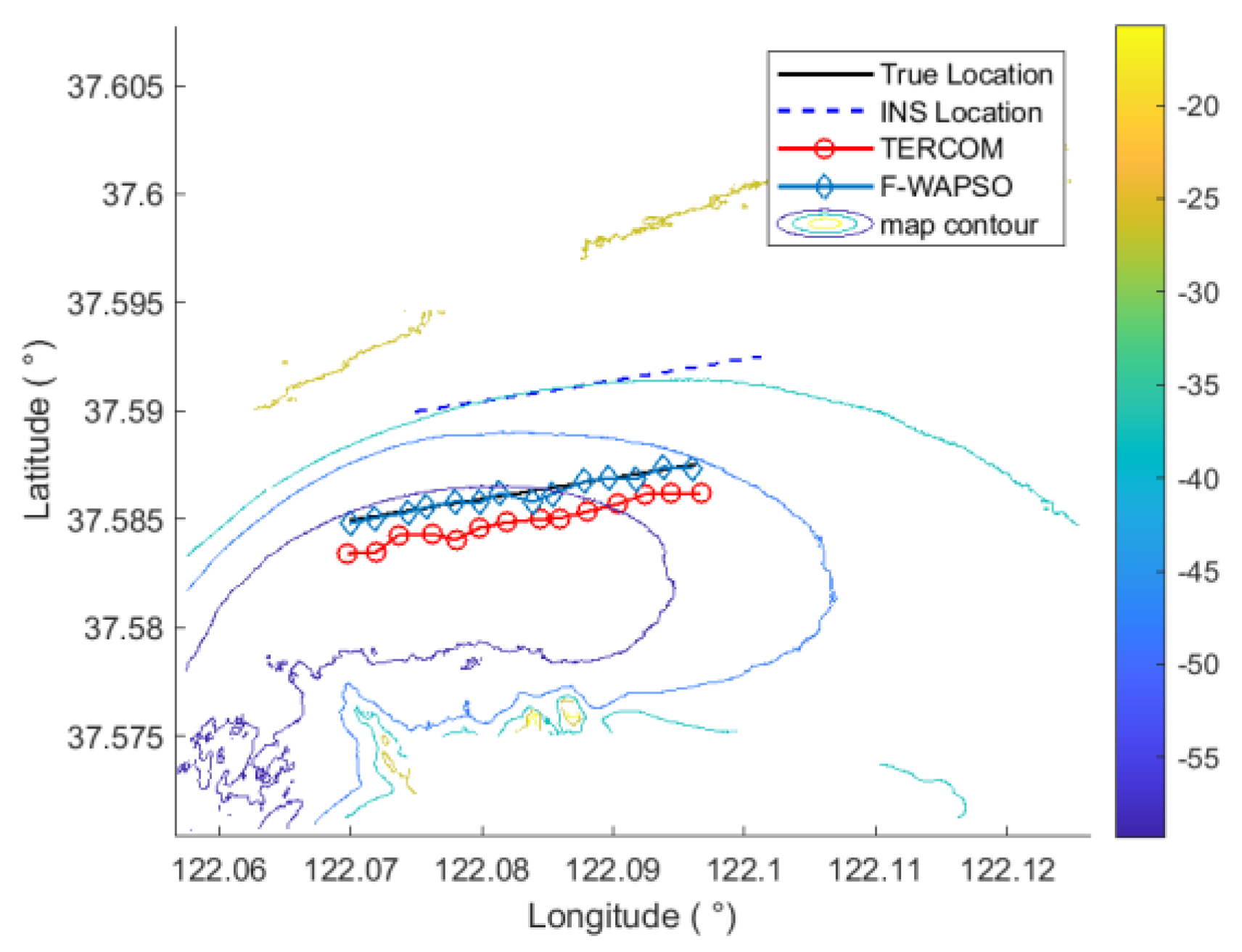
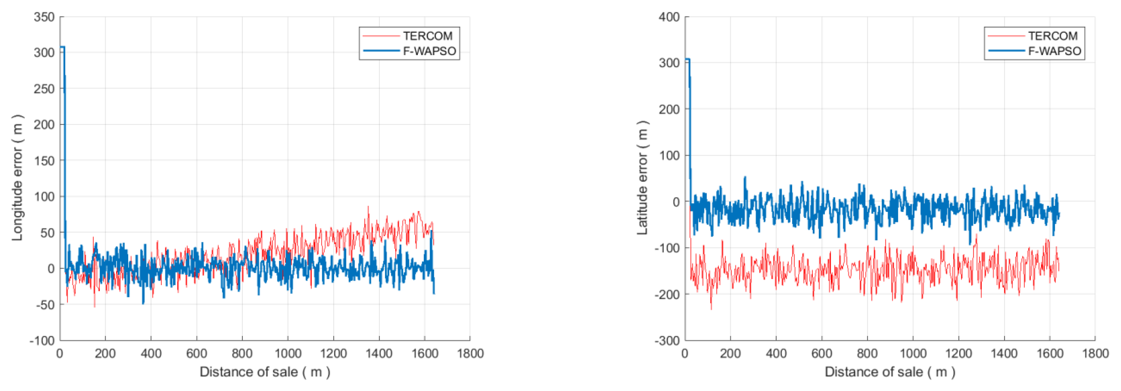
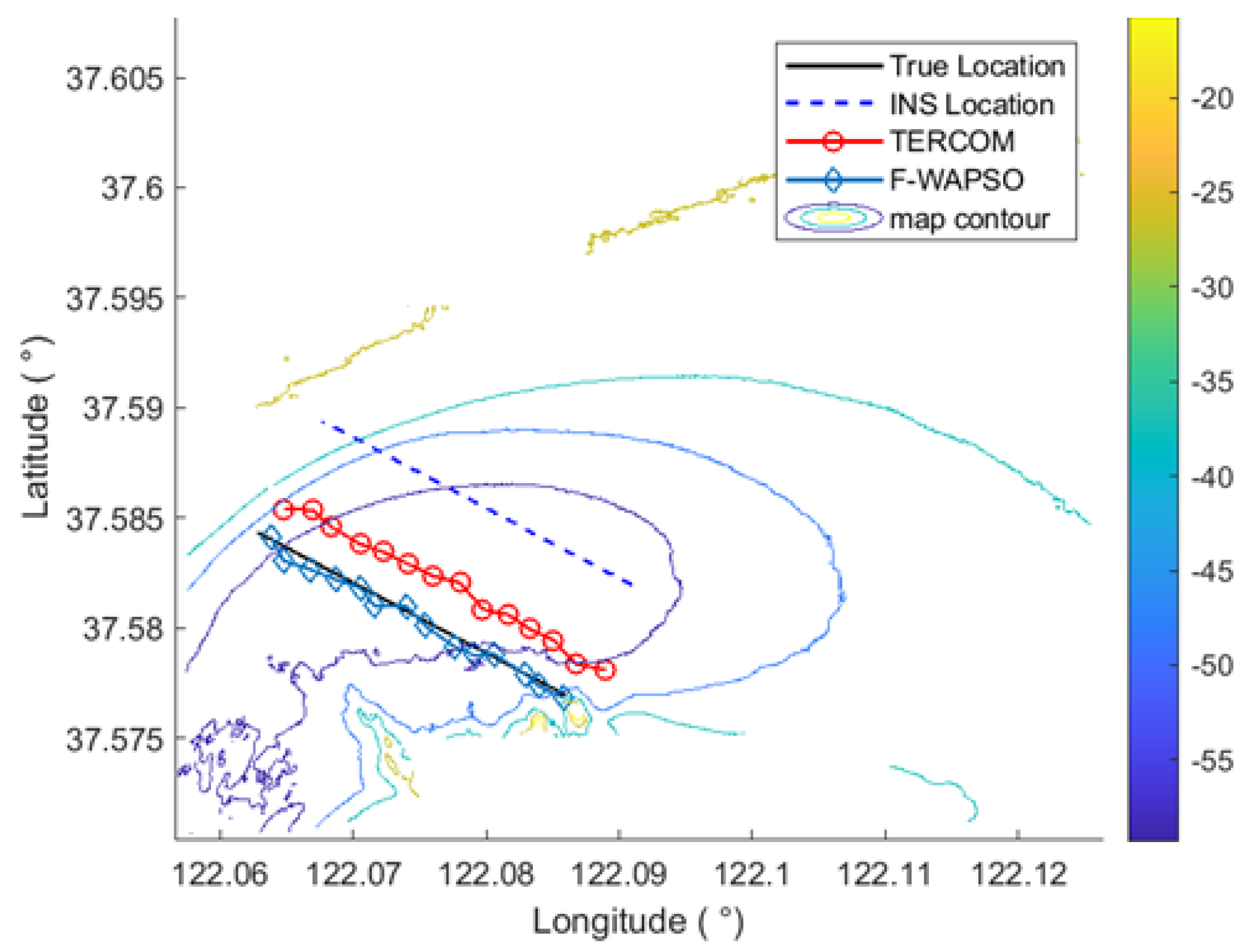
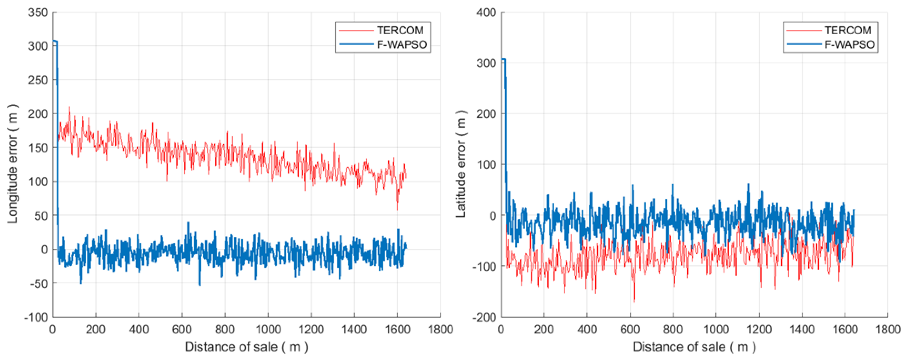
Trajectory A: the initial position of the underwater vehicle was 122.07° E, 37.585° N. The initial location of INS was 300 m to the east, and 300 m to the north; the initial course was 10° north by east, and the vehicle traveled straight at a constant speed. Figure 4 shows the trajectories of the two matching algorithms. Figure 5 shows the longitude and latitude error curves of trajectory A.
In Figure 4, the matching accuracy of F-WAPSO is significantly better than that of TERCOM. In Figure 5, in the longitude error curve, the error of TERCOM oscillates around 0 m in the early stage and gradually increases in the late stage, whereas that of F-WAPSO oscillates consistently around 0 m. In the latitude error curve, the error of TERCOM is between −100 and −200 m, and that of F-WAPSO is between −100 and 50 m. Table 3 lists the statistical results of trajectory A. The matching error is expressed by the mean value of the root mean square of the longitude and latitude errors of the whole orbit sequence.
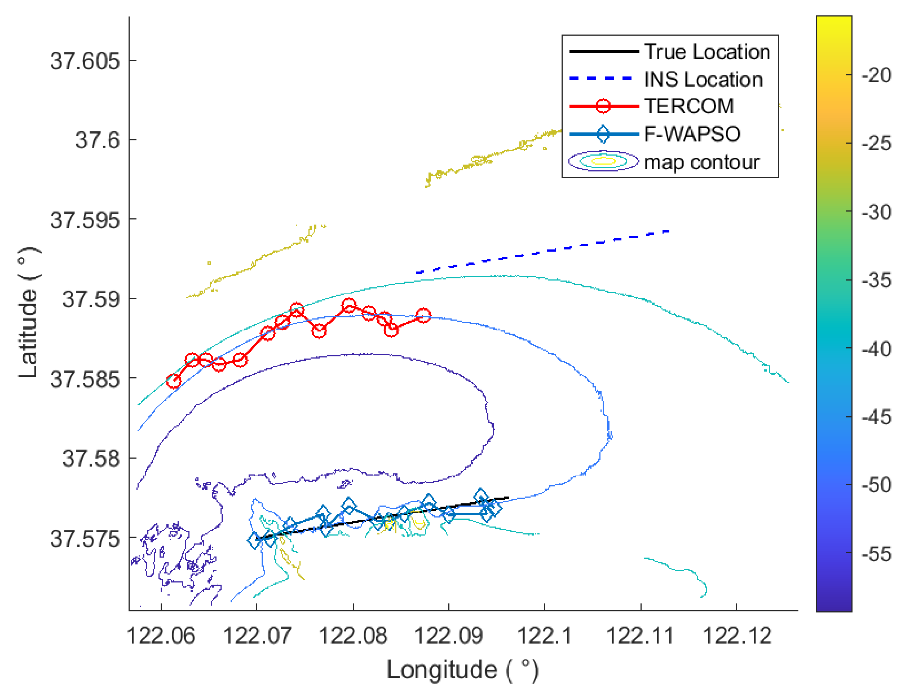
Trajectory B: The initial location of the underwater vehicle was 122.07° E, 37.575° N. The initial location of INS was 1000 m to the east, and 1000 m to the north; and the initial course is 10° north by east, and the vehicle traveled straight at a constant speed. Figure 6 shows the trajectories of the two matching algorithms. Figure 7 shows the longitude and latitude error curves of trajectory B.
In Figure 6, F-WAPSO has remarkably better matching accuracy than TERCOM. In Figure 7, the longitude error of TERCOM is between 0 and 300 m, whereas that of F-WAPSO is between −100 and 100 m. Furthermore, the latitude error of TERCOM is between 0 and 400 m, whereas that of F-WAPSO is between −200 and 200 m. Table 4 lists the statistical results of trajectory B.
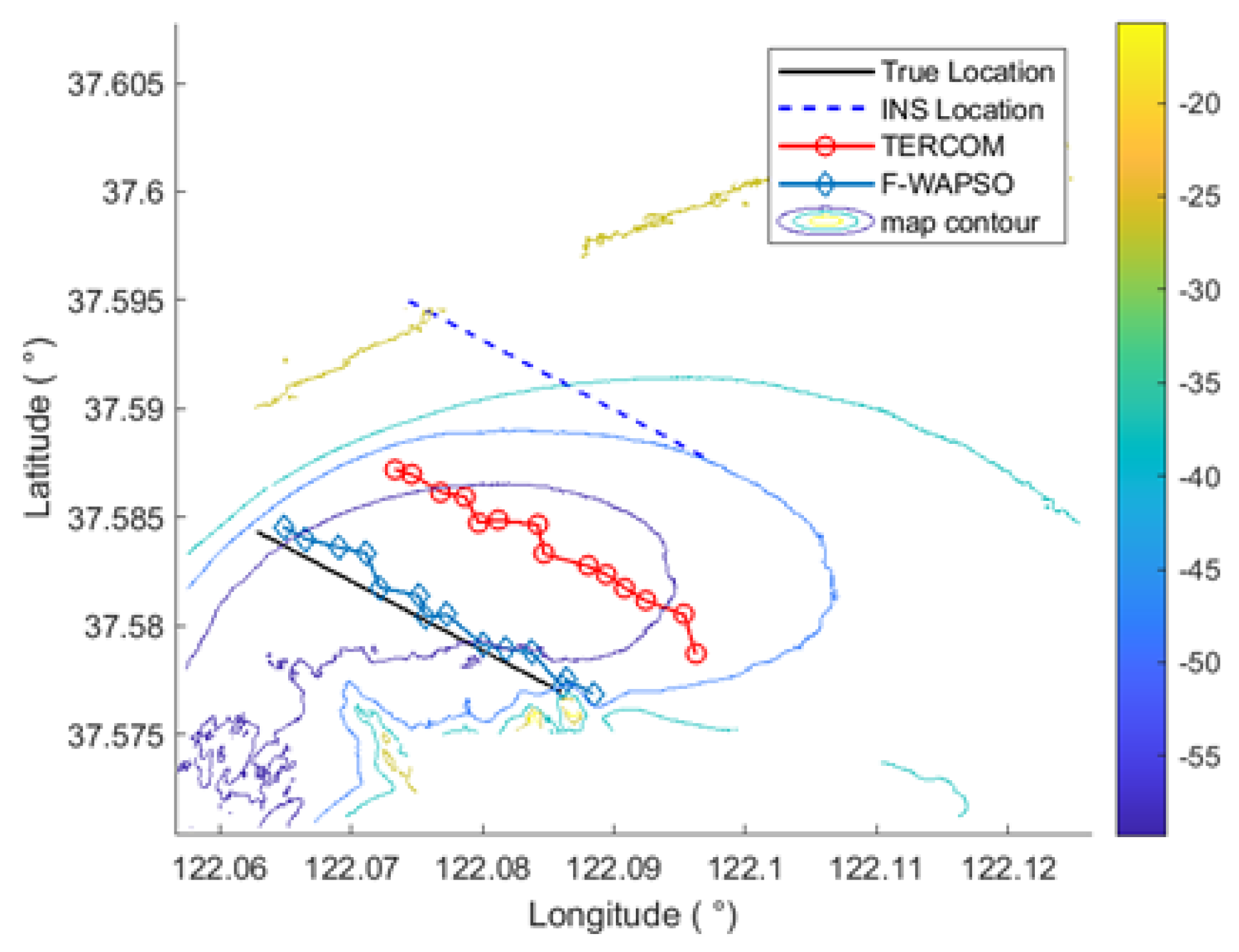
Trajectory C: the initial position of the underwater vehicle was 122.086° E, 37.577° N. The initial position of INS was 300 m to the east, and 300 m to the north; the initial course was 150° north by east, and the vehicle traveled straight at a constant speed. Figure 8 shows the trajectories of the two matching algorithms. Figure 9 shows the longitude and latitude error curves of trajectory C.
In Figure 8, F-WAPSO has remarkably better matching accuracy than TERCOM. In Figure 9, the longitude error of TERCOM decreases gradually between 200 and 50 m, whereas that of F-WAPSO is between −50 and 50 m. Furthermore, the latitude error of TERCOM oscillates around −100 m, whereas that of F-WAPSO oscillates around 0 m. Table 5 lists the statistical results of trajectory C.
Trajectory D: the initial position of the underwater vehicle was 122.086° E, 37.577° N. The initial position of INS was 700 m to the east, and 700 m to the north; the initial course was 150° north by east, and the vehicle traveled straight at a constant speed. Figure 10 shows the trajectories of the two matching algorithms. Figure 11 shows the longitude and latitude error curves of trajectory D.
In Figure 10, F-WAPSO has remarkably better matching accuracy than TERCOM. In Figure 11, the longitude error of TERCOM is between −150 and 50 m, whereas that of F-WAPSO oscillates around 0 m. Furthermore, the latitude error of TERCOM is between −50 and 300 m, whereas that of F-WAPSO is between −100 and 200 m. Table 6 lists the statistical results of trajectory D.
In conclusion, under the same conditions, when the initial position error is small, both TERCOM and F-WAPSO have a good matching effect, but when the initial position error is large, F-WAPSO has a better matching effect than TERCOM. As shown in Table 3, Table 4, Table 5 and Table 6, when the initial position error is (300 m, 300 m), compared with TERCOM, the matching error of F-WAPSO decreases by up to 80.1%, the longitude error decreases by up to 96.8%, the latitude error decreases by up to 88.6%, and the matching time decreases by up to 13.3%. When the initial position error is (700 m, 700 m), the matching error, longitude error, and latitude error of F-WAPSO are reduced by 63.3%, 92.4%, and 66.5% compared with TERCOM, and the matching time is shortened by 15.4%. When the initial position error is (1000 m, 1000 m), the matching error, longitude error, and latitude error of F-WAPSO are reduced by 57.1%, 94.3%, and 82.8% compared with TERCOM, and the matching time is shortened by 13.8%. With the increase of the initial position error, the matching error of the two algorithms increases and the matching time becomes longer. However, regardless of the size of the initial position error, the matching accuracy of F-WAPSO is obviously better than that of TERCOM, and the error variance of F-WAPSO is smaller in the four cases, indicating that F-WAPSO is more stable.

6. Conclusions

A new terrain matching algorithm, F-WAPSO, which combines ABC and PSO, able to reduce the cumulative error of inertial navigation, is proposed in this paper. F-WAPSO first improves the acceleration factor and inertia weight of the traditional PSO, respectively, to improve the convergence speed and global optimization ability of PSO. Secondly, ABC is introduced into the improved PSO to further reduce the occurrence of local optimization of the improved PSO. F-WAPSO was applied to terrain matching in inertial navigation. The results show that the matching accuracy of F-WAPSO is better than that of TERCOM, and the matching time is the shortest regardless of the initial errors. Even if the initial error is large, F-WAPSO improves the matching accuracy and reduces the matching time. F-WAPSO greatly improves the effect of terrain matching, effectively solves the problem of cumulative errors in INS, and fulfills the requirements of autonomous and accurate navigation of AUVs. The matching results of this new algorithm have a certain significance for potentially contributing to the successful correction of inertial navigation positions.

Author Contributions

Conceptualization, D.W. and L.L.; methodology, D.W. and P.D.; software, D.W., P.D. and J.W.; validation, D.W., L.L. and Y.B.; formal analysis, D.W. and Y.B.; investigation, J.W. and Y.B.; resources, Y.B.; data curation, D.W., Y.B. and J.W.; writing—original draft preparation, D.W.; writing—review and editing, L.L. and Y.B.; visualization, D.W.; supervision, Y.B.; project administration, Y.B.; funding acquisition, L.L. All authors have read and agreed to the published version of the manuscript.

Funding

This research was funded by the National key research and development program of China (grant number 2021YFC2801300) and the National key research and development program of China (grant number 2020YFE0202600).

Institutional Review Board Statement

Not applicable.

Informed Consent Statement

Not applicable.

Data Availability Statement

Not applicable.

Conflicts of Interest

The authors declare no conflict of interest.

References

  1. Lv, P.F.; He, B.; Guo, J.; Shen, Y.; Yan, T.H.; Sha, Q.X. Underwater navigation methodology based on intelligent velocity model for standard AUV. Ocean. Eng. 2020, 202, 107073. [Google Scholar] [CrossRef]
  2. Wang, D.; Xu, X.S.; Yao, Y.Q.; Zhang, T.; Zhu, Y.T. A novel SINS/DVL tightly integrated navigation method for complex environment. IEEE Trans. Instrum. Meas. 2020, 69, 5183–5196. [Google Scholar] [CrossRef]
  3. Melo, J.; Matos, A. Survey on advances on terrain based navigation for autonomous underwater vehicles. Ocean. Eng. 2017, 139, 250–264. [Google Scholar] [CrossRef] [Green Version]
  4. Chang, L.B.; Qin, F.J.; Wu, M.P. Gravity disturbance compensation for Inertial Navigation System. IEEE Trans. Instrum. Meas. 2019, 68, 3751–3765. [Google Scholar] [CrossRef]
  5. Zhang, Q.Q.; Zhao, L.; Zhou, J.H.; Wang, B.H.; Zhang, Y.P. A real-time airborne terrain aided inertial navigation system and its performance analysis. Adv. Space Res. 2017, 60, 2751–2762. [Google Scholar] [CrossRef]
  6. Wang, K.D.; Zhu, T.Q.; Qin, Y.J.; Rui, J.; Yong, L. Matching error of the iterative closest contour point algorithm for terrain-aided navigation. Aerosp. Sci. Technol. 2018, 73, 210–222. [Google Scholar] [CrossRef]
  7. Han, Y.R.; Wang, B.; Deng, Z.H.; Fu, M. A Combined matching algorithm for underwater gravity-aided navigation. IEEE-ASME Trans. Mechatron. 2018, 23, 233–241. [Google Scholar] [CrossRef]
  8. Han, Y.R.; Wang, B.; Deng, Z.H.; Wang, S.; Fu, M. A mismatch diagnostic method for TERCOM-based underwater gravity-aided navigation. IEEE Sens. J. 2017, 17, 2880–2888. [Google Scholar] [CrossRef]
  9. Wei, E.H.; Dong, C.J.; Yang, Y.L.; Tang, S.; Liu, J.; Gong, G.; Deng, Z. A Robust solution of integrated SITAN with TERCOM algorithm: Weight-reducing iteration technique for underwater vehicles’ gravity-aided inertial navigation system. Navig.-J. Inst. Navig. 2017, 64, 111–122. [Google Scholar] [CrossRef]
  10. Yuan, G.N.; Tan, J.L.; Liu, L.Q. Seabed terrain match algorithm based on Hausdorff distance and particle swarm optimization. In Proceedings of the International Joint Conference on Computational Sciences and Optimization, Sanya, China, 24–26 April 2009. [Google Scholar]
  11. Cheng, X.H.; Zhou, Y.H. Underwater terrain-aided navigation method based on improved particle swarm optimization. J. Chin. Inert. Technol. 2017, 25, 770–775. [Google Scholar]
  12. Xin, J.F.; Li, S.X.; Sheng, J.L.; Zhang, Y.B.; Cui, Y. Application of improved particle swarm optimization for navigation of unmanned surface vehicles. Sensors 2019, 19, 3096. [Google Scholar] [CrossRef] [PubMed]
  13. Bejarbaneh, E.Y.; Masoumnezhad, M.; Armagnani, D.J.; Pham, B.T. Design of robust control based on linear matrix inequality and a novel hybrid PSO search technique for autonomous underwater vehicle. Appl. Ocean Res. 2020, 101, 102231. [Google Scholar] [CrossRef]
  14. Ji, C.J.; Chen, Q.W.; Song, C.Y. Improved Particle Swarm Optimization Geomagnetic Matching Algorithm Based on Simulated Annealing. IEEE Access 2020, 8, 226064–226073. [Google Scholar] [CrossRef]
  15. Salavasidis, G.; Munafo, A.D.; Mcphail, S.; Harris, C.; Fenucci, D.; Pbody, M.; Rogers, E.; Phillips, A. Terrain-aided navigation with coarse maps-toward an arctic crossing with an AUV. IEEE J. Ocean. Eng. 2021, 46, 1192–1212. [Google Scholar] [CrossRef]
  16. Zhou, L.; Cheng, X.H.; Zhu, Y.H.; Dai, C.X.; Fu, J.B. An Effective Terrain Aided Navigation for Low-Cost Autonomous Underwater Vehicles. Sensors 2017, 17, 680. [Google Scholar] [CrossRef] [Green Version]
  17. Li, P.J.; Sheng, G.L.; Zhang, X.F.; Wu, J.Q.; Xu, B.C.; Liu, X.; Zhang, Y. Underwater terrain-aided navigation system based on combination matching algorithm. ISA Trans. 2018, 78, 80–87. [Google Scholar] [CrossRef] [PubMed]
  18. Li, S.F.; Cheng, C.Y. Particle swarm optimization with fitness adjustment parameters. Comput. Ind. Eng. 2017, 113, 831–841. [Google Scholar] [CrossRef]
  19. Isiet, M.; Gadala, M. Self-adapting control parameters in particle swarm optimization. Appl. Soft Comput. 2019, 83, 105653. [Google Scholar] [CrossRef] [Green Version]
  20. OuYang, H.B.; Gao, L.Q.; Li, S.; Kong, X.Y. Improved global-best-guided particle swarm optimization with learning operation for global optimization problems. Appl. Soft Comput. 2017, 52, 987–1008. [Google Scholar] [CrossRef]
  21. Zhao, Y.H.; Yan, Q.S.; Zheng, Y.; Yu, X.L.; Jia, B.Y. A Novel Artificial Bee Colony Algorithm for Structural Damage Detection. Adv. Civ. Eng. 2020, 2020, 3743089. [Google Scholar] [CrossRef] [Green Version]
  22. Hu, P.; Deng, C.S.; Wu, Z.J. Best neighbor-guided artificial bee colony algorithm for continuous optimization problems. Soft Comput. 2019, 23, 8723–8740. [Google Scholar]
  23. Xue, Y.; Jiang, J.M.; Zhao, B.P.; Ma, T. A self-adaptive artificial bee colony algorithm based on global best for global optimization. Soft Comput. 2018, 22, 2935–2952. [Google Scholar] [CrossRef]
  24. Liu, J.; Meng, L.Z. Integrating Artificial Bee Colony Algorithm and BP Neural Network for Software Aging Prediction in IOT Environment. IEEE Access 2019, 7, 32941–32948. [Google Scholar] [CrossRef]
  25. Liu, F.M.; Li, F.M.; Lin, N.; Jing, X. Gravity aided positioning based on real-time ICCP with optimized matching sequence length. IEEE Access 2019, 7, 97440–97456. [Google Scholar] [CrossRef]
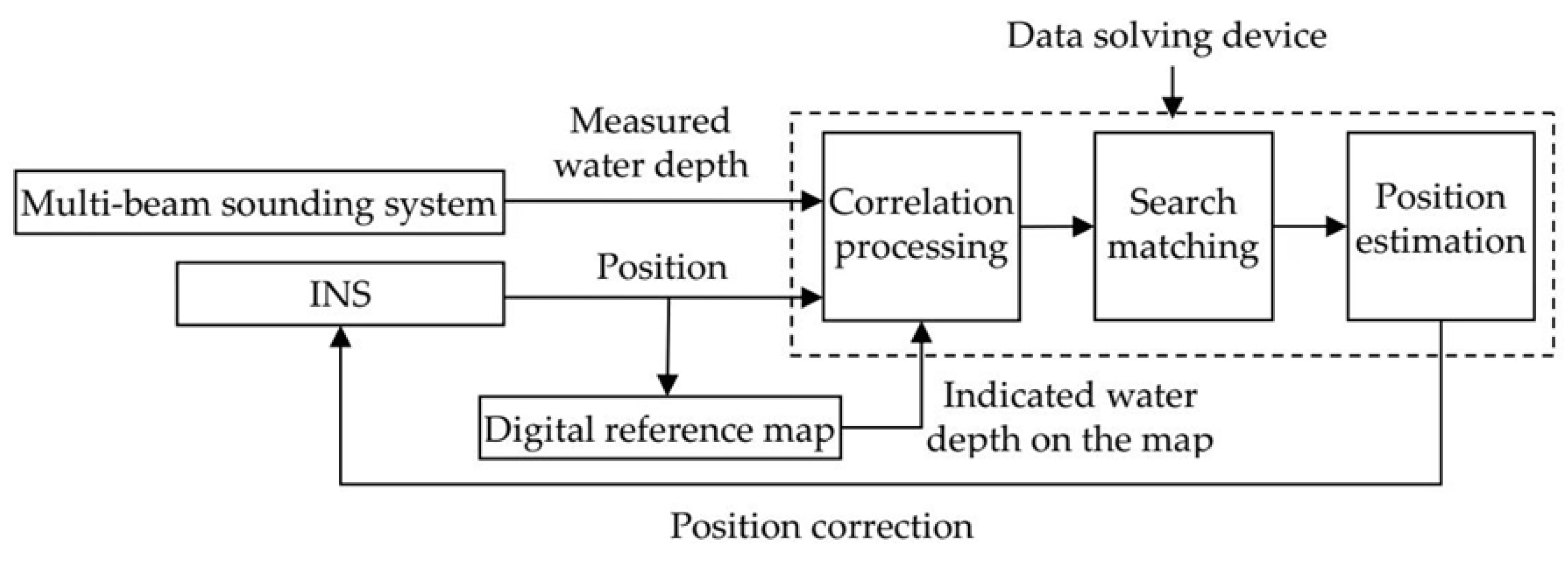
Figure 1. The principle of TAN.
Applsci 13 01166 g001
Figure 2. The flow chart of F-WAPSO.
Applsci 13 01166 g002
Figure 3. Two-dimensional and three-dimensional isobath graphs of the sea area.
Applsci 13 01166 g003
Figure 4. Trajectory A matching results of the two algorithms.
Applsci 13 01166 g004
Figure 5. Longitude and latitude error curves of trajectory A.
Applsci 13 01166 g005
Figure 6. Matching results of the two algorithms.
Applsci 13 01166 g006
Figure 7. Longitude and latitude error curves of trajectory B.
Applsci 13 01166 g007
Figure 8. Trajectory C matching results of the two algorithms.
Applsci 13 01166 g008
Figure 9. Longitude and latitude error curves of trajectory C.
Applsci 13 01166 g009
Figure 10. Trajectory D matching results of the two algorithms.
Applsci 13 01166 g010
Figure 11. Longitude and latitude error curves of trajectory D.
Applsci 13 01166 g011
Table 1. The steps of WAPSO.
 WAPSO
Parameter: τ max , number of particles, ω , c1, c2
1.
Initialize the swarm
2.
Evaluate the swarm
3.
τ = 1
4.
while τ τ m a x do
5.
for every particle i do
6.
Update all particles’ velocities and positions according to Equations (5) and (6)
7.
if f ( p b e s t i ) f ( x i ) then p b e s t i = x i
8.
end if
9.
end for
10.
Update gbest
11.
τ = τ + 1
12.
end while
13.
return gbest
Table 2. The pseudocode of F-WAPSO.
 F-WAPSO
1.
set τ max , number of particles, ω , c1, c2
2.
randomly initialize the swarm
3.
calculate the fitness value of each particle
4.
τ = 1
5.
while τ τ max do
6.
for every particle i do
7.
update xi and vi according to Equations (5) and (6)
8.
update pbest and gbest
9.
for every particle i do
10.
perform ABC search according to Equations (15)–(18)
11.
update pbest and gbest
12.
end for
13.
τ = τ + 1
14.
end while
15.
return gbest
Table 3. Matching and error statistics of the two algorithms for trajectory A.
Matching
Algorithm
Initial Position
Error
Matching
Error (m)
Matching Time (s)Error of
Longitude (m)
Error of
Latitude (m)
Error
Variance
TERCOM(300 m, 300 m)151.62.9819.2−147.629.1
F-WAPSO(300 m, 300 m)30.12.750.62−16.817.1
Table 4. Matching and error statistics of the two algorithms for trajectory B.
Matching
Algorithm
Initial Position ErrorMatching Error (m)Matching Time (s)Error of
Longitude (m)
Error of Latitude (m)Error
Variance
TERCOM(1000 m, 1000 m)218.115.9138168.963.6
F-WAPSO(1000 m, 1000 m)93.513.7−7.8−29.148.3
Table 5. Matching and error statistics of the two algorithms for trajectory C.
Matching
Algorithm
Initial Position
Error
Matching Error (m)Matching Time (s)Error of
Longitude (m)
Error of
Latitude (m)
Error
Variance
TERCOM(300 m, 300 m)144.14.5129.4−53.623.7
F-WAPSO(300 m, 300 m)33.63.9−16.6−27.518.8
Table 6. Matching and error statistics of the two algorithms for trajectory D.
Matching
Algorithm
Initial Position
Error
Matching Error (m)Matching Time (s)Error of
Longitude (m)
Error of
Latitude (m)
Error
Variance
TERCOM(700 m, 700 m)162.514.9−51.3147.638.5
F-WAPSO(700 m, 700 m)59.712.6−3.949.533.6
Disclaimer/Publisher’s Note: The statements, opinions and data contained in all publications are solely those of the individual author(s) and contributor(s) and not of MDPI and/or the editor(s). MDPI and/or the editor(s) disclaim responsibility for any injury to people or property resulting from any ideas, methods, instructions or products referred to in the content.