Abstract
Solving a scalar wave equation by the finite-difference (FD) method is a key step for advanced seismic imaging, in which the numerical accuracy is significantly affected by the FD stencil. High-order spatial and temporal approximations of the FD stencil can effectively improve the numerical accuracy and mitigate dispersion error. However, the huge costs of high-order stenciling in computation and storage hinder the application of large-scale modeling. In this paper, we propose a new efficient FD stencil with high-order temporal accuracy for numerical seismic modeling. The new stencil has a radial shape, including a standard cross-stencil and a rotated cross-stencil with a degree, and it can reach sixth-order accuracy in the time approximation. Compared with the well-known temporal high-order cross-rhombus stencil, the new stencil involves fewer grid nodes and thus has higher computational efficiency, especially in high-order cases. Dispersion and stability analyses show that the new stencil has great improvements in mitigating the dispersion error and stability problem compared with the conventional methods. Numerical accuracy and execution time analyses show that the new stencil is an economical and feasible method for large-scale modeling.
1. Introduction
Finite-difference methods are the most popular tool for understanding complex wave phenomena due to their straightforward implementation and relatively small computational cost [1,2,3,4,5,6,7]. Solving scalar wave equations through FD methods is a basic step in seismic depth migration [8] and velocity modeling [9,10,11]. An FD stencil defines the grid nodes related to the FD operator, such as the widely used cross-stencil involving a series of horizontal and vertical grid nodes. High-order FD stencils for approximating temporal derivatives have practical advantages in mitigating dispersion errors and stability problems.
To obtain an FD stencil with high-order time approximation, the authors of [1] presented a Lax–Wendroff scheme in which the high-order FD operators of the temporal derivatives are transformed into the FD operators of the mixed spatial derivatives. The authors of [12,13] further developed this method with fourth- and sixth-order temporal accuracies and derived a stability formula for the scalar wave equation. Afterward, in [14], the authors presented a new FD stencil with a rhombus shape. The rhombus stencil is also similar to the Lax–Wendroff method, and it can reach arbitrary even-order accuracy for both the temporal and spatial accuracies. To improve the computational efficiency, the authors of [15] presented a mixed stencil with a small rhombus stencil and a large cross stencil. They demonstrated that this cross-rhombus stencil can reach (2M)th-order spatial and (2N)th-order temporal accuracies with the time–space domain FD coefficients. The authors of [16,17] further developed the cross-rhombus stencil in a staggered grid and gave the analytical formula for solving FD coefficients with fourth- and sixth-order temporal accuracies. Then, the authors of [18] presented a method for solving FD coefficients with arbitrary even-order accuracies in a staggered grid and investigated the optimal FD coefficients using a combination of the Taylor series expansion and least squares method.
A standard cross-rhombus stencil with a high-order time approximation will involve more grid nodes, thus increasing the cost exponentially. For the problem of low computational efficiency in high-order cases, we propose a new temporal high-order FD stencil. The new stencil has a radial shape, including a standard cross-stencil and a rotated cross-stencil with a degree, in which the rotated cross stencil is similar to the Lax–Wendroff approach to improve the temporal accuracy. Compared with the standard cross-rhombus stencil method, the new stencil involves fewer grid nodes, and this is significant for reducing computational costs in large-scale seismic modeling. We prove that the new stencil can reach sixth-order temporal accuracy with the time–space domain FD coefficients. Although the new stencil cannot guarantee higher accuracy than the sixth-order time approximation, it is a compromise scheme which sacrifices a little accuracy in exchange for a large increase in computational efficiency. Then, we use the Taylor-series expansion (TE) method [19] to obtain the FD coefficients of the proposed FD stencil. As an alternative, we present the dispersion relationship-preserving (DRP) method [6,7,20,21] to obtain the FD coefficients satisfying more elevated wavenumbers in the dispersion relationship. The DRP-based FD coefficients can effectively mitigate the dispersion errors from the high-wavenumber components. To verify the feasibility of the proposed method, we designed a series of experiments to analyze the performance of the new stencil. The results indicate that the new stencil is a significant improvement in mitigating dispersion error and computational efficiency compared with the conventional methods.
2. Method
2.1. Review of the Staggered-Grid FD Scheme with the Cross-Rhombus Stencil
The 2D constant density scalar wave equation for space and time t can be expressed as follows:
where is the scalar wavefield and v is the velocity. The Taylor expansion of Equation (1) with respect to time [1] yields
Here, is the discretized scalar wavefield, is the time step, and represents the weights of the spatial mixed derivatives. Then, Equation (2) can be approximated by the FD operator with a cross-rhombus stencil such that
Here, , h represents the grid spacing and is the Courant number, where the parameters M and N define the size of the cross- and rhombus stencils, respectively. The cross-rhombus stencil can achieve (2M)th-order spatial and (2N)th-order temporal accuracies when the FD coefficients are derived from the time–space domain dispersion relation [15].
2.2. A New Efficient FD Stencil with High-Order Spatial and Temporal Accuracies
To further improve the computational efficiency, we simplify the cross-rhombus stencil to a new FD stencil with a radial shape. As shown in Figure 1, the new stencil involves grid nodes only with degrees, where n is an arbitrary integer. Compared with the standard cross-rhombus stencil, the new stencil has less grid nodes, especially in the high-order cases. We can prove that the stencil still has a higher-order temporal approximation, and the details of the proof are shown in Appendix A.
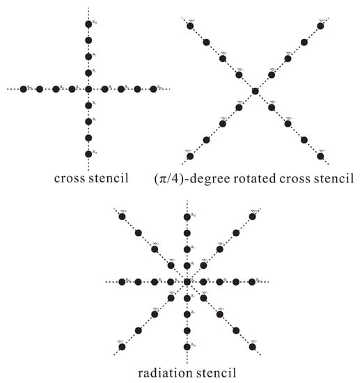
Figure 1.
Schematic diagram of the new stencil, where the new radiation stencil is composed of a standard cross-stencil and a rotated cross-stencil of degrees.
According to the definition of the new stencil (Figure 1), we obtained the new FD scheme:
The new radiation stencil is a combination of a standard cross-stencil and a rotated cross-stencil with degrees (Figure 1). Let represent the FD coefficients of the standard cross-stencil and represent the FD coefficients of the rotated cross-stencil. In the following parts, we present two methods to obtain the FD coefficients of the proposed stencil and analyze the approximate accuracy theoretically.
2.3. Determining FD Coefficients of the New Stencil through Taylor-Series Expansion
Assuming the plane wave propagates in the grid, we let
Here, , , and is the propagation direction of the plane wave, while represents the angular frequency. By substituting Equation (5) into Equation (4), we obtain
Equation (6) represents the time–space domain dispersion relation of our new FD scheme. Let . The Taylor-series expansions of the cosine functions , and give
When comparing the coefficients of (), we obtain
Let
When comparing the weights of , we obtain
We only need independent equations to solve the FD coefficients and . Through redundancy analysis, we simplify Equation (11) as
where represents a function to find the integer part of the real value. In Appendix A, we prove that the FD coefficients obtained by Equation (12) can reach at least sixth-order temporal accuracy. Aside from that, we give the solution of Equation (12) in an analytic form when , and the details are shown in Appendix B. Next, we analyze the relationship between the new stencil and some existing methods:
(1) When and (for example, and ), this is a general situation, and Equation (12) can be expressed as
The FD coefficients and can be determined by solving the above linear equation, and can be determined by Equation (8).
(2) When , there is no rotated cross-stencil. Equation (12) can be simplified as follows:
The new FD scheme is simplified to the conventional time–space domain FD scheme with a cross-stencil [19].
(3) When , Equation (12) becomes the fourth-order temporal accuracy FD scheme with a cross-rhombus stencil [14,15].
(4) When , the FD coefficients , Equation (12) can be expressed as
In this case, the new FD scheme is simplified to the space domain FD scheme with a cross-stencil.
2.4. Determining the FD Coefficients of the New Stencil with the Dispersion Relationship-Preserving Method
TE-based FD coefficients are prone to dispersion errors for the high-wavenumber components [17,22]. As an alternative, we present the dispersion relationship-preserving method to obtain FD coefficients satisfying more elevated wavenumbers in the dispersion relationship [6,7,20,21]. The DRP-based FD coefficients can effectively mitigate the dispersion errors from the high-wavenumber components. Following our previous work [7], we define a new function to represent the weights of the FD coefficients in the dispersion relation (Equation (6)). Then, can be defined as
Here, , and represents the propagation angle. Similarly, we define another function to represent the weights of . The function can be defined as
Then, we can extend to matrix involving a series of and a fixed angle . Matrix is
where and can be obtained by the optimization algorithm [23]. We also extend the function to the matrix
Additionally, the right-hand side of Equation (6) is expanded to
Thus, the time–space domain dispersion relation of our new method involving wavenumbers and angles can be expressed as follows:
Then, numerically solving this over-determined system can yield the DRP-based FD coefficients.
3. Dispersion Analysis
We denote the phase velocity and then yield the phase velocity ratio
Here, q is
In addition, . We analyze and compare the ratios of different FD methods, and the abbreviations of these FD methods are listed in Table 1. Figure 2 shows the ratios varying with parameters and .

Table 1.
Abbreviation table of different FD methods used for dispersion analyses.
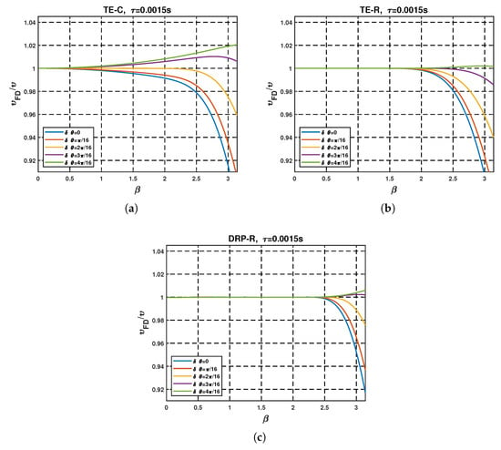
Figure 2.
Dispersion curves varying with the parameters and propagation angle . Here, (s), (m/s), (m), , and : (a) TE-C method, (b) TE-R method and (c) DRP-R method.
It is clear that the ratios of the TE-C method were far larger than one for the high-wavenumber region (Figure 2a), resulting in a serious temporal dispersion error. The corresponding ratios of the new method (Figure 2b) were significantly improved, indicating that the TE-R method can effectively mitigate the temporal dispersion error for the high-wavenumber components. Figure 2c shows that the DRP-R method had the smallest dispersion error compared with the other methods.
The TE-CR method will multiply the computational cost by the increase in the temporal order N. Then, we analyzed the ratios of the TE-CR and TE-R methods with different orders N, and the results are shown in Figure 3. It can be seen that the performance of the TE-R method was slightly less than that of the TE-CR method, but the cost of the TE-CR method increased exponentially in the high-order cases. Although the new stencil sacrificed a little approximation accuracy, it had great improvement in computational efficiency.
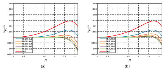
Figure 3.
Dispersion curves of TE-CR and TE-R methods with different orders N. Here, (m/s), (m), , and propagation angle : (a) TE-CR method and (b) TE-R method.
4. Stability Analysis
The function in Equation (6) must lie in the interval , where
We mostly use the Nyquist wavenumber to analyze the stability [19,24] such that
By substituting Equation (25) into Equation (24), we obtain the 2D stability condition of the proposed FD scheme as follows:
Then, the 2D stability factor s can be defined as
where the stability factor s is related to the FD coefficients, and these FD coefficients are determined by the Courant number r. Therefore, the FD scheme must satisfy the following stability condition:
In the following, we analyze the stability factors s varying with the Courant number r, and the results are shown in Figure 4. It can be seen that the TE-C method had the smallest stability factor, indicating that it is prone to instability. The stability factors of the TE-R and DRP-R methods were slightly less than the TE-CR method but much larger than that of the TE-C method. Figure 4b shows the maximum factor s satisfying for different orders M. The maximum stability factors of the TE-R and DRP-R methods were obviously larger than that of the TE-C method, which showed an improvement in stability.
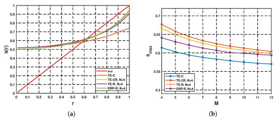
Figure 4.
Stability curves of different FD methods: (a) stability factors varying with the Courant numbers r and (b) maximum stability factors satisfying with different orders M.
5. Numerical Experiments
5.1. Seismic Modeling of a 2D Homogeneous Velocity Model
In this section, we use a 2D homogeneous velocity model to examine our new stencil. The 2D homogeneous model had grid nodes with a velocity (m/s). We set , and a time step (s) for the FD methods. A Ricker wavelet with 40 (Hz) was injected as an explosion source. Figure 5 shows the snapshots of different methods with grid sampling (m) and (m).
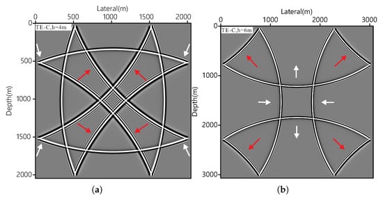
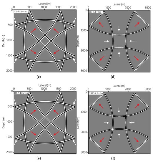
Figure 5.
Numerical experiments of the homogeneous model with grid sampling (m) and (m). The left panel shows the snapshots with the grid sampling (m), and the right panel represents the grid sampling (m): (a,b) TE-C method, (c,d) TE-R method and (e,f) DRP-R method.
It can be seen that the TE-C method had visible temporal dispersion errors (red arrows) with the grid sampling (m) and had both serious spatial (white arrows) and temporal dispersion errors with the grid sampling (m). The corresponding temporal dispersion errors were reduced in the TE-R method, indicating that the new stencil had better temporal accuracy. The spatial dispersion errors were significantly reduced in the DRP-R method. Thus, the DRP-based FD coefficients could effectively mitigate the spatial dispersion with a large grid spacing.
5.2. Numerical Accuracy and CPU Execution Time Analyses
An increase in the temporal order N will significantly increase the computational cost. In this part, we set a series of temporal orders N to analyze the relative errors and CPU execution times (CPU: AMD 5600h) of the cross-rhombus stencil and our new stencil. Here, we adopted (m), (s) and (m/s) for all FD methods. We set up three receivers at positions (m), (m) and (m), which represent the simulations of different propagation angles. We calculated their total relative errors with the reference method [7], and the total relative error was defined as
where represents the records of the three receivers and represents the records of the references.
Table 2 lists the total relative errors and CPU execution times of the TE-R and TE-CR methods with different orders N. It can be seen that the relative errors of the TE-CR method were slightly less than that of the TE-R method (Table 2). However, the CPU execution times of the TE-CR method were much larger than that of the TE-R method. Table 2 demonstrates that the numerical accuracy of the new method was slightly lower than that of the standard cross-rhombus stencil, but its computational efficiency was greatly improved, especially in the high-order cases.

Table 2.
Relative errors and CPU execution times of the TE-CR and TE-R methods with different orders N.
5.3. Seismic Modeling of the 2D Inhomogeneous Velocity Model
We used a modified 2D Sigsbee velocity model to test the new stencil in the complex velocity model. The modified Sigsbee model (Figure 6) has grid nodes, with the velocities varying from 1550 to 4500 (m/s). We set , , grid spacing (m) and the time step (s) for all FD schemes. The source with the peak frequency (Hz) (Ricker wavelet) was injected at the center of the surface. For convenience, we ignored the influence of the discrete grid representation on the strong material interfaces [25,26].
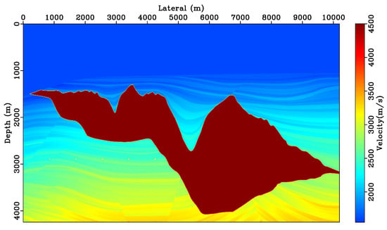
Figure 6.
The 2D Sigsbee model had grid nodes with a grid spacing (m) and variation in the velocities from 1550 to 4500 (m/s).
Figure 7 shows the snapshots and seismic records of different FD methods. The TE-C method had obvious dispersion errors in the low-velocity layers, while the corresponding dispersion errors were reduced in the TE-R and DRP-R methods. Figure 8 shows the seismic records at position (m), at which the reference trace r used a high-order temporal and spatial FD scheme () with the DRP-based coefficients [7]. Traces a-r b-r and c-r represent the relative errors of the TE-C, TE-R and DRP-R methods compared with the reference method, respectively. The dispersion errors of the TE-C method were serious for the first arrival waves and reflection waves. The corresponding errors were significantly alleviated in the TE-R and DRP-R methods. Table 3 lists the relative errors of all FD methods. It is clear that the relative errors of the TE-R and DRP-R methods were far less than that of the TE-C method. The numerical experiments with the Sigsbee model demonstrated that the new stencil also had better performance in the complex velocity model for mitigating dispersion errors.
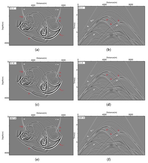
Figure 7.
Snapshots and corresponding seismic records of the 2D Sigsbee velocity model. Here, , , (s) and (m). (a,b) The TE-C method. (c,d) The TE-R method. (e,f) The DRP-R method.
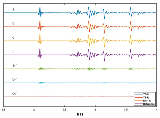
Figure 8.
Seismogram at position (m) of different FD methods. Trace a represents the record of the TE-C method. Trace b represents the TE-R method. Trace c represents the DRP-R method. Trace r represents the reference trace. Trace a-r represents the relative error between trace a and reference trace r. Trace b-r represents the relative error of trace b. Trace c-r represents the relative error of trace c.

Table 3.
Relative errors of different FD methods in the 2D Sigsbee velocity model.
6. Conclusions
In this work, we proposed a new FD stencil with high-order temporal and spatial accuracies. The new stencil can reach at least sixth-order temporal accuracy and involves fewer grid nodes than that of the well-known cross-rhombus stencil. We presented two methods to solve the FD coefficients of the new stencil by Taylor-series expansion and the dispersion relationship-preserving method, in which the DRP-based FD coefficients can effectively mitigate the dispersion errors from the high-wavenumber components. Dispersion, stability analyses and numerical experiments demonstrated that the new stencil had better accuracy and stability than those of the conventional cross-stencil. Numerical accuracy and execution time analyses proved that the accuracy of the new stencil was slightly lower than that of the standard cross-rhombus stencil in the high-order cases, but its computational efficiency was greatly improved. Thus, the new stencil is a more economical and feasible method for large-scale modeling.
Author Contributions
Conceptualization, G.C. and Y.L.; methodology, G.C.; validation, Z.P.; formal analysis, G.C.; investigation, G.C.; resources, Y.L.; writing—original draft preparation, G.C.; writing—review and editing, Z.P. and Y.L.; visualization, G.C.; supervision, Z.P.; project administration, Z.P.; funding acquisition, Z.P. All authors have read and agreed to the published version of the manuscript.
Funding
This work was supported by the Natural Science Foundation of the Sichuan Province of China (Grant No. 2022NSFSC40574) and partially supported by the National Natural Science Foundation of China (Grant No. 61775030 and Grant No. 61571096).
Institutional Review Board Statement
Not applicable.
Informed Consent Statement
Not applicable.
Data Availability Statement
Not applicable.
Acknowledgments
This study benefited from the reproducible codes and documentation provided in Madagascar open-source software [27]. The authors appreciate the owner of the copyrights.
Conflicts of Interest
The authors declare no conflict of interest.The funders had no role in the design of the study or in the collection or analyses.
References
- Dablain, M. The application of high-order differencing to the scalar wave equation. Geophysics 1986, 51, 54–66. [Google Scholar] [CrossRef]
- van Vossen, R.; Robertsson, J.O.; Chapman, C.H. Finite-difference modeling of wave propagation in a fluid-solid configuration. Geophysics 2002, 67, 618–624. [Google Scholar] [CrossRef]
- Moczo, P.; Kristek, J.; Halada, L. 3D fourth-order staggered-grid finite-difference schemes: Stability and grid dispersion. Bull. Seismol. Soc. Am. 2000, 90, 587–603. [Google Scholar] [CrossRef]
- Etgen, J.T.; O’ Brien, M.J. Computational methods for large-scale 3D acoustic finite-difference modeling: A tutorial. Geophysics 2007, 72, SM223–SM230. [Google Scholar] [CrossRef]
- Moczo, P.; Kristek, J.; Gális, M. The Finite-Difference Modelling of Earthquake Motions: Waves and Ruptures; Cambridge University Press: Cambridge, UK, 2014. [Google Scholar]
- Etemadsaeed, L.; Moczo, P.; Kristek, J.; Ansari, A.; Kristekova, M. A no-cost improved velocity-stress staggered-grid finite-difference scheme for modelling seismic wave propagation. Geophys. J. Int. 2016, 207, 481–511. [Google Scholar] [CrossRef]
- Chen, G.; Wang, Y.; Wang, Z.; Zhang, S. Dispersion-relationship-preserving seismic modelling using the cross-rhombus stencil with the finite-difference coefficients solved by an over-determined linear system. Geophys. Prospect. 2020, 68, 1771–1792. [Google Scholar] [CrossRef]
- Baysal, E.; Dan, D.K.; Sherwood, J. Reverse-Time Migration. Geophysics 1983, 48, 1514–1524. [Google Scholar] [CrossRef]
- Virieux, J.; Operto, S. An overview of full-waveform inversion in exploration geophysics. Geophysics 2009, 74, WCC1–WCC26. [Google Scholar] [CrossRef]
- Chen, G.; Wang, Z. Robust full-waveform inversion based on particle swarm optimization. In SEG Technical Program Expanded Abstracts 2017; Society of Exploration Geophysicists: Houston, TX, USA, 2017; pp. 1302–1306. [Google Scholar] [CrossRef]
- Zhang, C.; Fan, L.; Chen, G.; Li, J. AVO-Friendly Velocity Analysis Based on the High-Resolution PCA-Weighted Semblance. Appl. Sci. 2022, 12, 6098. [Google Scholar] [CrossRef]
- Chen, J.B. High-order time discretizations in seismic modeling. Geophysics 2007, 72, SM115–SM122. [Google Scholar] [CrossRef]
- Chen, J.B. A stability formula for Lax-Wendroff methods with fourth-order in time and general-order in space for the scalar wave equation. Geophysics 2011, 76, T37–T42. [Google Scholar] [CrossRef]
- Liu, Y.; Sen, M.K. Time-space domain dispersion-relation-based finite-difference method with arbitrary even-order accuracy for the 2D acoustic wave equation. J. Comput. Phys. 2013, 232, 327–345. [Google Scholar] [CrossRef]
- Wang, E.; Liu, Y.; Sen, M.K. Effective finite-difference modelling methods with 2-D acoustic wave equation using a combination of cross and rhombus stencils. Geophys. J. Int. 2016, 206, 1933–1958. [Google Scholar] [CrossRef]
- Tan, S.; Huang, L. An efficient finite-difference method with high-order accuracy in both time and space domains for modelling scalar-wave propagation. Geophys. J. Int. 2014, 197, 1250–1267. [Google Scholar] [CrossRef]
- Tan, S.; Huang, L. A staggered-grid finite-difference scheme optimized in the time–space domain for modeling scalar-wave propagation in geophysical problems. J. Comput. Phys. 2014, 276, 613–634. [Google Scholar] [CrossRef]
- Ren, Z.; Li, Z.C. Temporal high-order staggered-grid finite-difference schemes for elastic wave propagationTemporal high-order SFD schemes. Geophysics 2017, 82, T207–T224. [Google Scholar] [CrossRef]
- Liu, Y.; Sen, M.K. A new time–Space domain high-order finite-difference method for the acoustic wave equation. J. Comput. Phys. 2009, 228, 8779–8806. [Google Scholar] [CrossRef]
- Ye, F.; Chu, C. Dispersion-relation-preserving finite difference operators: Derivation and application. In SEG Technical Program Expanded Abstracts 2005; Society of Exploration Geophysicists: Houston, TX, USA, 2005; pp. 1783–1786. [Google Scholar]
- Liang, W.; Wang, Y.; Yang, C. Determining finite difference weights for the acoustic wave equation by a new dispersion-relationship-preserving method. Geophys. Prospect. 2015, 63, 11–22. [Google Scholar] [CrossRef]
- Liu, Y. Globally optimal finite-difference schemes based on least squares. Geophysics 2013, 78, T113–T132. [Google Scholar] [CrossRef]
- Chen, G.; Peng, Z.; Li, Y. A framework for automatically choosing the optimal parameters of finite-difference scheme in the acoustic wave modeling. Comput. Geosci. 2022, 159, 104948. [Google Scholar] [CrossRef]
- Liu, Y.; Sen, M.K. Scalar Wave Equation Modeling with Time-Space Domain Dispersion-Relation-Based Staggered-Grid Finite-Difference Schemes. Bull. Seismol. Soc. Am. 2011, 101, 141–159. [Google Scholar] [CrossRef]
- Moczo, P.; Gregor, D.; Kristek, J.; de la Puente, J. A discrete representation of material heterogeneity for the finite-difference modelling of seismic wave propagation in a poroelastic medium. Geophys. J. Int. 2019, 216, 1072–1099. [Google Scholar] [CrossRef]
- Gregor, D.; Moczo, P.; Kristek, J.; Mesgouez, A.; Lefeuve-Mesgouez, G.; Kristekova, M. Subcell-resolution finite-difference modelling of seismic waves in Biot and JKD poroelastic media. Geophys. J. Int. 2020, 224, 760–794. [Google Scholar] [CrossRef]
- Fomel, S.; Sava, P.; Vlad, I.; Liu, Y.; Bashkardin, V. Madagascar: Open-source software project for multidimensional data analysis and reproducible computational experiments. J. Open Res. Softw. 2013, 1, e8. [Google Scholar]
Disclaimer/Publisher’s Note: The statements, opinions and data contained in all publications are solely those of the individual author(s) and contributor(s) and not of MDPI and/or the editor(s). MDPI and/or the editor(s) disclaim responsibility for any injury to people or property resulting from any ideas, methods, instructions or products referred to in the content. |
© 2023 by the authors. Licensee MDPI, Basel, Switzerland. This article is an open access article distributed under the terms and conditions of the Creative Commons Attribution (CC BY) license (https://creativecommons.org/licenses/by/4.0/).