Abstract
Turnouts are the weak spot in high-speed rail systems, and it is simple for the phenomenon of the wheel–rail force and the carbody lateral acceleration over-limit to arise when the train passes through, which affects the service life of the rail and the running stability of the train. In this paper, the turnout with wheel–rail force over-limit and carbody lateral acceleration over-limit is selected for analysis, and the profiles of the wheel and rail are monitored. Then, the vehicle–turnout coupled multi-body dynamics model is simulated. Additionally, the portable vibration analyzer, the comprehensive inspection train, and the wheel–rail contact dynamic stress tester monitors the data and evaluates the impact of rail grinding on high-speed railway. The results of this study demonstrated that the turnout profiles are in good agreement with the standard wheel profiles following grinding, and the wheel–rail contact point and equivalent conicity both improved. When the train passes the ground turnout at high speed with and without the wheel polygonal wear, the wheel–rail force and the carbody acceleration were clearly improved. Using the wheel–rail contact dynamic stress tester, the comprehensive inspection train, and the portable vibration analyzer monitoring the changes in the carbody acceleration, the wheel–rail force and the carbody acceleration are definitely better after grinding. Similar to the pattern in the simulation, the train’s running steadiness increased by grinding.
1. Introduction
Turnouts are one of the three weak links (joints, curves, and turnouts) of the high-speed rail system in China, where operating speeds and mileage are being steadily increased. Turnout rail deterioration is becoming more severe [1,2], and issues with the wheel–rail force over-limit and the carbody vibration acceleration over-limit phenomenon are frequent when trains pass through turnouts [3,4,5,6]. In order to effectively prolong the service life of the rail and improve the safety and stability of the trains, rail grinding is thought to be the most effective method of maintenance for turnout rail deterioration [7,8,9,10].
Some researchers have simulated rail surface damage using the finite element method, and they continuously monitor its evolution. Using the finite element method, Pletz et al. [11] created a dynamic model of a single wheel moving through the turnout’s crossing panel so they could study the dynamic interaction force between the wheel and rail and the internal equivalent stress. In addition to analyzing the hardness properties of high-speed railway turnouts, Xu et al. [12] proposed a transient analysis model based on the finite element method. At the same time, Xu et al. [13] evaluated and analyzed four models of wheel–rail rolling contact of railway turnout, which offered some recommendations for the choice of contact models. Some researchers have used dynamic methods to carry out a thorough evaluation of turnout rail surface deterioration because the finite element method can only be used to study the contact area for turnout studies. Kassa and Nielsen [14] used various multi-rigid-body system software to simulate, monitor, and evaluate the dynamic interaction between the vehicle and the turnout with the data gathered from the field test. Wheel–rail wear and rolling contact fatigue were investigated by Burgelman et al. [15] using vehicle–turnout coupled system dynamics. The dynamic simulation analysis of the vehicle–turnout system was conducted by Sebes et al. [16] using the wheel–rail half-Hertz contact algorithm, which can precisely resolve the wheel–rail contact spot shape and contact fatigue. The vehicle–turnout coupled dynamic model was used by Ma et al. [17] to monitor the contact fatigue of the turnout rail surface. These findings indicate that large tangential stress under conditions of low creep is the primary cause of the rail surface fatigue crack.
Using the finite element method and dynamic method, the causes of turnout deterioration can be monitored and evaluated, and some scholars have optimized the profile to reduce the surface deterioration of the turnout rail, such as Sugiyama et al.’s [18] optimization of the switch rail profile. In order to participate in the computation of wheel–rail contact fatigue, the profiles of the switch rail and the stock rail were integrated into a single profile at the same time. Wang et al. [19] proposed a technique for enhancing the switch rail profile in order to improve the stability and contact fatigue of high-speed turnouts. In light of the unusual wear on metro rails, Choi et al.’s [20] GA method was employed to optimize the design of the rail grinding profile. In order to create a new rail profile that would serve as a reference for rail grinding, Xu et al. [21] thoroughly evaluated the impact of rail grinding on the operating stability and wear development of high-speed trains.
The rail profile changes as a result of the wheel–rail force experienced by the moving train, departing greatly from the initially optimized profile. As a result, rail grinding is required to fix the altered rail profile. Meanwhile, rail grinding can also improve rail surface deterioration, so there has been a great deal of systematic research on rail grinding. In order to decrease rail wear and increase the service life of rails while also enhancing the dynamic performance of trains, Uhlmann et al. [22] adopted this strategy. Crystal orientation analysis, EBSP analysis, and X-ray diffraction axis density measurement were used by Satoh and Iwafuchi [23] to track the effects of rail grinding on the rolling contact fatigue of a conventional rail. Tyfour [24] examined how rail grinding and lubrication could reduce contact wear and fatigue. For the purpose of predicting the vibration properties of the rail both before and after grinding, Real et al. [25] created the numerical finite element model and the vehicle-track interaction model. With various grinding wheel materials and hardnesses, Wang et al. [26] monitored the grinding efficiency, grinding quality, and different types of grinding wheel wear. Theoretical support for rail grinding was provided by Zhou et al.’s [27] study of the effectiveness and quality of rail grinding at various grinding speeds.
Many scholars now study rail grinding for railway lines, while comparatively few study turnout rail grinding. Because the turnout is joined by various rail sections, the switch rails and the point rails are relatively weak, and there are numerous electronic equipment nearby, turnout grinding is more challenging than rail grinding of railway lines. The purpose of this study is to monitor and evaluate the grinding impact of high-speed railway turnout.
The basic configuration is as follows. Section 1 monitors the Hang-shen line to determine how the over-limit phenomenon of the wheel–rail force and the carbody lateral acceleration occurs when the trains pass through the turnout. Section 2 examines how the geometric properties of wheel–rail contact changed before and after grinding. The dynamic vehicle–turnout coupled model is established in Section 3. The turnout dynamics model takes into account the specific characteristics of its variable cross-section and variable stiffness, and the vehicle model selected the vehicle with the worst carbody lateral acceleration alarms. In Section 4, the dynamic characteristics of the train passing through the turnout are simulated and evaluated before and after grinding. In Section 5, the measured data of the wheel–rail force and the carbody acceleration when the trains pass through the turnout before and after grinding are monitored and evaluated. The results of additional research support the effect of turnout rail grinding.
2. Investigation of Field Measurement Problems
2.1. Wheel–Rail Force Monitoring
According to Chinese specification Testing of China railway high-speed electric multiple units on completion of construction [28], the wheel–rail lateral force limit of a high-speed train is 56 kN, and the wheel–rail vertical force limit of high-speed trains is 170 kN. The wheel–rail force limit values were obtained by Chinese railway experts and scholars through many dynamic performance tests on high-speed trains. If it exceeds this value, the trains may be dangerous.
The wheel–rail force is monitored by railway department employees using the wheel–rail contact dynamic stress tester (Figure 1b) as the train passes through a ground turnout, and the sampling frequency is about every half hour. The wheel–rail force of 42 sets of trains through the turnout was monitored each day from 10 June 2022 to 19 June 2022. Figure 1a displays the average wheel–rail maximum force for 42 sets of trains traveling at 250 km/h on a daily basis. There were 8 days of the average wheel–rail maximum lateral force over-limit and 7 days of the average wheel–rail maximum vertical force over-limit.
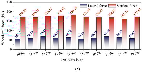
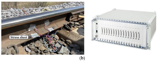
Figure 1.
Wheel–rail force test: (a) wheel–rail force test results; (b) wheel–rail contact dynamic stress tester from Jiangsu Donghua Testing Technology Co., Ltd. Jingjiang, Jiangsu, China.
2.2. Carbody Lateral Vibration Monitoring
According to Chinese specification Maintenance rules for ballasted track lines of high-speed railways [29], when the carbody lateral acceleration exceeds 0.6 m/s2, the level-one alarm appears, so it is necessary to carry out daily maintenance on the vehicles and track lines. The level-two alarm sounds when the carbody lateral acceleration exceeds 0.9 m/s2, and it is important to be concerned for both the safety of the vehicles and the track lines. A level-three alarm sounds when the carbody lateral acceleration exceeds 1.5 m/s2, necessitating temporary repairs to the vehicles and track lines. The speed limit of the vehicles is required when the carbody lateral acceleration exceeds 2.0 m/s2. A level-four alarm then sounds. The value of 0.5–10 Hz band-pass filtering is used to determine the level-one and level-two standards of carbody lateral acceleration, while the level-three and level-four standards are determined by the value of 10 Hz low-pass filtering.
The portable train vibration analyzer (Figure 2b) was used by railway department employees to test turnout from 10 June 2022 to 19 June 2022, as shown in Figure 2a. A total of 20 sets of high-speed trains were tested in all, 2 sets per day, 1 in the morning and 1 in the afternoon. The level-one alarm was activated four times, the level-two alarm was activated ten times, and the level-three alarm was activated six times as the trains passed through the turnout. A total of 50% of the warnings were level three or above (Figure 2c).

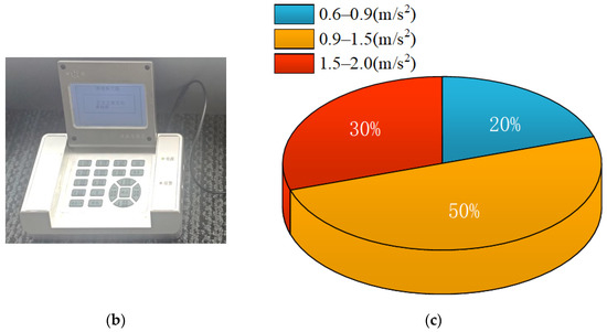
Figure 2.
Carbody acceleration test: (a) lateral acceleration test results; (b) portable tester from Bojie Gold Technology (Beijing) Co., Ltd. Beijing, China; (c) alarm statistics.
2.3. Wheel and Rail Evaluation
At the same time, using the feedback from the railway vehicle maintenance department, there was determined to be polygonal wear on the wheels. Due to multiple problems, further investigations on the vehicle wheels and the turnout rails were carried out. According to the measurement of the wheel profiles, there was polygonal wear on the wheels, as shown in Figure 3. The polygonal wear average depth was 0.015 mm, and the average order was 20.
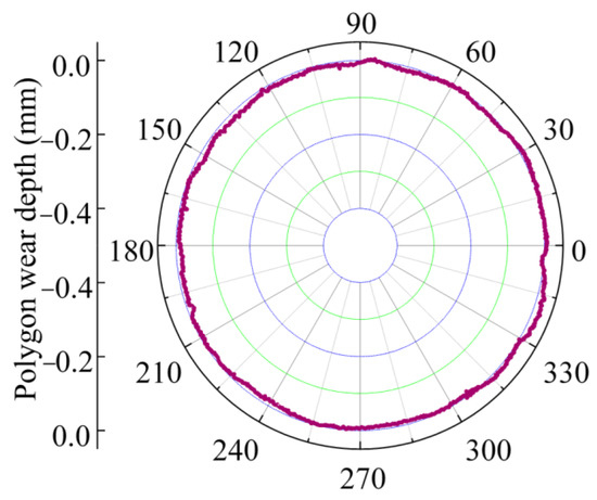
Figure 3.
Wheel polygonal wear.
Subsequently, the turnout rails were evaluated. The phenomenon of rail corrugation, double light bands, light band mutation, and rail fatigue cracks appeared on the right rail surfaces of the turnout in the main line, and the main line left rail and the diverging line rail surfaces were good. The state of the main line right rail surfaces is shown in Figure 4, which shows that the main line right rail profiles deviate from the standard profiles, and the rail surfaces are not smooth. The wheel turning repair cycle had not yet arrived, so the turnout should be ground first to enhance smoothness and maximize the wheel–rail contact relationship.
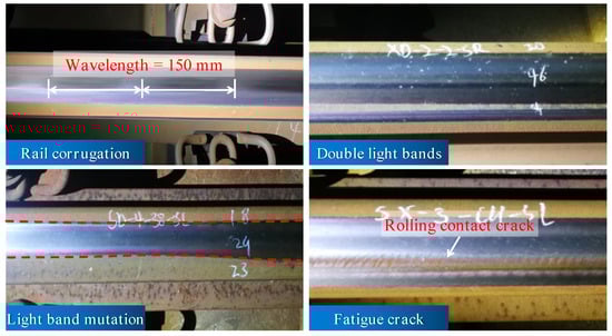
Figure 4.
States of the turnout rail surface defects.
3. Wheel–Rail Contact Geometric Characteristics Analysis
3.1. Rail Profiles before and after Grinding
According to Figure 5, the turnout is divided into five panels: the front panel, the switch panel, the closure panel, the crossing panel, and the rear panel. Contrary to the main line, the rail cross-section of the turnout section varies with distance, and structural characteristics such as rail shape, rail top width, and height are constantly changing, complicating force transmission and boosting vibration-influencing factors. The movable elements and varied railhead portions along the switch rail are two key aspects of the switch panel.
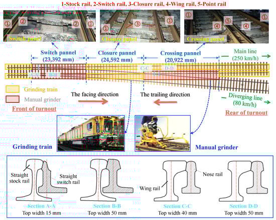
Figure 5.
Schematic diagram of turnout structure.
Due to the over-limit phenomenon of the wheel–rail force and the carbody lateral acceleration when the trains passed through the main line of the turnout, the left rail surfaces of the main line were in good condition, and only the right rail of the main line was ground. The rails of the front panel, the closure panel, and the rear panel were ground by the turnout grinding train. The switch rail and the point rail were weak, so manual grinders were used to grind the switch rail and the point rail based on the standard profile.
As illustrated in Figure 6, the rail profilometer was used to collect the right rail profiles before and after the grinding of each panel of the turnout. The profiles before and after grinding are displayed in Figure 7a–c. The standard deviation in the rail grinding profile rail surface angle at −10°–45° was −0.2 mm–+0.2 mm, determined by the Ministry of Railways of the People’s Republic of China [30], and the rail surface angle distribution is shown in Figure 7d.
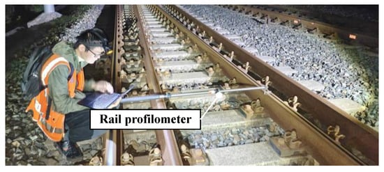
Figure 6.
Collection of rail profiles.
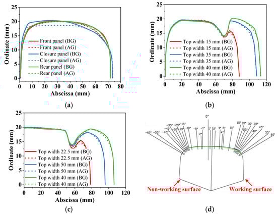
Figure 7.
Turnout rail profiles before and after grinding: (a) front panel, closure panel, and rear panel; (b) switch panel; (c) crossing panel; (d) angle distribution of the rail surface.
3.2. Equivalent Conicity
The concept of equivalent conicity is crucial to understanding vehicle dynamics. While a smaller equivalent conicity can easily result in low-frequency carbody swaying, a larger equivalent conicity can easily cause an unstable running state of the bogie and high-frequency carbody shaking [31]. The wheel–rail contact equivalent conicity values before and after grinding are displayed in Figure 8 in accordance with the UIC519 equivalent conicity calculation method [32]. The equivalent conicity values change significantly when the measured wheel profile makes contact with the turnout’s five-panel rail profile before grinding, and they change slightly after grinding, allowing for better optimization.
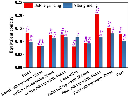
Figure 8.
Equivalent conicity before and after grinding.
3.3. Wheel–Rail Contact Point Distribution
Through the distribution line of wheel–rail contact points, the contact state can be evaluated. In Figure 9, the distribution of wheel–rail contact points is shown both before and after the five turnout panels were ground. The wheel profile shall be the standard profile. The wheel–rail contact points in the turnout’s front and rear panels are dispersed before the rail profiles are ground, but they are concentrated afterward. Before grinding, there are numerous lateral contact points at the working surface of the switch panel and the crossing panel, and after grinding, there are fewer of these points. This effectively prevents the lateral wear of the switch panel and the crossing panel rails.
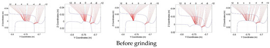
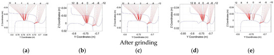
Figure 9.
Turnout wheel−rail contact points distribution before and after grinding: (a) front panel; (b) switch panel; (c) closure panel; (d) crossing panel; (e) rear panel.
The wheel–rail contact points in the closure panel are biased toward the rail non-working surface, but after grinding, they are situated in the center of the rail surface. As a result, rail grinding improves the lateral wear of the switch panel and crossing panel rails while also obviously optimizing the position of the closure panel’s wheel–rail contact.
4. Establishment of Vehicle–Turnout Coupled Dynamic Model
4.1. Vehicle Model
The vehicle with the most severe acceleration exceeding the standard was chosen based on survey results from Section 2, and a corresponding vehicle system dynamic model was created (see Figure 10). One carbody, two bogie frames, eight axle boxes, and four wheelsets make up the dynamic model’s 50 degrees of freedom. Each of these components has six degrees of freedom, with the exception of the axle boxes, which have one rotational degree of freedom with respect to the wheelsets. The primary suspension links the wheelsets to the bogie frames, while the secondary suspension links the carbody to the bogie frames. Nonlinear characteristics like the suspension force element and lateral stopping block are fully taken into account during the modeling process. The pivot joint is simulated by a special force element, and the secondary air spring is simulated by a spring-damping force element. The nonlinear wheel–rail creep characteristics and the nonlinear wheel–rail contact geometric relationship are fully taken into account by the vehicle model.
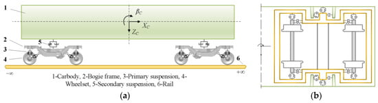
Figure 10.
380A high-speed train vehicle dynamic model: (a) front view; (b) side view.
The vehicle’s dynamic equilibrium equations may be written in the following general form:
where represent the displacement, velocity, and acceleration vectors of the vehicle, respectively. Mv is the mass matrix of the vehicle; Cv and Kv are the damping and stiffness matrices, respectively; Xv is the displacement vector of train components; and Fwr is the vector of the nonlinear wheel–rail forces.
4.2. Turnout Model
As seen in Figure 11a, a model of a high-speed railway turnout was created. In the turnout model, there are numerous rails, and each rail contributes to the system’s vibration to varying degrees. The wheel–rail force is shared by the switch rail, the wing rail, the point rail, and the stock rail. The stock rail and the closure rail are represented by beams with constant cross-sections, while the switch rail, wing rail, and point rail are thought of as Euler beams with variable cross-sections.
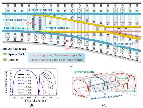
Figure 11.
(a) Dynamic model of a high−speed railway turnout; (b) key sections of switch rail; (c) schematic diagram of key sections fitting method.
The wheel–rail profile measurement equipment is used to measure the important parts of Chinese No. 18 high-speed turnouts as well as their longitudinal locations along the track, as illustrated in Figure 11b. Discrete data from sections with different distances are used to calculate the structural forms of spatial turnouts. The turnout model took into account nonlinear factors like changes in rail profiles, as shown in the fitting processing diagram in Figure 11c.
4.3. Wheel–Rail Contact Model
Piotrowski and Kik [33] proposed a wheel–rail non-elliptical multi-point contact algorithm to calculate creep forces. Let the x-axis direction be the longitudinal direction of wheel–rail contact and the positive direction be the rolling direction of the wheel–rail. The y-axis direction is the lateral direction of wheel–rail contact and is facing the inner side of the rail. The z-axis direction is the normal direction of wheel–rail contact, and the positive direction is the upward direction of the vertical rail surface. The Kik–Piotrowski model solves for the wheel–rail contact patch normal force N and the moment of the normal force M, and the maximum pressure p0 can be calculated as follows:
where δ0 is the amount of penetration at the center of the contact patch; xl(y) are the coordinates of the left edge of the contact area; E, μ are the elastic parameter of the material; and R is the principal radius of curvature of the wheel profile at the point of contact.
After the normal contact force and clearance of wheel–rail contact are obtained, the creep force in the wheel–rail contact area is calculated by the FASTSIM algorithm. The FASTSIM algorithm is a general approach in the sense that its application area is not limited to the elliptical contact, but it can be used for an arbitrary area of contact. In such cases, there is difficulty in computing compliance coefficients since they are only well-defined for elliptic areas of contact. The modified FASTSIM algorithm was therefore used to solve for the tangential forces:
where Ψ is the spin, and ξx, ξy are the longitudinal and lateral creepages. The interpenetration function g(y) is defined to be
where the compliance parameters can be found by equalling the resulting tangent loads to the creep forces obtained according to the linear theory of rolling contact:
where coefficients of creep and spin Cij are tabulated using data of an equivalent elliptic area of contact as parameters.
4.4. Vehicle–Turnout Coupled Dynamic Model
Due to the complex structure and numerous degrees of freedom of the vehicle–turnout coupled system, the vibration equation of the system displays strong nonlinearity, time-varying characteristics, and high equation order. By contrast, it can be seen that the direct integration method is effective in resolving the dynamic response of the vehicle–turnout coupled model. With the direct integration approach, many response values are combined prior to a specific moment in accordance with the presumptive law to obtain the response at that moment. The different variation rules that are taken into consideration form a number of integration methods.
The Park method can be unconditionally stable and has the advantages of high accuracy in low frequency and no overshoot when solving such nonlinear problems. Therefore, the Park method is selected in this paper. The vehicle–turnout coupled dynamics equations for the rigid-flexible system are solved using the Park integral method:
where X is the displacement variable, Δt is the time integration step, and n represents the number of integration steps. The integration steps for both methods take the value 10−4 s.
The coupled dynamic equation of the vehicle–turnout system can be created by combining all of the composition matrices of the dynamic equations from the two models of the vehicle and turnout, which are only connected by the wheel–rail rolling contact model. The dynamics model for the vehicle–turnout coupling created by the dynamics program is shown in Figure 12.
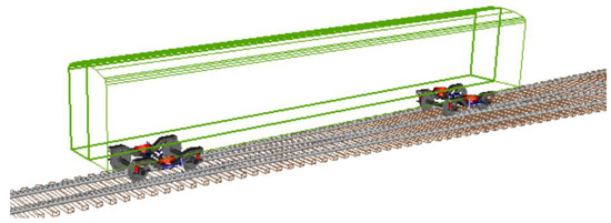
Figure 12.
The vehicle–turnout coupled dynamic model.
5. Dynamic Simulation of High-Speed Train Passing through Turnout
A simulation was performed of the vehicle dynamics characteristics change before and after grinding when a high-speed train travels through the turnout at a speed of 250 km/h, choosing the vehicle with the worst carbody lateral acceleration alarms. We analyzed and compared at the same time the impact of wheel polygonal wear on various aspects of vehicle dynamics.
5.1. Analysis of the Wheel–Rail Force Characteristics
When the train passes through the turnout before and after grinding, Figure 13a depicts how the characteristics of the wheel–rail contact lateral force change. The maximum lateral force, which decreased from 45.97 kN to 32.97 kN—a decrease of 28.28%—occurs when the train passes through the ground turnout without polygonal wear. The maximum lateral force is reduced from 47.55 kN to 38.82 kN, a reduction of 20.46%, when the train passes through the turnout before grinding with polygonal wear, as shown in Figure 13c. The lateral stability and wear of the wheel–rail contact can be improved by grinding.
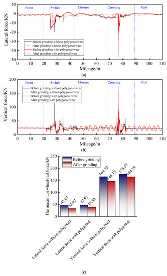
Figure 13.
Changes in the wheel–rail force: (a) lateral; (b) vertical; (c) maximum wheel–rail force.
The variations in the wheel–rail vertical force characteristics when the train passes through the turnout prior to and following grinding are depicted in Figure 13b. The maximum vertical force drops from 164.93 kN to 146.13 kN, or by 11.40%, when the train passes through the ground turnout without polygonal wear. The maximum vertical force that the train can exert when passing through a ground turnout with polygonal wear drops from 175.57 kN to 164.29 kN, a decrease of 6.42%, as shown in Figure 13c. Thus, grinding the turnout rail profiles can improve the wheel–rail vertical force and improve vertical stability and vertical wear.
5.2. Analysis of the Carbody Vibration Acceleration Characteristics
The changes in the carbody lateral acceleration as the train passes through the turnout are depicted in Figure 14a. According to level-one and level-two standards, 0.5–10 Hz band-pass filtering is used to evaluate the carbody lateral acceleration. The level-two alarm (0.90 m/s2) is reached by the maximum carbody lateral acceleration of 1.33 m/s2 when the train passes through the turnout before grinding without polygonal wear [29]. After grinding without polygonal wear, the maximum carbody lateral acceleration as the train passes through the turnout is 0.57 m/s2, which is less than the level-one alarm (0.60 m/s2) and 57.14% less than it was before grinding. The level-two alarm (0.90 m/s2) is reached by the maximum carbody lateral acceleration of 1.34 m/s2 when the train goes through the turnout before grinding with polygonal wear [29]. After grinding without polygonal wear, the maximum carbody lateral acceleration while the train goes through the turnout is 0.57 m/s2, which is less than the level-one alarm (0.60 m/s2) and is acceptable.
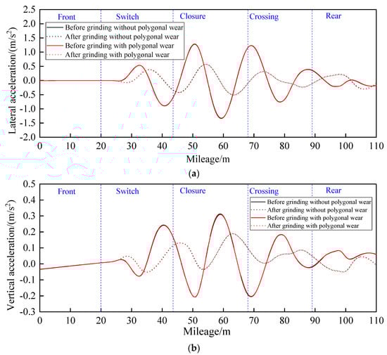
Figure 14.
Changes in the carbody acceleration: (a) lateral; (b) vertical.
Figure 14b depicts how the carbody vertical acceleration changes as the train goes through the turnout. For vertical acceleration, low-pass filtering at 20 Hz is used. When the train passes through the turnout without polygonal wear, the maximum vertical acceleration is decreased from 0.31 m/s2 to 0.19 m/s2, which is 38.71% less than it was before grinding. As the train travels through the turnout with polygonal wear, its maximum vertical acceleration drops from 0.32 m/s2 to 0.19 m/s2, or 40.63%, slower than it did before grinding.
So, whether or not polygonal wear occurs, grinding the turnout rail profile can improve the carbody lateral and vertical acceleration.
In Figure 15, the frequency spectrum of the carbody acceleration as the train travels through the turnout is shown. Whether or not there is polygonal wear, 0–5 Hz is the main frequency of the carbody. When the train passes through the turnout following grinding with polygonal wear, the maximum lateral acceleration amplitude decreases from 0.44 m/s2 to 0.20 m/s2, which is 54.55% lower than that before grinding. After grinding with polygonal wear, the maximum lateral acceleration amplitude is reduced from 0.45 m/s2 to 0.21 m/s2, which is 53.33% less than it was before grinding. When the train passes through the turnout after grinding with polygonal wear, the maximum vertical acceleration amplitude is reduced from 0.083 m/s2 to 0.059 m/s2, which is 28.92% lower than that before grinding. When the train passes through the turnout after grinding with polygonal wear, the maximum vertical acceleration amplitude is dropped from 0.084 m/s2 to 0.059 m/s2, which is 29.76% lower than that before grinding.
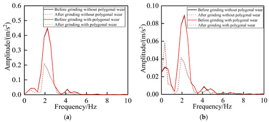
Figure 15.
Changes in the carbody acceleration frequency spectrum: (a) lateral; (b) vertical.
Thus, the main frequency distribution of the carbody acceleration has not changed when the train passes through the ground turnout with or without polygonal wear, but the maximum amplitude values have decreased.
6. Analysis of Measured Data
6.1. Wheel–Rail Force
Between 1 July and 10 July 2022, employees of the railway department utilized the wheel–rail contact dynamic stress tester to monitor the wheel–rail force after grinding. The wheel–rail force was measured as 42 sets of trains passed through the turnout each day. Figure 16 displays the average values of the maximum wheel–rail force experienced by 42 sets of trains per day. When the trains passed through the turnout, there was no phenomenon of wheel–rail force exceeding the limit. Therefore, by grinding the turnout, the phenomenon of the wheel–rail force over-limit was further improved.
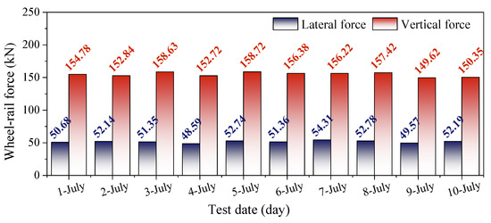
Figure 16.
Wheel–rail force test after grinding.
6.2. Carbody Acceleration
The main job of the comprehensive inspection train is to monitor the safety of the rail. The train is equipped with sensors, which will feed back the data of the rail to the computer for the first time. The changes in the carbody vibration acceleration when the comprehensive inspection train passes through the turnout before and after grinding are shown in Figure 17 and Figure 18.

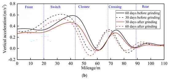
Figure 17.
Changes in the acceleration determined by the comprehensive inspection train: (a) lateral; (b) vertical.
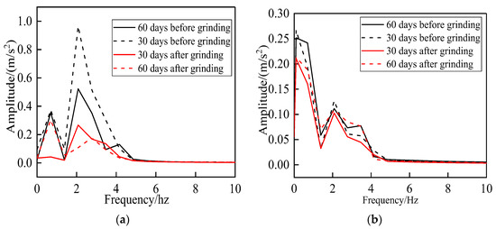
Figure 18.
Changes in the acceleration frequency spectrum determined by the comprehensive inspection train: (a) lateral; (b) vertical.
The carbody lateral and vertical acceleration can be optimized by rail grinding, as demonstrated in Figure 17, where the acceleration after grinding is lower than the acceleration before grinding. The turnout rail profile is different 60 days after grinding compared to 30 days prior to grinding due to the wheel–rail force, as seen by the carbody’s modest increase in lateral and vertical acceleration 60 days after grinding.
Figure 18 shows that the main frequency of the carbody lateral and vertical acceleration is dispersed between 0 Hz and 5 Hz and that the maximum amplitude of these accelerations is lower after grinding than it was before. As seen by the carbody’s small increase in the maximum lateral and vertical acceleration amplitude 60 days after grinding, the turnout rail profile has changed as a result of the wheel–rail force as compared to 30 days previous to grinding.
It is clear that grinding the turnout rail results in improved rail profiles and optimized lateral and vertical acceleration of the carbody, which is consistent with the change trend in the simulation. To prevent the over-limit phenomenon of the carbody acceleration, it is important to periodically grind the rail profile of the turnout when the rail load increases because of the force generated by the wheels against the rail.
From 1 July to 10 July 2022, employees of the railway department tested turnouts using the portable train vibration analyzer. Twenty sets of high-speed trains were examined in all, with two sets per day—one in the morning and one in the afternoon—being evaluated. The lateral acceleration level-one alert occurred eight times when the train went through the turnout, the level-two alarm twice, the level-three alarm once, and there were eight times when there was no lateral acceleration alarm. Given this, grinding the turnout enhanced the lateral stability of the train and the lateral acceleration alarm on the carbody, as shown in Figure 19.
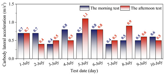
Figure 19.
Carbody lateral acceleration test results after grinding.
7. Conclusions and Future Work
The over-limit problems of the wheel–rail force and the carbody acceleration when multiple sets of trains pass through the high-speed railway turnout were monitored and evaluated using experimental analysis and numerical simulation in this paper. To create a single vehicle–turnout coupled dynamic model for the simulation study, we chose the vehicle with the worst carbody lateral acceleration alarms, set the wheel polygonal wear at the same time, and compared the dynamic response before and after grinding the turnout rail profile. The following are the main findings:
- Following grinding, the wheel–rail contact points, equivalent conicity, and rail damage were improved, and the turnout rail profiles matched the wheel profile well. The simulation findings of the vehicle–turnout coupled dynamic model show that the wheel–rail force and carbody vibration acceleration are significantly reduced when the train goes over the ground turnout, with polygonal worn or not.
- The wheel–rail contact dynamic stress tester, comprehensive inspection train, and portable train vibration analyzer were used to monitor the wheel–rail force and the carbody lateral acceleration before and after the rail grinding. It is evident that following the grinding, the wheel–rail force, the carbody lateral acceleration, and the alarm phenomena of the carbody lateral acceleration were all improved.
- According to the research presented in this paper, rail grinding can improve the wheel–rail force and carbody acceleration, but in order to avoid over-grinding, it is important to grind the rail in strict compliance with the rail’s standard profile. When grinding the front panel, switch panel, closure panel, crossing panel, and rear panel, special attention should be paid to the smoothness of each area and avoid the after-grinding phenomenon of an uneven rail surface. In addition, over time, due to the influence of wheel–rail force, the rail profile will gradually deteriorate following grinding, leading to the issue of over-limited wheel–rail force and carbody acceleration. As a result, it is necessary to routinely grind high-speed railway turnouts.
Author Contributions
Conceptualization, Q.X.; Methodology, Y.Y. and C.C.; Software, Y.Y.; Investigation, D.L. All authors have read and agreed to the published version of the manuscript.
Funding
This research was funded by [National Natural Science Foundation of China, Research on harmonic wear mechanism of high-speed train wheels under spatially coupled vibration behavior of wheel-rail system] grant number [51975210].
Data Availability Statement
No new data were created.
Acknowledgments
The authors wish to thank all the staff members involved in the field test at the China Railway Shanghai Group Co., Ltd., Shanghai, China. This work was supported by the National Natural Science Foundation of China (51975210). Thank you to Sihai Wu from Chengdu Railway Bureau in China for his support in the resource and project management of this paper.
Conflicts of Interest
The authors declare that they have no known competing financial interest or personal relationships that could have appeared to influence the work reported in this paper.
References
- Kisilowski, J.; Kowalik, R. Method for Determining the Susceptibility of the Track. Appl. Sci. 2022, 12, 12534. [Google Scholar] [CrossRef]
- Wang, P.; Sun, Z.; Mu, Z.; Zhao, Z.; Wang, S. Experimental Research on the Load Transfer Mechanism of Tie Plates for 400 km/h High-Speed Turnouts. Appl. Sci. 2022, 12, 9988. [Google Scholar] [CrossRef]
- Chen, R.; Wang, P.; Song, Y. Wheel/Rail Contact Geometry of Different Wheel Tread Profile in High-Speed Railway Turnout. Adv. Mater. Res. 2011, 255–260, 3988–3992. [Google Scholar] [CrossRef]
- Nielsen, J.C.O.; Pålsson, B.A.; Torstensson, P.T. Switch panel design based on simulation of accumulated rail damage in a railway turnout. Wear 2016, 366–367, 241–248. [Google Scholar] [CrossRef]
- Zeng, X.; Lai, J.; Wu, H. Hunting stability of high-speed railway vehicles under steady aerodynamic loads. Int. J. Struct. Stab. Dyn. 2018, 18, 1850093. [Google Scholar] [CrossRef]
- Yang, X.; Qu, C.; Yi, T.; Li, H.; Liu, H. Dynamic Performance Analysis of a High-Speed Railway Bridge Under Train Actions Using Operational Modal Parameters. Int. J. Struct. Stab. Dyn. 2021, 21, 2140007. [Google Scholar] [CrossRef]
- Taubert, M. High-speed grinding-rail maintenance within a timetable. Railw. Track Struct. 2011, 107, 49–50. [Google Scholar]
- Magel, E.E.; Kalousek, J. The application of contact mechanics to rail profile design and rail grinding. Wear 2002, 253, 308–316. [Google Scholar] [CrossRef]
- Lin, B.; Zhou, K.; Guo, J.; Liu, Q.; Wang, W. Influence of grinding parameters on surface temperature and burn behaviors of grinding rail. Tribol. Int. 2018, 122, 151–162. [Google Scholar] [CrossRef]
- Steenbergen, M. Rolling contact fatigue in relation to rail grinding. Wear 2016, 356–357, 110–121. [Google Scholar] [CrossRef]
- Pletz, M.; Daves, W.; Ossberger, H. A wheel passing a crossing nose: Dynamic analysis under high axle loads using finite element modelling. Proc. Inst. Mech. Eng. Part F J. Rail Rapid Transit 2012, 226, 603–611. [Google Scholar] [CrossRef]
- Xu, J.; Wang, P.; Ma, X.; Yuan, G.; Rong, C. Stiffness characteristics of high-speed railway turnout and the effect on the dynamic train-turnout interaction. Shock Vib. 2016, 2016, 1258681. [Google Scholar] [CrossRef]
- Xu, J.; Wang, P.; Ma, X.; Xiao, J.; Chen, R. Comparison of calculation methods for wheel-switch rail normal and tangential contact. Proc. Inst. Mech. Eng. Part F J. Rail Rapid Transit 2016, 231, 148–161. [Google Scholar] [CrossRef]
- Kassa, E.; Nielsen, J.C.O. Dynamic train-turnout interaction in an extended frequency range using a detailed model of track dynamics. J. Sound Vib. 2009, 320, 893–914. [Google Scholar] [CrossRef]
- Burgelman, N.; Li, Z.; Dollevoet, R. A new rolling contact method applied to conformal contact and the train-turnout interaction. Wear 2014, 321, 94–105. [Google Scholar] [CrossRef]
- Sebes, M.; Ayasse, J.B.; Chollet, H.; Pouligny, P.; Pirat, B. Application of a semi-Hertzian method to the simulation of vehicles in high-speed switches. Veh. Syst. Dyn. 2006, 44, 341–348. [Google Scholar] [CrossRef]
- Ma, X.; Wang, P.; Xu, J.; Rong, C. Parameters studies on surface initiated rolling contact fatigue of turnout rails by three-level unreplicated saturated factorial design. Appl. Sci. 2018, 8, 461. [Google Scholar] [CrossRef]
- Sugiyama, H.; Tanii, Y.; Matsumura, R. Analysis of Wheel/Rail Contact Geometry on Railroad Turnout Using Longitudinal Interpolation of Rail Profiles. J. Comput. Nonlinear Dyn. 2011, 6, 024501. [Google Scholar] [CrossRef]
- Wang, P.; Xu, J.; Xie, K.; Chen, R. Numerical simulation of rail profiles evolution in the switch panel of a railway turnout. Wear 2016, 366–367, 105–115. [Google Scholar] [CrossRef]
- Choi, H.; Lee, D.; Song, C.; Lee, J. Optimization of rail profile to reduce wear on curved track. Int. J. Precis. Eng. Manuf. 2013, 14, 619–625. [Google Scholar] [CrossRef]
- Xu, K.; Feng, Z.; Wu, H.; Xu, D.; Li, F.; Shao, C. Optimal profile design for rail grinding based on wheel–rail contact, stability, and wear development in high-speed electric multiple units. Proc. Inst. Mech. Eng. Part F J. Rail Rapid Transit 2020, 234, 666–677. [Google Scholar] [CrossRef]
- Uhlmann, E.; Lypovka, P.; Hochschild, L.; Schröer, N. Influence of rail grinding process parameters on rail surface roughness and surface layer hardness. Wear 2016, 366–367, 287–293. [Google Scholar] [CrossRef]
- Satoh, Y.; Iwafuchi, K. Effect of rail grinding on rolling contact fatigue in railway rail used in conventional line in Japan. Wear 2008, 265, 1342–1348. [Google Scholar] [CrossRef]
- Tyfour, W.R. Predicting the effect of grinding corrugated rail surface on the wear behavior of pearlitic rail steel. Tribol. Lett. 2008, 29, 229–234. [Google Scholar] [CrossRef]
- Real, J.I.; Zamorano, C.; Velarte, J.L.; Blanco, A.E. Development of a vehicle–track interaction model to predict the vibratory benefits of rail grinding in the time domain. J. Mod. Transp. 2015, 23, 189–201. [Google Scholar] [CrossRef]
- Wang, R.; Zhou, K.; Yang, J.; Ding, H.; Liu, Q. Effects of abrasive material and hardness of grinding wheel on rail grinding behaviors. Wear 2020, 454–455, 203332. [Google Scholar] [CrossRef]
- Zhou, K.; Ding, H.; Wang, R.; Yang, J.; Wang, W. Experimental investigation on material removal mechanism during rail grinding at different forward speeds. Tribol. Int. 2019, 143, 106040. [Google Scholar] [CrossRef]
- Ministry of Railways of the People’s Republic of China. Testing of China Railway High-Speed Electic Multiple Units on Completion of Construction; Ministry of Railways of the People’s Republic of China: Beijing, China, 2008. (In Chinese) [Google Scholar]
- Ministry of Railways of the People’s Republic of China. Maintenance Rules for Ballasted Track Lines of High-Speed Railways; Ministry of Railways of the People’s Republic of China: Beijing, China, 2021. (In Chinese) [Google Scholar]
- Ministry of Railways of the People’s Republic of China. Measures for the Administration of High-Speed Railway Rail Grinding; Ministry of Railways of the People’s Republic of China: Beijing, China, 2008. (In Chinese) [Google Scholar]
- Gan, F.; Dai, H.; Gao, H.; Chi, M. Wheel–rail wear progression of high speed train with type S1002CN wheel treads. Wear 2015, 328–329, 569–581. [Google Scholar] [CrossRef]
- International Union of Railways. UIC519, Method for Determining the Equivalent Conicity; International Union of Railways: Paris, France, 2004; pp. 33–37. [Google Scholar]
- Piotrowski, J.; Kik, W. A simplified model of wheel/rail contact mechanics for non-Hertzian problems and its application in rail vehicle dynamic simulations. Veh. Syst. Dyn. 2008, 46, 27–48. [Google Scholar] [CrossRef]


Disclaimer/Publisher’s Note: The statements, opinions and data contained in all publications are solely those of the individual author(s) and contributor(s) and not of MDPI and/or the editor(s). MDPI and/or the editor(s) disclaim responsibility for any injury to people or property resulting from any ideas, methods, instructions or products referred to in the content. |
© 2023 by the authors. Licensee MDPI, Basel, Switzerland. This article is an open access article distributed under the terms and conditions of the Creative Commons Attribution (CC BY) license (https://creativecommons.org/licenses/by/4.0/).