Abstract
Methodologies are developed for analyzing failure initiation and crack propagation in highly heterogeneous concrete mesostructures. Efficient algorithms are proposed in Python to generate and pack geometric features into a continuous phase. The continuous phase represents the mortar matrix, while the aggregates and voids of different sizes represent the geometric features randomly distributed within the matrix. The cohesive zone model (CZM) is utilized to investigate failure initiation and crack propagation in mesoscale concrete specimens. Two-dimensional zero-thickness cohesive interface elements (CIEs) are generated at different phases of the concrete mesostructure: within the mortar matrix, aggregates, and at the interfacial transition zone (ITZ). Different traction–separation laws (TSL) are assigned to different phases to simulate potential crack paths in different regions of the mesoscale concrete specimen. The mesoscale finite element simulations are verified using experimental results from the literature, with a focus on implementing mixed-mode fracture and calibrating its corresponding parameters with respect to the experimental data. In addition, the current study addresses the limited exploration of void effects in mesoscale concrete simulations. By investigating voids of diverse sizes and volume fractions, this research sheds light on their influence on the mechanical behavior of concrete materials. The algorithms for generating cohesive interface elements and concrete microstructures are described in detail and can be easily extended to more complex states. This methodology provides an effective tool for the mesostructural optimization of concrete materials, considering specific strength and toughness requirements.
1. Introduction
Concrete is a vital building material that undergoes various types of loads, notably tensile loads during events such as earthquakes or explosions [1]. Despite being commonly treated as a homogeneous material in structural design, concrete exhibits intricate and nonlinear behavior even under simple loading conditions. This complexity arises from its highly heterogeneous internal material structure, with microcracks forming, propagating, accumulating, and coalescing [2,3]. Moreover, the structural behavior of concrete is profoundly influenced not only by the morphological properties of aggregate particles (e.g., size, shape, volume fraction, spatial distribution) but also by the material properties of each constituent component. Consequently, concrete failure represents a multiscale phenomenon, necessitating a comprehensive consideration of the various material properties of its internal structure [2].
Understanding the mesoscale fracture behavior of concrete materials has significant implications for macroscopic structural performance. Mesoscale simulations reveal crack propagation patterns and interactions, enabling the design of more robust structures with improved resistance to failure. This knowledge enhances load-carrying capacity and strength by optimizing concrete mix designs and reinforcing vulnerable areas. The insights also guide material selection and optimization, evaluating different compositions to meet specific performance requirements. Furthermore, understanding mesoscale fracture behavior empowers innovative design concepts, tailoring microstructural features to enhance crack control, strain capacity, and load redistribution. These applications advance concrete engineering practices, ensuring safer and more durable structures in various practical engineering scenarios.
Concrete is a complex composite material analyzed at multiple scales: nano, micro, and meso. The mesoscale, the largest length scale, explicitly reveals concrete’s heterogeneity. Here, concrete comprises coarse aggregates surrounded by a mortar matrix, cement paste, voids, and the aggregate–mortar interface known as the interface transition zone (ITZ). Morphological and material properties of aggregates and phases at this scale significantly impact concrete’s observable behavior at the structural level.
In continuum mesoscale modeling of concrete geometries, two main approaches are commonly used. The first approach is the digital-image-based method, where concrete specimens are captured using image processing technology to generate accurate mesostructures [4]. However, this method can be time consuming, expensive, and may result in overlapping aggregates if the boundaries are not properly identified [5]. The second approach is parameterization modeling [3], where concrete mesostructures are generated using algorithms that represent concrete’s geometry parametrically. This approach allows for generating various shapes, such as spherical, ellipsoidal, or polyhedral, randomly placed within the mortar matrix [6,7,8]. While many publications use simpler shapes such as spheres or ellipsoids [3,9,10,11,12], others employ polygonal shapes to achieve a more realistic representation of aggregates [13,14]. It is worth noting that in many mesostructure models, only the aggregates are randomly distributed within the mortar matrix, neglecting the contribution of voids. However, X-ray tomographic analysis reveals the existence of voids in concrete specimens. Therefore, developing algorithms that account for the contribution of voids in the mesostructure of concrete is crucial.
As mentioned, the observable behavior of concrete at the structural level is influenced by the morphological and material properties of aggregates and phases at the mesoscale length scale. To gain a deeper understanding of concrete’s macroscale behavior, a comprehensive numerical model should consider these properties, as well as the local failure mechanisms within the mesostructure. Numerous numerical models have been developed for mesoscale concrete analysis, each with distinct strengths and limitations. The lattice model treats concrete as a discrete system, allowing simulation of failure mechanisms within different phases. Although the model is simple and it is easy to assign material properties, it struggles with complex geometries and continuum representation [12,15,16]. The particle model offers computational efficiency, but precise calibration of numerical parameters is time consuming, limiting accuracy at larger scales [17,18,19,20]. The distinct finite element method (DEM) analyzes concrete as interacting particles, effective for granular materials but computationally intensive and challenging for highly dense systems [21,22]. The boundary finite element method (BEM) excels in structural analysis with domain boundary focus, but faces difficulties in scenarios where interior domain information is crucial [23]. The combined finite–discrete element method (FDEM) effectively captures elastic deformation and post-failure behavior, but implementation complexities arise due to combining fundamentally different methodologies [24,25]. Finally, the continuum finite element approach with explicit representation of the mesostructure is commonly used for concrete analysis [2,14,26,27,28]. Cohesive zone modeling (CZM) is increasingly popular for failure and fracture analysis of concrete and similar materials due to its straightforward formulation and implementation, involving cohesive elements inserted at solid interfaces [29,30,31,32]. The application of CIEs within the CZM to simulate fracture behavior has great potential for the realistic simulation of crack initiation and propagation in brittle and semi-brittle materials. Interested readers are also referred to some recent publications in the field of CZM-based FE model simulation of concrete materials using CIEs [33,34,35,36,37,38,39]. Two common points in these publications are, first, the potential of CZM to provide realistic simulation outputs that resemble experimental ones, and second, the performance of parametric studies that pave the way for the development of concrete materials with specific properties.
The objective of this research is to address the limitations of current methods used to simulate fracture in brittle materials, particularly in concrete. A significant limitation in the existing literature is the predominant use of single-mode fracture simulations for concrete materials at the mesoscale, neglecting the dependence of fracture behavior on the specific type of fracture. Additionally, many finite element implementations of concrete materials at the mesoscale assume that shear fracture energy is equal to normal fracture energy in the pre-processing step, overlooking the significant heterogeneity in concrete materials [32]. This work overcomes this limitation by considering mixed fractures calibrated against experimental data, providing a more accurate representation of concrete material behavior under mixed fracture conditions.
Moreover, there is a notable gap in the field of mesoscale simulations for concrete materials concerning the generation of particulate concrete microstructures with randomly distributed aggregates of various shapes, as well as voids of different sizes and shapes, and the creation and insertion of cohesive interface elements for three-phase materials such as concrete. This work pioneers a fully described, detailed approach to generate microstructures and insert cohesive interface elements for concrete at the mesoscale level, as well as other composite materials with varying numbers of phases. To the best of the authors’ knowledge, existing codes or literature lack applicability for three-phase materials, especially when dealing with varying void sizes and shapes. The proposed algorithms significantly contribute to enabling the creation of cohesive interface elements applicable to diverse element types in both two and three dimensions, accommodating any given microstructure.
Furthermore, this work develops a holistic method for analyzing the effects of morphological mesostructural properties on the structural response of concrete materials using cohesive zone modeling (CZM)-based finite element (FE) models. In this paper, a two-dimensional (2D) simulation of crack initiation and propagation is performed using the continuum FEM approach with the implementation of cohesive interface elements (CIEs). Additionally, the presence of voids in the concrete microstructure significantly influences its mechanical behavior, contributing to increased cracking, reduced durability, and diminished strength and stiffness. Thus, two essential tools are developed: the generation of a 2D concrete mesostructure and the insertion of CIEs within the interface of solid elements after discretizing the concrete mesostructure generated in the first step.
Firstly, an in-house developed Python code CMG (concrete microstructure generator) generates the mesostructure of concrete with different aggregate shapes and circular voids. CMG is capable of generating randomly distributed and varying size circular, elliptical, and polyhedral aggregates and circular voids within the mortar matrix. Second, CIEs are inserted at the interfaces of the continuum elements constituting the mortar matrix, the aggregates, and the ITZ zone. This task is performed by a self-developed Python code CIEsIn (cohesive interface element insertion). It should be mentioned that the interface element insertion is performed before the finite element simulations. Finally, the performance of the developed code is shown using numerical examples.
The outline of this paper is as follows: Section 2 comprehensively describes the procedure for generating concrete mesostructures with different aggregate shapes. Section 3 details the algorithms for the automatic generation and insertion of CIEs into an initial FE mesh. Section 4 explains the details of the numerical model, such as material properties, element types, and boundary conditions. In Section 5, the morphological parameter studies are performed, and the main results are given in the Conclusions section.
2. Two-Dimensional Heterogeneous Mesostructures of Concrete
Concrete is a heterogeneous material whose nonlinear behavior can be attributed to the formation and coalescence of microcracks. The formation and propagation of microcracks is closely related to the mesostructural features of concrete. The mesostructure of concrete can be characterized by three important features: the shape of the aggregate, the size distribution of the aggregate, and its spatial position and orientation within the concrete specimen. These mesostructural features determine the structure of the ITZ zone and consequently, the macroscopic fracture energy [40]. Therefore, an accurate illustration of the heterogeneous material mesostructure of concrete is a crucial issue in realistic mesoscale numerical models of concrete materials. In addition, certain statistical properties of concrete, such as the size distribution of aggregates, must be realized in mesoscale numerical models.
In this section, algorithms in the self-developed Python code CMG are described in detail. The CMG can generate a 2D concrete mesostructure with randomly distributed circular, elliptical, and arbitrary polygonal aggregates with intersection and overlap detection control. Depending on the type of aggregates used in the concrete sample, they can have different shapes. For example, ceramic particles used in concrete have an ellipsoidal shape, foam particles in concrete are modeled as spheres, and crushed stones and gravels with relatively large edges are modeled as polyhedrons. In order to create a realistic mesostructure of concrete, there are several methods and procedures. Details of the procedure to generate the particle aggregates can be found in the literature, e.g., [14,28,41,42,43]. In this study, the coarse aggregates are considered within the volume of the concrete specimen. However, the algorithms developed in Python can also be used to study fine aggregates in concrete.
2.1. Aggregate Size Distribution
The aggregates used in concrete can be divided into two different groups, namely, fine and coarse aggregates. Fine aggregates consist mainly of sands or crushed stones with a diameter of less than 4.75 mm, and all particles with a diameter of more than 4.75 mm are considered coarse aggregates in concrete samples [44]. In normal concrete, the coarse aggregates account for about 40% to 50% of the concrete volume [27]. Many researchers use the Fuller curve as a grading curve to illustrate the size distribution of aggregate in a mesoscale numerical model for concrete. The Fuller curve illustrates the gradation of aggregate in the concrete sample, and its implementation would result in a concrete mix with optimum aggregate compaction and strength. The Fuller curve can be expressed as follows:
where represents the cumulative percentage of aggregates that is below the size of the aperture diameter of a sieve (d), is the maximum aggregate particle size, and n, which is a constant parameter, is the exponent of the equation and varies from to .
To obtain the volumetric ratio of coarse aggregates in a concrete sample, it is possible to divide the total weight of coarse aggregates per volume of concrete by the density of the aggregate particles. This can be expressed as [14]:
where is the total aggregate’s volume fraction, represents the total weight of aggregate particles in the concrete specimen, is the specific weight, and V is the total volume of the concrete specimen. To numerically implement the Fuller curve from Equation (1), it can be divided into any number of segments, and for each segment the volume fraction of aggregates can be calculated as follows [27]:
where represents the volume percentage of aggregates within the discretized aggregate size range and and denote the maximum and minimum sizes of the aggregate particles, respectively. The reference case of concrete considered in this paper is a sample with medium and coarse aggregates varying in size from 3.5 mm to 15 mm. For the numerical implementation of the Fuller curve, the aggregates are divided into five aggregate segments, namely, [] mm, [] mm, [] mm, [] mm, and [] mm. To calculate the cumulative volume fraction of each aggregate, n is assumed to be 0.5, and the target aggregate volume ratio in the 2D mesoscale model of concrete is assumed to be 50%. Table 1 illustrates the aggregate size distribution of coarse aggregate used in this study. According to Table 1, aggregates smaller than 3.5 mm are not considered in the model and form the mortar together with the cement matrix. Since small elements are required to discretize the fine aggregates, eliminating them does not require a large number of elements to discretize the entire mesoscale model, and consequently avoids high computational costs. It should be mentioned that there is no restriction on the number of aggregate size intervals. Furthermore, the implementation of the segmented size distribution of aggregates in the developed algorithm distributes the aggregate sizes uniformly within the upper and lower bounds of each interval segment. More precisely, the aggregate size is increased uniformly within each gradation segment, resulting in a mesoscale model where the actual Fuller curve is perfectly approximated. In this study, circular, elliptical, and polygonal aggregates are used to model the mesostructure of concrete in 2D. The equations used to generate the different aggregate shapes are described in detail below.

Table 1.
Cumulative volume percentage of coarse aggregates and volume ratio of aggregate particles within the discretized size range.
2.1.1. Random Circular and Ellipsoidal Aggregates
To generate a circular aggregate particle, a Cartesian X–Y coordinate system is used as follows:
where and represent the coordinates of the center of the circle and r is the radius of the circle. The radius of each circle is calculated as:
where and represent the minimum and maximum diameter of aggregate particles in the segmented grading curve, respectively (see Table 1), and is a random number that is uniformly distributed between 0 and 1.
To generate randomly rotated elliptical aggregate particles with various sizes, the following equations are implemented in the Cartesian coordinate system as follows:
where and are the center of an ellipse and a, b, and c are components that are calculated as follows:
where is the rotation angle chosen randomly between −90 and 90 degrees. and are called the semi-major and semi-minor axes, respectively. and can be calculated as follows:
where is a random number that is uniformly distributed between 0 and 1 and is a random number between the aspect ratio range. In this work, the aspect ratio range is between and .
2.1.2. Random Polygon Aggregates
The concept of the convex hull algorithm is used to generate polygon aggregate particles. The convex hull of a set of random points represents a polygon that encloses all of these points such that its vertices maximize the area of the polygon while minimizing its perimeter. Figure 1b illustrates the convex hull of a set of points randomly distributed in the XY plane. To prescribe a polygon aggregate in 2D, an incremental polygon of a circle is utilized. An incremental polygon of a circle is a polygon whose vertices all intersect with the circle. The higher the number of vertices of a polygon, the better the approximation of the circle by the polygon. The creation of a polygon aggregate starts with the selection of random points on the circumference of a circle. The set of random points can be determined using the following equations:
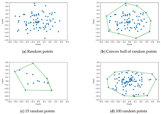
Figure 1.
The generation of a polygon inclusion is achieved by implementing the convex hull of a set of random points (b). Depending on the number of selected random points, different shapes of polygon aggregates can be generated (c,d).
In Equation (12), variables r and are random numbers. r is calculated using Equation (5) and is obtained as:
where is a random number between 0 and 1. After selecting a set of random points by implementing Equation (12) to Equation (13), the polyhedron aggregate is generated using the convex hull algorithm developed in Python. In the developed code, the method Jarvis march or gift wrapping [45] is used to calculate the convex hull of a set of random points.
As mentioned earlier, to generate a polygon aggregate, a set of random points must be selected from the vertices of an incremental polygon of a circle. Depending on the number of points selected, polygon aggregates with different configurations can be generated. For example, a high number of points would result in gravel aggregates with smooth edges, while a lower number of points would result in aggregates with distinctly visible angular edges. Figure 1c,d show the effect of the number of points selected on the shape of the polygon aggregate particles.
2.2. Aggregate Packing
The next step after the aggregates are generated is their random distribution within the concrete mesoscale specimen. This process is called the placing process. During placement, three important conditions must be met. These conditions are as follows:
- The aggregate must be placed completely within the boundaries of the concrete specimen without crossing them.
- The newly placed aggregate must not overlap with already placed aggregates.
- A small gap should be left between each two positioned aggregates to create a mortar layer thickness between the aggregates.
To meet all of the above conditions, the following intersection checks must be performed:
- Check 1The first condition is satisfied if all vertices of the generated aggregate lie within the boundary of the mesoscale concrete specimen. For the transfer of the generated aggregate within the boundaries of the concrete specimen, a translation vector is generated by extracting a random coordinate whose origin is at the center of the coordinate system. The chosen random value must be within the main frame of the mesoscale specimen. After the translation process, the coordinates of all vertices are compared with the main frame coordinates of the concrete, and if an overlap is detected, a new translation vector is built until the first condition is satisfied.
After the first condition is satisfied, the overlap of the newly placed aggregate with already placed aggregate particles is checked. For circular and elliptical aggregates, this task is simply solved by implementing the corresponding construction Equations (see Equations (4) and (6)). For this purpose, two main intersection processes must be performed as follows:
- Check 2 and Check 3Intersection check 2 and check 3 are carried out simultaneously. Assume that the constructive Equation of the newly placed aggregate particle is denoted by . To perform intersection check 2, the value of is calculated using the constructive vertices of each already placed aggregate. If the value of is equal to or smaller than one, this indicates that at least one already placed aggregate has an intersection with the new aggregate and the newly placed aggregate must be removed from the main frame. In addition, intersection check 3 is performed automatically by setting the minimum value of in intersection check 2 to 1.2. In this way, a small gap between the aggregate particles is realized. Therefore, the small gap condition is simultaneously fulfilled in this step.
- Check 4The fulfillment of intersection check 2 and check 3 is a necessary condition. However, it is not sufficient, because in the developed Python code, the placement process always starts with the aggregates with larger sizes and it may happen that the newly placed aggregate is exactly inside the already placed aggregate without intersecting its boundaries. This condition cannot be detected by intersection check 2. To solve this problem, the constructive Equation of the already placed aggregate is established and its value is checked with the vertices of the newly placed aggregate. In this condition, if the result of the constructive equation becomes less than one, it shows that the smaller newly placed aggregate is exactly inside a larger aggregate and this aggregate must be removed from the main frame.
The algorithms developed for this study automatically determine the morphology of the mortar layer based on the inserted aggregate particles, thereby providing control over the minimum thickness between two adjacent aggregates. When an aggregate particle is introduced, its contributing nodes are factored into the equations of previously positioned aggregates. Intersection with existing aggregates is indicated by equation outcomes less than 1, necessitating the removal of the newly inserted aggregate. Conversely, an outcome greater than 1 confirms non-intersection. However, values very close to 1 can lead to negligible separation between aggregates, resulting in exceedingly thin mortar layers that could cause issues in numerical simulations, especially during model discretization. To circumvent this, a threshold value of 1.2 has been instituted. If the equations’ outcomes for previously placed aggregates fall below this threshold, the newly introduced aggregate is eliminated, thus ensuring a minimum interspace between closely positioned aggregates and preventing unreasonably thin mortar layers.
It is worth mentioning that all intersection checks must be performed for polygonal aggregates as well. However, this is not possible when using the constructive equation approach. To overcome this problem, a Python library called shapely is implemented in the Python code to automatically identify the intersection of polygonal aggregates. Since in this work the verification processes are performed in 2D, the computational cost is not a major problem. However, the developed Python code efficiently generates concrete mesostructures with up to 50% aggregate volume fraction. For cases with more than 50% aggregate volume fraction, the computational cost increases significantly. This is due to the higher number of intersection checks required with already placed aggregate particles, and the likelihood of finding empty spaces within the mortar matrix becomes low. In the 3D case, where the computational cost could be drastically high, it is recommended to perform the intersection check with the neighboring aggregates that have a high probability of intersecting with the new aggregate. It is also possible to apply random rotation and displacement to increase the probability of successfully placing new aggregate particles. In this condition, new algorithms must be developed to identify the aggregate particles near the new aggregate and apply random rotation and displacement. Figure 2 shows the flowchart of the take-place process implemented in this work.
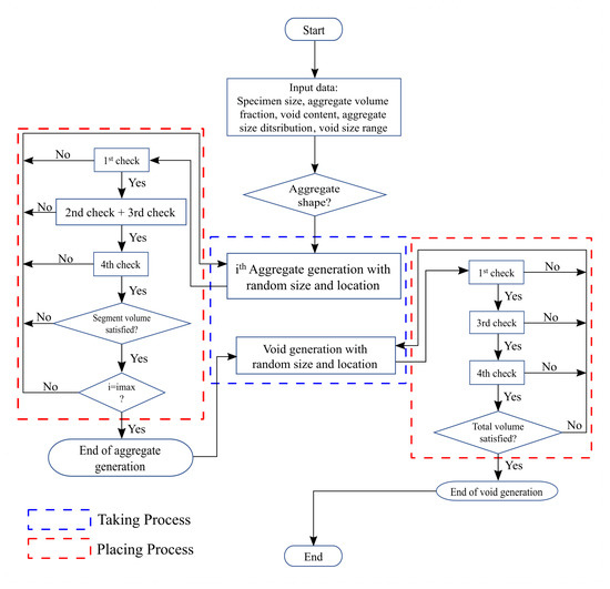
Figure 2.
Flowchart to generate aggregates and voids.
3. Automatic Generation of Cohesive Elements
To the authors’ knowledge, direct implementation of cohesive interface elements into an existing finite element mesh is not possible in Abaqus/CAE, so a Python code is developed to solve this issue. The Python code reads an FE mesh file generated by Abaqus and then generates 2D cohesive interface elements between the interfaces of two adjacent solid elements. Figure 3a shows a 2D four-node cohesive interface element. The code starts by reading the FE mesh file containing the data of the nodes and elements. Then, a node connectivity list is created for each node. In this context, the node connectivity list illustrates a set of elements that surround a specific node. Then, the mesh is modified by duplicating the nodes followed by generating element connectivity lists of cohesive elements. In the following, the algorithms for generating cohesive elements in a particulate composite with three different phases are described in detail. For this purpose, a mesh of triangular elements is considered, where each solid element has three nodes. The steps required to generate cohesive elements are described below. In addition, Algorithm 1 briefly summarizes the procedures for generating cohesive elements.
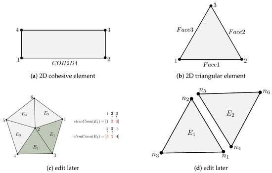
Figure 3.
Four Figures with Subtitles.
- Step 1: InitializationThe initial FE mesh file generated by Abaqus/CAE is imported into the Python code, and by processing the node and element data, three main data structures are generated. A unique specific ID number is assigned to each node and element in the first and second data structures, and the corresponding coordinates and element connectivity list are stored, respectively. It is worth mentioning that the assigned ID numbers are positive integers. The element connectivity list represents all nodes that constitute an element. As illustrated in Figure 3b, the element connectivity list of a triangular element is [1-2-3]. Element sets are stored in the third data structure, and the elements in each set are assigned a specific material ID. In this context, element sets, which are automatically written to the original FE mesh file, represent a specific region of discretized geometry. The elements forming the mortar matrix are labeled with the material ID equal to zero, whereas the elements constituting the aggregates would have different material ID numbers. The material ID numbers for aggregates are positive integers, and the corresponding value for each aggregate depends on the name of the aggregate’s element set in the original FE mesh file. For instance, if the name of the element set of a particular aggregate in the initial FE mesh file is one, the elements that constitute that aggregate will be labeled with a material ID of one. Material IDs enable the generation of cohesive interface elements at different phases of the concrete mesostructure.
- Step 2: Construction of node connectivity listA data structure called the node connectivity list (ndConnL) is created that stores the element IDs of all elements that contain a particular node. The node connectivity list of each node is determined by traversing the element connectivity list of all elements so that all possible elements containing a given node in their element connectivity list are identified.
- Step 3: Identification of ITZ nodesThe nodes located at the interface of the aggregates and mortar matrix are identified. For this purpose, the node connectivity list of each node is called from the corresponding data structure in Python, and in the second step, the corresponding material ID of each element in the node connectivity list is determined. Then, the extracted material IDs are compared with each other. If the material IDs are not unique, then the corresponding node is in the ITZ zone.
- Step 4: Identification of adjacent elementsIn this step, every two neighboring elements that share a common face will be identified. To this end, the node connectivity list of each node is called. Then, an extraction of the element connectivity lists of all elements contained in the node connectivity list is performed. A comparison is made between all element connectivity vectors, and when the number of common nodes between two elements reaches two, it means that these two elements are adjacent. This process is performed for all elements, and the element IDs of the adjacent elements are stored in a separate data structure.
- Step 5: Assigning face typeFace type is assigned to each of the two adjacent elements identified in the previous step, and the corresponding face type of each element is stored in a separate data structure. Figure 3b illustrates a two-dimensional triangular element with its corresponding node numbering. As can be seen, a 2D triangular element has three faces consisting of the segments defined by the nodes [1–2] for face 1, nodes [2–3] for face 2, and nodes [3–1] for face 3. To assign the face type to each element, first, the element connectivity list of each two adjacent elements is extracted. Then, new numeric labels are assigned to the components of the element connectivity list. These new numerical labels are integer positive numbers ranging between 1 and 3. As mentioned earlier, adjacent elements have two common nodes; in this state, the corresponding new numerical labels of the common nodes are extracted for each adjacent element. Based on the new numerical labels of the common nodes, the face type is identified and assigned to each element. As Figure 3c illustrates, nodes [2–3] represent the common interface between elements and . With respect to the corresponding new numerical labels of the common nodes, Face 2 is assigned to element and face 1 is assigned to element .
- Step 6: Multiplication of cohesive nodesThose nodes that are located at the interface of two adjacent elements are multiplied, and in this way cohesive nodes are generated. It is worth mentioning that if the node connectivity list has n members, n − 1 new nodes are generated and the original node is always assigned to an element with the smallest element ID in the node connectivity list. After this operation, interface nodes do not exist anymore and each created node is allocated to a different element. Therefore, it is crucial to update the element connectivity list of each element after the generation of cohesive nodes.
- Step 7: Generation of cohesive elementsFor this purpose, the updated element connectivity list and face type of each two adjacent elements are retrieved, and with these data at hand, the element connectivity list of a four-node cohesive element (COH2D4) is written. The traction–separation law (TSL) is implemented as the material property of cohesive elements which is based on the deformation vector of the nodes. As shown in Figure 3d, the first two nodes (, ) belong to the bulk element and the other two nodes (, ) belong to the to the bulk element . When there is no deformation, node coincides with , and node coincides with node . The distance between these nodes determines the interface separation. Since the finite element solver can distinguish between the opening and closing of the cohesive element with respect to its element connectivity list, its node arrangement must be written correctly in a counterclockwise manner. The triangular elements can have any orientation in space, but the node numbering is always as illustrated in Figure 3b. It is worth mentioning that the face type of the adjacent elements helps to write the element connectivity list of the cohesive elements in a counterclockwise fashion, which leads to a correct distinction between the opening and closing of cohesive elements. Figure 4 represents the generated cohesive element in three different regions of the concrete mesostructure.
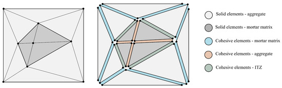 Figure 4. Generation of three sets of cohesive elements at three different phases of concrete mesostructure. The cohesive elements are generated within the mortar matrix, inside the aggregate, and in the ITZ zone.
The process of generating cohesive interface elements in different phases of the concrete mesostructure as depicted in Algorithm 1 hinges on assigning unique material IDs to different phases. For example, elements forming the mortar matrix are assigned a material ID of zero. These elements are then accessed through a for loop using their respective IDs. This allows the identification of neighboring elements, followed by the creation of cohesive nodes at their shared interfaces. This process is reiterated for different inclusions, offering a systematic approach for cohesive interface element generation.
| Algorithm 1: Algorithm to generate cohesive elements. |
| Input: FE mesh file of Abaqus |
| Output: Generated cohesive elements |
Initialization;
Construct Node Connectivity list (ndConntL);
Identification of ITZ nodes;
Identification of adjacent elements;
Assign FaceType object to adjacent elements;
Duplicating nodes;
Generation of Cohesive Elements;
|
It should be emphasized that formulating the codes to simulate concrete mesostructures encountered certain difficulties. To counter these obstacles and ensure the code’s reliability, direct engagement with Abaqus/CAE was utilized, allowing for constant monitoring of the code’s performance throughout its development. As the progression of the code development continued, essential adjustments were implemented to certify its accuracy and effectiveness in the simulation of concrete mesostructures. The primary computational challenge in generating CIEs is mesh granularity. Employing an excessively fine mesh augments the total element count significantly, consequently increasing the node connectivity list, which delineates the total elements sharing a node. This amplifies the computational burden, necessitating extended time and iterations for node-neighboring element identification and face type assignment.
4. Finite Element Modeling
4.1. Model Description
The next step after the generation of the concrete mesostructure is its discretization. In this work, all the finite element meshing operations are performed using the pre-processing functionality in Abaqus/CAE. The geometry to be discretized contains different components, e.g., mortar and aggregates, and one important aspect of the discretization process is that the finite element boundaries must coincide with different material surfaces and the continuity between their surfaces must be preserved. The free meshing technique is utilized during the discretization process to avoid restrictions on the model geometry. The geometry is meshed using three-node linear triangular elements which enable rather realistic crack propagation paths. After the discretization, the Abaqus FE mesh file is imported into the developed algorithm to generate cohesive elements. The material properties of the aggregates particles and mortar are obtained from [46] and the input parameters for different TSLs are obtained through the calibration process carried out in this paper. The material properties for mesoscale simulations of concrete material are listed in Table 2. Since the strength of aggregate particles is much higher than the other phases and the cracks normally do not propagate inside aggregates in normal concretes, the damage properties of aggregate particles are not defined.
Table 2.
Material properties. The properties of aggregate particles and mortar matrix including Young’s modulus, Poisson’s ratio, and the parameter are derived from the study conducted by [46]. The elastic stiffness of CIEs is referenced from [32]. The input parameters for the TSLs in relation to CIEs have been determined through a calibration process undertaken in the current study.
4.2. Constitutive Behavior of CIEs
The basic idea behind the cohesive zone model as first proposed by Barenblat [29,47] is to study the behavior of the material in a zone that lies directly ahead of a traction-free crack tip that nowadays is called the cohesive zone or the fracture process zone (FPZ). Barenblatt called the FPZ the terminal region and stated that since in this zone the two crack surfaces are very close to each other, they are attracted to each other with very large interatomic forces, and the degree of the forces depends upon their relative displacements.
The first cohesive crack model to simulate discrete cracks in the fracture process zone (FPZ) of concrete was introduced by Hillerborg in 1976 [31]. To describe the mechanical behavior of FPZ, the traction–separation laws (TSLs) are used. The TSLs represent the underlying relationship between the traction of a cohesive element and the corresponding relative displacement of its surfaces in the cohesive zone. Different types of TSLs have been developed for the description of engineering materials over time but all of them, in general, can be divided into two parts: the first part represents a functional relationship that describes the behavior of the material prior to the initiation of the damage and a so-called softening zone which represents the degradation of the material and its complete failure after the damage is initiated. The two parts are separated by the threshold stress above which the damage starts to initiate. The traction–separation law for mode-I and mode-II fractures can be represented, respectively, as follows [48]:
where and represent normal and shear traction, respectively, and and are crack opening displacement in the normal and shear directions, respectively. In Equation (14), f shows the nonlinear function between the traction and crack displacement.
When different fracture modes occur simultaneously on a crack tip, either by multiaxial loading of the geometry or induced by any geometry that favors multiple fracture modes under any uniaxial loading condition, then the geometry is under mixed-mode fracture states. Although the studied concrete samples in this study are loaded under the uniaxial loading condition, due to the high material heterogeneities, the cracks propagate in concrete under mixed-mode conditions rather than single-mode. Hence, its corresponding traction–separation laws are used in the finite element simulations [48]. Since bilinear TSL has a simple functional relationship and is utilized widely by many researchers in modeling heterogeneous materials such as composites, in this work, for each fracture mode, a bilinear TSL is utilized. Three model parameters must be utilized to fully characterize a bilinear TSL. These model parameters are the cohesive element penalty stiffness K, the threshold stress , and the critical fracture energy . Fracture energy can be interpreted as the required energy to form two new fractured surfaces [49]. The fracture energy can be calculated as follows:
The cohesive element penalty stiffness is the stiffness of any cohesive element in the elastic region prior to the initiation of the damage. The penalty stiffness is a function of the elastic modulus of the interface and its thickness and is calculated as follows:
where is the cohesive element thickness, and E represent the elastic modulus. Accurate definition of the penalty stiffness K is crucial to appropriately predict the structural response of concrete parts since this parameter controls how easily the cohesive elements deform elastically in the interface region. A very large K would result in immediate initiation of the damage without preceding deformation when the threshold stress is reached. This would result in a large softening region where the amount of deformation (distance between and ) leading to complete fracture would increase. On the other hand, for very small K, with a given applied displacement, the model may never reach and, thus, no damage would initiate. This state in the finite element model would result in a relatively high sliding and penetration between the nodes in the interface region.
Before initiation of the damage, the normal and shear stress can be calculated using the following equation:
where and are the penalty stiffness in the normal and shear directions, respectively. The symbol used in Equation (17) represents the Macaulay bracket. The Macaulay bracket signifies that compressive deformation or stress state would not initiate damage in the model. The quadratic stress damage criterion is employed to determine the initiation of damage. As represented in the following equation, damage is assumed to start to initiate when the function involving nominal stress ratios reaches a value of one:
where and are the tensile and shear cohesive strengths, respectively. When the stress state in the model satisfies Equation (18), with a further increase in the applied displacement, the normal and shear stress decrease. This stiffness degradation represents the start of the softening region. To represent the stiffness degradation, a scalar damage variable D is utilized. D illustrates overall damage in the model and captures all the damage mechanisms. With the further accumulation of damage, D monotonically evolves from 0 to 1 and when a complete failure occurs, its value is equal to 1. The normal and shear stress in the softening region can be obtained by:
For the linear softening, the evolution of the damage variable D can be calculated by the expression proposed by [50] as follows:
where and denote the effective displacement at damage initiation and effective displacement at complete failure, respectively, and represents the maximum value of effective displacement during the loading history. To obtain the effective displacements in Equation (20), the following expression proposed by [50] is utilized as follows:
The B-K fracture criterion [51] is utilized to capture mixed-mode fracture in composite and quasi-brittle materials. According to the B-K fracture criterion, the effective displacement at complete failure can be calculated as:
where and denote the fracture energies of mode-I and mode-II, respectively, and and represent the work done by tractions and their corresponding displacements in the normal and shear directions, respectively. According to [50], the magnitude of can be set as 1.2 for quasi-brittle materials. As is clear from Equation (22), depending on the relative contribution of mode-I and mode-II fracture, the mixed-mode fracture energy varies. Figure 5a shows a schematic representation of the mixed-mode fracture criteria.
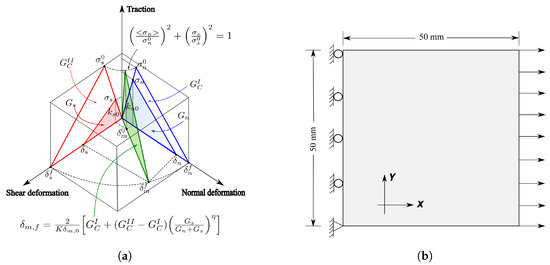
Figure 5.
Fracture criterion and boundary conditions. (a) Mixed-mode B-K fracture criterion. (b) Applied boundary conditions in mesoscale simulations.
In this paper, the finite element simulations employ traction–separation laws (TSL) with bilinear behavior to characterize the cohesive zone model. Damage initiation is determined by the quadratic stress damage criterion, while the evolution of damage in the softening region is represented by a scalar damage variable (D). To capture mixed-mode fracture behavior in composite and quasi-brittle materials, the B-K fracture criterion is applied. The provided equations define the constitutive relations utilized for the cohesive zone model in the simulations.
5. Results
In the numerical simulation of concrete, it is found that specimens with the same aggregate size distribution but with different spatial distributions show different results, especially in the softening zone. Therefore, a single numerical model is insufficient to study concrete’s overall behavior under different conditions. In this paper, a comprehensive investigation is conducted by simulating ten distinct finite element models with random aggregate distributions. The final simulation results are obtained by calculating the average of these ten individual simulations, ensuring a representative and reliable outcome for the study.
Incorporating the cohesive zone model (CZM) for concrete materials consists of two crucial steps. Initially, concrete mesostructure creation occurs through algorithms specified in Section 2, followed by model discretization. Afterwards, the model’s input file is integrated into CZM algorithms to generate cohesive elements. Although CZM proficiently depicts concrete’s complex behavior under varied boundary conditions, it is limited by model mesh dependency. Using smaller elements can mitigate this, yet it elevates computational cost due to an increased element count. Thus, a mesh sensitivity analysis is essential to strike a balance between computational efficiency and model accuracy.
5.1. Model Parameters
Three-node triangular elements (CPS3) are used to discretize the entire 2D mesoscale finite element model (see Figure 6). The cohesive zone model is mesh dependent, and during the calibration process it was found that a mesh size of 1 mm can provide a good compromise between the computational cost and a reduction in the mesh sensitivity problem. The B-K fracture criterion with quadratic nominal stress criterion and linear softening law was utilized to model the material behavior of the cohesive elements. Ten mesoscale samples, each featuring unique spatial distributions of aggregate particles, undergo multiple simulations using varied input parameters of the TSL for cohesive interface elements (CIEs). The simulation results, including stress–strain curves, are obtained by averaging the outcomes of these simulations. The stress for each stress–strain curve is determined by summing the nodal reaction forces in the constrained edge and then dividing the sum by the length of the specimen at each step frame. These stress–strain curves are then compared with experimental data. Through this comparative analysis, the input parameters of the TSL for CIEs are calibrated for mesoscale simulations. The calibrated TSL properties for different phases are listed in Table 2. A mesh size of 0.5 mm is deliberately chosen for the calibration process to mitigate, as much as possible, the mesh dependency. This discretization level results in a total of 87,000 solid elements and 130,000 CIEs. Notably, some material properties of the mortar matrix and aggregates particles are obtained from [32,46]. For the uniaxial tensile simulations, the nodes at the left boundary are constrained in the x-direction, while those at the right boundary are displaced by 0.15 mm. The applied boundary conditions are depicted in Figure 5b. To handle model nonlinearity and convergence challenges, the explicit Abaqus solver is utilized with a step time of , ensuring quasi-static loading conditions.
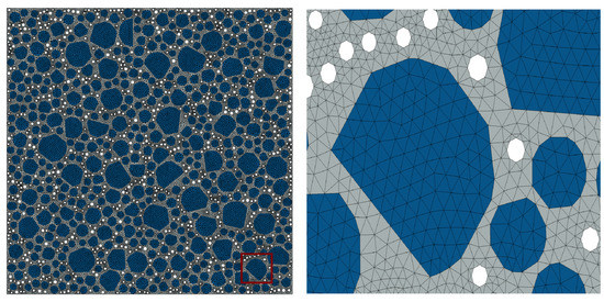
Figure 6.
The concrete sample has been discretized using a finite element method with a mesh size of 1 mm. To provide a clearer view of the mesh configuration, the elements within the red box have been magnified.
5.2. Mesh Convergence Study
For finite element simulations where the cohesive crack paths are not known in advance, rather fine levels of discretization must be used to reduce the dependence of the cohesive crack paths on the mesh size. However, reducing the element size leads to an increase in computational cost, so a balance between computational cost and accuracy must be established. To this end, a mesh convergence study is performed in this work in terms of the mean stress–strain curve and the final fracture crack paths to find an optimal mesh size. In this work, a mesoscale specimen with circular aggregates and volume fraction of 50% is discretized with six different discretization levels. After discretization, all specimens are subjected to a uniaxial tensile test simulation. Figure 7 shows the mean stress–strain curve obtained for each mesoscale specimen. The mean stress is calculated by dividing the total reaction forces of the left edge nodes by the specimen length at each step frame. As can be seen from Figure 7, the dependence of the obtained stress–strain curve is negligible for specimens with discretization steps of 1 mm and smaller than 1 mm. Figure 8 shows the final crack pattern for specimens with different mesh sizes. The propagation of macrocracks is illustrated by visualizing the so-called scaler damage variable (SDEG) of cohesive interface elements in Abaqus/CAE with a value greater than 0.9. It is worth noting that the numerical counterpart of the variable D in Equation (20) is the SDEG variable in Abaqus/CAE, so an SDEG value of zero for any CIE represents no damage and when it reaches 1, complete failure has occurred. As can be seen, the final macrocrack patterns for mesh sizes of 1 mm and smaller than 1 mm (see Figure 8c–f) are quite similar despite small differences. Considering the good agreement of the mean stress–strain curve and macrocrack pattern of the specimen with a mesh size of 1 mm with those for specimens with lower discretization levels, and taking into account the computational cost, a mesh size of 1 mm is chosen for the following finite element simulations. The convergence study in this paper highlights the critical role of fracture paths in determining the optimal mesh size, alongside stress–strain curves. While larger mesh sizes may yield comparable stress–strain curves, they can produce significantly different fracture paths. Mesh sizes below a certain value yielded consistent fracture paths and stress–strain curves, but further reduction significantly increased computational costs.
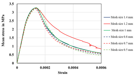
Figure 7.
Mean stress–strain curve for a concrete sample shown in Figure 8 with different levels of discretization. All mesoscale samples are subjected to a uniform displacement of 0.15 mm in the x-direction. Strain is determined by dividing the displacement at each step frame by the initial length of the specimen.
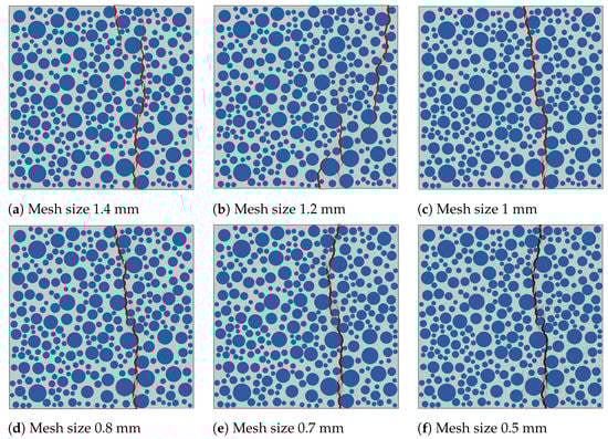
Figure 8.
Cohesive fracture paths for a unique concrete sample with different discretization levels.
5.3. Uniaxial Tension Simulation
After calibrating the input data parameters of the TSL and performing a mesh sensitivity analysis, mesoscale concrete simulations are conducted and validated against experimental results obtained from [52]. The simulations involve ten mesoscale samples with various spatial distributions and polyhedral aggregate particles, accounting for a 50% volume fraction. The samples are subjected to tensile test simulations, and the final stress–strain curves are obtained by averaging the results from each simulation. Figure 9 shows the stress–strain curve obtained from the uniaxial tensile simulations, along with the experimental data. It can be seen that the peak stress and softening behavior are close for the two curves. It should be noted, however, that a quantitative comparison is not possible here because these curves represent samples with completely different spatial distributions of aggregate particles.
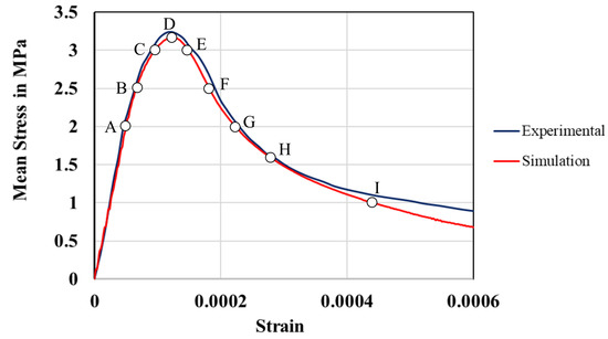
Figure 9.
Mean stress–strain curve under uniaxial tension. All mesoscale samples are subjected to a uniform displacement of 0.15 mm in the x-direction. Strain is determined by dividing the displacement at each step frame by the initial length of the specimen.
5.4. Propagation of Microcracks and Formation of Macrocracks
To illustrate the formation and propagation of microcracks leading to the formation of macrocracks, the mesoscale concrete specimen with smoothed polyhedral aggregates with a total volume fraction of 50% without voids is utilized. As shown in Figure 10, the formation of macrocracks in eight continuous phases is illustrated. The corresponding value of each stage within the mean stress–strain curve is depicted by marked points in Figure 9. To better visualize the generated microcracks, the displacement values are enlarged by a factor of 50. This is achieved by changing the deformation scale variable in the visualization module of Abaqus/CAE. Figure 10a (marked point A in Figure 9) shows that very few microcracks occur at low stress. As can be seen in Figure 10b (marked point B in Figure 9), as the deformation continues and the average stress value increases, more microcracks appear. Since the ITZ zone is the weakest zone within the concrete structure, the initiation and propagation of microcracks occur mainly in this zone. Figure 10c shows the marked point C, which is located in the nonlinear part of the pre-crack zone. As can be seen, the propagating microcracks have complex patterns and run approximately perpendicular to the loading direction. Furthermore, no coalescence of microcracks into a macrocrack is observed before reaching the peak stress, and a few microcracks are located within the mortar matrix. This is due to the relatively high cohesive strength of the mortar matrix compared to the ITZ zone. As can be seen from Figure 10d, with increasing displacement, some cracks located in the ITZ zone continue to propagate and merge with the newly formed microcracks in the mortar matrix. At this stage, a macrocrack is generated and the softening process in the mean stress–strain curve begins (see Figure 9). The onset of the softening process is followed by the localization of stresses. As can be seen in Figure 11, there is no localized stress in the concrete specimen before point D, but after the peak stress is reached, the localization of the stress begins. If the displacement is further increased, the specimen will fail due to the further propagation of the generated macrocrack at stage D and the generation and propagation of a new macrocrack. In the subsequent analysis, a sensitivity study is conducted to assess the influence of factors such as aggregate content, volume porosity, and aggregate shape on the mesoscale fracture behavior of concrete.
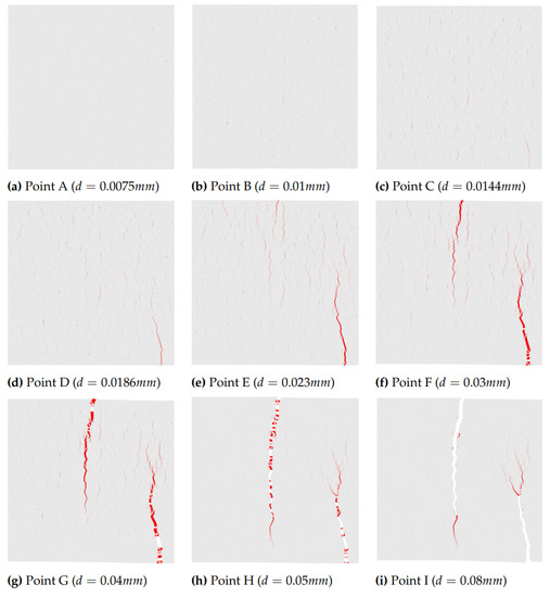
Figure 10.
The evolution of pre-peak microcracking and post-peak macrocracking for the concrete mesoscale sample depicted at various stages. The corresponding value of each stage on the mean stress–strain curve is illustrated in Figure 9. For the sake of clarity, the three phases of concrete at the mesoscale are not illustrated.
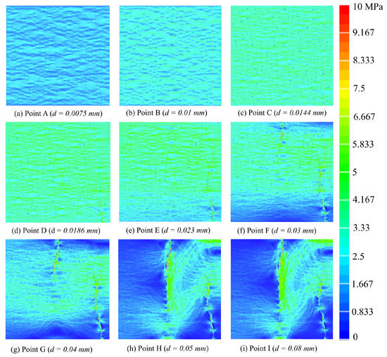
Figure 11.
Development of von Mises stress state at different stages of tensile loading. The corresponding point of each stage on the mean stress–strain curve is illustrated in Figure 9.
5.5. Effect of Aggregate Content
The effect of the aggregate content is studied on concrete microstructures with polyhedral aggregates and no void content. To reduce the effects of microstructural heterogeneity, mesoscale simulations are performed on ten mesoscale specimens with the same aggregate content but with different spatial distributions of aggregates. The average stress–strain curve for each aggregate content is obtained by averaging the results of ten mesoscale simulations. The Fuller’s curve is employed to determine the size distribution of aggregates in concrete specimens with 50%, 35%, and 20% coarse aggregate content. Table 3 shows the volume fraction of the individual size segments in the concrete structure with different aggregate contents. Figure 12 shows the concrete samples with three different coarse aggregate volume fractions and the corresponding mean stress–strain curve is plotted in Figure 13. It can be seen that the average load capacity decreases by 8%, from 3.45 MPa to 3.2 MPa, when the volume fraction of aggregate is increased from 20% to 50%. This is due to the fact that increasing the volume fraction of coarse aggregate increases the volume of the weak aggregate–mortar interface. It can also be observed that the overall elastic modulus of the concrete structure increases due to the increase in aggregate content. This is due to the significantly higher elastic modulus of the aggregate compared to the mortar matrix [53].
Table 3.
Contribution of segmented aggregate size in concrete microstructures with different volume fraction of coarse aggregates.
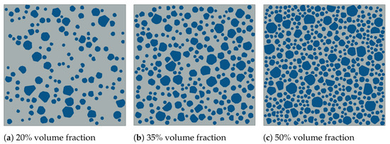
Figure 12.
Concrete mesostructure with different levels of coarse aggregate volume fraction.
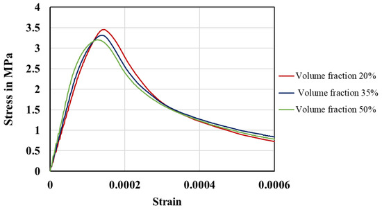
Figure 13.
Influence of aggregate volume fraction. All mesoscale samples are subjected to a uniform displacement of 0.15 mm in the x-direction. Strain is determined by dividing the displacement at each step frame by the initial length of the specimen.
5.6. Effect of Volume Porosity
To study the effects of porosity volume fraction, circular voids are created and randomly distributed within the concrete mesostructure specimens, representing 2.5% and 5% of the total volume fraction of the concrete specimen. The circular voids have diameters between 1 mm and 2 mm. Figure 14 shows a concrete mesostructure containing smoothed polyhedral aggregates with the aggregate volume ratio of 50% and porosity contents of 2.5% and 5%. The corresponding average stress–strain curve is shown in Figure 15. For each porosity volume fraction, a set of ten concrete specimens is generated and simulated under the uniaxial tensile state, and the averaged mean stress–strain curve is obtained by statistical analysis on the simulation results for each porosity content. As Figure 15 shows, the mean tensile strength decreases from 3.2 MPa to 2.5 MPa when the volume porosity increases from 0% to 5%. The reason for this is that the voids reduce the surface area available to support the imposed load. As a consequence, they provide easier paths for crack propagation and, thus, encourage the formation of small cracks initiating within the ITZ zone. From Figure 14, it can be seen that the macrocrack leading to specimen failure propagates through the voids when possible and it takes the path of least resistance to fracture the concrete specimen.
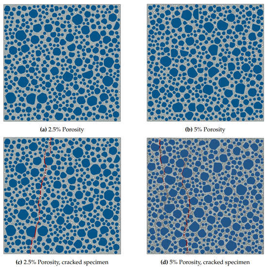
Figure 14.
Simulated crack pattern for samples with different volume fractions of porosity in 5 times magnification.
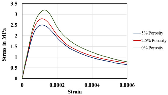
Figure 15.
Effect of volume fraction of porosity. All mesoscale samples are subjected to a uniform displacement of 0.15 mm in the x-direction. Strain is determined by dividing the displacement at each step frame by the initial length of the specimen.
It is also found that in mesoscale simulations, two different macrocrack patterns lead to the complete failure of concrete specimens. In the first type, the coalescence of microcracks leads to the formation of one macrocrack that passes through the specimen and leads to the complete failure of the specimen. In the second type, the coalescence of microcracks leads to the formation of two or more macrocracks leading to complete specimen failure (see Figure 14). The difference between these two macrocracks leads to different energy dissipation so that more energy is dissipated in the second type than in the first type.
5.7. Effect of Aggregate Shape
In order to analyze the effect of the geometric shape of the aggregate on the maximum tensile strength and load capacity immediately after the onset of the softening zone, concrete specimens are generated with circular, elliptical, smoothed polyhedral, and polyhedral aggregates with sharp edges. It is worth noting that 12 random points are used to generate smoothed polyhedral aggregates, while only 8 random points are used for polyhedral aggregates with sharper edges. For each aggregate shape, five concrete specimens are generated, and after simulation under uniaxial tensile loading, the corresponding average stress–strain curve is obtained from the simulation results. In this study, the total volume fraction of coarse aggregate is 50%, and there is no void in the generated specimens. Figure 16 shows the generated concrete mesostructures with different aggregate shapes and their corresponding mean stress–strain curves are depicted in Figure 17. The results show that the tensile strength and load capacity of circular, elliptical, and smoothed polyhedral aggregates are greater than those of sharp-edged polyhedral aggregates, while the difference between the tensile strength of circular, elliptical, and smoothed polyhedral aggregates is negligible. This can be explained by the high local stress concentration at the corner of the polyhedral aggregates with sharp edges [53]. The smoothed edges of circular, elliptical, and smoothed polyhedral aggregates lead to a more uniform stress distribution and, thus, delay the fracture process and thus increase the maximum tensile strength.
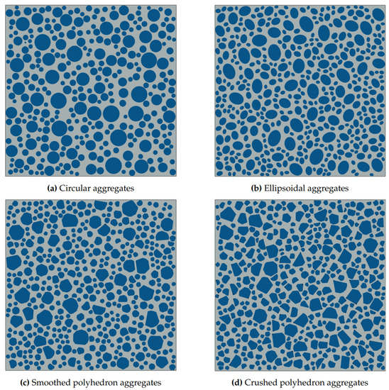
Figure 16.
Concrete mesostructures with different aggregate shapes.
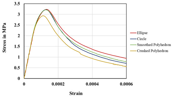
Figure 17.
Influence of aggregate geometrical configuration. All mesoscale samples are subjected to a uniform displacement of 0.15 mm in the x-direction. Strain is determined by dividing the displacement at each step frame by the initial length of the specimen.
6. Conclusions
Two different effective and efficient algorithms are developed to realize the propagation of cracks and fracture of concrete specimens at the mesoscale using the finite element method. In the first algorithm, concrete mesostructures with randomly distributed circular, elliptical, or polygonal aggregate shapes and circular voids are generated. In the second algorithm, zero-thickness two-dimensional cohesive interface elements (CIEs) are generated and inserted into the interfaces of solid elements. The developed algorithm is capable of generating zero-thickness two-dimensional cohesive interface elements (i) within the elements constituting the mortar matrix, (ii) within the elements constituting the aggregates, and (iii) in the ITZ zone. In the parametric studies conducted, the effect of the volume fraction of the aggregate, the shape of the aggregate, and the total volume fraction of the porosity content is studied on the mechanical response at the structural level. In each analysis, 10 different model realizations are created for each given mesostructural parameter and the final response is determined using statistical analysis. In this way, the effect of varying the spatial distribution of the rock particles in each model realization is minimized. The results showed that:
- The methodology developed for mesoscale simulation of concrete crack propagation and failure is capable of reproducing the concrete fracture properties observed in numerical and experimental studies in the literature [13,32,53,54,55,56,57,58].
- Two different macrocrack patterns are observed in the mesoscale simulation of concrete specimens under the uniaxial tension loading condition. In the first type, the microcracks merge to form a failure macrocrack. This type of macrocrack leads to a sharp decrease in the load-carrying capacity of the concrete specimen immediately after the onset of the softening zone. Thus, less energy is dissipated until complete failure. In the second type, the coalescence of microcracks leads to the formation of two or more failure macrocracks. In this condition, a more gradual softening response is observed, and, therefore, more energy is dissipated until complete failure.
- Under tensile loading of concrete specimens, the damage starts to initiate first in the ITZ zone, which is known to be the weakest phase, and as the specimen is further loaded, the microcracks propagate through the mortar matrix, resulting in a decrease in the stiffness of the concrete.
- The tensile strength and strain at which the softening zone begins are lower for the crushed aggregates than for the circular and elliptical aggregates. This can be explained by the local stress concentration at the sharp edges of the crushed aggregates. Therefore, the strength of the concrete may be overestimated in the mesoscale simulation with circular and elliptical aggregates.
- It is found that the modulus of elasticity of concrete is linearly proportional to the total volume fraction of aggregate particles, whereas the ductility of concrete is inversely proportional to the volume fraction of aggregates.
- An increase in the volume fraction of coarse aggregate leads to a reduction in the maximum tensile strength and the load-carrying capacity of the concrete specimens. This can be explained, on the one hand, by the increase in the weak aggregate–mortar interface and, on the other hand, by enhanced crack bridging mechanisms, especially in zones where a higher concentration of aggregates is observed.
- An increase in the total volume fraction of porosity leads to a reduction in the maximum tensile strength and load-bearing capacity. This is attributed to the fact that a higher content of voids facilitates the initiation and propagation of cracks. This case shows the importance of considering voids in the mechanical and fracture modeling of concretes with high void content.
It is worth mentioning that all the above conclusions were obtained by finite element simulations of concrete specimens under tensile loading. The algorithms for cohesive interface elements and concrete microstructures exhibit broad applicability in practical engineering, regardless of the concrete’s design, composition, or aggregate materials. They can accommodate multiple material composites, model dynamic loading conditions, and facilitate coupled multiphysics analysis for environmental exposures. Additionally, the algorithms have no constraints on aggregate selection or material properties, allowing for flexible applications, such as studying aggregate grading impacts, extension to 3D simulations and complex geometries, or integration into multiscale modeling approaches. Furthermore, the algorithms’ flexibility enables crack propagation within aggregates when their material properties are equivalent or inferior to those of the mortar matrix. This adaptability allows the investigation of concrete behavior under diverse conditions, material design optimization, and connection of microstructural details with macroscopic performance, advancing concrete engineering practices. This conclusion emphasizes the robustness and versatility of the proposed algorithms, aligning with the feedback provided.
Explicitly considering specific strength and toughness parameters in the mesostructural optimization of concrete materials, including the design and placement of microscopic components such as aggregates, cement paste, and potential admixtures, is crucial for enhancing the durability and performance of structures. This approach allows tailoring concrete materials to their intended applications, ranging from high-strength mixes for skyscrapers to earthquake-resistant configurations. Furthermore, mesoscale simulations in this research have proven to be effective tools for comprehending the intricate behavior of concrete materials under various conditions. The results establish a direct relationship between mesostructural properties, such as aggregate size, volume fraction, porosity, and shape, and macroscopic performance characteristics, including tensile strength, ductility, and load-bearing capacity. These findings emphasize the significant role of mesostructural optimization in advancing concrete construction methods and enhancing the performance and safety of concrete structures.
An intrinsic problem in modeling crack propagation using the cohesive zone model is its mesh dependency. One way to address this problem is to implement a finer level of discretization, which leads to higher computational costs. In future work, the authors intend to implement a novel cohesive phase-field fracture approach to simulate crack propagation in the concrete structure. A comprehensive comparison of cohesive zone modeling and cohesive phase-field fracture with respect to the mesoscale simulation of fracture in concrete materials would be the focus of a future study.
Author Contributions
R.N.K.: conceptualization, methodology, software, validation, visualization, investigation, resources, writing—original draft, review, and editing. N.R.: supervision, review and editing, project administration, funding acquisition. R.L.: supervision, review and editing, project administration, funding acquisition. All authors have read and agreed to the published version of the manuscript.
Funding
This work is funded by dtec.bw—Digitalization and Technology Research Center of the Bundeswehr which we gratefully acknowledge. dtec.bw is funded by the European Union—NextGenerationEU.
Data Availability Statement
The developed algorithms can be provided upon request.
Conflicts of Interest
The authors declare no conflict of interest.
References
- Yılmaz, O.; Molinari, J.F. A mesoscale fracture model for concrete. Cem. Concr. Res. 2017, 97, 84–94. [Google Scholar] [CrossRef]
- Unger, J.F.; Eckardt, S. Multiscale modeling of concrete. Arch. Comput. Methods Eng. 2011, 18, 341–393. [Google Scholar] [CrossRef]
- Wang, X.; Yang, Z.J.; Yates, J.; Jivkov, A.; Zhang, C. Monte Carlo simulations of mesoscale fracture modelling of concrete with random aggregates and pores. Constr. Build. Mater. 2015, 75, 35–45. [Google Scholar] [CrossRef]
- Yang, Z.J.; Li, B.B.; Wu, J.Y. X-ray computed tomography images based phase-field modeling of mesoscopic failure in concrete. Eng. Fract. Mech. 2019, 208, 151–170. [Google Scholar] [CrossRef]
- Li, S.; Li, Q. Method of meshing ITZ structure in 3D meso-level finite element analysis for concrete. Finite Elem. Anal. Des. 2015, 93, 96–106. [Google Scholar] [CrossRef]
- Zhang, Z.; Song, X.; Liu, Y.; Wu, D.; Song, C. Three-dimensional mesoscale modelling of concrete composites by using random walking algorithm. Compos. Sci. Technol. 2017, 149, 235–245. [Google Scholar] [CrossRef]
- Xiao, J.; Zhang, X.; Zhang, D.; Xue, L.; Sun, S.; Stránskỳ, J.; Wang, Y. Morphological reconstruction method of irregular shaped ballast particles and application in numerical simulation of ballasted track. Transp. Geotech. 2020, 24, 100374. [Google Scholar] [CrossRef]
- Naderi, S.; Zhang, M. An integrated framework for modelling virtual 3D irregulate particulate mesostructure. Powder Technol. 2019, 355, 808–819. [Google Scholar] [CrossRef]
- Van Mier, J.; Van Vliet, M. Influence of microstructure of concrete on size/scale effects in tensile fracture. Eng. Fract. Mech. 2003, 70, 2281–2306. [Google Scholar] [CrossRef]
- Leite, J.; Slowik, V.; Mihashi, H. Computer simulation of fracture processes of concrete using mesolevel models of lattice structures. Cem. Concr. Res. 2004, 34, 1025–1033. [Google Scholar] [CrossRef]
- Eliáš, J.; Stang, H. Lattice modeling of aggregate interlocking in concrete. Int. J. Fract. 2012, 175, 1–11. [Google Scholar] [CrossRef]
- Grassl, P.; Grégoire, D.; Solano, L.R.; Pijaudier-Cabot, G. Meso-scale modelling of the size effect on the fracture process zone of concrete. Int. J. Solids Struct. 2012, 49, 1818–1827. [Google Scholar] [CrossRef]
- López, C.M.; Carol, I.; Aguado, A. Meso-structural study of concrete fracture using interface elements. I: Numerical model and tensile behavior. Mater. Struct. 2008, 41, 583–599. [Google Scholar] [CrossRef]
- Wang, Z.; Kwan, A.; Chan, H. Mesoscopic study of concrete I: Generation of random aggregate structure and finite element mesh. Comput. Struct. 1999, 70, 533–544. [Google Scholar] [CrossRef]
- Schlangen, E.; Van Mier, J. Simple lattice model for numerical simulation of fracture of concrete materials and structures. Mater. Struct. 1992, 25, 534–542. [Google Scholar] [CrossRef]
- Schlangen, E.; Garboczi, E.J. Fracture simulations of concrete using lattice models: Computational aspects. Eng. Fract. Mech. 1997, 57, 319–332. [Google Scholar] [CrossRef]
- Bolander, J., Jr.; Saito, S. Fracture analyses using spring networks with random geometry. Eng. Fract. Mech. 1998, 61, 569–591. [Google Scholar] [CrossRef]
- Cusatis, G.; Bažant, Z.P.; Cedolin, L. Confinement-shear lattice CSL model for fracture propagation in concrete. Comput. Methods Appl. Mech. Eng. 2006, 195, 7154–7171. [Google Scholar] [CrossRef]
- D’Addetta, G.A.; Ramm, E. A microstructure-based simulation environment on the basis of an interface enhanced particle model. Granul. Matter 2006, 8, 159–174. [Google Scholar] [CrossRef]
- Zubelewlcz, A.; Bažant, Z.P. Interface element modeling of fracture in aggregate composites. J. Eng. Mech. 1987, 113, 1619–1630. [Google Scholar] [CrossRef]
- Ma, G.; Xie, Y.; Long, G.; Tang, Z.; Zhou, X.; Zeng, X.; Li, J. Mesoscale investigation on concrete creep behaviors based on discrete element method. Constr. Build. Mater. 2022, 342, 127957. [Google Scholar] [CrossRef]
- Yu, Y.; Zheng, Y.; Zhao, X.Y. Mesoscale modeling of recycled aggregate concrete under uniaxial compression and tension using discrete element method. Constr. Build. Mater. 2021, 268, 121116. [Google Scholar] [CrossRef]
- Zhang, Z.; Guo, J.; Zhang, Z.; Song, X. Mesoscale damage modelling of concrete by using image-based scaled boundary finite element method. Int. J. Damage Mech. 2021, 30, 1281–1311. [Google Scholar] [CrossRef]
- Yu, J.C.; Wang, J.T.; Pan, J.W.; Guo, N.; Zhang, C.H. A dynamic FEM-DEM multiscale modeling approach for concrete structures. Eng. Fract. Mech. 2023, 278, 109031. [Google Scholar] [CrossRef]
- Sherzer, G.L.; Alghalandis, Y.F.; Peterson, K.; Shah, S. Comparative study of scale effect in concrete fracturing via Lattice Discrete Particle and Finite Discrete Element Models. Eng. Fail. Anal. 2022, 135, 106062. [Google Scholar] [CrossRef]
- Caballero, A.; López, C.; Carol, I. 3D meso-structural analysis of concrete specimens under uniaxial tension. Comput. Methods Appl. Mech. Eng. 2006, 195, 7182–7195. [Google Scholar] [CrossRef]
- Wriggers, P.; Moftah, S. Mesoscale models for concrete: Homogenisation and damage behaviour. Finite Elem. Anal. Des. 2006, 42, 623–636. [Google Scholar] [CrossRef]
- Haefner, S.; Eckardt, S.; Koenke, C. A geometrical inclusion-matrix model for the finite element analysis of concrete at multiple scales. In Proceedings of the 16th IKM 2003, Weimar, Germany, 10–12 June 2003. [Google Scholar]
- Barenblatt, G.I. The formation of equilibrium cracks during brittle fracture. General ideas and hypotheses. Axially-symmetric cracks. J. Appl. Math. Mech. 1959, 23, 622–636. [Google Scholar] [CrossRef]
- Dugdale, D.S. Yielding of steel sheets containing slits. J. Mech. Phys. Solids 1960, 8, 100–104. [Google Scholar] [CrossRef]
- Hillerborg, A.; Modéer, M.; Petersson, P.E. Analysis of crack formation and crack growth in concrete by means of fracture mechanics and finite elements. Cem. Concr. Res. 1976, 6, 773–781. [Google Scholar] [CrossRef]
- Wang, X.; Zhang, M.; Jivkov, A.P. Computational technology for analysis of 3D meso-structure effects on damage and failure of concrete. Int. J. Solids Struct. 2016, 80, 310–333. [Google Scholar] [CrossRef]
- Rezaei, S.; Mianroodi, J.R.; Khaledi, K.; Reese, S. A nonlocal method for modeling interfaces: Numerical simulation of decohesion and sliding at grain boundaries. Comput. Methods Appl. Mech. Eng. 2020, 362, 112836. [Google Scholar] [CrossRef]
- Ying, J.; Guo, J. Fracture Behaviour of Real Coarse Aggregate Distributed Concrete under Uniaxial Compressive Load Based on Cohesive Zone Model. Materials 2021, 14, 4314. [Google Scholar] [CrossRef] [PubMed]
- Chen, J.; Ouyang, X.; Sun, X. Numerical Investigation of Asphalt Concrete Fracture Based on Heterogeneous Structure and Cohesive Zone Model. Appl. Sci. 2022, 12, 11150. [Google Scholar] [CrossRef]
- Zhang, B.; Nadimi, S.; Eissa, A.; Rouainia, M. Modelling fracturing process using cohesive interface elements: Theoretical verification and experimental validation. Constr. Build. Mater. 2023, 365, 130132. [Google Scholar] [CrossRef]
- Luo, Q.; Wang, W.; Sun, Z.; Wang, B.; Xu, S. Statistical analysis of mesoscopic concrete with random elastic modulus. J. Build. Eng. 2021, 33, 101850. [Google Scholar] [CrossRef]
- Naderi, S.; Zhang, M. Meso-scale modelling of static and dynamic tensile fracture of concrete accounting for real-shape aggregates. Cem. Concr. Compos. 2021, 116, 103889. [Google Scholar] [CrossRef]
- Naderi, S.; Zhang, M. 3D meso-scale modelling of tensile and compressive fracture behaviour of steel fibre reinforced concrete. Compos. Struct. 2022, 291, 115690. [Google Scholar] [CrossRef]
- Guinea, G.; El-Sayed, K.; Rocco, C.; Elices, M.; Planas, J. The effect of the bond between the matrix and the aggregates on the cracking mechanism and fracture parameters of concrete. Cem. Concr. Res. 2002, 32, 1961–1970. [Google Scholar] [CrossRef]
- Wittmann, F.; Roelfstra, P.; Sadouki, H. Simulation and analysis of composite structures. Mater. Sci. Eng. 1985, 68, 239–248. [Google Scholar] [CrossRef]
- Roelfstra, P. A Numerical Approach to Investigate the Properties of Numerical Concrete. Ph.D. Thesis, EPFL-Lausanne, Lausanne, Switzerland, 1989. [Google Scholar]
- Zohdi, T. Computational optimization of the vortex manufacturing of advanced materials. Comput. Methods Appl. Mech. Eng. 2001, 190, 6231–6256. [Google Scholar] [CrossRef]
- Zhou, R.; Song, Z.; Lu, Y. 3D mesoscale finite element modelling of concrete. Comput. Struct. 2017, 192, 96–113. [Google Scholar] [CrossRef]
- Jarvis, R.A. On the identification of the convex hull of a finite set of points in the plane. Inf. Process. Lett. 1973, 2, 18–21. [Google Scholar] [CrossRef]
- Xiong, X.; Xiao, Q. Meso-scale simulation of concrete based on fracture and interaction behavior. Appl. Sci. 2019, 9, 2986. [Google Scholar] [CrossRef]
- Barenblatt, G.I. The mathematical theory of equilibrium cracks in brittle fracture. Adv. Appl. Mech. 1962, 7, 55–129. [Google Scholar]
- Xi, X.; Yang, S.; Li, C.Q.; Cai, M.; Hu, X.; Shipton, Z.K. Meso-scale mixed-mode fracture modelling of reinforced concrete structures subjected to non-uniform corrosion. Eng. Fract. Mech. 2018, 199, 114–130. [Google Scholar] [CrossRef]
- Schwalbe, K.; Scheider, I.; Cornec, A. Guidelines for Applying Cohesive Models to the Damage Behaviour of Engineering Materials and Structures; Springer: Berlin/Heidelberg, Germany, 2013. [Google Scholar]
- Camanho, P.P.; Dávila, C.G. Mixed-Mode Decohesion Finite Elements for the Simulation of Delamination in Composite Materials; No. NAS 1.15: 211737; Technical Report; NASA: Washington, DC, USA, 2002. [Google Scholar]
- Benzeggagh, M.L.; Kenane, M. Measurement of mixed-mode delamination fracture toughness of unidirectional glass/epoxy composites with mixed-mode bending apparatus. Compos. Sci. Technol. 1996, 56, 439–449. [Google Scholar] [CrossRef]
- Ren, X.; Yang, W.; Zhou, Y.; Li, J. Behavior of high-performance concrete under uniaxial and biaxial loading. ACI Mater. J. 2008, 105, 548. [Google Scholar]
- Kim, S.M.; Al-Rub, R.K.A. Meso-scale computational modeling of the plastic-damage response of cementitious composites. Cem. Concr. Res. 2011, 41, 339–358. [Google Scholar] [CrossRef]
- Hordijk, D.A. Tensile and tensile fatigue behaviour of concrete; experiments, modelling and analyses. Heron 1992, 37, 79. [Google Scholar]
- Rodrigues, E.A.; Manzoli, O.L.; Bitencourt, L.A., Jr.; Bittencourt, T.N. 2D mesoscale model for concrete based on the use of interface element with a high aspect ratio. Int. J. Solids Struct. 2016, 94, 112–124. [Google Scholar] [CrossRef]
- Du, X.; Jin, L.; Ma, G. Numerical modeling tensile failure behavior of concrete at mesoscale using extended finite element method. Int. J. Damage Mech. 2014, 23, 872–898. [Google Scholar] [CrossRef]
- Guo, H.; Ooi, E.; Saputra, A.; Yang, Z.; Natarajan, S.; Ooi, E.; Song, C. A quadtree-polygon-based scaled boundary finite element method for image-based mesoscale fracture modelling in concrete. Eng. Fract. Mech. 2019, 211, 420–441. [Google Scholar] [CrossRef]
- Yu, J.; Li, G.; Ren, Z.; Wei, Z.; Tang, J.; Li, Z.; Si, X.; Zhao, Z. Mixed-mode I-II mesoscale fracture behavior of concrete determined by the realistic aggregate numerical model. Constr. Build. Mater. 2019, 226, 802–817. [Google Scholar] [CrossRef]
Disclaimer/Publisher’s Note: The statements, opinions and data contained in all publications are solely those of the individual author(s) and contributor(s) and not of MDPI and/or the editor(s). MDPI and/or the editor(s) disclaim responsibility for any injury to people or property resulting from any ideas, methods, instructions or products referred to in the content. |
© 2023 by the authors. Licensee MDPI, Basel, Switzerland. This article is an open access article distributed under the terms and conditions of the Creative Commons Attribution (CC BY) license (https://creativecommons.org/licenses/by/4.0/).