Article

Performance Analysis and Testing of Spiral Quantitative Fertiliser Distributors in Orchards

1
College of Mechanical Electrification Engineering, Tarim University, Alaer 843300, China
2
Mechanical Equipment Research Institute of Xinjiang Academy of Agricultural Reclamation Sciences, Shihezi 832000, China
*
Author to whom correspondence should be addressed.
Appl. Sci. 2023, 13(15), 8941; https://doi.org/10.3390/app13158941
Submission received: 30 June 2023 / Revised: 25 July 2023 / Accepted: 2 August 2023 / Published: 3 August 2023
(This article belongs to the Section Robotics and Automation)

Abstract

:
This study designed two levels of quantitative fertilizer distribution to investigate precision fertilization applications in orchards in South Xinjiang, China, which have vast rows and narrow plant spaces. The machine comprised a base frame, a ditching device, a fertilizing apparatus and an earth-covering device. The design parameters of the flow stabilization screw, conveyor screw and single-ring fertilizer quantity were summarised using theoretical analysis. The single-ring fertilizer quantity of the conveyor screw was verified via an experiment by combining EDEM software. Three-factor and three-level Box–Behnken tests were conducted using the spiral rotation speed of the conveyor, advancing of the speed and the opening degree of fertilizer outlet as the test factors and using the coefficient of variation (CV) of uniformity as the test index—thus obtaining the optimal working parameters. The simulation test results revealed that the single-ring fertilizer quantity of the fertilizing apparatus was 145.6 g, fulfilling the design requirements. The prototype testing results showed that the CV of uniformity was 6.521% when the spiral rotation speed of the conveyor, the opening degree of the fertilizer outlet and the advancing speed were 66 RPM, 42% and 2.7 km/h—thus meeting the needs of precision fertilization operations. The two designed levels of the quantitative fertilizer distributors were applied to fertilization processes in orchards with wide-row spaces and narrow plant spaces in South Xinjiang, China and were able to effectively carry out the precision fertilization applications. These data could also provide references for the optimization of spiral quantitative fertilizer distributors.

1. Introduction

To promote sustainable development, small and densely planted orchards are being converted into wide-row spacing and narrow-spacing orchards on the southern border of China [1]. In these new orchards, chemical fertilizers are widely used to increase the quality and yield of forest fruits [2,3]. Compared with organic fertilizers, chemical fertilizers have strict control of application rates [4,5] and the fertilizer application requires a high degree of uniformity. The discharge performance of the fertilizer discharge device is the key. The traditional external groove wheel, impeller, scraper, staggered tooth and spiral-type [6,7,8,9,10,11] and other fertilizer applicators are commonly used in agricultural fertilizers. For the new orchard planting mode on the southern border, the existing fertilizer applicator fertilization effect is unsatisfactory and cannot be adapted. There is an urgent need to improve traditional fertilizer application methods—particularly for the development of a quantitative fertilizer applicator suitable for orchards on the southern border, to ensure both the uniformity and precision of fertilizer application.
Scholars have conducted several studies on developing solutions to uneven fertilization distribution. Existing studies have mainly focused on the design improvement and optimization of fertilizer distributors. Among them, the spiral fertilizer distributor has been extensively used for its simple structure, closed conveying environment, adjustable conveying capacity and stable single-ring conveying capacity [12,13,14]. Qian et al. [15] proposed that, compared with single-screw conveying, double-screw conveying has the advantages of a strong conveying capacity and low energy consumption. Zhan et al. [16] used a single-axis bidirectional screw fertilizer discharging device to achieve simultaneous fertilizer discharge at the left and right ends, and the uniformity of fertilizer application meets the requirements of agronomic fertilizer application. Chen Xiongfei et al. [17] designed a double-layer spiral discharging device to carry out a discharging test on different composite fertilizers, effectively improving the Fertilizer discharge effect. Ton Guoqiang et al. [18] first investigated the characteristics of spiral fertilizer discharge. On this basis, data describing the arc double spiral fertilizer discharger—through simulations and experimental verification of its optimization—showed that the optimized arc groove double-spiral fertilizer discharger’s fertilizer discharge uniformity is good, effectively solving the problem of uneven fertilizer discharge in single spiral fertilizer dischargers. Xing [19] used EDEM software to study fertilizer application processes. Simulation analysis was undertaken to determine the structural parameters of the two-stage spiral and was verified through testing to provide a theoretical basis for the development of fertilizer application devices. As a result of this research, the two-stage spiral fertilizer applicator showed superior fertilizer discharge. At the same time, through simulations and experimental comparative validation, this applicator effectively improved the fertilizer application performance of the equipment. However, further optimization and research are required for orchards with wide-row spacing and narrow spacing along the southern Chinese border.
A spiral quantitative fertilizer distributor for orchards is designed in this study. The design parameters of the conveyor screw and single-ring fertilizer quantity are concluded through the theory of fertilizing quantity per single fruit tree. The fertilizer distribution performances of the conveyor screw are verified using EDEM software. The spiral rotation speed of the conveyor, the advancing speed and the opening degree of the fertilizer outlet are optimized through three-factor and three-level Box–Behnken tests. The fertilization performances of the prototype under the optimal parameters are verified via a field test. This study has important theoretical and practical significance in promoting the mechanical development of fertilizer distribution and increasing farmers’ income in orchards in South Xinjiang.

2. Materials and Methods

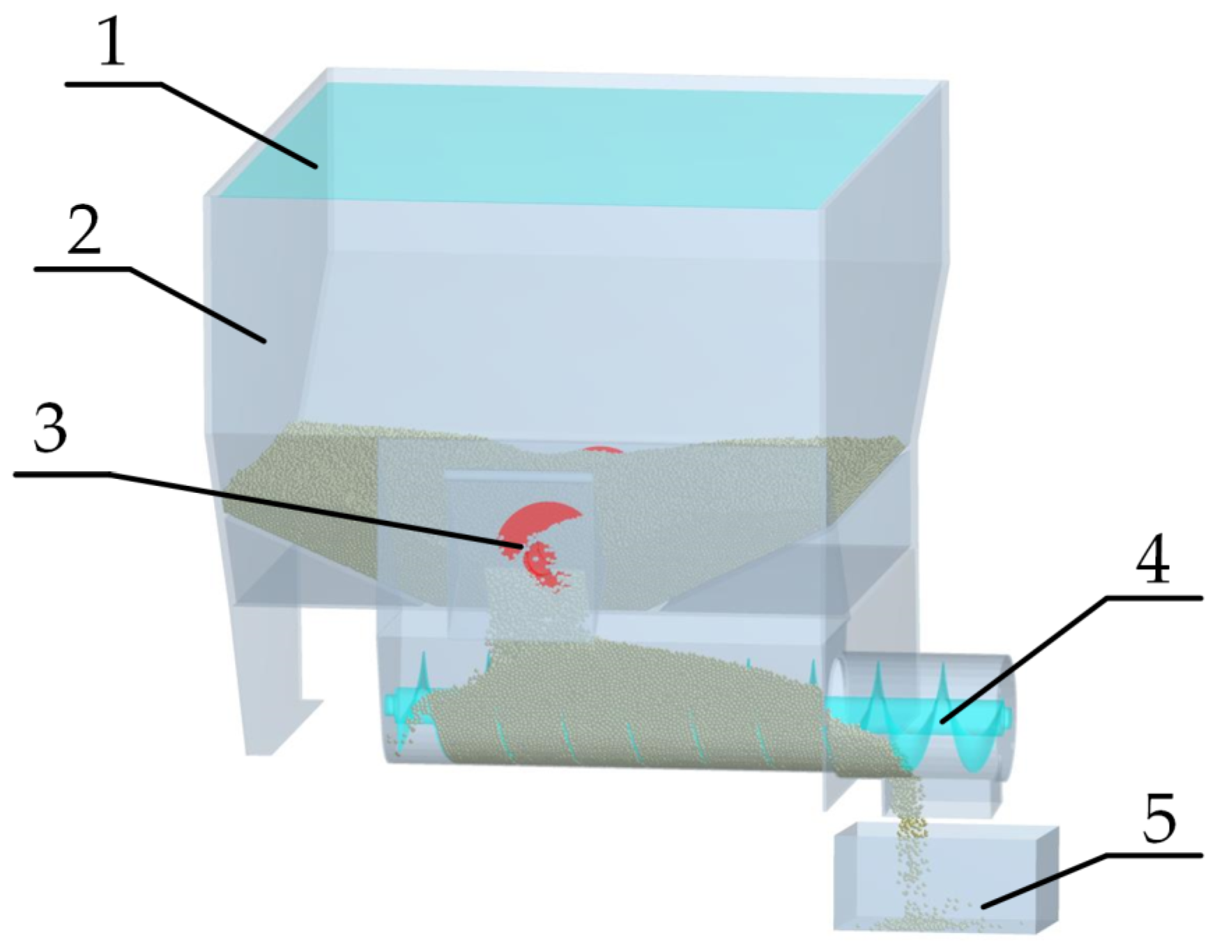
2.1. Overall Structure and Working Principle of the Fertilizer Distributor

The overall structure of the fertilizer distributor was primarily comprised of a base frame, a ditching device, a fertilizing apparatus and an earth-covering device (Figure 1). The earth-covering device was fixed with the base frame through bolts. The ditching device was below the earth-covering device and was set with the base frame by a piece of the short axis. The fertilizing apparatus was placed on the base frame and fixed with the base frame through welding. The whole structure was connected to the rear part of the tractor via a three-point suspension. During the operation of the fertilizer distributor, the tractor transmitted the power to the ditching device and fertilizing apparatus, respectively. The cutter disc of the ditching device rotated to dig ditches. The fertilizing apparatus regulated the fertilizing quantity by controlling the fertilizer outlet’s opening degree and the conveyor’s spiral rotation speed. Finally, the earth-covering device was responsible for covering soils.

2.2. Design of Critical Parts

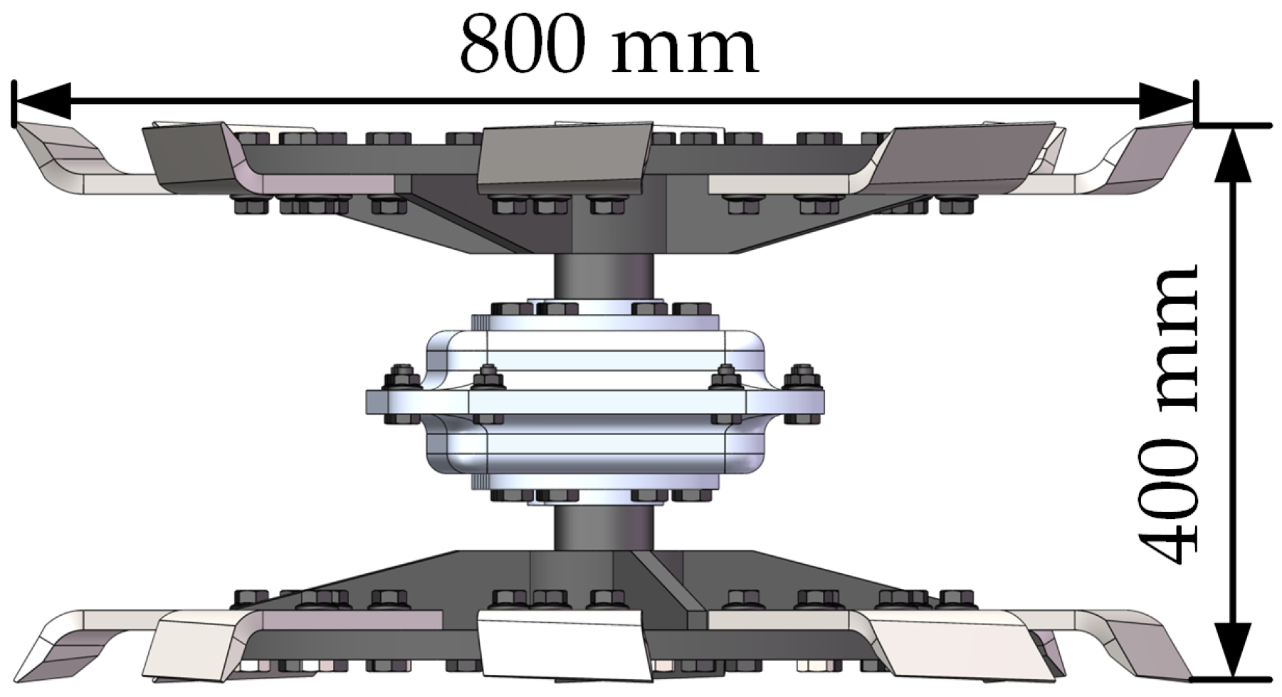
2.2.1. Fertilizing Tank

This spiral fertilizer distributor was comprised of two fertilizing tanks, and the total fertilizer capacity was 0.8 m3. The upper tank delivered fertilizer downward quantitatively, and the lower tank was used for quantitative fertilizing. To ensure the smooth flow of fertilizers in the upper tank to the conveyor screw, the angle of inclination (α) between its bottom and the horizontal surfaces should be larger than the natural angle of repose of the fertilizers. According to the experiment, the natural angle of repose of the fertilizers was determined as 38°. Hence, the α of the fertilizer distributor was designated as 40°.

2.2.2. Ditching Cutter Disc

An offset [20] single-axis double-cutter rotational ditching device was applied. The ditching width was 35–40 cm (Figure 2). This offset ditching device was designed with consideration to the planting mode of orchards with a vast row space and narrow plant space in South Xinjiang and was able to select appropriate fertilizing distances according to the requirements of the different categories of fruit trees. The rotational cutter disc comprised a splined shaft, two cutter discs and 16 bending blades. Each bending blade was fixed onto the cutter disc through three fastening bolts, and each cutter disc had eight bending blades. Figure 3 shows the bending blades.

2.2.3. Fertilizing Apparatus

The fertilizing apparatus comprised a steady-flow screw, a conveyor screw and fertilizer tanks (Figure 3). The stead-flow screw was able to stabilize fertilizer flows and deliver fertilizer to the lower tank quantitatively. Next, the conveyor screw uniformly discharged fertilizers into the soil. The single-ring fertilizer quantity of the conveyor screw is an essential index for measuring the fertilizer distribution performances of two-level spiral fertilizer distributors, and it reflects the stability and uniformity of the fertilizer distribution [17].
Without consideration of axial resistance and rotation speed, the calculation formula for single-ring fertilizer quantity is expressed as follows:
q = [ π ( D 2 d 2 ) S 4 bhL ] ρ φ
L = [ π ( D + d ) / 2 ] 2 + S 2
h = ( D d ) / 2
where D is the outer diameter of the conveyor screw (mm), d is the inner diameter of the conveyor screw (mm), S is the pitch of the spiral fertilizer distributor (mm), b is the average thickness of the screw thread of the spiral fertilizer distributor (mm), h is the depth of the screw thread of the spiral fertilizer distributor (mm), L refers to the average length of the screw thread of the spiral fertilizer distributor (mm), ρ is the unit weight of fertilizers (g/mm3), and φ is the filling coefficient of the spiral fertilizer distributor. Equation (1) shows that the volume of discharged fertilizers in a single ring (q) is determined by D, d, S, P and φ. Hence, it changes with D, d and S. The relationship between D and fertilizing quantity is defined as follows:
D = K ( Q φ λ ε ) 2 5
K = ( 1 47 cA ) 2 5
where Q refers to the spiral fertilizing quantity (t/h); A is the comprehensive characteristic coefficient of the materials; K is the comprehensive coefficient of the materials; c is the proportional coefficient of the pitch and diameter; λ is the unit volume mass of the materials (t/m3); and ε is the conveying coefficient.
The fertilizing quantity of the fertilizer distributor under continuous operation is expressed as follows:
Q S = v m g / s
where Q S is the fertilizing quantity, g is the fertilizing quantity after advancing for some distance and s is the advancing distance.
During the fertilizer transmission of the fertilizer distribution device, affected by the rotation of the conveyor screw, fertilizers move in a compound motion along the spiral axis rather than making a simple straight motion along the axis line [21]. To avoid the rolling of fertilizers perpendicular to the conveying direction rather than in an axial conveying motion because of the excessively high rotation speed, the relationships of the spiral rotation speed of the conveyor with the outer diameter and fertilizing quantity while meeting the fertilizing quantity are expressed as follows:
n max A / D
Q c = 47 D 2 S φ λ φ n min
First of all, consider the fertilizer required for each square meter of fruit trees and the forward speed to find out the amount of fertilizer required, combined with the physical characteristics of the fertilizer itself (fertilizer filling coefficient φ, the integrated material properties of the coefficient A, integrated coefficients K and the mass of fertilizer per unit of volume λ) to deduce the design parameters of the conveying screw. Secondly, the conveying screw parameters are determined by the amount of fertilizer discharged through a single circle and the amount of single-circle discharge from the fertilizer, to arrive at the design parameters of the steady-flow screw. Finally, the amount of fertilizer applied must also be considered. The optimal speed is determined by considering the amount of fertilizer, the fertilizer’s physical characteristics, and the design parameters of the conveying screw to determine the screw speed range. In the south of the orchard, consider the following fertilizer agronomic requirements as an example [22]: For a single fruit tree fertilizer application of 1 kg/m and a fertilizer machine forward speed of 2 km/h, and using Equation (6), the amount of fertilizer Q s 1 t/h—that is, Q c 1 t/h. Using the fertilizer characteristics and parameters, the filling coefficient φ is determined as 0.25, the comprehensive material characteristics of the coefficient A is 28 and the mass of fertilizer per unit of volume λ 1.25 t/m3. The parameters of the pitch and diameter ratio of fertilizer and the ratio of the screw to the diameter are considered to select the optimal speed. The pitch and diameter coefficient of proportionality c is 0.9, and the transport coefficient ε of 0.9 is input into Formulas (4) and (5) to obtain an integrated coefficient K of 0.0565 and a spiral fertilizer discharger outer diameter of 94 mm. As the spiral blade should be designed as a standard series, it can be determined that the spiral fertilizer discharger outer diameter of D is 95 mm, the inner diameter of d is 34 mm, the spiral fertilizer discharger pitch S for the 80 mm and the average thickness of the screw threads b is 3 mm. By substituting these parameters into Equations (1)–(3), the single-turn fertilizer discharge q is 152.8 g. Combined with the single-ring fertilizer quantity in the theoretical analysis, it can provide stable and sufficient fertilizer flows to the conveyor screw when the outer diameter is 100 mm, the inner diameter is 40 mm, the pitch is 80 mm and the thickness of the screw thread is 7.5 mm.
According to Equations (7) and (8), the rotation speed range was 30 RPM ≤ n max ≤ 90 RPM. When the rotation speed was lower than 30 RPM, there were few sliding actions among fertilizers, and blocking phenomena occurred easily. When the rotation speed was higher than the critical rotation speed, the spiral blades primarily stirred fertilizers and generated minor effects on the axial advancement of fertilizer particles. With careful consideration, the rotation speed of the spiral blades was determined as the median (60 RPM).
(1)
Simulation verification test
First, SolidWorks2021 was used to draw a 1:1 model of the fertilizer applicator to improve the efficiency of the simulation calculations. The structure of the fertilizer applicator was simplified, omitting the structures that do not affect fertilizer discharge—such as the furrowing device, mulching device and transmission [23]—saving the file in the IGS format. The IGS file was then imported into EDEM2021, considering the application of the AKON fertilizer to the southern border orchards. This study investigated the delivery of the Akon fertilizer in a steel fertilizer discharge device. The fertilizer particles were considered to be spherical, with no attachment between the fertilizer particles during the fertilizer discharge process and fertilizer application. The contact model was Hertz–Mindlin (no slip), and the required parameters were derived—as shown in Table 1—by referring to previous studies [24,25]. Secondly, a particle plant slightly smaller than the hopper size was set up at the top of the fertilizer applicator with a generation rate of 25 kg/s, falling freely under gravity to generate a total of 50 kg of fertilizer particles. A rectangular hopper with dimensions of 280 × 200 × 130 mm was established at the discharge port at the same time. Finally, the simulation step size was set to 5 × 10⁻⁵ s, the data logging interval was 0.01 s, the average cell size was 3 mm and the simulation time was 20 s. The first 2 s was the generation time of the fertilizer particles, and the fertilizer applicator started to work after 2 s. After the fertilizer discharge was stabilized for 4 s, the statistics of the fertilizer amount discharged in a single circle began. The parameters and rotation speed of the conveyor screw were selected according to the theoretical analysis of the parameters to verify whether the single-ring fertilizer quantity conformed to the theoretically calculated values.
(2)
Results analysis
Figure 4 depicts the fertilizer distribution process. The single-ring fertilizer quantity was calculated after stabilizing the fertilizer distribution at 4 s. The statistical period of the single-ring conveying capacity was 1 s. Five periods of single-ring fertilizer distribution were selected randomly, and the spiral rotation speed of the conveyor was set as 60 RPM to calculate the mean single-ring conveying capacity. According to the simulation test results, the mean single-ring conveying capacity was 145.6 g—demonstrating a difference of 7.2 g from the theoretical analysis results (152.8 g) and meeting the fertilization requirements of orchards in South Xinjiang. The whole machine was processed and manufactured according to the above design parameters.

2.3. Test Conditions and Methods

Figure 5 illustrates the prototype diagram of the fertilizer distributor. A test was conducted on 15 November 2022. The temperature and relative humidity on the test day were 3 °C and 20%, respectively. As it was not the fertilizing period of orchards in South Xinjiang, Tarim University built a soil-box laboratory for agricultural mechanical simulations in South Xinjiang. Its soil properties were consistent with those in South Xinjiang. Hence, the verification test was performed in the soil-box laboratory. The fertilizer used in the test was the same as that in the simulation, which was the Akon compound fertilizer. Response surface analysis is a widely used statistical experimental design and optimization method. First, from a statistical point of view, response surface analysis is superior to other methods because it can consider multiple variables simultaneously, find optimal conditions, calculate easily and accurately, and predict accurately. Secondly, only a small amount of experimental data is needed to fit the response surface model—thus reducing the experimental cost. It can also comprehensively analyze the effects of multiple factors on the response variables to find the optimal combination of factors and can also analyze the interactions between different factors by analyzing the topology of the response surface [26,27]. All these make response surface analysis a common statistical method for experimental design and optimization.
The Box–Behnken test Design can be abbreviated as BBD. The BBD test saves continuous tests and involves fewer test combinations than the other test design methods under the same factor levels. The BBD test design was applied in the field test. The design analyzed the effect of three control parameters (travel speed, fertilizer gate opening and conveyor screw speed) on the coefficient of variation of the evaluation index uniformity. The calculation method was defined as follows:
CV = s x ¯ × 100 %
s = ( x i x ¯ ) 2 n 1
x ¯ = 1 n x i
where CV is the coefficient of variation, n is the number of collectors and x i is the fertilizing quantity collected in each time period.
Table 2 presents the codes of the factor level. During the verification test, the test was implemented under the setting parameters after stabilizing the traction table speed and the conveyor’s spiral rotation speed. Fertilizers discharged in 5 segments (10 cm each) by the fertilizer distributor were collected. Soils and fertilizers were separated using a standard test sieve and then weighted independently using an electronic balance. The CV of uniformity was calculated. The test was repeated thrice, and the mean result was chosen. Based on the test results, the response surface analysis achieved the optimal working parameters.

3. Results and Analysis

After the prototype test, the above method calculated the CV of uniformity. Table 3 shows the test results.

3.1. Regression Model Analysis

To intuitively analyze the relationship between test indexes and factors, quadratic regression analysis and multiple regression fitting of test results were conducted using Design-Expert 13. Table 4 enlists the analysis of variance (ANOVA) results of the CV of uniformity. B2 is the primary influencing factor of the CV of uniformity, followed by A2, A, B, C, BC, AB, C2 and AC. Specifically, B2 is the quadratic term of the opening degree of the fertilizer outlet. A2 is the quadratic term for the spiral rotation speed of the conveyor. A is the spiral rotation speed of the conveyor. B is the opening degree of the fertilizer outlet. C is the advancing speed. BC is the intersection term for the opening degree of the fertilizer outlet and advancing speed. AB is the intersection term for the conveyor’s spiral rotation speed and the fertilizer outlet’s opening degree. C2 is the quadratic term for the advancing speed. AC is the intersection term for the spiral rotation speed of the conveyor and advancing speed. Among them, B2, A2, A, B, C, BC, AB and C2 significantly influenced the CV of uniformity (p < 0.01). AC had insignificant effects (p < 0.05). The regression model of the CV of uniformity can be expressed by Equation (12).
C V = + 120.99573 0.913972 × A 4.00637 × B + 0.845000 × C + 0.004530 0.0052 0.190667 × B C + 0.005975 × A 2 + 0.049670 × B 2 + 1.25689 × C 2
The regression model for the coefficient of variation of homogeneity was highly significant. The lack of fit terms was not significant, indicating that the model had significant accuracy. There was no lack of fit. There were relatively few errors, and according to the fit statistic, CV = 0.9905 indicated that the model had a high degree of fit. The terms B2, A2, A, B, C, BC, AB, and C2 had a highly significant effect on CV, and the degree of effect of the different parameters did not show A > B > C.

3.2. Response Surface Analysis and Optimization

The response surface between the CV of uniformity and test factors was established using Design-Expert13 to intuitively analyze the relationship between the CV of uniformity and the factors (Figure 6). Figure 6a shows that when the advancing speed was 2.25 km/h, the CV of uniformity decreased first and then increased with increases in the spiral rotation speed of the conveyor. When the rotation speed was 60 RPM, the fertilization uniformity approached 9%. With the rise in the opening degree of the fertilizer outlet, the CV of uniformity decreased first and then increased, but it generally changed slightly. Figure 6b shows that when the spiral rotation speed of the conveyor was 55 RPM, the CV of uniformity decreased first and then increased as the opening degree of the fertilizer outlet rose continuously; its value reached 9.12% when the opening degree of the fertilizer outlet was 50%. With increases in the advancing speed, the CV of uniformity declined continuously. An optimal design for the test factors was realized using the Design-Expert13 software. According to the optimization and solving of the built test index model, the CV of uniformity was 6.521% when the spiral rotation speed of the conveyor, the opening degree of the fertilizer outlet and the advancing speed were 66 RPM, 42% and 2.7 km/h, respectively. Under these circumstances, the optimal fertilizer distribution effect was achieved.

3.3. Verification Test

The verification test was performed in a soil-box laboratory at Tarim University on 20 November 2022 as shown in Figure 7. The temperature and relative humidity on the test day were 3 °C and 24%, respectively. The applied fertilizer was the same batch as the previous tests. A verification test of the optimized spiral quantitative fertilizer distributor for orchards in South Xinjiang was conducted according to the regulated test method described in an earlier study [28]. The fertilizer distributor was fixed behind the traction table through a three-point suspension, and the operation steps were consistent with the previous test. The traction table was started, and three repeated tests were performed when the advancing speed, the opening degree of the fertilizer outlet and the rotation speed of the conveyor were 2.7 km/h, 42% and 66 RPM, respectively. The CV of uniformity was used to select the mean result.
The CV of uniformity of the optimized spiral quantitative fertilizer distributor for orchards was 6.521%. Moreover, it was 7.9% in the prototype test, showing minimal error. The CV of uniformity conformed to the regulations in NYT1003-2006, Technical Specification for Mechanical Quality Evaluation [29]; the CV of uniformity ≤ 40% for the fertilizer distributors. This result conforms to the fertilizing requirements of orchards with a wide row space and narrow plant space in South Xinjiang.

4. Conclusions

A spiral quantitative fertilizer distributor for orchards was designed in this study. The structure comprised a ditching device, a fertilizing apparatus and an earth-covering device. The steady-flow screw of fertilizing apparatus was able to stabilize fertilizer flows so that fertilizers could be delivered to the lower tank quantitatively and then distributed by the conveyor screw. It was able to realize uniform and quantitative fertilizer distribution by controlling the opening degree of the fertilizer outlet, advancing the conveyor’s speed and spiral rotation speed.
The design parameters of the flow stabilization screw, conveyor screw and single-ring fertilizer quantity were obtained using theoretical analysis. A simulation analysis based on EDEM software was conducted under the parameters of the conveyor screw. According to the test results, the mean single-ring fertilizer quantity was 145.6 g when the spiral rotation speed of the conveyor was 60 RPM—demonstrating a difference of 7.2 g with the theoretical analysis results. This conforms to the precision fertilizing requirements for South Xinjiang orchards and fertilizer distributors’ design requirements. Since the design and optimization of the fertilizer applicator were designed according to the planting pattern of the orchards in the southern border, the parameters need to be adjusted according to the planting pattern of local orchards when applying fertilizers to orchards in other regions. At the same time, the parameter optimization method in this study can also provide a reference for other orchards.
After finishing the prototype manufacturing, the response surfaces of the CV of uniformity with different factors were developed through the Box–Behnken design test. According to the response surface analysis, the optimal operation parameters were gained: spiral rotation speed of the conveyor = 66 RPM, the opening degree of the fertilizer outlet = 42% and the advancing speed = 2.7 km/h. The verification test results were consistent with the optimization test results. The proposed fertilizer distributor is able to meet the precise fertilizing requirements of orchards in South Xinjiang.

Author Contributions

Resources, Y.Z. (Yong Zeng); data curation, X.W.; writing—original draft preparation, X.W. and Y.Z. (Yongcheng Zhang); writing—review and editing, Y.T. and H.L.; visualization, Y.L.; supervision, Y.Z. (Yongcheng Zhang); project administration, Z.T. and Y.H. All authors have read and agreed to the published version of the manuscript.

Funding

This research was financially supported by the Bingtuan Science and Technology Program (2021AA005 and 2021AA0050302).

Institutional Review Board Statement

Not applicable.

Informed Consent Statement

Informed consent was obtained from all subjects involved in the study.

Data Availability Statement

The data presented in this study are available on request from the corresponding author.

Acknowledgments

The authors thank Hong Zhang from Tarim University for his thesis supervision. The authors are grateful to the anonymous reviewers for their comments.

Conflicts of Interest

The authors declare no conflict of interest.

References

  1. Li, H.; Zhan, L.; Jia, Z.; Peng, M.; Xin, X. Comprehensive assessment of fertilization, spatial variability of soil chemical properties, and relationships among nutrients, apple yield and orchard age: A case study in Luochuan County, China. Ecol. Indic. 2021, 122, 107285. [Google Scholar]
  2. St. John, J.L.; Overholser, E.L.; Overley, F.L. Effect of Orchard Fertilizer Applications on the Composition of Apples. Plant Physiol. 1942, 17, 435–446. [Google Scholar] [CrossRef] [Green Version]
  3. Kuzin, A.; Solovchenko, A. Essential Role of Potassium in Apple and Its Implications for Management of Orchard Fertilization. Plants 2021, 10, 2624. [Google Scholar] [CrossRef] [PubMed]
  4. Winklhofer, P.; Andert, S.; Hüttel, S.; Gerowitt, B. Measuring On-Farm Phosphorus Fertiliser Use-Lessons Learned from Surveying Data of Five Regions in Northern Germany. Agronomy 2021, 11, 2123. [Google Scholar] [CrossRef]
  5. Carbonell-Bojollo, R.M.; Veroz-González, Ó.; González-Sánchez, E.J.; Ordóñez-Fernández, R.; Moreno-García, M.; Repullo-Ruibérriz, M.A. Soil Management, Irrigation and Fertilisation Strategies for N2O Emissions Mitigation in Mediterranean Agricultural Systems. Agronomy 2022, 12, 1349. [Google Scholar] [CrossRef]
  6. Shi, Y.; Yu, H.; Jiang, Y.; Wang, X.; Chen, H.; Liu, H. Optimization of Strip Fertilization Planter for Straw Throwing and Paving. Agriculture 2022, 12, 613. [Google Scholar] [CrossRef]
  7. Landry, H.; Laguë, C.; Roberge, M. Discrete element modeling of machine–manure interactions. Comput. Electron. Agric. 2006, 52, 90–106. [Google Scholar] [CrossRef]
  8. Jie, H.; Jia, H.; Yang, W.; Yan, W.; Chang, C.; Zhen, R.; Xiao, L.; Shi, S.; Yi, D.; Pei, H. Design and study on lightweight organic fertilizer distributor. Comput. Electron. Agric. 2020, 169, 105149. [Google Scholar]
  9. Jiang, D.; Chen, X.; Yan, L.; Mo, Y.; Yang, S. Design and experiment on spiral impurity cleaning device for profile modeling residual plastic film collector. Trans. Chin. Soc. Agric. Mach. 2019, 50, 137–145. [Google Scholar]
  10. Du, J.; Yang, Q.; Xia, J.; Li, G. Discrete element modeling and verification of an outer groove wheel fertilizer applicator with helical teeth. Trans. ASABE 2020, 63, 659–664. [Google Scholar] [CrossRef]
  11. Gui, C.; Qing, W.; Di, X.; Hong, L.; Jin, H.; Lu, C. Design and experimental research on the counter roll differential speed solid organic fertilizer crusher based on DEM. Comput. Electron. Agric. 2023, 207, 107748. [Google Scholar]
  12. Kretz, D.; Callau-Monje, S.; Hitschler, M.; Hien, A.; Raedle, M.; Hesser, J. Discrete element method (DEM) simulation and validation of a screw feeder system. Powder Technol. 2015, 287, 131–138. [Google Scholar] [CrossRef]
  13. Yu, S. Optimization design of performance parameters of vertical screw conveyor. Mach. Des. Manuf. 2015, 11, 215–218. [Google Scholar]
  14. Xue, Z.; Zhao, L.; Wang, F.; Wang, S.; Wang, G.; Pan, R. Performance simulation test of the spiral fertilizer distributor based on discrete element method. Hunan Agric. Univ. 2019, 45, 548–553. [Google Scholar]
  15. Shu, Q.; Fang, G.; Dong, Z. The Study on Performance of Twin Screw Conveyer. Dry. Technol. 1996, 14, 7–8. [Google Scholar]
  16. Zhan, C.; Ding, W.; Han, Y.; Jiang, Q.; Zhao, Y.; Zhao, L.; Song, Z. Design and experiments of an automatic depth-adjusting double screw trencher and fertiliserning. PLoS ONE 2022, 17, e0277824. [Google Scholar] [CrossRef] [PubMed]
  17. Xiong, C.; Xi, L.; Zai, W.; Cheng, Z.; Ning, M.; Wen, J. Design and experiment of fertilizer distribution apparatus with double-level screws. Trans. Chin. Soc. Agric. Eng. 2015, 31, 10–16. [Google Scholar]
  18. Guo, D.; Wen, L.; Jia, D.; Cheng, Z.; Ning, M.; Wen, J. Optimal Design and Experiment of Arc-groove Double-spiral Fertilizer Discharge Device. Trans. Chin. Soc. Agric. Mach. 2022, 53, 118–125. [Google Scholar]
  19. Xu, X. Study on Fertilizer Distribution and Deep Application Apparatus with Double-Level Scews in Paddy Field. Master’s Thesis, South China Agricultural University, Guangzhou, China, 2019. [Google Scholar]
  20. Zhi, W.; Feng, L.; Xiao, W.; Jing, Z.; Xiang, S.; Hai, W. Design and Experiment on the Offset Fertilization Machine for Orchard. J. Agric. Mech. Res. 2023, 45, 115–119. [Google Scholar]
  21. Bu, H.; Yu, S.; Dong, W.; Zhang, L.; Xia, Y. Analysis of the Effect of Bivariate Fertilizer Discharger Control Sequence on Fertilizer Discharge Performance. Agriculture 2022, 12, 1927. [Google Scholar] [CrossRef]
  22. GB/T 20346.2-2022; Equipment for Distributing Fertilizer—Part 2: Fertilizer Distributor in Lines. Standardization Administration of China: Beijing, China, 2022.
  23. Wang, H.; Sun, X.; Li, H.; Fu, J.; Zeng, X.; Xu, Y.; Wang, Y.; Liu, H.; Lü, Z. Design and Parameter Optimization of a Finger Clip Plate Garlic Seed-Metering Device Based on EDEM. Agronomy 2022, 12, 1543. [Google Scholar] [CrossRef]
  24. Meng, Z.; Yu, T.; Hong, Z.; Hai, L.; Hao, N. Parameter Optimization of Spiral Fertilizer Applicator Based on Artificial Neural Network. Sustainability 2023, 15, 1744. [Google Scholar]
  25. Liu, L.; Li, Y.; Song, J.; Ma, T.; Wang, M.; Wang, X.; Zhang, C. Performance analysis and experiment on fertilizer spreader with centrifugal swing disk based on EDEM. Trans. Chin. Soc. Agric. Eng. 2017, 33, 32–39. [Google Scholar]
  26. Cai, Z. Application of Response Surface Method to Mechanical Structure Optimization. Master’s Thesis, Shanghai Ocean University, Shanghai, China, 2019. [Google Scholar]
  27. Yolmeh, M.; Jafari, S.M. Applications of Response Surface Methodology in the Food Industry Processes. Food Bioprocess Technol. 2017, 10, 413–433. [Google Scholar] [CrossRef]
  28. GB/T 20001.4-2015; Rules for Drafting Standards—Part 4: Test Method Standards. Standardization Administration of China: Beijing, China, 2015.
  29. NY/T 1003-2006; Technical Specification of Quality Evaluation for Fertilizing Machinery. Ministry of Agriculture of the People’s Republic of China: Beijing, China, 2006.
Figure 1. Orchard quantitative fertilizer application machine model: 1. earth-covering device; 2. ditching device; 3. fertilizing apparatus; 4. base frame.
Applsci 13 08941 g001
Figure 2. Ditching device.
Applsci 13 08941 g002
Figure 3. Fertilizing apparatus: 1. fertilizer tanks; 2. steady-flow screw; 3. conveyor screw.
Applsci 13 08941 g003
Figure 4. Fertilizer granule collection process: 1. Particle factory; 2. fertilizer tanks; 3. steady-flow screw; 4. conveyor screw; 5. rectangular hopper.
Applsci 13 08941 g004
Figure 5. Quantitative fertilizer application machine for orchards.
Applsci 13 08941 g005
Figure 6. The impact of various interaction factors on response values. (a) spiral rotation speed and opening degree of fertilizer outlet; (b) opening degree of fertilizer outlet and advancing speed.
Applsci 13 08941 g006
Figure 7. Validation test chart.
Applsci 13 08941 g007
Table 1. Simulation parameters.
AttributeValue
Particle diameter (mm)3.6
Particle density (kg/m3)1320
Particle Poisson ratio0.25
Particle shear modulus2.8 × 107
Restitution coefficient0.11
Particle static friction coefficient0.3
Particle kinetic friction coefficient0.1
Coefficient of static friction between the particle and the mechanism0.26
Coefficient of dynamic friction between the particle and the mechanism0.18
Restitution coefficient between the particle and the mechanism0.41
Mechanism Density (Steel kg/m3)7800
Mechanical Poisson ratio0.3
Mechanical shear modulus (Pa)7 × 10¹⁰
Table 2. Coding Table for Experimental Factor Level.
LevelFactor
Spiral Rotation Speed A
(RPM)
Opening Degree of
Fertilizer Outlet B (%)
Advancing Speed C (km/h)
−130301.5
055402.25
180503
Table 3. Test plan and results.
Test NumberA (RPM)B (%)C (km/h)CV (%)
130302.2522.82
280302.2515.69
330502.2516.34
480502.2513.74
530401.515.35
680401.511.69
73040314.28
88040310.23
955301.516.32
1055501.514.89
115530316.21
12555039.06
1355402.258.05
1455402.258.46
1555402.258.34
1655402.258.26
1755402.259.12
Table 4. Significance and variance analysis.
SourceSum of SquaresDFMean SquareF-Valuep-Value
Model273.80930.4281.17<0.0001
A38.02138.02101.44<0.0001
B36.17136.1796.50<0.0001
C8.9718.9723.930.0018
AB5.1315.1313.690.0077
AC0.038010.03800.10150.7594
BC8.1818.1821.820.0023
A258.72158.72156.68<0.0001
B2103.881103.88277.17<0.0001
C22.1012.105.620.0496
Residual2.6270.3748
Cor Total276.4216
Extremely significant (p < 0.01), significant (0.01 < p < 0.05) and insignificant (p > 0.05).
Disclaimer/Publisher’s Note: The statements, opinions and data contained in all publications are solely those of the individual author(s) and contributor(s) and not of MDPI and/or the editor(s). MDPI and/or the editor(s) disclaim responsibility for any injury to people or property resulting from any ideas, methods, instructions or products referred to in the content.

