
LightR: A Fault-Tolerant Wavelength-Routed Optical Networks-on-Chip Topology †


Abstract
1. Introduction
- We propose a new WRONoC fault model addressing the different fault rates of MRRs, thereby removing the impractical assumption in the state-of-the-art fault model that only one malfunctioning MRR will exist regardless of the size of the networks.
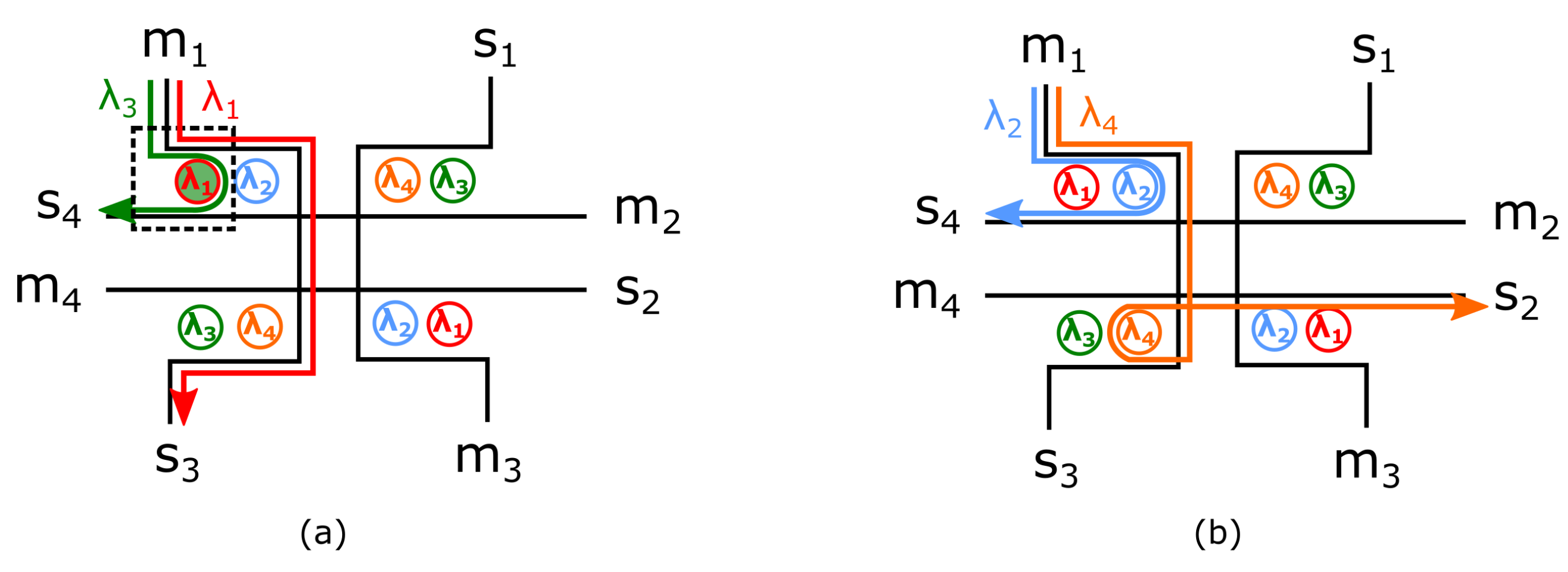
- We propose the first fault-tolerant WRONoC topology, LightR, as an extension of the Light topology [16]. Compared to Light, which reserves only one signal path for each master–slave pair, LightR enhances reliability by providing two independent signal paths to each master–slave pair that requires communication.
- We greatly reduce the MRR usage compared to the state-of-the-art fault-tolerant WRONoC design method.
2. Background
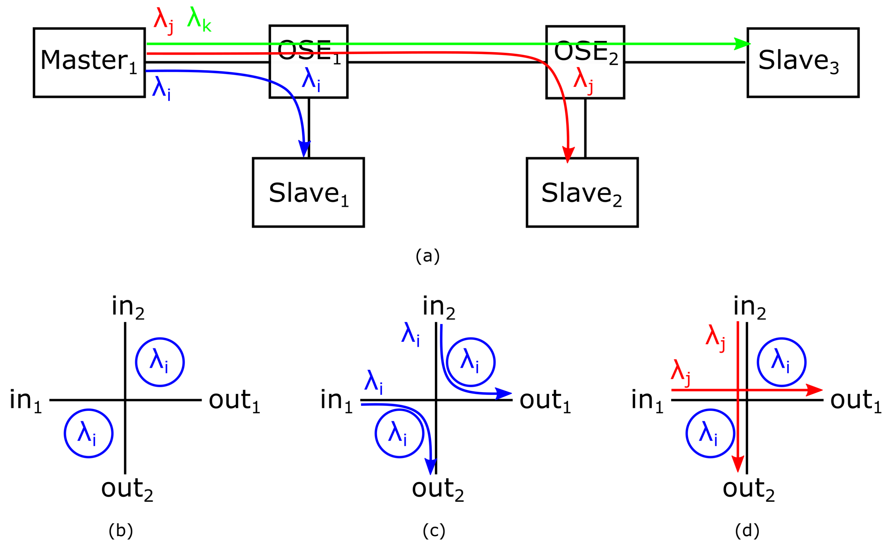
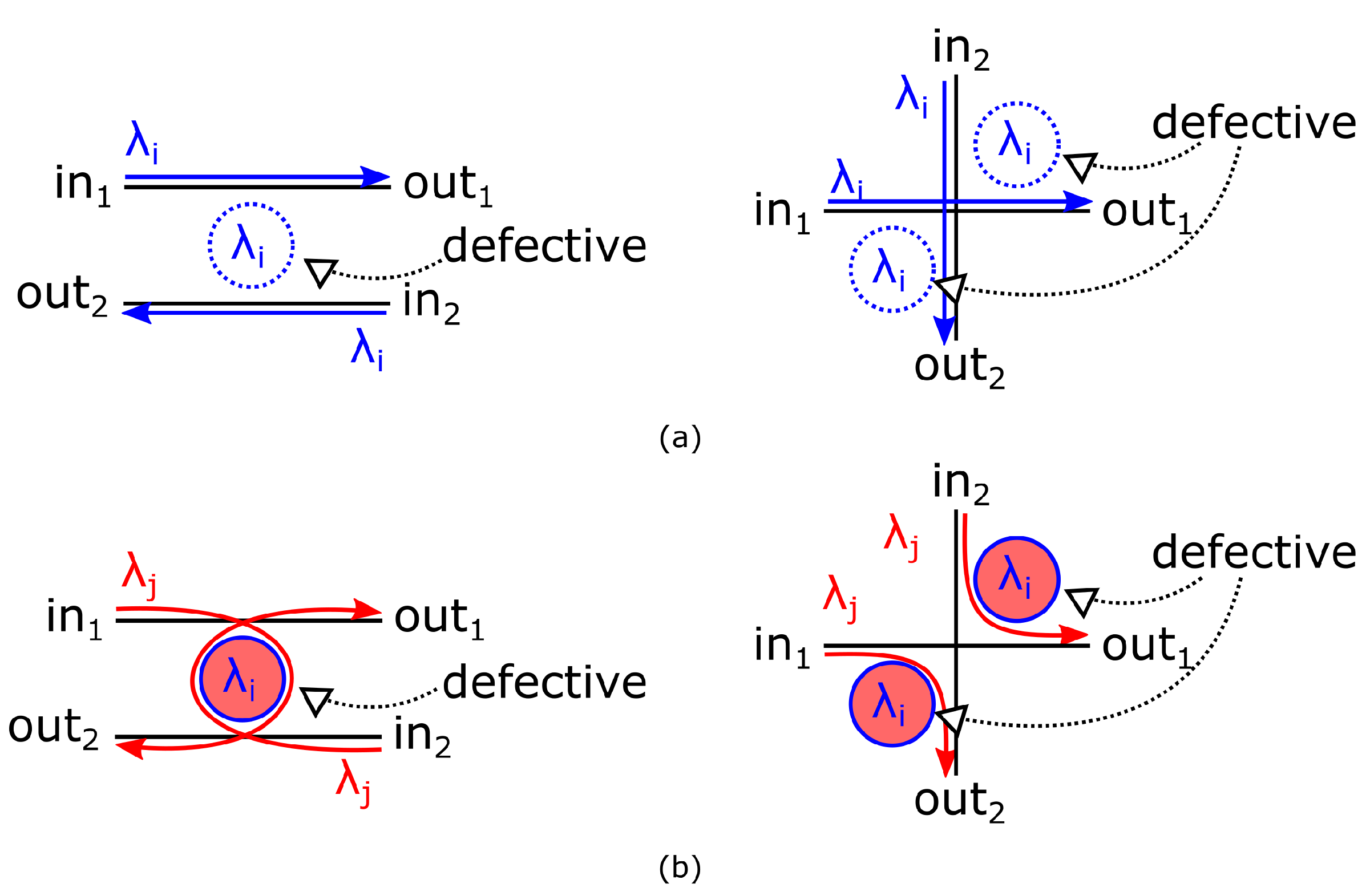
2.1. Parallel Switching Elements
2.2. Performance Factors
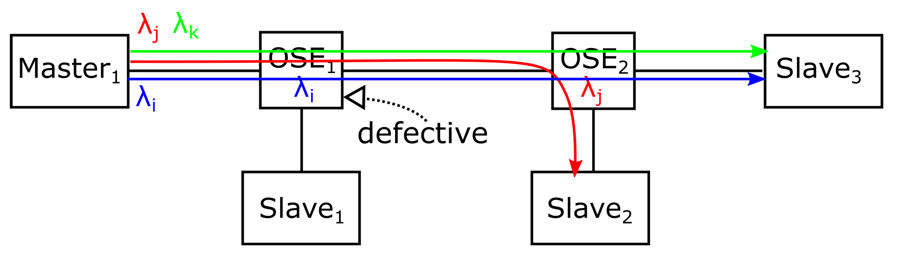
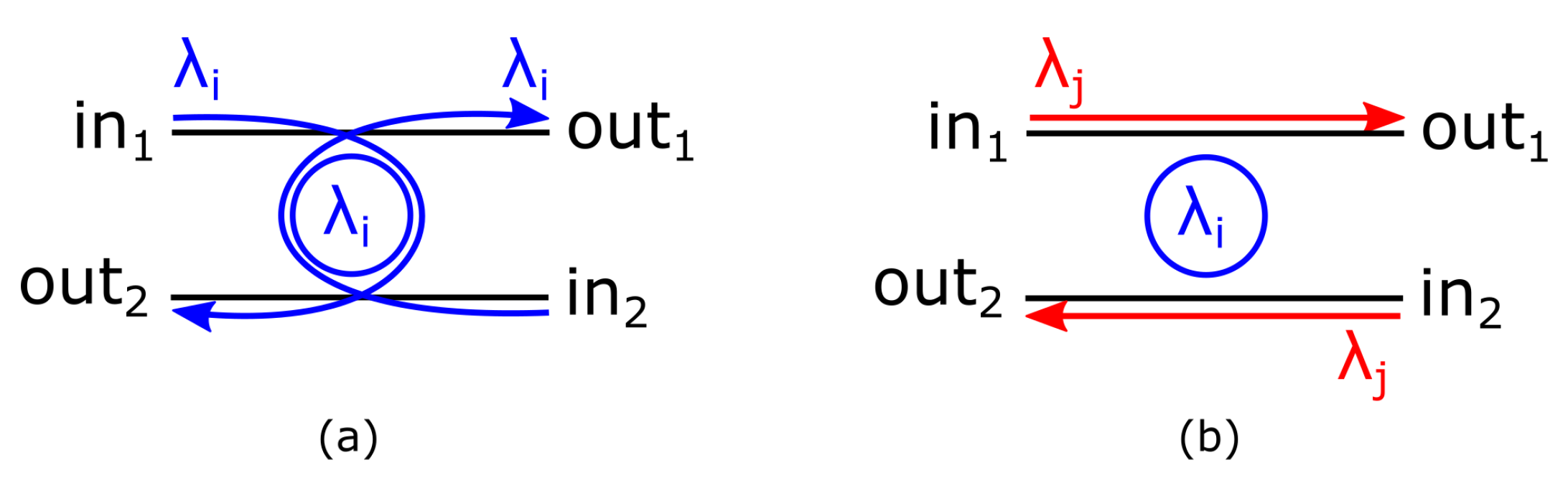
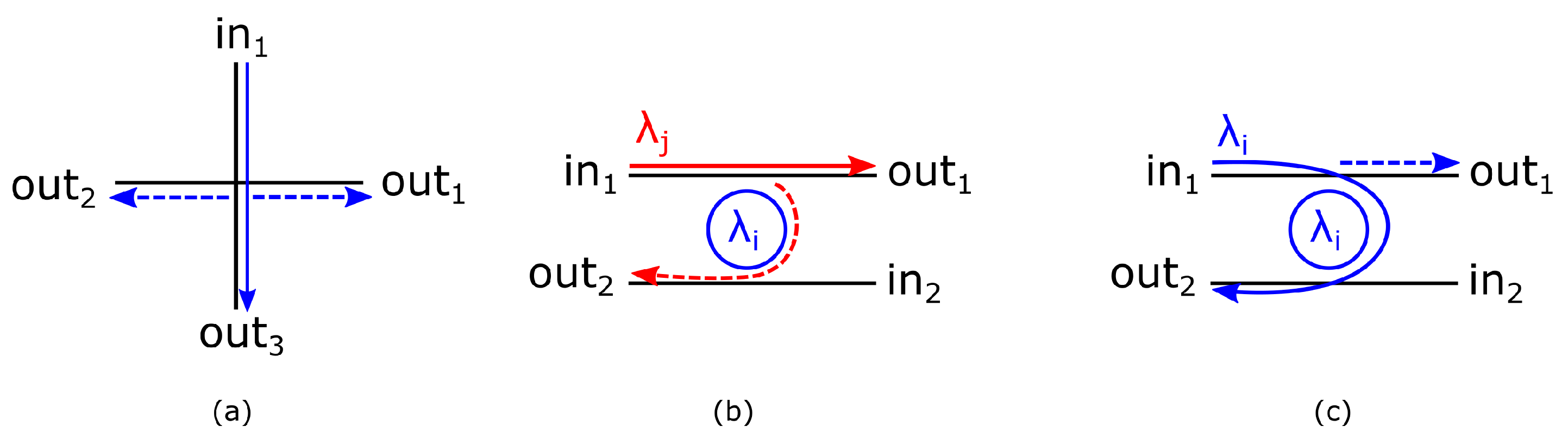
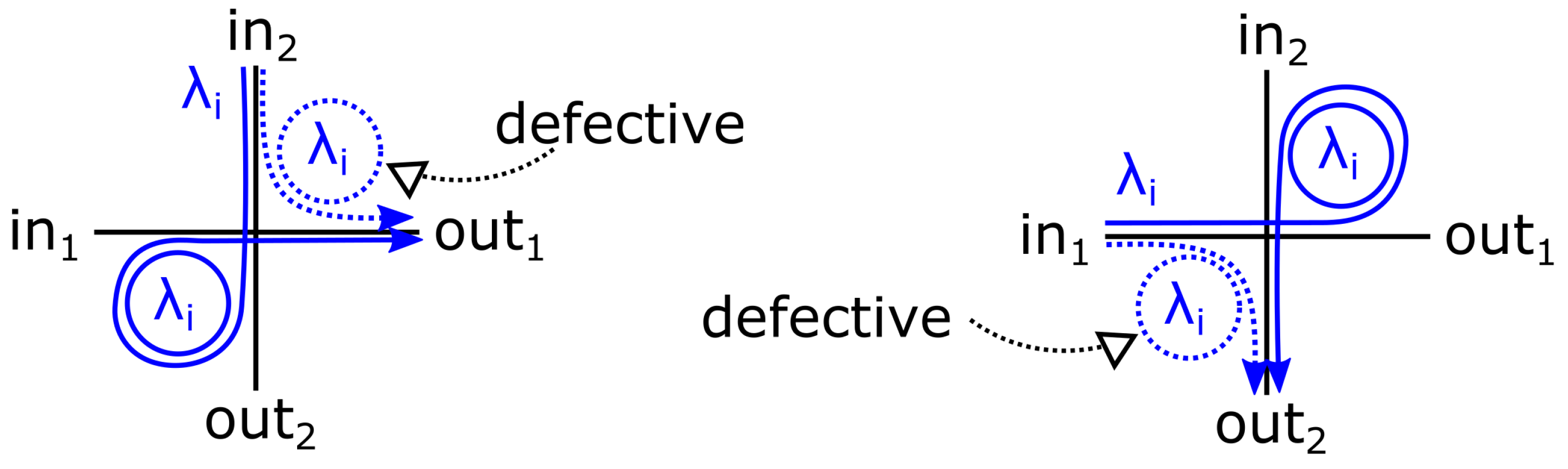
2.3. MRR Faults and Signal Faults
2.4. State-of-the-Art WRONoC Topologies
3. LightR: An Scalable and Fault-Tolerant WRONoC Topology
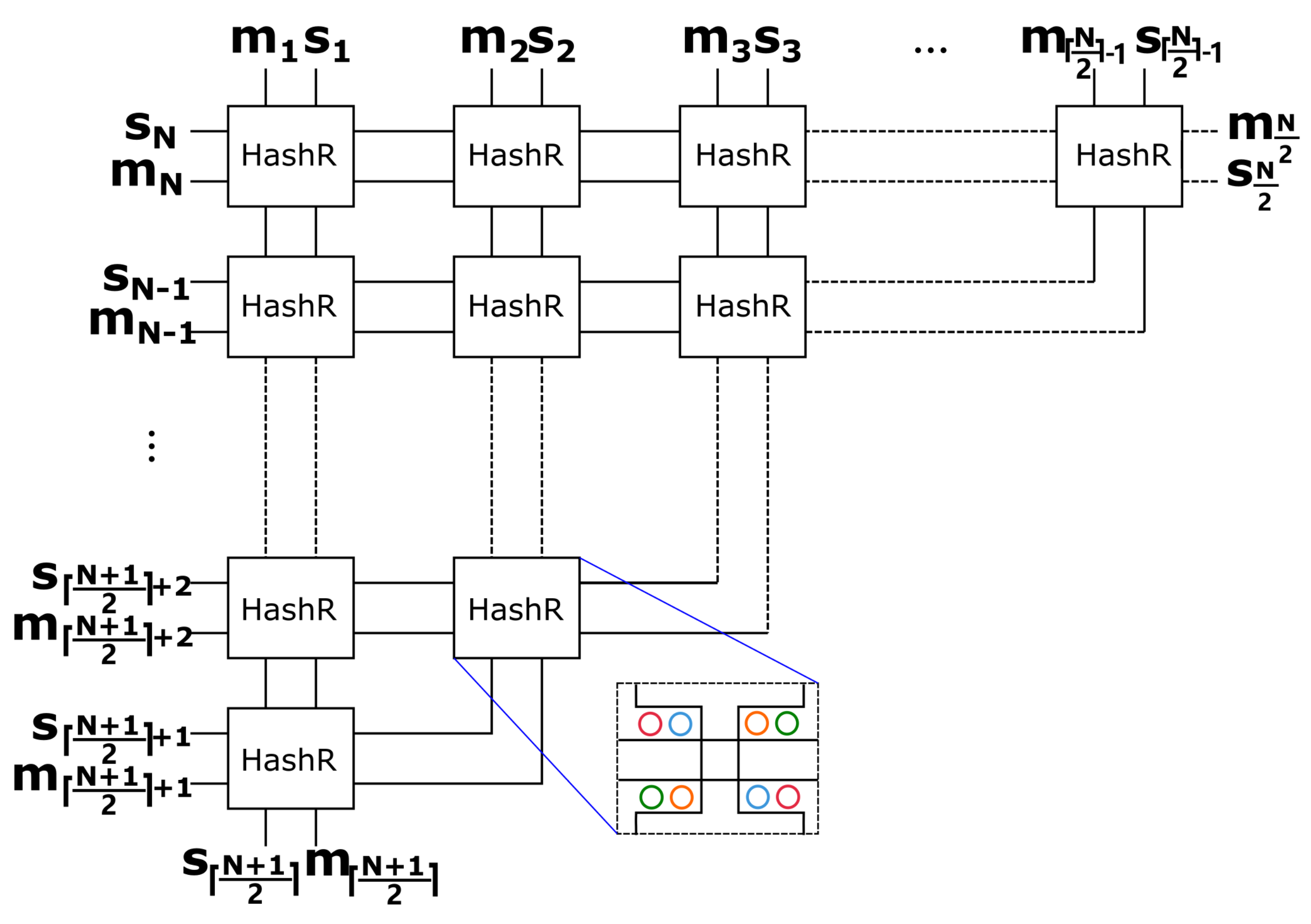
3.1. Logic Scheme of HashR
3.2. Waveguide Connections
- (1)
- Place HashRs horizontally in the k-th row with . Connect the left ports of each HashR with its left neighbor.
- (2)
- Connect the bottom ports of the HashR to its bottom neighbor except for the one at the rightmost end of each row. Connect the bottom ports of the HashR at the rightmost end of each row to its bottom left neighbor.
- (3)
- Connect the upper ports of the HashRs in the first row to the ports , , , , , , …, and , sequentially. If the number of nodes is even, then connect the right ports of the HashR at the rightmost end in the first row to and .
- (4)
- Connect the left ports of the HashRs in the first column to the ports , , , , …, , , , , sequentially. Connect the bottom input and output of the HashR in the last row to and .
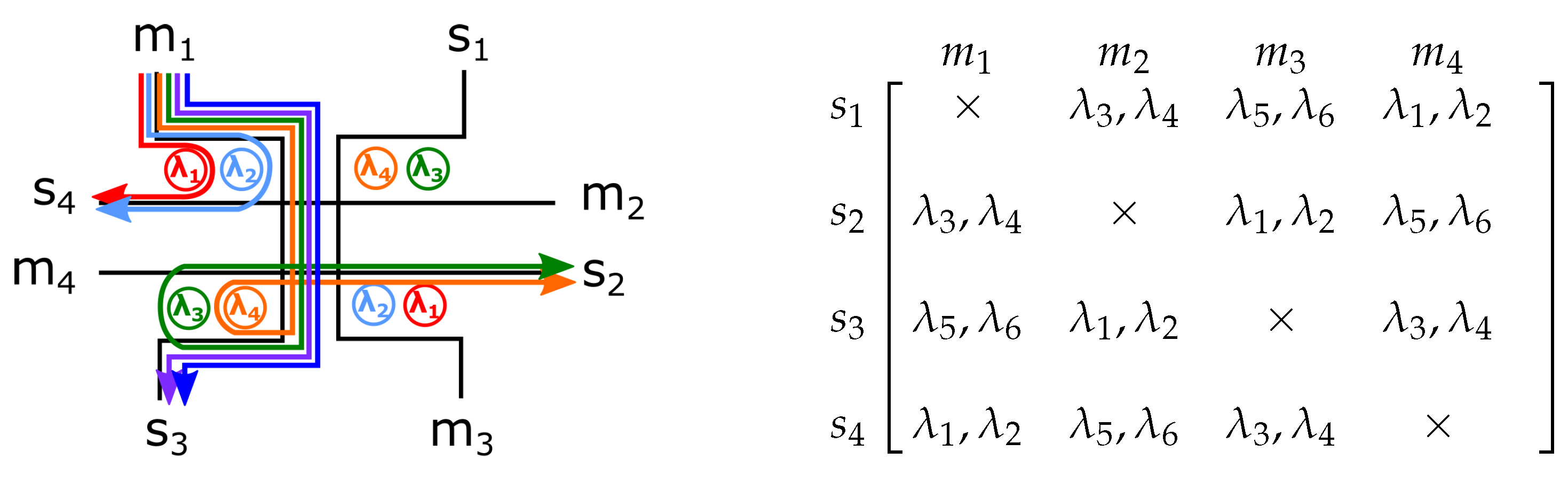
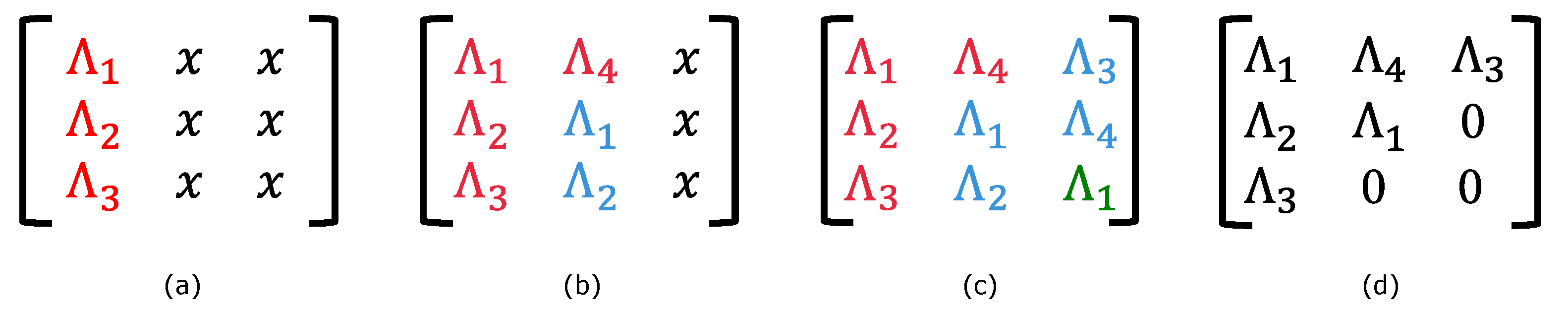
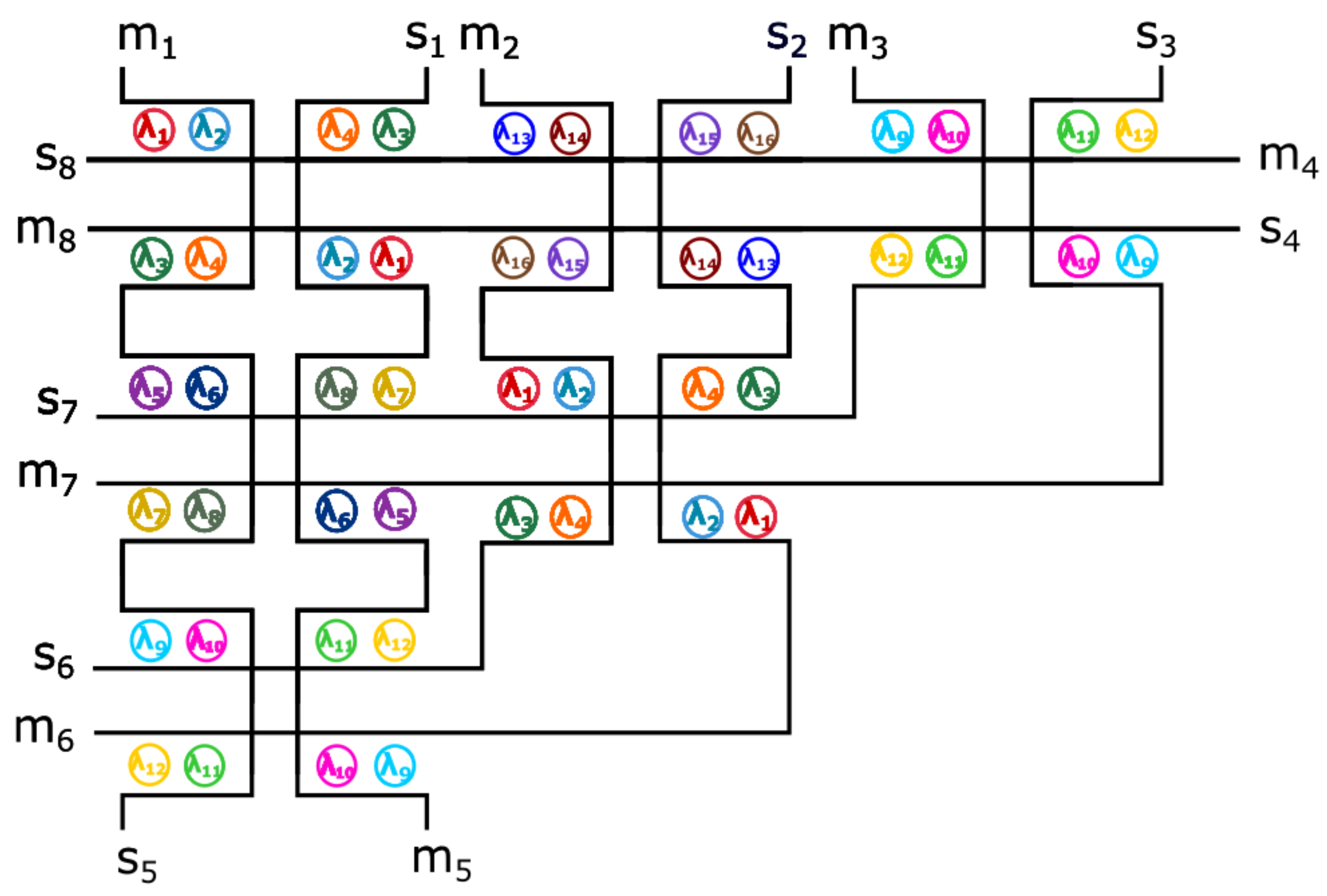
3.3. Wavelength Configuration
4. Experimental Results
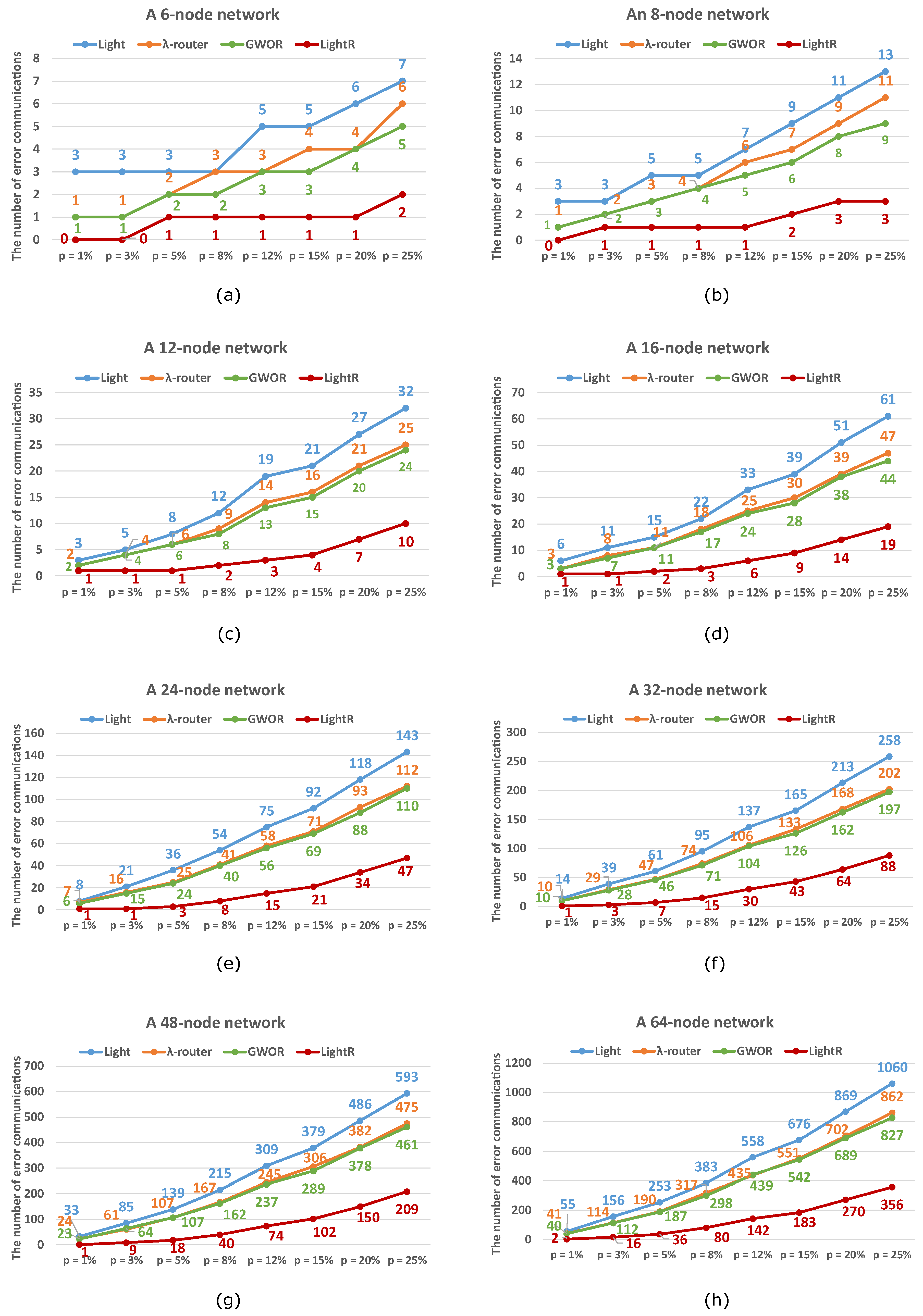
4.1. Comparison with the State-of-the-Art WRONoC Topologies
4.1.1. Discussion: Reliability
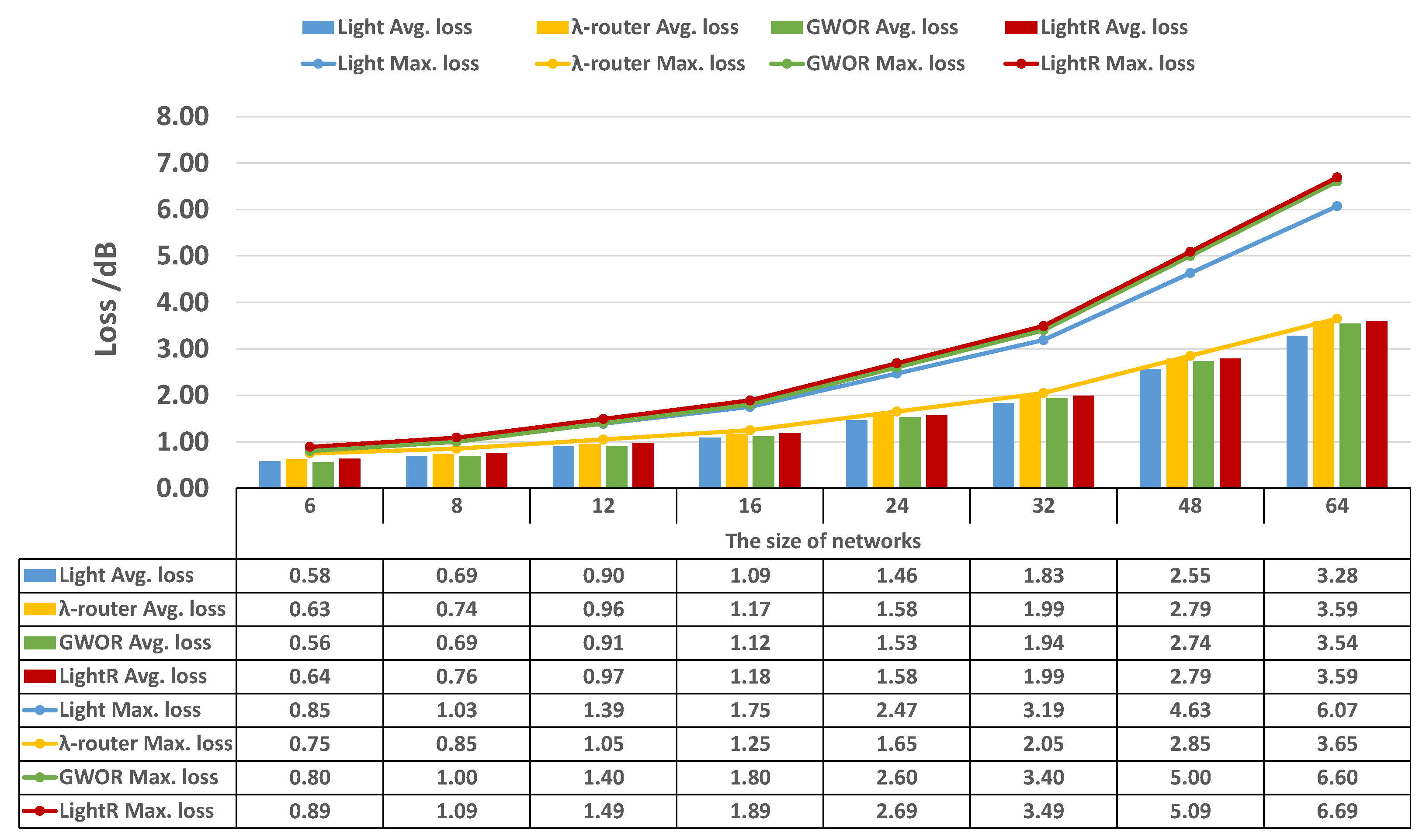
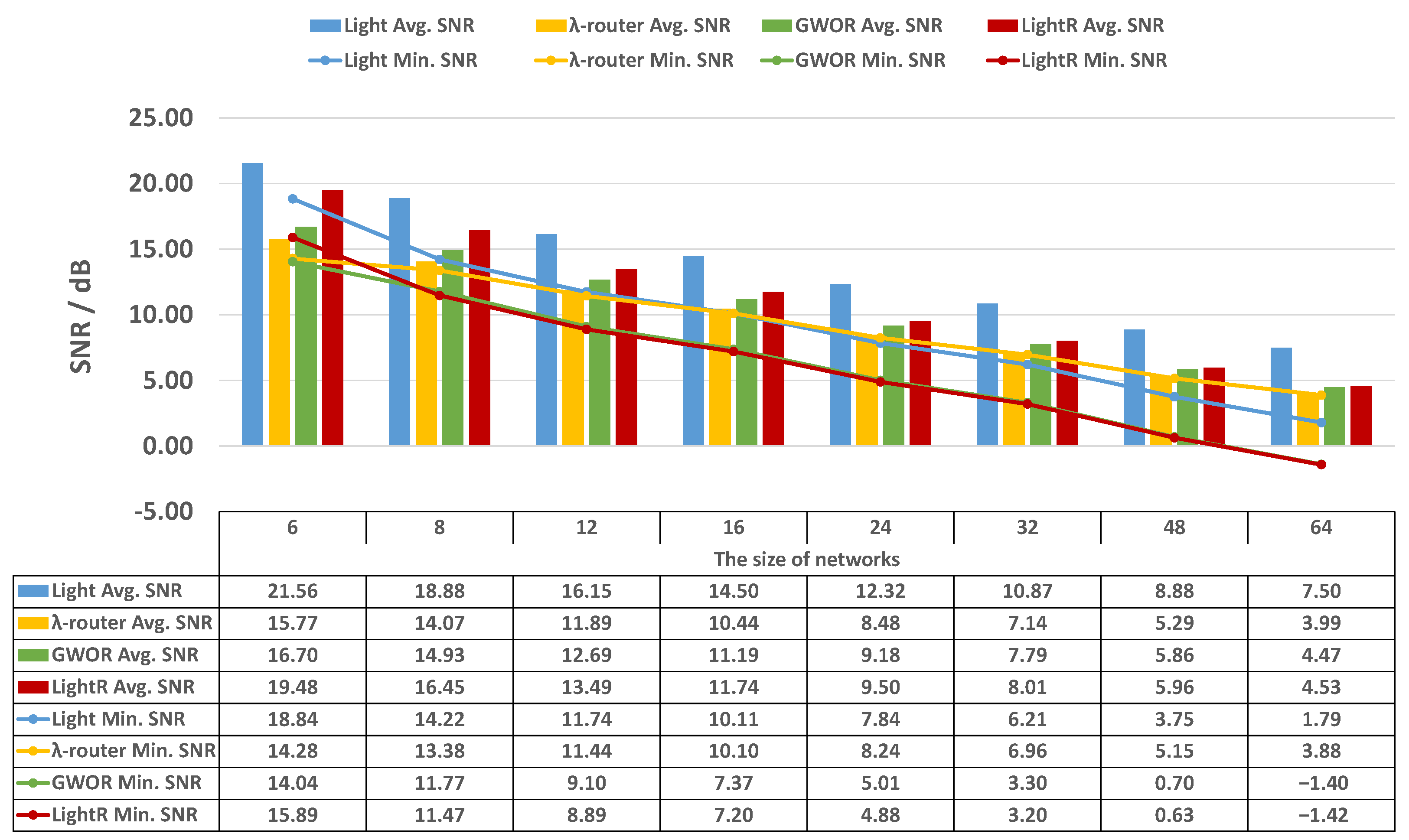
4.1.2. Discussion: MRR Usage, Insertion Loss, and Signal-to-Noise Ratio (SNR)
4.2. Comparison to RobustONoC
5. Conclusions
Author Contributions
Funding
Institutional Review Board Statement
Informed Consent Statement
Data Availability Statement
Conflicts of Interest
Abbreviations
| ONoC | Optical networks-on-chip |
| WDM | Wavelength-division-multiplexing |
| WRONoC | Wavelength-routed optical networks-on-chip |
| OSE | Optical switching element |
| MRR | Microring resonator |
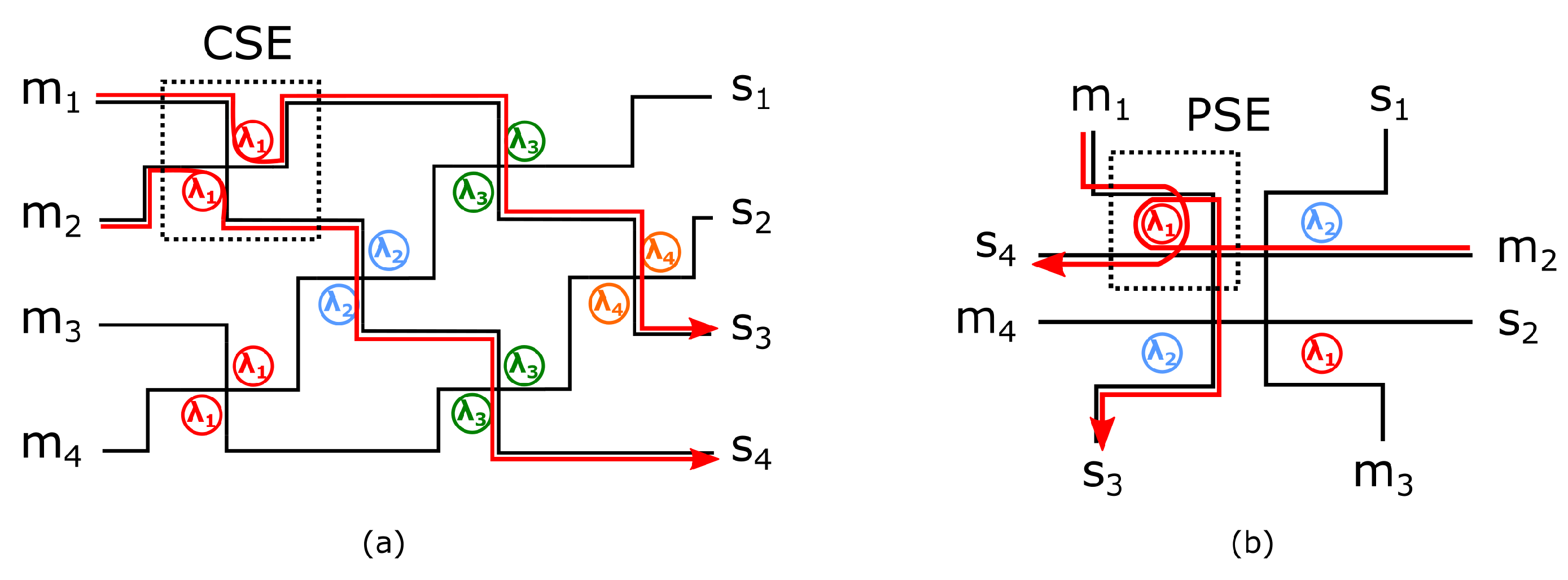
| CSE | Crossing switching element |
| PSE | Parallel switching element |
| SNR | Signal-to-noise ratio |
References
- Vantrease, D.; Schreiber, R.; Monchiero, M.; McLaren, M.; Jouppi, N.P.; Fiorentino, M.; Davis, A.; Binkert, N.; Beausoleil, R.G.; Ahn, J.H. Corona: System Implications of Emerging Nanophotonic Technology. ACM Sigarch Comput. Archit. News 2008, 36, 153–164. [Google Scholar] [CrossRef]
- Tseng, T.M.; Truppel, A.; Li, M.; Nikdast, M.; Schlichtmann, U. Wavelength-Routed Optical NoCs: Design and EDA—State of the Art and Future Directions: Invited Paper. In Proceedings of the 2019 IEEE/ACM International Conference on Computer-Aided Design (ICCAD), Westminster, CO, USA, 4–7 November 2019; pp. 1–6. [Google Scholar] [CrossRef]
- Werner, S.; Navaridas, J.; Luján, M. A Survey on Optical Network-on-Chip Architectures. ACM Comput. Surv. 2017, 50, 1–37. [Google Scholar] [CrossRef]
- Xie, Y.; Nikdast, M.; Xu, J.; Zhang, W.; Li, Q.; Wu, X.; Ye, Y.; Wang, X.; Liu, W. Crosstalk Noise and Bit Error Rate Analysis for Optical Network-on-Chip. In Proceedings of the 47th Design Automation Conference (DAC). Association for Computing Machinery, Anaheim, CA, USA, 13–18 June 2010; pp. 657–660. [Google Scholar] [CrossRef]
- Werner, S.; Navaridas, J.; Luján, M. Amon: An Advanced Mesh-like Optical NoC. In Proceedings of the 2015 IEEE 23rd Annual Symposium on High-Performance Interconnects, Santa Clara, CA, USA, 26–28 August 2015; pp. 52–59. [Google Scholar] [CrossRef]
- Li, M.L.; Tseng, T.M.; Bertozzi, D.; Tala, M.; Schlichtmann, U. CustomTopo: A Topology Generation Method for Application-Specific Wavelength-Routed Optical NoCs. In Proceedings of the 2018 IEEE/ACM International Conference on Computer-Aided Design (ICCAD), New York, NY, USA, 5–8 November 2018; pp. 1–8. [Google Scholar] [CrossRef]
- Li, M.; Tseng, T.M.; Tala, M.; Schlichtmann, U. Maximizing the Communication Parallelism for Wavelength-Routed Optical Networks-On-Chips. In Proceedings of the 2020 Asia and South Pacific Design Automation Conference (ASP-DAC), Beijing, China, 13–16 January 2020; pp. 109–114. [Google Scholar] [CrossRef]
- Truppel, A.; Tseng, T.M.; Bertozzi, D.; Alves, J.C.; Schlichtmann, U. PSION: Combining Logical Topology and Physical Layout Optimization for Wavelength-Routed ONoCs. In Proceedings of the 2019 International Symposium on Physical Design (ISPD), San Francisco, CA, USA, 14–17 April 2019; pp. 49–56. [Google Scholar] [CrossRef]
- Truppel, A.; Tseng, T.M.; Bertozzi, D.; Alves, J.C.; Schlichtmann, U. PSION+: Combining Logical Topology and Physical Layout Optimization for Wavelength-Routed ONoCs. IEEE Trans. Comput. Aided Des. Integr. Circuits Syst. 2020, 39, 5197–5210. [Google Scholar] [CrossRef]
- Truppel, A.; Tseng, T.M.; Schlichtmann, U. PSION 2: Optimizing Physical Layout of Wavelength-Routed ONoCs for Laser Power Reduction. In Proceedings of the 39th International Conference on Computer-Aided Design (ICCAD), Virtual, 2–5 November 2020; Association for Computing Machinery: New York, NY, USA, 2020. [Google Scholar] [CrossRef]
- Zheng, Z.; Li, M.; Tseng, T.M.; Schlichtmann, U. ToPro: A Topology Projector and Waveguide Router for Wavelength-Routed Optical Networks-on-Chip. In Proceedings of the 2021 IEEE/ACM International Conference On Computer Aided Design (ICCAD), Munich, Germany, 1–4 November 2021; pp. 1–9. [Google Scholar] [CrossRef]
- Meyer, M.C.; Ahmed, A.B.; Okuyama, Y.; Abdallah, A.B. FTTDOR: Microring Fault-resilient Optical Router for Reliable Optical Network-on-Chip Systems. In Proceedings of the 2015 IEEE 9th International Symposium on Embedded Multicore/Many-core Systems-on-Chip, Turin, Italy, 23–25 September 2015; pp. 227–234. [Google Scholar] [CrossRef]
- Nitta, C.J.; Farrens, M.K.; Akella, V. Resilient Microring Resonator Based Photonic Networks. In Proceedings of the 44th Annual IEEE/ACM International Symposium on Microarchitecture, Porto Alegre, Brazil, 3–7 December 2011; pp. 95–104. [Google Scholar] [CrossRef]
- Meyer, M.; Abdallah, A.B. Fault-tolerant Photonic Network-on-Chip. In Photonic Interconnects for Computing Systems: Understanding and Pushing Design Challenges; River Publishers: Aalborg, Denmark, 2017; pp. 281–318. [Google Scholar]
- Chuang, Y.K.; Zhong, Y.; Cheng, Y.H.; Yu, B.Y.; Fang, S.Y.; Li, B.; Schlichtmann, U. RobustONoC: Fault-Tolerant Optical Networks-on-Chip with Path Backup and Signal Reflection. In Proceedings of the 2021 22nd International Symposium on Quality Electronic Design (ISQED), Santa Clara, CA, USA, 7–9 April 2021; pp. 67–72. [Google Scholar] [CrossRef]
- Zheng, Z.; Li, M.; Tseng, T.M.; Schlichtmann, U. Light: A Scalable and Efficient Wavelength-Routed Optical Networks-On-Chip Topology. In Proceedings of the 2021 Asia and South Pacific Design Automation Conference (ASP-DAC), Tokyo, Japan, 18–21 January 2021; pp. 568–573. [Google Scholar] [CrossRef]
- Briere, M.; Girodias, B.; Bouchebaba, Y.; Nicolescu, G.; Mieyeville, F.; Gaffiot, F.; O’Connor, I. System Level Assessment of an Optical NoC in an MPSoC Platform. In Proceedings of the 2007 Design, Automation Test in Europe Conference Exhibition (DATE), Nice, France, 16–20 April 2007; pp. 1–6. [Google Scholar] [CrossRef]
- Tan, X.; Yang, M.; Zhang, L.; Jiang, Y.; Yang, J. On a Scalable, Non-Blocking Optical Router for Photonic Networks-on-Chip Designs. In Proceedings of the 2011 Symposium on Photonics and Optoelectronics (SOPO), Wuhan, China, 16–18 May 2011; pp. 1–4. [Google Scholar] [CrossRef]
- Nikdast, M.; Xu, J.; Duong, L.H.K.; Wu, X.; Wang, X.; Wang, Z.; Wang, Z.; Yang, P.; Ye, Y.; Hao, Q. Crosstalk Noise in WDM-Based Optical Networks-on-Chip: A Formal Study and Comparison. IEEE Trans. Very Large Scale Integr. Vlsi Syst. 2015, 23, 2552–2565. [Google Scholar] [CrossRef]
- Zheng, Z.; Li, M.; Tseng, T.M.; Schlichtmann, U. XRing: A Crosstalk-Aware Synthesis Method for Wavelength-Routed Optical Ring Routers. In Proceedings of the 2023 Design, Automation Test in Europe Conference Exhibition (DATE), Antwerp, Belgium, 17–19 April 2023; pp. 1–9. [Google Scholar]
- Nitta, C.; Farrens, M.; Akella, V. Addressing system-level trimming issues in on-chip nanophotonic networks. In Proceedings of the 2011 IEEE 17th International Symposium on High Performance Computer Architecture, San Antonio, TX, USA, 12–16 February 2011; pp. 122–131. [Google Scholar] [CrossRef]
- Bogaerts, W.; De Heyn, P.; Van Vaerenbergh, T.; De Vos, K.; Kumar Selvaraja, S.; Claes, T.; Dumon, P.; Bienstman, P.; Van Thourhout, D.; Baets, R. Silicon microring resonators. Laser Photonics Rev. 2012, 6, 47–73. [Google Scholar] [CrossRef]
- Ramini, L.; Grani, P.; Bartolini, S.; Bertozzi, D. Contrasting wavelength-routed optical NoC topologies for power-efficient 3d-stacked multicore processors using physical-layer analysis. In Proceedings of the 2013 Design, Automation Test in Europe Conference Exhibition (DATE), Grenoble, France, 18–22 March 2013; pp. 1589–1594. [Google Scholar] [CrossRef]
- Xiao, M.; Tseng, T.M.; Schlichtmann, U. FAST: A Fast Automatic Sweeping Topology Customization Method for Application-Specific Wavelength-Routed Optical NoCs. In Proceedings of the 2021 Design, Automation Test in Europe Conference Exhibition (DATE), Grenoble, France, 1–5 February 2021; pp. 1651–1656. [Google Scholar] [CrossRef]


| × | , , | |||||||
| × | , | , | , | |||||
| × | , , | |||||||
| , | × | , | , | |||||
| , , | × | |||||||
| , | , | × | , | |||||
| , , | × | |||||||
| , | , | , | × |
| The Number of Nodes | ||||||||
|---|---|---|---|---|---|---|---|---|
| N = 6 | N = 8 | N = 12 | N = 16 | N = 24 | N = 32 | N = 48 | N = 64 | |
| Light | 12 | 24 | 60 | 112 | 240 | 480 | 1104 | 1984 |
| -router | 30 | 56 | 132 | 240 | 552 | 992 | 2256 | 4032 |
| GWOR | 24 | 48 | 120 | 224 | 480 | 960 | 2208 | 3968 |
| LightR | 24 | 48 | 120 | 224 | 480 | 960 | 2208 | 3968 |
| Insertion Loss Parameters | Crosstalk Noise Parameters | |||
|---|---|---|---|---|
| Drop loss | Through loss | Crossing loss | Crosstalk per MRR | Crosstalk per crossing |
| db | db | db | 25 db | 40 db |
Disclaimer/Publisher’s Note: The statements, opinions and data contained in all publications are solely those of the individual author(s) and contributor(s) and not of MDPI and/or the editor(s). MDPI and/or the editor(s) disclaim responsibility for any injury to people or property resulting from any ideas, methods, instructions or products referred to in the content. |
© 2023 by the authors. Licensee MDPI, Basel, Switzerland. This article is an open access article distributed under the terms and conditions of the Creative Commons Attribution (CC BY) license (https://creativecommons.org/licenses/by/4.0/).
Share and Cite
Zheng, Z.; Li, M.; Tseng, T.-M.; Schlichtmann, U. LightR: A Fault-Tolerant Wavelength-Routed Optical Networks-on-Chip Topology. Appl. Sci. 2023, 13, 8871. https://doi.org/10.3390/app13158871
Zheng Z, Li M, Tseng T-M, Schlichtmann U. LightR: A Fault-Tolerant Wavelength-Routed Optical Networks-on-Chip Topology. Applied Sciences. 2023; 13(15):8871. https://doi.org/10.3390/app13158871
Chicago/Turabian StyleZheng, Zhidan, Mengchu Li, Tsun-Ming Tseng, and Ulf Schlichtmann. 2023. "LightR: A Fault-Tolerant Wavelength-Routed Optical Networks-on-Chip Topology" Applied Sciences 13, no. 15: 8871. https://doi.org/10.3390/app13158871
APA StyleZheng, Z., Li, M., Tseng, T.-M., & Schlichtmann, U. (2023). LightR: A Fault-Tolerant Wavelength-Routed Optical Networks-on-Chip Topology. Applied Sciences, 13(15), 8871. https://doi.org/10.3390/app13158871