Abstract
Tensegrity structures are prestressed and self-stable pin-connected frameworks built up mainly from two kind of elements, in compression (bars) and in tension (tendons). It has been 75 years since the first official appearance of tensegrity, although the present paper includes proof that states that they are in fact more than 100 years old. Throughout these years, tensegrity structures have been capturing engineers’, architects’ and artists’ attention with their peculiar properties. In the last decade, new applications have been found based on tensegrity, although there are not any compilations about them. This paper aims to fill this gap by giving an overview of all the recent real applications that tensegrity has had during its short life, at the same time exposing its potential in all the fields it has contributed to (AEC, robotics, space, etc.) The methodology for performing this review has been revisiting the most relevant publications in several scientific databases. This has led to a new discovery: the first cable-dome by Snelson. As a conclusion, tensegrity has been providing useful solutions to previous problems since they have appeared, but their potential can still grow in an exponential way due to the new technologies and discoveries of the last decade.
1. Introduction
Tensegrity is a principle that is said to have been discovered for the first time about 75 years ago, although some authors claim that it was created by Karl Ioganson more than 100 years ago [1]. In fact, the authors of the present work have found a picture from 1921 (Figure 1) where Karl Ioganson’s tensegrity prototypes can be seen with the first example of a Simplex [2,3], which was patented some decades later.
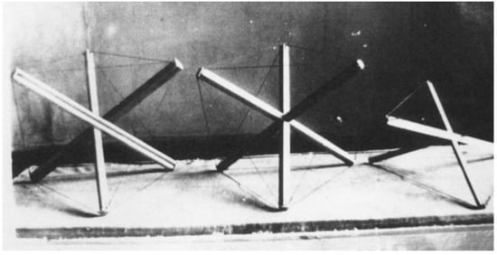
Figure 1.
Karl Ioganson’s tensegrity prototypes showing the first example of a Simplex (figure on the left-hand side) in 1921. Reprinted with permission from Refs. [2,3].
Tensegrity governs the behavior of many structures within the engineering scope [4]. Throughout the years, many definitions have been given to this principle. On an informal basis, tensegrities are prestressed and self-stable pin-connected frameworks built up from two kinds of elements, bars and tendons [5]. Bars, also called struts, will always carry compression, whereas tendons (cables, wires, strings or membranes) can only work under tension. The former are usually made of wood, bamboo or metal (steel, aluminum, titanium, etc.), while the latter can be built from steel wires, elastic cords and bands, ropes, elastic membranes, adaptive fabrics, etc.
One of the precursors of tensegrity, Richard Buckminster Fuller, defined tensegrity as “islands of compression in an ocean of tension”. In fact, what he said on a TV interview was that “what nature has is islands of spherical compression in a sea of comprehensive tension” [6]. As is well known, he was responsible for coining these kinds of structures as “Tensegrity” resulting from the contraction of the two words “tensional” and “integrity” [7].
One of the problems that we have come across when collecting all the information for this review is the misperception of the concept. The term “tensegrity” has been used to refer to structures composed of compressed and tensioned elements regardless of their self-stress condition. In fact, most bar–tendon configurations that one might conceive are not in equilibrium, and once constructed would collapse and change their shape unless they are sustained by external supports. Therefore, the global stability needs to be checked, which is often ignored, and, as a consequence, leads to structures that cannot remain stable once they have been realized [8,9]. That is why only prestressed bar–cable configurations in stable equilibrium can be called tensegrity structures [10,11]. Another distinguishing characteristic of these structures, in its purest conception, is that two compressed elements cannot be connected one to another. If two bars join at the same node, it will be considered as a k = 2 tensegrity structure; if 3 bars meet, k = 3 tensegrity, and so on [12].
Since their “official” discovery in the late 1940s by Kenneth Snelson, tensegrity structures have captured the attention of many engineers, architects, and artists due to their unique advantages and peculiar properties, one of which is that the bars do not touch each other [13]. Some of their singular features are:
- Self-equilibrium: the stability of the structure depends on its own configuration and topology, not on external supports.
- Lightweight and efficiency: tensegrity structures use longitudinal members arranged in an unusual pattern to achieve strength with small mass.
- Deployability: due to the fact that the compressed members are connected by ball joints, they are easy to fold.
- Small compression volume: the structure has a certain degree of compliance in all degrees of freedom.
- Low control cost [5,10].
Due to all these advantages, tensegrity-based structures have been offering a very interesting field of study in a wide range of engineering scopes.
However, these unique structures have struggled when trying to make their way into all the different architecture and engineering fields. Some of the difficulties they have had to face include a problem of bar congestion—when some designs become larger, the struts start colliding with each other [14]. This same author stated their high deflections and low material efficiency, when compared with other conventional structures with a rigid geometry. Another limiting fact is their fabrication complexity because spherical and domical structures are complex and this can lead to problems in production and assembling processes. In order to support critical loads, the pre-stress forces should be very high, which could create strut buckling and be difficult to implement in larger-size constructions [15]. In addition, for many years, there was a lack of design and analysis techniques for these structures, given that the existing calculus and form-finding methods were inadequate, slow and powerless, which has been solved by the current computational tools and methods: analytical, dynamic relaxation, force density, energy, reduced coordinates, group theory, algebraic, evolutionary, finite element, Monte Carlo, genetic algorithms, reference joints of symmetry orbits, etc. [16]. Lately, structure calculations can benefit from the development of tribo-fatigue as the new section of mechanics, the science unifying fatigue, friction and wear [17].
The authors of the present paper have found an important gap in the literature that they would like to fill. Up to now, there have not been many reviews about tensegrity structures. Some of them have been devoted to structural analysis, either static [18] or dynamic [19], and another one has focused on tensegrity structures-based robots [20]. There are also some titles with the word “review” [21] that are not really an analysis of the state of the art of these kind of structures. Sultan’s recompilation [22] should be taken into consideration, although this work was written 14 years ago and there are some interesting innovations that have arisen in the last decade; furthermore, his review is more focused on historical facts, form-finding, calculation methods and control issues, rather than on real built applications.
Therefore, we have performed an exhaustive search to gather the most relevant applications of tensegrity structures. The methodology for performing this review has been based on revisiting the most important publications in several scientific databases (Web of Science, Scopus, Engineering Village, IeeeXplore and Google Scholar). The main search was performed by looking for works including the terms “tensegrity” AND “application” AND (“built” OR “constructed”) AND (“robotics” OR “anatomy” OR “architecture” OR “engineering” OR “space”), as well as their translations in French and Spanish. Many of these publications led to others by searching for other interesting links in their reference lists. Finally, more than 500 papers have been revised, although approximately 20% of them were relevant for the purpose of the present review.
Thus, the aim of this article is to show all the real possibilities, actually built, that these structures have been opening up over the last years. We have not included many theoretical proposals that have been designed but never brought to reality. As the reader will see in the following pages, tensegrities have become innovative solutions to new or even early engineering issues from the architecture, civil engineering or robotics to medicine scope. By showing all the applications and the different areas that they have been involved in, we intend to declare their potential and encourage their inclusion in other areas or with different purposes.
The structure of this paper is as follows: an introduction to tensegrity structures, as well as their advantages and problems, and the methodology carried out in this research, are briefly reported in the present section. Then, Section 2 introduces the applications for AEC, which includes some of the fields explained in the title: architecture and engineering related to the construction field. Spatial engineering has been considered relevant enough for being developed and explained in an independent section, the third one. Also closely related with engineering, Section 4 deals with all the applications regarding robotics and controlling. The fifth part of this communication is the shortest, but not the least important, due to its huge future potential: applications to human anatomy, prosthetics and biotechnology. The paper closes in Section 6 with the main conclusions and some insights about the exponential evolution of this line of research as well as its distribution worldwide.
2. Applications for AEC
AEC stands for Architecture, Engineering and Construction. Architecture was the first field in which tensegrity structures were introduced, probably given that one of its precursors (Buckminster Fuller) was indeed an architect. He devoted his efforts to finding applications of his tensegrity structures in domes, towers and buildings.
2.1. Towers
Although towers and masts are very similar structural typologies, we will devote this section to towers in the field of AEC. At the same time, we will talk about masts in the next section dedicated to space applications.
As it is well known, Kenneth Snelson was the precursor of the “continuous tension—discontinuous compression” towers, whose patent of 1960 [23] already included some towers and vertical structures (Figure 2a,b). Most of Snelson’s towers are built from the juxtaposition of basic tensegrity T-prisms (e.g., the Simplex), one on top of the other. The Needle Tower (Figure 2d), built in 1968, with 18 m of height, is the most popular example, although the artist built several masts along his career.
Emmerich made his contribution to the area of masts as well. His 1963 patent [24] showed a tensegrity mast built from five modules, each of them having three struts (Figure 2c).
Another paradigmatic example of these typologies is the tower of Rostock (Figure 2e), built for the International Garden Exhibition in Rostock (IGA 2003). This k = 2 structure was designed by Mike Schlaich and consists of six twist modules of 8.3 m height, which assembled the form of the 62.3 m tower [25]. Its typology is probably inspired in Snelson’s “Zig-zag tower” of 1997 [26,27].
Fuller also developed a tetrahedral tensegrity mast as the one shown in Figure 2f. This particular example was for the MoMa exhibition in 1959 [28]. The elementary cell of this mast was latter called “V-Expander” by Motro.
Later, in the Masts section, tensegrity-based masts will be mentioned and exposed. These masts are used for space missions, that is the main reason why we do not include them in this chapter dedicated to towers in the AEC sector.

Figure 2.
Different examples of tensegrity towers. (a,b) Patents by Snelson. (c) Patent by Emmerich. (d) Needle Tower by Snelson (image by Saku Takakusaki). (e) Rostock Tower (image from https://www.sbp.de/en/project/tower-at-the-fair-of-rostock/, (accessed on 15 September 2022)). (f) Tensegrity mast by Fuller [29].

2.2. Domes and Roofs
Several tensegrity-based domes have been proposed throughout the tensegrity history. This is probably because it is simple to obtain a sphere from a polyhedral tensegrity structure such as a regular dodecahedron or icosahedron.
Probably the first examples of this kind of tensegrity structure were the two tensegrity domes constructed by Fuller in 1953 in Princeton University and University of Minnesota [30]. The former was a 40-foot-diameter 90-strut tensegrity enenticontahedron and the latter was a 40-foot-diameter 270-strut tensegrity hemisphere (Figure 3a). Even if it was a milestone in tensegrity history, it lacked stability due to the absence of triangulation in the connecting cables. Therefore, the application of tensegrity domes to architecture was not successful at that stage.
Fuller also developed and patented the so-called Aspension Dome (Figure 3b), [31]. The design was based on the one of a bicycle wheel, preconizing a specific type of structure called cable dome, in which the radial cables connect an outer compression ring to an inner tension ring. As he explains in his patent:
“…a catenary suspension system can be converted into an arched structure of domical or polygonal form. By breaking up the suspension cables into increments suspending an ascending series of polygonal or circular frames stepped upwardly one within another, altitude is gained, replacing the catenary sag of the bridge cables with a rising, arched, suspension system” [31].

Figure 3.
(a) Tensegrity Dome by Fuller at the University of Minessota, 1953 (photo from [30]). (b) Top and front view of Fuller’s Aspension Dome (photo from [32]).
Figure 3.
(a) Tensegrity Dome by Fuller at the University of Minessota, 1953 (photo from [30]). (b) Top and front view of Fuller’s Aspension Dome (photo from [32]).

The Aspension Dome was used as an inspiration for the Olympic Fencing and Gymnastic Arena in Seoul (Republic of Korea) (Figure 4a). This stadium’s roof was built by David Geiger in 1988. The radial cables connecting the inner and the outer ring in Fuller’s design formed triangles, whereas in Geiger’s design, these belong to vertical planes passing through the central symmetry axis of the whole structure.
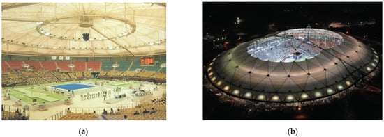
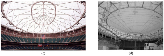
Figure 4.
(a) Geiger’s 1988 Olympic Arena in Seoul (photo from [33]). (b) Opening of completed La Plata Stadium [34] (image from https://commons.wikimedia.org/wiki/File:Estadio_Único_Ciudad_de_La_Plata.jpg, (accessed on 15 September 2022)). (c) Georgia Dome in Atlanta (from https://www.birdair.com/birdair-portfolio/georgia-dome/, (accessed on 15 September 2022)). (d) World Cycling Center dome [35] (Image courtesy of André Oribasi).
These two examples, as well as others inspired by Kiewitt’s works [36], belong to the category of the cable dome, which has been widely used along the last 5 decades [36,37]. However, the cable dome does not fully participate in the tensegrity principle because it can only work in co-function with an outer compressed ring beam to form a truly self-stressed, self-equilibrium system [38]. Some authors do not consider them real tensegrity systems because the boundary is delimited by a compressed element (the peripheral concrete beam), instead of components in tension (wires, tendons or membranes).
Based on these ideas of domes, some tensegrity roofs have been built over the last years. One example is the Stadium of the City of La Plata [34] designed in the late 1990s (Figure 4b). This roof was built from a tensegrity system entailing four elements: a cable net forming triangles, triangulated cables in suspension, hoop cables, and rigid vertical posts. The La Plata design is an application of the patented tensegrity structure system first developed for use at the Georgia Dome in Atlanta (Figure 4c). In fact, the structural engineers were Weidlinger Associates, who also worked on the analysis of this dome. However, as already said, these kinds of roofs cannot be considered pure tensegrity roofs due to the metallic external ring (in compression) that supports the structure.
Something similar happens with the World Cycling Centre in Aigle in (Switzerland) (Figure 4d) designed by Oribasi and Paronesso [35]. The cycling track has a 200 m length and it is dimensioned to receive 700 people. The roof is built upon a pneumatic membrane, an elliptical ring surrounding the structure and an inner bi-pyramidal tensegrity structure. The tensegrity structure is supported by 28 struts that are joint by prestressed diagonal cables, placed through the perimeter of the arena.
However, the authors of the present communication have discovered that this cable dome typology had already been designed previously by Kenneth Snelson in 1949 in the Summer Institute, at Black Mountain College. In one of the pictures of the Western Regional Archives (Figure 5), Snelson can be seen building some models, in the background of this photo on the right-hand side, a cable dome can be seen precisely (also called wire wheel dome) modelled inside a bicycle wheel.
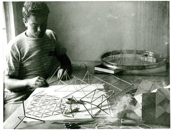
Figure 5.
Kenneth Snelson with the first cable dome or wire wheel dome (highlighted in yellow), in 1949 at the Summer Institute, Black Mountain College (Image courtesy of Western Regional Archives).
In order to substitute the external ring in compression, Peña [39] proposed the use of a tensegrity torus, so that the whole dome was in self-equilibrium and did not depend on external supports. Additionally, she replaced the conventional cables by a set of membranes in tension with two purposes: prestressing the structure and serving as a cladding for covering the roof (Figure 6).
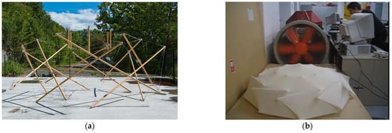
Figure 6.
(a) Prototype for a tensegrity roof structure made of cables and bars [39]. (b) Wind turbine test on a smaller prototype made of textile membranes and bars [40]. (Images courtesy of Diana Peña).
Some other prototypes of tensile tensegrity structures were proposed by Gupta et al. [41], a knit tensegrity shell composed by an elastic membrane and bamboo struts to make canopies appropriate to the warm, humid climate of Singapore (Figure 7a). Another example of canopies made with bamboo and tensile membranes is the one by Mortera Aguilar [42], although in this case it was composed by the juxtaposition of expanded cuboctahedrons (Figure 7b).
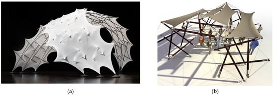
Figure 7.
(a) Prototype of a knit tensegrity shell with membrane and bamboo struts. Reprinted with permission from Ref. [41]. (b) Tensegrity canopy composed by expanded cuboctahedrons Reprinted with permission from Ref. [42].
However, even if these structures look like very modern and ground-breaking, there were some precedents in the 1980s. In his book, Eekhout [43] refers to some tensegrity structures built by means of metallic poles, cables and membranes, to configure entrance canopies (Figure 8a,d), supports of triangular truss bridges (Figure 8b) or tensegrity structures with prestressed membranes as infill elements (Figure 8c). During the winter, the membrane of the Hemweg structure (Figure 8d), designed by Eekhout and Loes van der Horst in 1982, was removed and stored to retain only the white aluminum tubular poles suspended in the air, connected by the steel wires.
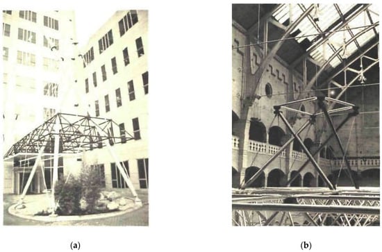
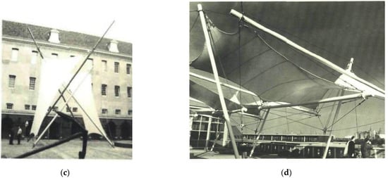
Figure 8.
Tensegrity structures by Eekhout (images taken from [43]): (a) Entrance canopy in Diemen. (b) Support of triangular truss bridge in Amsterdam. (c) Tensile structure in the Amsterdam Maritime Museum. (d) Hemweg canopy in Amsterdam.
At the same time that Fuller designed the Aspension dome, Kenneth Snelson tried to reflect the floating compression concept on a roof. He included it in his first patent by using the x-shaped units [23]. However, it was not until some years later that he accomplished his idea of building the first tensegrity grid by juxtaposing several simple modules (Figure 9a). René Motro and Ariel Hanaor continued this idea related to double layer tensegrity grids (DLTGs) [14,44]. When generating a single or double curvature from them, it is possible to generate a dome-like structure. This was partially achieved by Katherine Liapi [45]. They designed a “semi-open exhibition space” submitted as an entry to the international architectural competition “Ephemeral Structure for the City of Athens” (Figure 9b). The structure is a vaulted dome composed of interconnected detachable and deployable four square-based tensegrity units.
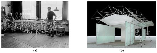
Figure 9.
(a) Kenneth Snelson working in his studio in 1961 with a DLTG (Illustration donated by the artist). (b) “Semi-Open Exhibit Space”: Entry for the international competition on the design of “Ephemeral Structure for the City of Patras” [45] (Image courtesy of Katherine Liapi).
Probably, these DLTGs are the most promising tensegrity configurations for architectural roofing. These are composed of tensegrity units that form double-layer cable nets held apart by a set of disconnected rigid members. DLTGs were used again by Liapi et al. [46] to build different types of roofs. The first example (Figure 10a) shows a patio roof for a bank annex in Greece, composed of 4T-Prisms (2007) and the second one (Figure 10b) shows an Information Pavilion for “Patras Cultural Capital of Europe” in Greece, made also by the juxtaposition of 4T-Prism or Simplex (2006).
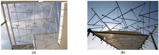
Figure 10.
Applications of Double-Layer Tensegrity Grids: (a) Patio roof in Greece; (b) Exhibition Pavilion in Patras (Greece), both by Katherine Liapi [46]. (Images courtesy of Katherine Liapi).
One of the main advantages of this type of structures is the foldability. In 2014, Gómez-Jáuregui et al., built a Deployable DLTG (DDLTG) composed of Quastruts [47] (Figure 11). When some of the continuous wires were released, it was possible to fold the whole structure (originally 16 m2) to a folded configuration with a perimeter less than 1.80 m, being contained in a cylinder of 0.28 m radius and 1.70 m height. The structure could be easily stored, transported and erected quickly and easily, allowing it to be used as a temporary shelter, exhibition roof structure, etc.
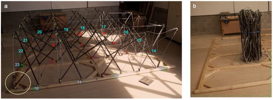
Figure 11.
DDLTG 4 × 4 m2 in its unfolded (a) and folded (b) configurations. Lower inner nodes are numbered in red and nodes of the lower boundary are numbered in cyan.
At Tokyo University, Kawaguchi et al. [48] built two tensegrity skeletons to support a membrane roof that covers the White Rhino (Figure 12). The tensegrity structures were built from the so-called ‘Simplex’ tensegrity, composed of three struts and nine strings. These units have one infinitesimal inextensional displacement mode, a twisting motion between the upper and lower triangles, in which the frame exhibits extremely low rigidity. Thus, there were added three more tendons between six unconnected points of Simplex in order to increase its structural rigidity drastically. Additionally, the frame was completed with a set of three suspension tendons supporting an isolated vertical strut that maintains the membrane roof and transmits its external loads to the tensegrity frame.
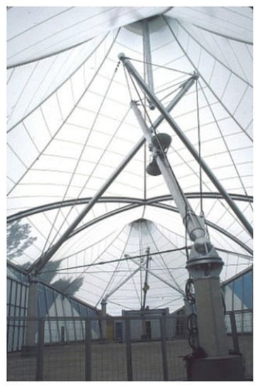
Figure 12.
Tensegrity skeleton White Rhino [48].
Recent studies on the matter conducted by Feng et al. [49] have proposed a wave-curved tensegrity dome which provides more options for architectural design. Another hybrid cable dome, among many others, was suggested by Asghari et al. [50], where they replaced the conventional concrete ring with a flexible tensegrity torus. Even though both proposals are just structural designs and have not been applied to real constructions yet, it is a signal that there are still some research groups pushing the boundaries of tensegrity applications for domes and roofs.
2.3. Bridges
One tensegrity bridge worth mentioning is the Kurilpa Bridge (Figure 13), designed by Arup, Cox Rayner and Baulderstone and built in 2009 in Brisbane [51]. This bridge is 470 m long and 6.5 m wide. It has two large platforms supported by a tensegrity structure, which is formed of 20 structural steel masts and 16 flying struts connected by a set of strings. This structure rests on two 8-metre reinforced concrete piers. Although the entire upper structure of the bridge was built following the tensegrity principles, its main platform is a continuous member. In addition, there are several points where the struts are joined to this horizontal deck.
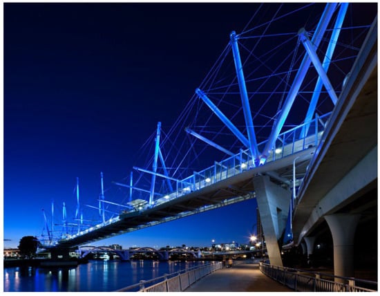
Figure 13.
Tensegrity-inspired design for Kurilpa bridge by Arup (Courtesy of Christopher Frederick Jones/CFJPhotography www.cfjphoto.com.au, (accessed on 15 September 2022)).
Some other prototypes for tensegrity-based footbridges have also been fabricated. One example is the pedestrian bridge designed by Rhode-Barbarigos et al. [52] (Figure 14a), composed of four identical tensegrity modules of 5 m in length, adapting a previous design by Motro et al. [53]. They developed the original concept through a parametric design study of three potential module configurations.
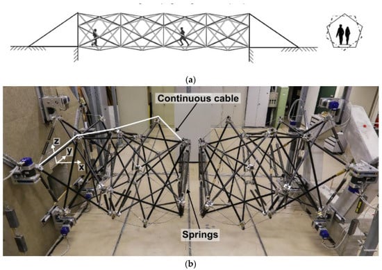
Figure 14.
(a) Pedestrian tensegrity bridge proposed by Rhode-Barbarigos et al. [52] (Image courtesy of L. Rhode-Barbarigos). (b) Evolution of the deployable tensegrity footbridge [54] (Image courtesy of N. Veuve).
The evolution of this deployable tensegrity footbridge was developed some years later at the École Polytechnique de l’Université de Lausanne by Veuve et al. [54,55]. This project studied the deployment of a clustered-cable-spring tensegrity configuration that was adapted from the previous design. The bridge in this case is composed of four identical pentagonal ring modules connected together in a hollow-rope system. Each pentagonal ring module had 15 struts and 30 cables. Figure 14b shows a 1/4 scale model that was designed, manufactured and assembled at their laboratory in Laussanne. The deployment of the structure could be achieved by varying the length of the active cables; through this process, the shape of the structure converts from a compact state to an expanded configuration.
2.4. Platforms
Construction and application of platforms have been based mainly on the use of the previously mentioned DLTGs.
Intending to solve a sea accessibility issue that arises people with reduced mobility, the idea of the tensegrity platforms emerged (Figure 15). Leaded by Averseng’s previous works, Hrazmi et al. [56] discussed the use of modular platforms consisting of variable and expandable configurations, formed by the juxtaposition of several elementary, rectangular and portable modules of limited size. The platform’s structure is a DLTG system inspired by the “Tensarch” project [57].
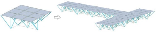
Figure 15.
Tensegrity platform proposed by Hrazmi et al. [56] (Image courtesy of J. Averseng).
One so-called tensegrity platform is the Blur Building [58]. This tensegrity-inspired building was constructed for the Swiss Expo 2002 in Yverdon-les-Bainst, Switzerland (Figure 16). As the architects describe it, this piece was meant to mimic the atmosphere. It is built from a system of horizontal frame, vertical struts and diagonal cables that cantilever out over the lake from piles in the water. Only the vertical struts are not connected to the main frame, so the principle of tensegrity is not fully achieved.
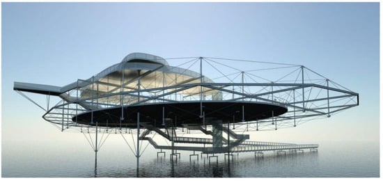
Figure 16.
The Blur Building by Diller and Scofidio (image taken from https://dsrny.com/project/blur-building, (accessed on 15 September 2022)) [58].
2.5. Drilling Machinery
A recent study conducted by Khaled et al. [59] explored the application of tensegrity structures for Earth and Space drilling operations. The drilling rig consists of two parts: the table and the tensegrity structure. The tensegrity structure is formed of 20 struts and 24 strings that build a tensegrity T-Bar and D-Bar units (Figure 17). Based on drilling tests, the authors determined that tensegrity structures proved to be a minimum mass structure solution for the fundamental loading conditions encountered while drilling. In addition, the structure can be easily disassembled. Since some of the struts are in contact, this example could be considered a pseudo-tensegrity system.
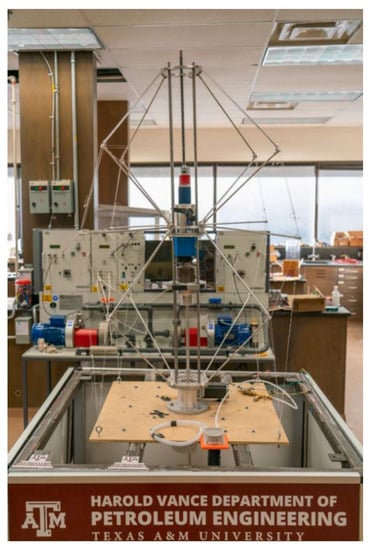
Figure 17.
Tensegrity drilling rig prototype [59].
2.6. Facades
Some studies on tensegrity building facades have been conducted during the last years. The first to mention is the work by Kabošová et al. [60]. In this paper, they aimed to obtain wind-adaptive skins for buildings; with this purpose in mind, they built a DLTG in which some of the tensile elements were replaced by fabrics (Figure 18a). The shape of the structure changes due to the wind pressure, to which the structure responds passively.
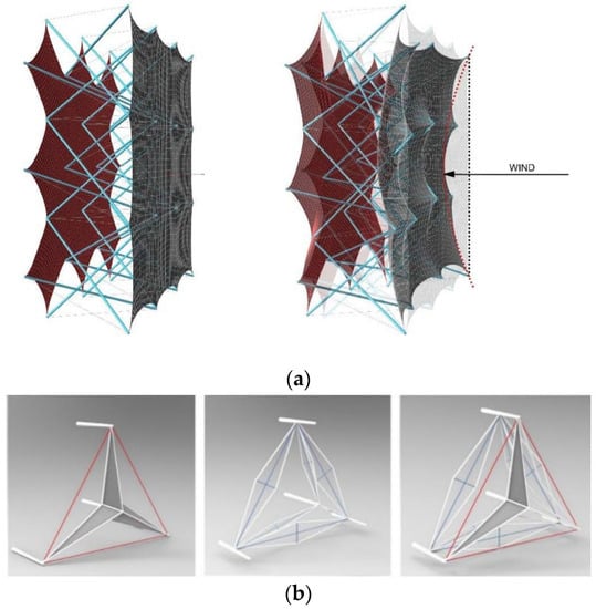
Figure 18.
(a) Wind-adaptive element. Reprinted/adapted with permission from Ref. [60]. (b) TABS module, D-bar element and WTABS system [61] (Image courtesy of Diana Peña).
Another similar application is the ‘Wind Tensegrity Al Bahar Screen’ (WTABS) [61]. This study provided comprehensive computational models in matrix and vector forms for the simulation of the dynamics of solar façades with a tensegrity-based origami architecture. The tensegrity module they used to build the screen was named TABS (Figure 18b). This module was expanded with a series of D-bars with strings wrapped with piezoelectric PVDF films to harness the mechanical energy.
3. Space Applications
In the following sub-sections, we will describe some space application proposed by Gunnar Tibert in his doctoral thesis [62]. There are some other authors that have proposed applications for tensegrities in the field of space explorations, but in his thesis, Tibert explains clearly how there are three main types of deployable structures needed in space: masts, antennas and solar panels. Masts are used for separating electronic instruments, for reducing interferences or for supporting other structures such as solar arrays. Antennas are used to communicate and observe the Earth and to perform astronomical studies. Finally, solar panels are used for converting light from the sun into electricity that can be used to power electrical loads in space.
3.1. Masts
As previously mentioned in the section Towers, Snelson described the construction of tensegrity structures by simple modules in his patent “Continuous tension, discontinuous compression structures” [23]. One of the structures he defined is a three-strut module mast. This mast is created by assembling triangular prisms (Simplex) on top of each other. Furuya [63] was a pioneer in studying foldable/deployable tensegrities, introducing the fundamental geometrical characteristics for deployment of tensegrity masts and some conceptual considerations for the one-dimensional deployable tensegrity.
Following Snelson’s configuration, Tibert [62] proposed the four-stage mast, which was the third tensegrity mast built at DSL (Deployable Structures Laboratory) (Figure 19a). With bi-stable struts, composed by four Simplex, it was the first one that could be folded in a satisfactory way.
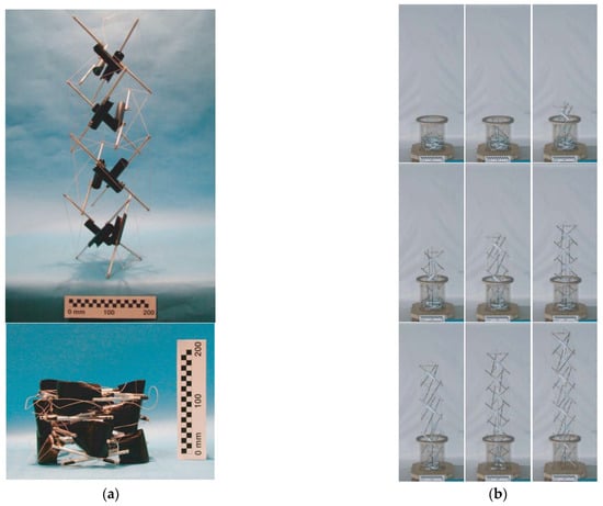
Figure 19.
Examples of deployable tensegrity masts: (a) Deployment of the four-stage mast [62]. (b) Deployment of the eight-stage mast [64]. (Images courtesy of Gunnar Tibert).
Tibert and Pellegrino [64] studied different masts that had been previously proposed, in order to find one suitable for deployment. They ended up deploying an eight-stage mast, as shown in Figure 19b. The major problem they found was that “the mast had no stiffness during deployment. It might be possible to provide full stiffness to the deployed part through a special canister, which would have the role of the struts and prestress the cables”.
The current state of the art is the primary deployable structure for the STRM (Shuttle Radar Topography Mission), consisting of the 60-metre-long ADAM (Able Deployable Articulated Mast). At the end of its length, the ADAM can support an antenna weighing 360 kg and can also carry electric and fiber-optic cables weighing a couple hundred kilograms, as well as a gas line. [62].
Very recently, some authors have tried to answer the question about which tensegrity column would be the best for the purpose of deployable tensegrity columns [65]. They focus the research on four tensegrity columns (in various deployment configurations), some of them are included in Figure 2. The methodology was based on computer simulations with the finite element analysis (FEA) and multibody dynamics (MBD) software to provide quantitative and qualitative results.
3.2. Antennas
One of the first contributions to the deployable aerospace structures was made by Knight in his thesis [66]. In this work, he proved that it is possible to build deployable structures using a kinematic platform geometry. The tensegrity prism used for this purpose was a 6-6 (hexagonal antiprism), and the approach to unfolding was to manipulate the legs connecting the hub to the antenna to create a tensegrity structure (Figure 20a). He proposed an improvement for the 6-6 design, resulting in the structure shown in Figure 20b. In 2001, Knight et al. patented the concept previously studied [67]. It describes a tensegrity antenna support architecture driven by screw movements. The deployment of the antenna should be performed by controlling the adjustable energy focus range.
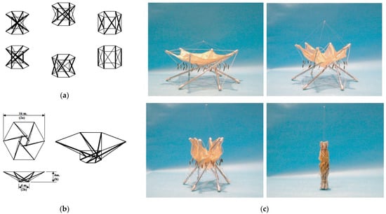
Figure 20.
(a) Creation of 6T-Prism Structure Rotation from a hexagonal prism [66]. (b) The original proposal for the deployable tensegrity antenna [66]. (c) Prototype for the deployment of the antenna [62] (Image courtesy of Gunnar Tibert).
The next idea of a tensegrity-based antenna was given by Tibert and Pellegrino [68]. In this paper, they developed a reflector for an antenna made of three parts: a deployable ring structure, two identical cable nets connected by tension ties, and the reflecting mesh, attached to the front net. They also demonstrated that the structure can be easily folded into a compact configuration. This design was used and improved by Tibert [62], resulting in a feasible antenna (Figure 20c) for a future small-satellite mission that approximately meets the requirements on the stowed dimensions and the mass goal.
In 2013, ESA promoted a project for large antenna reflectors, developed by Kayser Italia, University of Rome TorVergata and KTH (Stockholm, Sweden) [69]. They proposed a deployable tensegrity ring for a small satellite deployable structure (Figure 21). One of the main conclusions was the reliability of the prototype by means of a drastic reduction in the number of articulated joints in comparison with non-tensegrity architectures. It was finally the object of a patent granted in 2016 [70].
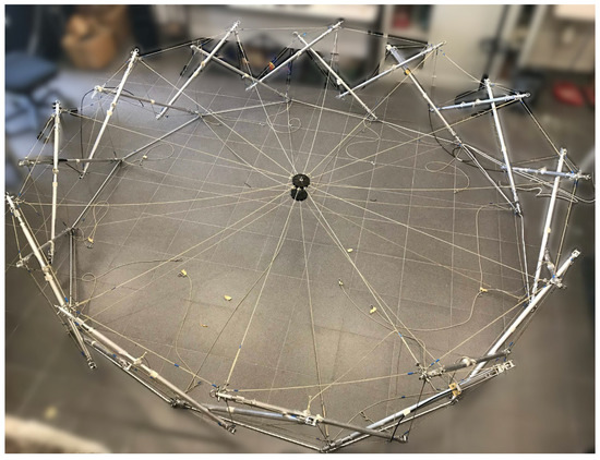
Figure 21.
Deployable tensegrity ring for a small satellite [69]. (Image courtesy of Andrea Micheletti).
3.3. Rovers
Another potential application of tensegrity structures is the fabrication of rovers for space exploration. One of the most paradigmatic examples is the Super Ball project [71]. However, there are many other examples that will be elaborated in the next section, focused on electromechanical engineering and robots. Most of those robots have locomotion properties that could be applied to rovers for space exploration.
4. Robots and Electromechanical Engineering
Tensegrity structures have been found in several biological systems. Ingber [72] demonstrated that tensegrity structures are similar to cytoskeleton structures of unicellular organisms, some of which are known to move. This discovery inspired the construction of soft robots which try to resemble biological systems (e.g., cells) [73].
Soft robots are more versatile than the rigid ones due to their ability to absorb forces and interact with unstructured environments. These features make them perfectly suitable for space exploration, especially when targeted at landing operations and interaction with unstructured and uncertain environments [20].
In [20], tensegrity robots were classified regarding their ways of motion into uniaxial movements, bidirectional movements, movements in 3, 4 and 6 degrees of freedom, crawling, walking, climbing, turning, hopping, jumping and even swimming. We will use this classification to frame the possible applications of tensegrity structures in the field of robotics.
4.1. Sensors
Tensegrity structures have shown intrinsic properties that were exploited in this study by Sultan and Skelton [74]. Even though it is a theoretical work, the authors explain how to construct smart sensors able to perform simultaneous measurements of six different quantities: three orthogonal forces and three orthogonal torques. The tensegrity structure shown in Figure 22 is a 6-strut and 18-string structure. It is the so-called tensegrity extended cuboctahedron, the shape of which resembles that of an icosahedron. It consists of eight regular triangles and twelve irregular isosceles triangles. The broken lines represent the upper and lower triangular bases.
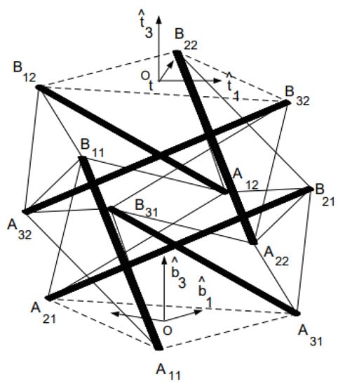
Figure 22.
Tensegrity structure of the sensor, with a triangular fixed base (A11A21A31) and a triangular rigid top (B12B22B32), conforming with the other vertices (AijBij) an expanded cuboctahedron. Reprinted with permission from Ref. [74].
In this configuration, certain cables serve as both structural elements and sensing elements that measure their own lengths. The measurements obtained from these cable sensors are then used as inputs to a dynamic state estimator which produces the assessments.
4.2. Crawling Robots
Tensegrity structures were applied to mobile robotics for the first time by Paul et al. [75,76]. They introduced the idea of legged robots based on a three-strut tensegrity robot (Figure 23a) and a four-strut tensegrity robot, both of which can crawl forward, by changing the position of the center of gravity, with an appropriate set of gait cycle.
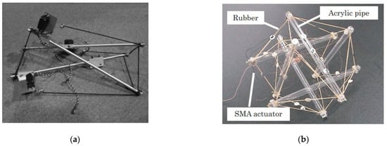
Figure 23.
(a) Crawling robot built by Paul [76]. (Image courtesy of Valero Cuevas) (b) Crawling robot proposed by Shibata [77].
Shibata et al. [77] proposed another example of a crawling robot. They designed a tensegrity structure with 6 struts and 24 strings (expanded cuboctahedron), resulting in a spherical robot (Figure 23b). The principle of crawling, in this case, was based on body deformation, which can be accomplished by the variation of the gravitational potential energy caused by deformation. In another project, proposed by Li et al. [78], for the same typology of robot, a control method based on the genetic algorithm for controlling the crawling of a TR-6 tensegrity robot was used.
4.3. Three-DoF (Degrees of Freedom)
Camps and Mirats-Tur Camps developed a three-strut prismatic tensegrity robot (Figure 24a) that was anchored to the ground [79]; they allowed its bars to change length, resulting in the possibility to control three DoF in the space. This study provided a first insight of the structure actuation and sensing for producing tensegrity robots’ movements.
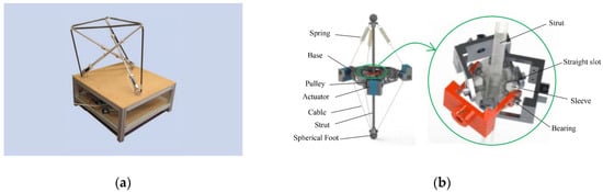
Figure 24.
(a) Robot proposed by Mirats-Tur [79]. (b) Tensegrity leg proposed by Cui [80].
Another recent example is proposed by Cui et al. [80] in a tensegrity leg (Figure 24b) by combining a tensegrity structure and a rigid mechanism to build a quadruped robot. This three-DoF tensegrity leg is uncoupled and fully actuated. The quadruped robot is built from four identical tensegrity leg modules. As they note, “the quadruped robot shows unique walking ability, high load performance and terrain adaptability”.
4.4. Uniaxial Robots
Böhm and Zimmerman [81] developed a vibration-driven locomotion with compliant tensegrity structures, using only a single actuator. Their tensegrity robot consisted of two equal angled struts indirectly interconnected through eight equal springs (Figure 25), inspired on the V-shape tensegrity module proposed by Raducanu and Motro in a patent [82]. A uniaxial bidirectional locomotion was achieved in symmetric tensegrity structures with a symmetric actuator.
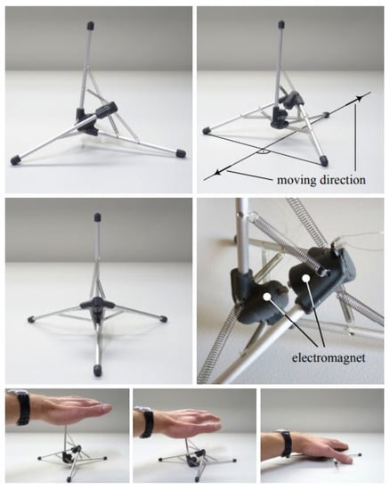
Figure 25.
Tensegrity robot proposed by Böhm and Zimmerman [81].
4.5. Rolling Robots
When it comes to rolling tensegrity robots, most of the examples will be about six-strut tensegrity robots (expanded cuboctahedrons), due to their spherical shape. One of the first rolling tensegrity robots was proposed by Koizumi et al. [83]. This robot was built of 6 rigid struts and 24 pneumatic McKibben actuators, working as tensional elements (Figure 26a). Their motion principle was once again based on the ability of tensegrity structures to reach stable states. They applied pressure using the actuators to shrink it, forcing the imbalance, which will force the structure to roll into another stable state.
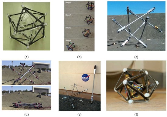
Figure 26.
(a) Prototype of 6-strut tensegrity robot proposed by Koizumi and Shibata [83]. (b) Rolling robot proposed by Wang [84] (Image courtesy of Shengqiang Cai). (c) Super Ball v1 [85]. (d) Super Ball v2 deployed. (e) NASA robots—left: ReCTeR, right: modular tensegrity platform. (Images courtesy of NASA) (f) Robot proposed by Khazanov (image courtesy of John Rieffel) [86].
Other rolling tensegrity robots based on the same motion were proposed by Wang et al. [84]; in this case, the actuation method used an artificial muscle fibre made up from a liquid crystal elastomer (LCE)–carbon nanotube (CNT) composite that can generate large and reversible light-actuated deformation, and thus enables light-powered motion of the tensegrity robot. The proposed robot for this task is shown in Figure 26b.
Probably one of the most iconic rolling tensegrity robots that we must mention is the Super Ball v2 [71,87]. This robot was the second version of a robot built for the NASA project together with Dynamic Tensegrity Robotics Lab (DTRL). This project intended to explore the concept of a “tensegrity rover which may self unpack from long term storage, survive the impact of landing on a planetary body, and locomote to science locations once on unknown terrain”. The first version [85] of the rover was a six-bar icosahedron (Figure 26c), which succeeded in showcasing a large-scale tensegrity robot built for locomotion. The objective of creating a second-generation prototype was to withstand impacts on a much larger scale, while also focusing on meeting other design priorities such as having a two-meter actuation stroke, reliable force sensing, low-friction, low wear cable routing, and the ability to actuate all 24 cables within the prototype. Additionally, the goal was to achieve a system mass of under 40 kg (Figure 26e). As mentioned before, the symmetrical spherical shape of the tensegrity icosahedron makes it advantageous for rolling movement. In addition, the tensegrity icosahedra can be folded into a flat star configuration, as shown in Figure 26d, which is interesting for future space exploration because of reduced mission payload expenses.
The actuation method proposed for the Super Ball v2 was a steerable locomotion controller; they validated their design by proving it capable of moving in specific trajectories and navigate around obstacles [88].
Several methods for controlling the direction in which the robot rolls were also proposed by different authors: analytic based on finite elements [89] or a path planning based on an A* modified algorithm [90].
Another way of rolling was proposed by Khazanov et al. [86]. They introduced a new way of motion in which they used a six-strut tensegrity structure where the tensile elements were springs. The robot was actuated by vibration motors (Figure 26f). They designed the structure to maximize its resonant possibilities, and they made it roll into different positions just by vibrating it at specific frequencies.
All these examples of tensegrity robots haven shown good response to movement in difficult terrains such as sand, pebbles or small rocks, which would make them suitable for space exploration in other planets or satellites.
4.6. Hopping and Rolling Robots
A tensegrity ball (TT-3), shown in Figure 27, was presented by Kyunam in his doctoral thesis [91], related to the Super Ball Project already mentioned previously. It combined hopping and rolling as a way of motion. Again, it is the same tensegrity structure with six bars. This robot’s goal was to move in lunar exploration. The propulsion method used was nitrogen cold gas thrusters. In addition, gimbals were suggested as a method of controlling orientation. They decided to use an A-Algorithm to search the possible paths. As they mention, the robot “presents a 10 kg tensegrity ball probe that can quickly and precisely deliver a 1 kg payload over a 1 km distance on the Moon”.
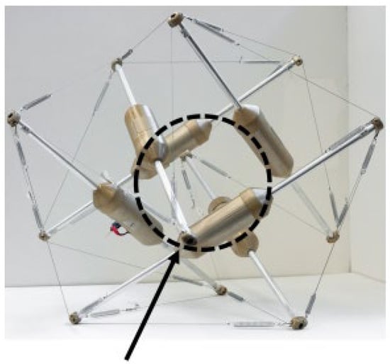
Figure 27.
Hopping and rolling robot proposed by Kyunam [91].
4.7. Jumping Robots
A two-dimensional tensegrity robot was proposed by Schorr et al. [92]. They used a two-dimensional tensegrity structure equipped with two actuators, intended to change the prestress state of the structure (Figure 28). This robot is able to jump over gaps or to overcome obstacles, which might be crucial when it comes to exploration in space. Due to its capability of changing the equilibrium configuration of the tensegrity structure in a suitable manner, strain energy is transformed into kinetic energy, which causes the complete locomotion system to take off. There is no need for extra actuators for the robot.
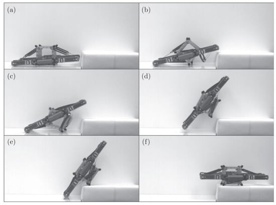
Figure 28.
The jumping mechanism during various states (a–f) of the jumping locomotion [92].
4.8. Climbing Robots
In 2017, Chen et al. [93] proposed the TT-4, a six-bar spherical tensegrity robot, shown in Figure 29a, to perform consistent uphill locomotion on steep inclines. They developed a novel multi-cable actuation scheme. They also implemented artificial intelligence to optimize locomotive gaits on different inclines and generate optimal tensegrity topologies.
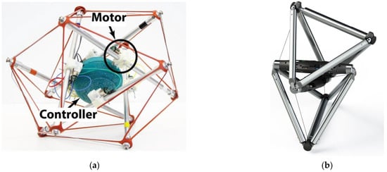
Figure 29.
(a) The TT-4 mini robot proposed by Chen [93] (b) Render of the DuCTTv2 Prototype [94] (image taken from https://jeffreyfriesen.me/projects/, (accessed on 15 September 2022)).
A great example of a climbing robot is the one created by Friesen et al. [94]. The DuCTTv2 (Duct Climbing Tetrahedral Tensegrity), being the first fully functional duct-climbing tensegrity robot. It does so with an average climb speed of 1.4 cm/s. This robot is built from two nested tetrahedral structures connected by eight actuated cables (Figure 29b). These tetrahedrons create an over-actuated system which enables six-degrees-of-freedom motion.
4.9. Environmental Adaptable Robots
Recently, a shape recognition method was proposed by Li et al. [95] employing three-strut tensegrity structures actuated by McKibben muscles and soft sensors (Figure 30a). They connected several tensegrity prisms forming a bigger system to be capable of recognising three-dimensional environments.
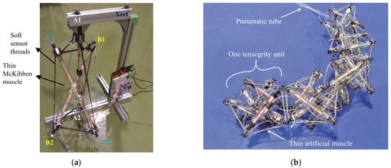
Figure 30.
(a) Tensegrity robot proposed in [95], where top vertices are labelled as A1, B1 and C1, while bottom vertices are labelled as A2, B2 and C2, while. (b) Soft artificial robot driven by thin artificial muscle [96]. (Images courtesy of Hiroyuki Nabae).
Later, Kobayashi et al. [96] developed a light soft tensegrity robot driven also by McKibben muscles. What they called the “4/3 muscle winding method” is a system that enables large deformation in a one-unit structure. Their tensegrity robot consists of several six-strut tensegrities, which they call units, connected to form an inchworm robot (Figure 30b). This robot was created with the purpose of eventually being able to move in unknown spaces by recognizing the shape of the space and the environment around it.
4.10. Wheels
Nearly at that same time, Crowthe et al. [97] designed, built and tested a series of TW (tensegrity-based wheels). They all follow the same general construction: a number of radial struts radiate out from the wheel axis, while transverse struts extend along the width of the wheel (Figure 31).
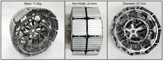
Figure 31.
Second iteration of the TW (tensegrity-based wheel) [97].
4.11. Underwater Robots
Shibata et al. [98] proposed a portable, lightweight underwater robot capable of translating and rotating, necessary for inspecting marine structures such as breakwaters, pipes and quay walls (Figure 32a). With this purpose, they designed a three-strut tensegrity structure connecting three pipes with rubber strings. They described a transformation mechanism for their underwater robot with a deformable tensegrity structure. Similar to this project, but more recent, Xu et al., proposed the U3DTT, an Underwater 3D Tactile Tensegrity, which structure is more complex, based on the expanded cuboctahedron [99]. It uses soft self-powered triboelectric nanogenerators and deep-learning-assisted data analytics, proving to have several degrees of freedom, a high sensitivity, quick response rates and shape adaptability, with the advantage of not being very expensive.
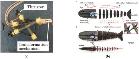
Figure 32.
(a) Prototype of the underwater robot proposed by Shibata [98]. (b) The bio-tensegrity fish robot by Shintake et al. [100]; top view: the robot in disassembled condition and bottom view: final assembly of the system.
Another bio-inspired (like those of next section), fish-like robot based on a tensegrity system was developed by Shintake et al. [100]. They built a prototype in the form of a rainbow trout powered by a water-resistant servomotor located in the robot’s head (Figure 32b). While the elastic cables of the tensegrity structure simulate the muscles, the rigid elements play the bone/tissue’s part. Their authors claim that the system is a class k = 2 tensegrity structure, significantly simpler than others used for underwater robots. When they tested the robot’s swimming speed, it reached 0.23 m/s, which is comparable to previous robots of this kind.
4.12. Bio-Inspired Robots
Tensegrity spines, as part as models of human anatomy (which will be exposed later), have been developed by Flemons [101] and Levin [102]. These spines have been referenced in later work in the robotics industry (Figure 33).
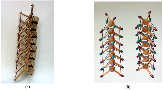
Figure 33.
(a) Levin’s tensegrity model of the spine [102]. (b) Model of a tetrahedral vertebral mast built by Flemons [101].
Levin is considered to be the originator of the biotensegrity concept [103], having published several papers on the matter. In 2011, Levin proposed a tensegrity-truss system to model the spine (Figure 33a), distributing the loads through the system only in tension or compression. His model was nondependent on gravity to hold it together and could stand static and dynamic forces.
Just a little later, Flemons stated that “each vertebral body in a spine bears a formal topological resemblance to a stellated tetrahedron. A sequence of these tetrahedrons suspended as a tensegrity mast can illustrate the equivalent spinal properties of load bearing combined with flexibility and rotation”. He developed several spine models [101] based on previously invented masts. One of his models is built from four strings composing a tensegrity saddle joint, and another four strings running along the outside (Figure 33b). All eight strings were being actuated.
Based on these works, the NASA Tensegrity Robotics Toolkit (NTRT) [104] developed a technique for the rapid design of tensegrity robots via simulation. They used multiple designs of tetra-spines to build their hardware prototype that employs 12 DC motors, 12 load cells and vectran cables (Figure 34a).
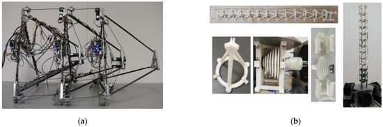
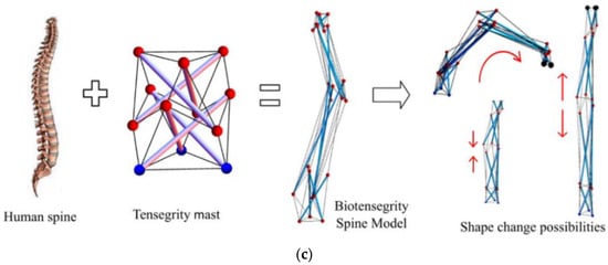
Figure 34.
(a) Hardware prototype of tetra-spine built by NASA [104]. (b) Spine robot prototype proposed by Feng [105]. (c) Biotensegrity diagram of the tensegrity spine model and the shape change possibilities [106].
In 2021, Feng et al. [105] proposed a tensegrity spine robot also inspired on the vertebrates’ spine. To replicate a soft spine structure, this robot is supported in a tension network and connected by springs (Figure 34b). In the paper, the authors mention how “this robot has the advantages of lightweight, compliance, and a high strength-to-weight ratio, which suggest good environmental adaptability and manipulation controllability”, properties that make it suitable for potential application prospects in space debri capturing.
Later, Lian et al. [106] presented a form-finding method for three different variations of k = 1 biotensegrity spine models (Figure 34c). They proposed an algorithm capable of simulating the shape change via four states. The algorithm can search for the optimal forced elongation of elements in tension and guarantee that they do not become slack after the configuration changes.
4.13. Unmanned Aerial Vehicles (UAVS)
Unmanned Aerial Vehicles (UAVs) are meant to operate in environments with obstacles hard to detect and difficult to avoid. A design to achieve a vehicle which is collision-resistant at high speed was proposed by Zha et al. [107], based on the expanded cuboctahedron. To achieve this collision resilience, they implemented an icosahedron tensegrity protection, as it is shown in Figure 35. The tensegrity structure is positioned so that it can benefit from its ability to distribute load among its parts while preventing them from suffering bending moment during collisions. As a result, the structure can provide high impact resilience with a light weight, which makes it a feasible option for planetary landers and exploratory rovers.
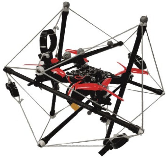
Figure 35.
The icosahedron-structured aerial vehicle [107] (Image courtesy of Mark Mueller).
5. Applications on Human Anatomy
We have already mentioned the influence of Levin and Flemons to the biotensegrity field. They both presented several models of tensegrity structures inspired by human anatomy. However, there are several other interesting applications that should be taken into consideration.
5.1. Hand
In an effort to address the issue of inadequate impact resistance in traditional robot hands, Li et al. [108] selected a tensegrity structure to design a soft robotic hand with multiple degrees of freedom. At the point when the tensegrity structure experiences impact, it changes shape and fluctuates slightly and then returns to its initial configuration. Due to this characteristic, a finger can flex at arbitrary angles that are not achievable for human hands or standard robotic hands. The actuators that mimic synthetic muscles are constructed from McKibben. They proposed a tensegrity topology consisting of combining different tensegrity structures (Figure 36). They use a unit of tensegrity structure and its catenary structure connecting to a T-prism.
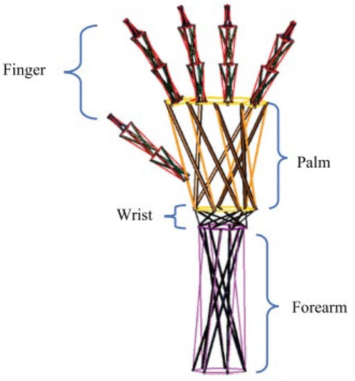
Figure 36.
Design of the tensegrity hand [108]. (Image courtesy of Hiroyuki Nabae).
5.2. Wrist
A tensegrity structure-based virtual rolling-contact joint with one DoF was proposed by Lee et al. [109] to manufacture a prosthetic wrist. They were capable of creating a prosthetic wrist based on tensegrity principles that meet the requirements of lightweight and wide range of motion. Its structure tries to mimic the ligamentous structure composed along with different anatomic parts as ligaments and bones.
A rolling-contact joint consists of two adjacent elements that roll against each other without slipping. The structure is compliant due to the strings’ innate elasticity. The mechanism the authors proposed is based on the tensegrity concept and follows kinematically the rolling-contact joint.
The wrist mechanism consists of three stiff bodies that replicate three rows of the human wrist, and twelve strings. The mechanism will be actuated with a tendon drive [109].
5.3. Cranial Vault
Scarr developed a cranial vault model maintained through tensegrity mechanisms rather than relying on a growing brain expansive force. His tensegrity model depicted compressive struts as cranial bones in the form of curve plates and dura mater (membrane located beneath and attached to cranial bones) as elastic tension cords [110]. The cranial bones are kept apart one from another by sutural ligament forming a ‘discontinuous compression’, as shown in Figure 37a.
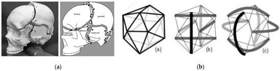
Figure 37.
(a) Tensegrity skull model [110] (b) Diagram showing how a geodesic tensegrity icosahedron: a, irregular icosahedron; b, expanded cuboctahedron and c, expanded cuboctahedron with curved struts (Images courtesy of Graham Scarr).
Cranial vaults, as Scarr described them, are “sphere-like tensegrity icosahedrons” that utilize close-packed minimal surface area with the aim of creating wider space to malleably house multiple functions (such as brain growth and intercellular signalling), preserving energy in an effective way.
However, this could be another example of false tensegrity; the reason behind this is that in a self-stable pure tensegrity structure, the elements in compression work under forces only in its main direction, whereas in this model, the elements under compression are curved; therefore, the forces are in different directions, creating bending moments.
6. Conclusions
The present work has intended to fill the lack of compilations and reviews about applications of tensegrity structures. Therefore, the authors have given an overview of all their actual applications, at the same time exposing their potential in all the fields they have contributed to (AEC, robotics, space, etc.) With this paper, we have explained the impact that tensegrity structures have been making in the different fields explored in the little time since their first official appearance in the late 1940s. In fact, we have found proof from 1921 that states that they are in fact more than 100 years old.
Additionally, thanks to the analysis of many publications for this review, we have concluded, to the best of our knowledge, that Kenneth Snelson had already designed a prototype for a cable dome or wire wheel dome in 1949, before the works by Geiger in the 1980s and Levy in the 1990s.
Several artists, architects and engineers have been captivated by their special properties and managed to give them a lot of different, creative and useful applications. Many of these studies are still open to further investigation, which will probably lead to more applications in the future.
We have also explained which are the main advantages of these kinds of structures (deployability, lightness, low control cost, etc.) and also their main disadvantages (high deflections, fabrication complexity, difficulty in form-finding and prestressed states, etc.) The former have helped to find some of the applications identified in this review and some others, but the latter are still a barrier to obtaining suitable solutions to real problems in architecture and engineering.
To conclude this review, we present all the data previously exposed in an easy and eye-catching way with some graphics shown below.
Taking a look at Figure 38, we can extract the following conclusions. First of all, the number of applications of tensegrity to these areas of knowledge have grown significantly from 2000 until now. Due to this fact, we are encouraged to believe that it will keep becoming more and more important in the future. In some cases, especially in architectural constructions for towers, domes and roofs, where the last examples of erected projects are not very recent, it may seem as though there is no active research on this topic. However, as can be seen in this histogram, interest is increasing continuously. The point is that there are many construction projects that have not been brought to reality yet due to the difficulty of building them at big scales.
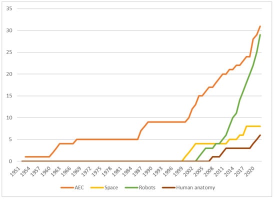
Figure 38.
Histogram showing the accumulated number of publications on tensegrity applications through the years on these four areas of knowledge.
Another direct conclusion is the fact that, although architectural applications have been the first to appear, tensegrity structures are still finding solutions to problems in the architectural field these days. Robotics is a field that has been gaining more importance in the last years, probably becoming the leader application for tensegrity structures by now. In the last 20 years, the number of publications about tensegrity robots is the same as those about AEC applications since mid-20th century. In addition, biotensegrity has led to the application of these structures in human anatomy, the last field in which tensegrity has been introduced.
Another indicator of the evolution of the interest on applications for tensegrity structures can be reflected in the number of patents published in the world. The Espacenet database maintained by the European Patent Office gives us the possibility of analyzing this progress. Figure 39 shows the histogram of the accumulated number of published patent applications with the term “tensegrity” in their title. It is evident that the number has increased exponentially during the last decade, which proves that this topic is gaining more and more attention among academics, industry and society.
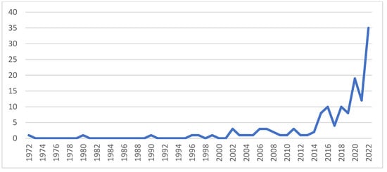
Figure 39.
Histogram showing the accumulated number of published patent applications with the term “tensegrity” in their title.
These numbers and this indicator must be considered cautiously, because there are many patents that are never built and, in fact, they can even be just ideas or concepts with barely any feasibility. Moreover, this histogram does not show only the patents that had been officially granted, but also all the patent applications published by WIPO or EPO [111].
Figure 40 shows the world map with all the countries in graded color that are participating to build the history of applications to tensegrity structures and have been mentioned in the current review paper.
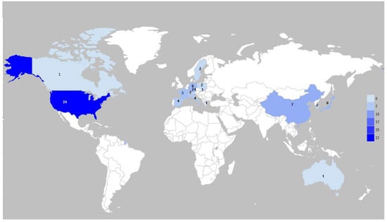
Figure 40.
World map showing the number of authors per country in the tensegrity field (values displayed in the legend on the right).
As we declared in the introduction, tensegrity was born in the United States and probably that is the main reason why this is, by far, the country that has participated the most in proposing tensegrity applications. Asia and Europe have also contributed a lot to this growth: on the one hand, China and Japan have been the leaders when it comes to tensegrity robots, especially in the last two decades; on the other hand, some European countries have been very much involved, for example, Spain, Germany, Italy and France.
The future of tensegrity structures is very promising, but there is still much more work to solve the difficulties and disadvantages exposed in the literature.
Author Contributions
Conceptualization, V.G.-J. and A.C.-R.; methodology, V.G.-J.; investigation, A.C.-R.; data curation, A.C.-R.; writing—original draft preparation, V.G.-J. and A.C.-R.; writing—review and editing, V.G.-J., C.M., P.L.-G. and A.C.-R. All authors have read and agreed to the published version of the manuscript.
Funding
This research received no external funding.
Data Availability Statement
No new data were created or analyzed in this study. Data sharing is not applicable to this article.
Acknowledgments
The authors would like to thank and acknowledge Julie McNamara for proof-reading the manuscript and improving the written quality of the text.
Conflicts of Interest
The authors declare no conflict of interest.
References
- Emmerich, D.G. Structures Tendues et Autotendantes; Ecole d’Architecture de Paris la Villette: Paris, France, 1988. [Google Scholar]
- Monoskop. Karl Ioganson. Available online: https://monoskop.org/Karl_Ioganson (accessed on 15 September 2022).
- Wikipedia. Karlis Johansons. Available online: https://en.wikipedia.org/wiki/Karlis_Johansons (accessed on 15 September 2022).
- Manríquez-Padilla, C.G.; Zavala-Pérez, O.A.; Pérez-Soto, G.I.; Rodríguez-Reséndiz, J.; Camarillo-Gómez, K.A. Form-Finding Analysis of a Class 2 Tensegrity Robot. Appl. Sci. 2019, 9, 2948. [Google Scholar] [CrossRef]
- Motro, R. Tensegrity: Structural Systems for the Future; Kogan Page Science: London, UK, 2003. [Google Scholar]
- Fuller, R.B. Everything I Know; Audiovisual interview. 1975. Available online: https://www.bfi.org/about-fuller/everything-i-know/ (accessed on 26 April 2023).
- Fuller, R. Tensile-Integrity Structures. U.S. Patent 3,063,521, 31 August 1959. [Google Scholar]
- Montuori, R.; Skelton, R.E. Globally stable tensegrity compressive structures for arbitrary complexity. Compos. Struct. 2017, 179, 682–694. [Google Scholar] [CrossRef]
- Skelton, R.E.; de Oliveira, M.C. Tensegrity Systems; Springer: Dordrecht, The Netherlands; Berlin/Heidelberg, Germany; London, UK; New York, NY, USA, 2009. [Google Scholar]
- Skelton, R.E.; Adhikari, R.; Pinaud, J.-P.; Chan, W. An Introduction to the Mechanics of Tensegrity Structures. In Proceedings of the 40th IEEE Conference on Decision and Control, Orlando, FL, USA, 4–7 December 2001. [Google Scholar] [CrossRef]
- Skelton, R.E.; Helton, W.J.; Adhikari, R.; Pinaud, J.-P.; Chan, W. An introduction to the mechanics of tensegrity structures. In The Mechanical Systems Design Handbook; CRC Press: Boca Raton, FL, USA, 2017; pp. 316–388. [Google Scholar]
- Gomez-Jauregui, V. Tensegrity Structures and Their Application to Architecture; Editorial Universidad de Cantabria: Santander, Spain, 2010. [Google Scholar]
- Gomez-Jauregui, V. Controversial Origins of Tensegrity. In Proceedings of the International Association for Shell and Spatial Structures (IASS) Symposium 2009, Valencia, Spain, 28 September–2 October 2009; pp. 1642–1652. [Google Scholar]
- Hanaor, A. Preliminary Investigation of Double-Layer Tensegrities; Civil-Comp Press: Edinburgh, UK, 1987; pp. 35–42. [Google Scholar] [CrossRef]
- Schodek, D.L. Structure in Sculpture; MIT Press: Cambridge, MA, USA, 1993. [Google Scholar]
- Song, K.; Scarpa, F.; Schenk, M. Form-finding of tessellated tensegrity structures. Eng. Struct. 2022, 252, 113627. [Google Scholar] [CrossRef]
- Sherbakov, S.S.; Basaran, C. On the development of tribo-fatigue as the new section of mechanics. Int. J. Mater. Struct. Integr. 2022, 14, 142–163. [Google Scholar] [CrossRef]
- Hernàndez-Juan, S.; Mirats-Tur, J.M. Tensegrity frameworks: Static analysis review. Mech. Mach. Theory 2008, 43, 859–881. [Google Scholar] [CrossRef]
- Mirats-Tur, J.M.; Hernàndez-Juan, S. Tensegrity frameworks: Dynamic analysis review and open problems. Mech. Mach. Theory 2009, 44, 1–18. [Google Scholar] [CrossRef]
- Liu, Y.; Bi, Q.; Yue, X.; Wu, J.; Yang, B.; Li, Y. A review on tensegrity structures-based robots. Mech. Mach. Theory 2021, 168, 104571. [Google Scholar] [CrossRef]
- Hernández-Montes, E.; Fernández-Ruiz, M.A.; Gil-Martín, L.M.; Merino, L.; Jara, P. Full and folded forms: A compact review of the formulation of tensegrity structures. Math. Mech. Solids 2018, 23, 944–949. [Google Scholar] [CrossRef]
- Sultan, C. Tensegrity: 60 Years of Art, Science, and Engineering. In Advances in Applied Mechanics; Elsevier: Amsterdam, The Netherlands, 2009; Volume 43, pp. 69–145. [Google Scholar] [CrossRef]
- Snelson, K. Continuous Tension, Discontinuous Compression Structures. U.S. Patent 3,169,611A, 16 February 1965. [Google Scholar]
- Emmerich, M.D.G. Structures Linéaires Autotendantes. FR 1,377,291, 6 November 1964. [Google Scholar]
- Schlaich, M. The Messeturm in Rostock—A Tensegrity Tower. J. Int. Assoc. Shell Spat. Struct. 2004, 45, 93–98. [Google Scholar]
- Snelson, K. Kennethsnelson. Available online: http://kennethsnelson.net/sculptures/towers/zig-zag-tower/ (accessed on 29 January 2023).
- Heartney, E. Kenneth Snelson: Forces Made Visible; Hudson Hills: Lenox, NY, USA, 2009. [Google Scholar]
- Pferfer, S.; Fuller, R.B.; Noguchi, I. Fuller and Noguchi: Story of a Friendship. 2011. Available online: http://www.domusweb.it/en/interviews/2011/09/01/fuller-and-noguchi-story-of-a-friendship.html (accessed on 11 November 2022).
- Fraddosio, A.; Marzano, S.; Pavone, G.; Piccioni, M.D. Morphology and self-stress design of V-Expander tensegrity cells. Compos. Part B 2016, 115, 102–116. [Google Scholar] [CrossRef]
- Marks, R.W. The Dymaxion World of Buckminster Fuller; Reinhold Publishing Corporation: New York, NY, USA, 1960. [Google Scholar]
- Fuller, R.B. Suspension Building. U.S. Patent 3,139,957A, 7 July 1964. [Google Scholar]
- Micheletti, A.; Podio-Guidugli, P. Seventy years of tensegrities (and counting). Arch. Appl. Mech. 2022, 92, 2525–2548. [Google Scholar] [CrossRef]
- Mollaert, M.M. Seoul Olympic Gymnastics Hall and Fencing Hall. Available online: https://www.tensinet.com/index.php/component/tensinet/?view=reference&id=3758 (accessed on 16 September 2022).
- Levy, M.; Jing, T.-F.; Brzozowski, A.; Freeman, G. Estadio Ciudad de La Plata (La Plata Stadium), Argentina. Struct. Eng. Int. 2013, 23, 303–310. [Google Scholar] [CrossRef]
- Oribasi, A.; Paronesso, A.; Dauner, H.-G. The new World Cycling Center in Aigle, Switzerland (Die neue Weltradsporthalle in Aigle, Schweiz). Stahlbau 2002, 71, 584–591. [Google Scholar] [CrossRef]
- Kiewitt, G. The new look of lamella roofs. In Architectural Engineering: New Structures; Fischer, R.E., Ed.; Mc-Graw-Hill/Architectural Record: New York, NY, USA, 1964; pp. 20–25. [Google Scholar]
- Geiger, D.H. Roof Structure. DE 3,579,034D1, 13 September 1990. [Google Scholar]
- Bin-Bing, W. Tensegrity structures as ‘ring beams’. J. Int. Assoc. Shell Spat. Struct. 1996, 37, 31–38. [Google Scholar]
- Peña, D.M.; Llorens, I.; Sastre, R.; Crespo, D.; Martínez, J. Application of Tensegrity to Tensile-Textile Constructions—Formfinding and Structural Analysis. J. Int. Assoc. Shell Spat. Struct. 2011, 2011, 67–81. Available online: http://hdl.handle.net/2117/19912 (accessed on 23 July 2022).
- Peña Villamil, D.M. Aplicación de los Principios del Tensegrity a las Construcciones Textiles Atirantadas. Ph.D. Thesis, Universidad Politécnica de Cataluña, Barcelona, Spain, 2012. [Google Scholar]
- Gupta, S.S.; Tan, Y.Y.; Chia, Z.P.; Pambudi, C.P.; Quek, H.; Yogiaman, C.; Tracy, K.J. Prototyping knit tensegrity shells: A design-to-fabrication workflow. SN Appl. Sci. 2020, 2, 1062. [Google Scholar] [CrossRef]
- Mortera Aguilar, A. Arquitectura Tensegrity con Bambú. Available online: https://worldbamboo.net/3cmb2016/Mart%C3%ADn%20Mortera.pdf (accessed on 21 January 2023).
- Eekhout, M. Architecture in Space Structures; Uitgeverij 010 Publishers: Rotterdam, The Netherlands, 1989. [Google Scholar]
- Motro, R. Tensegrity Systems for Double-Layer Space Structures. In Non-Conventional Structures, Proceedings of the International Conference on the Design and Construction of Non-Conventional, 8–10 December 1987, London, UK; Civil-Comp Ltd.: Edinburgh, UK, 1987; pp. 43–51. [Google Scholar]
- Liapi, K.A.; Kim, J. A Parametric Approach to the Design of Vaulted Tensegrity Networks. Int. J. Archit. Comput. 2004, 2, 245–262. [Google Scholar] [CrossRef]
- Liapi, K.; Jinman, K. Tensegrity Structures of Helical Shape: A Parametric Approach. In Proceedings of the 27th eCAADe Conference, Istanbul, Turkey, 16–19 September 2009; pp. 53–58. [Google Scholar] [CrossRef]
- Gomez-Jauregui, V.; Quilligan, M.; Manchado, C.; Otero, C. Design, Fabrication and Construction of a Deployable Double-Layer Tensegrity Grid. Struct. Eng. Int. 2018, 28, 13–20. [Google Scholar] [CrossRef]
- Kawaguchi, K.; Ohya, S.; Vormus, S. Long-Term Monitoring of White Rhino, Building with Tensegrity Skeletons; Institute of Industrial Science, The University of Tokyo: Tokyo, Japan, 2001. [Google Scholar]
- Feng, Y.; Yuan, X.; Samy, A. Analysis of new wave-curved tensegrity dome. Eng. Struct. 2022, 250, 113408. [Google Scholar] [CrossRef]
- Asghari, R.; Abedi, K.; Chenaghlou, M.R.; Shekastehband, B. Retrofitting of hybrid cable domes against strut buckling using di-pyramid (DP) module and force-limiting devices (FLD). Thin-Walled Struct. 2022, 180, 109737. [Google Scholar] [CrossRef]
- Ogunsote, O.O.; Arum, C.; Prucnal-Ogunsote, B. Aesthetic and Economic Imperatives in the Design of the Kurilpa Pedestrian Bridge as a Functional Tensegrity Structure. Infrastruct. Econ. Dev. Built Environ. 2018, pp. 249–260. Available online: https://www.proquest.com/wire-feeds/level-1-visual-inspection-kurilpa-bridge/docview/2038434379/se-2 (accessed on 5 July 2022).
- Rhode-Barbarigos, L.; Bel Hadj Ali, N.; Motro, R.; Smith, I.F.C. Designing tensegrity modules for pedestrian bridges. Eng. Struct. 2010, 32, 1158–1167. [Google Scholar] [CrossRef]
- Motro, R.; Maurin, B.; Silvestri, C. Tensegrity rings and the hollow rope. In Proceedings of the IASS International Symposium, Beijing, China, 16–19 October 2006; pp. 470–471. [Google Scholar]
- Veuve, N.; Dalil Safaei, S.; Smith, I.F.C. Deployment of a Tensegrity Footbridge. J. Struct. Eng. 2015, 141, 04015021. [Google Scholar] [CrossRef]
- Veuve, N.; Sychterz, A.C.; Smith, I.F.C. Adaptive control of a deployable tensegrity structure. Eng. Struct. 2017, 152, 14–23. [Google Scholar] [CrossRef]
- Hrazmi, I.; Averseng, J.; Quirant, J.; Jamin, F. Deployable double layer tensegrity grid platforms for sea accessibility. Eng. Struct. 2021, 231, 111706. [Google Scholar] [CrossRef]
- Motro, R. Tensarch: A tensegrity double layer grid prototype. Space Struct. 5 2002, 1, 57–66. [Google Scholar] [CrossRef]
- Gilewski, W.; Klosowska, J.; Obara, P. Verification of Tensegrity Properties of Kono Structure and Blur Building. Procedia Eng. 2016, 153, 173–179. [Google Scholar] [CrossRef]
- Khaled, M.S.; Chen, M.; Losoya, E.Z.; Rodriguez, L.A.; Guildin, E.; Skelton, R.E. Tensegrity laboratory drilling rig for earth and space drilling, mining, and exploration. Int. J. Solids Struct. 2022, 252, 111785. [Google Scholar] [CrossRef]
- Kabošová, L.; Kormaníková, E.; Kmet, S.; Katunský, D. Shape-changing tensegrity-membrane building skin. In Proceedings of the 4th International Scientific Conference Structural and Physical Aspects of Construction Engineering (SPACE 2019), Strbske Pleso, Slovakia, 13–15 November 2019. [Google Scholar] [CrossRef]
- Miranda, R.; Babilio, E.; Peña, D.; Santos, F.; Fraternali, F. Mechanics of Energy Harvesters Based on Tensegrity Solar Facades. In IOP Conf. Series: Materials Science and Engineering; IOP Publishing: Bristol, UK, 2020. [Google Scholar] [CrossRef]
- Tibert, G. Deployable Tensegrity Structures for Space Applications. Ph.D. Thesis, Royal Institute of Technology, Stockholm, Sweden, 2002. [Google Scholar]
- Furuya, H. Concept of Deployable Tensegrity Structures in Space Application. Int. J. Space Struct. 1992, 7, 143–151. [Google Scholar] [CrossRef]
- Tibert, G.; Pellegrino, S. Deployable Tensegrity Masts. In Proceedings of the 44th AIAA/ASME/ASCE/AHS/ASC Structures, Structural Dynamics, and Materials Conference, Norfolk, VA, USA, 7–10 April 2003. [Google Scholar]
- Zawadzki, A.; Sabouni-Zawadzka, A.A. In Search of Lightweight Deployable Tensegrity Columns. Appl. Sci. 2020, 10, 8676. [Google Scholar] [CrossRef]
- Knight, B.F. Deployable Antenna Kinematics Using Tensegrity Structure Design. Ph.D. Thesis, University of Florida, Gainesville, FL, USA, 2000. [Google Scholar]
- Knight, B.; Duffy, J.; Crane, C.; Rooney, J. Deployable Antenna. U.S. Patent WO2001076011A2, 11 October 2001. [Google Scholar]
- Tibert, G.; Pellegrino, S. Deployable Tensegrity Reflectors for Small Satellites. J. Spacecr. Rocket. 2002, 39, 702–709. [Google Scholar] [CrossRef]
- Ganga, P.L.; Micheletti, A.; Podio-Guidugli, P.; Scolamiero, L.; Tibert, G.; Zolesi, V. Tensegrity Rings for Deployable Space Antennas: Concept, Design, Analysis, and Prototype Testing. In Variational Analysis and Aerospace Engineering. Springer Optimization and Its Applications; Frediani, A., Mohammadi, B., Pironneau, O., Cipolla, V., Eds.; Springer: Cham, Switzerland, 2016; p. 116. [Google Scholar] [CrossRef]
- Scolamiero, L.G.; Zolesi, V.; Ganga, P.L.; Podio-Guidugli, P.; Tibert, G.; Micheletti, A. A Deployable Tensegrity Structure, Especially for Space Applications. EP 2,828,928A1, 18 May 2016. [Google Scholar]
- Vespignani, M.; Friesen, J.M.; SunSpiral, V.; Bruce, J. Design of SUPERball v2, a Compliant Tensegrity Robot for Absorbing Large Impacts. In Proceedings of the 2018 IEEE/RSJ International Conference on Intelligent Robots and Systems (IROS), Madrid, Spain, 1–5 October 2018; pp. 2865–2871. [Google Scholar] [CrossRef]
- Ingber, D.E. Cellular tensegrity: Defining new rules of biological design that govern the cytoskeleton. J. Cell Sci. 1993, 104, 613–627. [Google Scholar] [CrossRef] [PubMed]
- Ingber, D.E. Tensegrity-based mechanosensing from macro to micro. Prog. Biophys. Mol. Biol. 2008, 97, 163–179. [Google Scholar] [CrossRef]
- Sultan, C.; Skelton, R. A force and torque tensegrity sensor. Sens. Actuators A. Phys. 2004, 112, 220–231. [Google Scholar] [CrossRef]
- Paul, C.; Roberts, J.W.; Lipson, H.; Valero Cuevas, F.J. Gait production in a tensegrity based robot. In Proceedings of the 12th International Conference on Advanced Robotics (ICAR ’05), Seattle, WA, USA, 18–20 July 2005; pp. 216–222. [Google Scholar] [CrossRef]
- Paul, C.; Valero Cuevas, F.J.; Lipson, H. Design and Control of Tensegrity Robots for Locomotion. IEEE Trans. Robot. 2006, 22, 944–957. [Google Scholar] [CrossRef]
- Shibata, M.; Saijyo, F.; Hirai, S. Crawling by Body Deformation of Tensegrity Structure Robots. In Proceedings of the 2009 IEEE International Conference on Robotics and Automation, Kobe, Japan, 12–17 May 2009. [Google Scholar] [CrossRef]
- Li, B.; Wenjuan, D.; Wenjuan, L. Dynamic Modeling and Controlling for the Crawling. In Proceedings of the 2017 IEEE 7th Annual International Conference on CYBER Technology in Automation, Control, and Intel-ligent Systems (CYBER), Honolulu, HI, USA, 31 July–4 August 2017. [Google Scholar] [CrossRef]
- Mirats-Tur, J.M.; Camps, J. A Three-DoF Actuated Robot. IEEE Robot. Autom. Mag. 2011, 18, 96–103. [Google Scholar] [CrossRef]
- Cui, J.; Wang, P.; Sun, T.; Ma, S.; Liu, S.; Kang, R.; Guo, F. Design and experiments of a novel quadruped robot with. Mech. Mach. Theory 2022, 171, 104781. [Google Scholar] [CrossRef]
- Böhm, V.; Zimmermann, K. Vibration-driven mobile robots based on single actuated tensegrity structures. In Proceedings of the 2013 IEEE International Conference on Robotics and Automation, Karlsruhe, Germany, 6–10 May 2013. [Google Scholar] [CrossRef]
- Raducanu, M. Stable Self-Balancing System for Building Component. FR WO02081832A1, 9 April 2001. [Google Scholar]
- Koizumi, Y.; Mizuho, S.; Hirai, S. Rolling Tensegrity Driven by Pneumatic Soft Actuators. In Proceedings of the 2012 IEEE International Conference on Robotics and Automation, Saint Paul, MN, USA, 14–18 May 2012. [Google Scholar] [CrossRef]
- Wang, Z.; Li, K.; He, Q.; Cai, S. A Light-Powered Ultralight Tensegrity Robot with High Deformability and Load Capacity. Adv. Mater. 2019, 31, 1806849. [Google Scholar] [CrossRef] [PubMed]
- Sabelhaus, A.P.; Bruce, J.; Caluwaerts, K.; Manovi, P.; Firoozi, R.F.; Dobi, S.; Agogino, A.M.; SunSpiral, V. System Design and Locomotion of SUPERball, an Untethered Tensegrity Robot. In Proceedings of the 2015 IEEE International Conference on Robotics and Automation (ICRA), Seattle, WA, USA, 26–30 July 2015; pp. 2867–2873. [Google Scholar] [CrossRef]
- Khazanov, M.; Humphreys, B.; Keat, W.; Rieffel, J. Exploiting Dynamical Complexity in a Physical Tensegrity Robot to Achieve Locomotion. In Proceedings of the ECAL 2013: The 12th European Conference on Artificial Life, Taormina, Italy, 2–6 September 2013. [Google Scholar] [CrossRef]
- Bruce, J.; Caluwaerts, K.; Iscen, A.; Sabelhaus, A.P.; SunSpiral, V. Design and Evolution of a Modular Tensegrity Robot Platform. In Proceedings of the 2014 IEEE International Conference on Robotics & Automation (ICRA), Hong Kong, China, 31 May–7 June 2014; pp. 3483–3489. [Google Scholar] [CrossRef]
- Vespignani, M.; Ercolani, C.; Friesen, J.M.; Bruce, J. Steerable Locomotion Controller for Six-struts Icosahedral Tensegrity Robots. In Proceedings of the 2018 IEEE/RSJ International Conference on Intelligent Robots and Systems (IROS), Madrid, Spain, 1–5 October 2018. [Google Scholar] [CrossRef]
- Du, W.; Ma, S.; Wang, M.; Hirai, S. Force Analytic Method for Rolling Gaits of Tensegrity Robots. IEEE/ASME Trans. Mechatron. 2016, 21, 2249–2259. [Google Scholar] [CrossRef]
- Chang, J.; Li, B.; Liu, W.; Du, W. The Path Planning Method of Tensegrity Robot. In Proceedings of the 2018 IEEE 8th Annual International Conference, Tianjun, China, 19–23 July 2018. [Google Scholar]
- Kim, K.; Chen, L.-H.; Cera, B.; Daly, M.; Zhu, E.; Despois, J.; Agogino, A.K.; SunSpiral, V.; Agogino, A.M. Hopping and Rolling Locomotion with Spherical Tensegrity Robots. In Proceedings of the 2016 IEEE/RSJ International Conference on Intelligent Robots and Systems (IROS), Daejeon, Republic of Korea, 9–14 October 2016. [Google Scholar] [CrossRef]
- Schorr, P.; Zentner, L.; Zimmermann, K.; Böhm, V. Jumping locomotion system based on a multistable tensegrity structure. Mech. Syst. Signal Process. 2021, 152, 107384. [Google Scholar] [CrossRef]
- Chen, L.-H.; Cera, B.; Zhu, E.L.; Edmunds, R.; Rice, F.; Bronars, A.; Tang, E.; Malekshahi, S.R.; Romero, O.; Agogino, A.K.; et al. Inclined Surface Locomotion Strategies for Spherical Tensegrity Robots. In Proceedings of the 2017 IEEE/RSJ International Conference on Intelligent Robots and Systems (IROS), Vancouver, BC, Canada, 24–28 September 2017. [Google Scholar] [CrossRef]
- Friesen, J.M.; Glick, P.; Fanton, M.; Manovi, P.; Xydes, A.; Bewley, T.; Sunspiral, V. The Second Generation Prototype of A Duct Climbing Tensegrity. In Proceedings of the 2016 IEEE International Conference on Robotics and Automation (ICRA), Stockholm, Sweden, 16–21 May 2016; pp. 2123–2128. [Google Scholar] [CrossRef]
- Li, W.-Y.; Takata, A.; Nabae, H.; Endo, G.; Suzumori, K. Shape Recognition of a Tensegrity with Soft Sensor Threads and Artificial Muscles Using a Recurrent Neural Network. IEEE Robot. Autom. Lett. 2021, 6, 6228–6234. [Google Scholar] [CrossRef]
- Kobayashi, R.; Nabae, H.; Endo, G.; Suzumori, K. Soft Tensegrity Robot Driven by Thin Artificia lMuscles for the Exploration of Unknown Spatial Configurations. IEEE Robot. Autom. Lett. 2022, 7, 5349–5356. [Google Scholar] [CrossRef]
- Crowther, G.; Apostolopoulos, D.; Heys, S. Tensegrital wheel for enhanced planetary surface mobility: Part 1—Design and evolution. J. Terramech. 2022, 100, 11–24. [Google Scholar] [CrossRef]
- Shibata, M.; Sakagami, N. Deformable tensegrity structure underwater robot with a transformation mechanism. Artif. Life Robot. 2020, 25, 100–105. [Google Scholar] [CrossRef]
- Xu, P.; Zheng, J.; Liu, J.; Liu, X.; Wang, X.; Wang, S.; Guan, T.; Fu, X.; Xu, M.; Xie, G.; et al. Deep-Learning Assisted Underwater 3D Tactile Tensegrity. Research 2023, 6, 0062. [Google Scholar] [CrossRef] [PubMed]
- Shintake, J.; Zappetti, D.; Peter, T.; Ikemoto, Y.; Floreano, D. Bio-inspired Tensegrity Fish Robot. In Proceedings of the 2020 IEEE International Conference on Robotics and Automation (ICRA), Paris, France, 31 May–31 August 2020; pp. 2887–2892. [Google Scholar] [CrossRef]
- Flemons, T. Intension Designs. Available online: http://intensiondesigns.ca/bones-of-tensegrity/ (accessed on 20 September 2022).
- Levin, S.M. The tensegrity-truss as a model for spine mechanics: Biotensegrity. J. Mech. Med. Biol. 2011, 2, 375–388. [Google Scholar] [CrossRef]
- Levin, S.M. Biotensegrity. Available online: http://biotensegrity.com/ (accessed on 20 October 2022).
- Misletz, B.T.; Park, I.-W.; Lemons, T.E.; Agogino, A.K.; Quinn, R.D.; SunSpiral, V. Design and Control of Modular Spine-Like Tensegrity Structures. In Proceedings of the World Conference of the International Association for Structural Control and Monitoring (IACSM), Barcelona, Spain, 15–17 June 2014. [Google Scholar]
- Feng, X.; Wu, Z.; Wang, Z.; Luo, J.; Xu, X.; Qiu, Z. Design and experiments of a bio-inspired tensegrity spine robot for active space debris capturing. J. Phys. Conf. Ser. 2021, 1885, 052024. [Google Scholar] [CrossRef]
- Oh, C.L.; Choong, K.K.; Nichimura, T.; Kim, J.-Y. Multi-Directional Shape Change Analysis of Biotensegrity Model Mimiching Human Spine Curvature. Appl. Sci. 2022, 125, 2377. [Google Scholar] [CrossRef]
- Zha, J.; Wu, X.; Kroeger, J.; Perez, N.; Mueller, M.W. A collision-resilient aerial vehicle with icosahedron tensegrity structure. In Proceedings of the 2020 IEEE/RSJ International Conference on Intelligent Robots and Systems (IROS), Las Vegas, NV, USA, 24 October 2020–24 January 2021; pp. 1407–1412. [Google Scholar] [CrossRef]
- Li, W.-Y.; Nabae, H.; Endo, G.; Suzumori, K. New Soft Robot Hand Configuration with Combined Biotensegrity and Thin Artificial Muscle. IEEE Robot. Autom. Lett. 2020, 5, 4345–4351. [Google Scholar] [CrossRef]
- Lee, G.; Hong, G.Y.; Choi, Y. Tendon-Driven Compliant Prosthetic Wrist Consisting of Three Rows Based on the Concept of Tensegrity Structure. IEEE Robot. Autom. Lett. 2021, 6, 3956–3963. [Google Scholar] [CrossRef]
- Scarr, G. A model of the cranial vault as a tensegrity structure, and its significance to normal and abnormal cranial development. Int. J. Osteopath. Med. 2008, 11, 80–89. [Google Scholar] [CrossRef]
- European Patent Office. Espacenet. Available online: https://worldwide.espacenet.com/advancedSearch (accessed on 8 May 2023).


Disclaimer/Publisher’s Note: The statements, opinions and data contained in all publications are solely those of the individual author(s) and contributor(s) and not of MDPI and/or the editor(s). MDPI and/or the editor(s) disclaim responsibility for any injury to people or property resulting from any ideas, methods, instructions or products referred to in the content. |
© 2023 by the authors. Licensee MDPI, Basel, Switzerland. This article is an open access article distributed under the terms and conditions of the Creative Commons Attribution (CC BY) license (https://creativecommons.org/licenses/by/4.0/).