
Comparison of the Tribological Behaviour of Various Graphene Nano-Coatings as a Solid Lubricant for Copper


Abstract
1. Introduction
- Self-assembly of graphene nano-platelets (GNPs) via sonication in distilled water [37].
2. Materials and Methods
2.1. Preparation of the Samples and Graphene Nano-Coatings
- ∘
- 1 sample was coated with graphene directly grown onto the bulk copper substrate by APCVD;
- ∘
- 1 sample was coated with a high-purity graphene sheet synthesized by LPCVD on a Cu foil and then transferred to the end copper sample;
- ∘
- 1 sample was coated by self-assembled graphene flakes after 3 h of sonication in the DI (see Section 2.1.3), referred to as 3 h-percolative;
- ∘
- 1 sample was coated by self-assembled graphene flakes after 6 hours of sonication, referred to as 6 h-sonicated;
- ∘
- 1 bare copper sample.
2.1.1. Transferred CVD Graphene
2.1.2. Direct Growth Graphene
2.1.3. Percolative Graphene by Self-Assembly of Graphene Flakes
2.2. Sample Surface Inspection and Tribological Testing
2.3. Tribological Testing
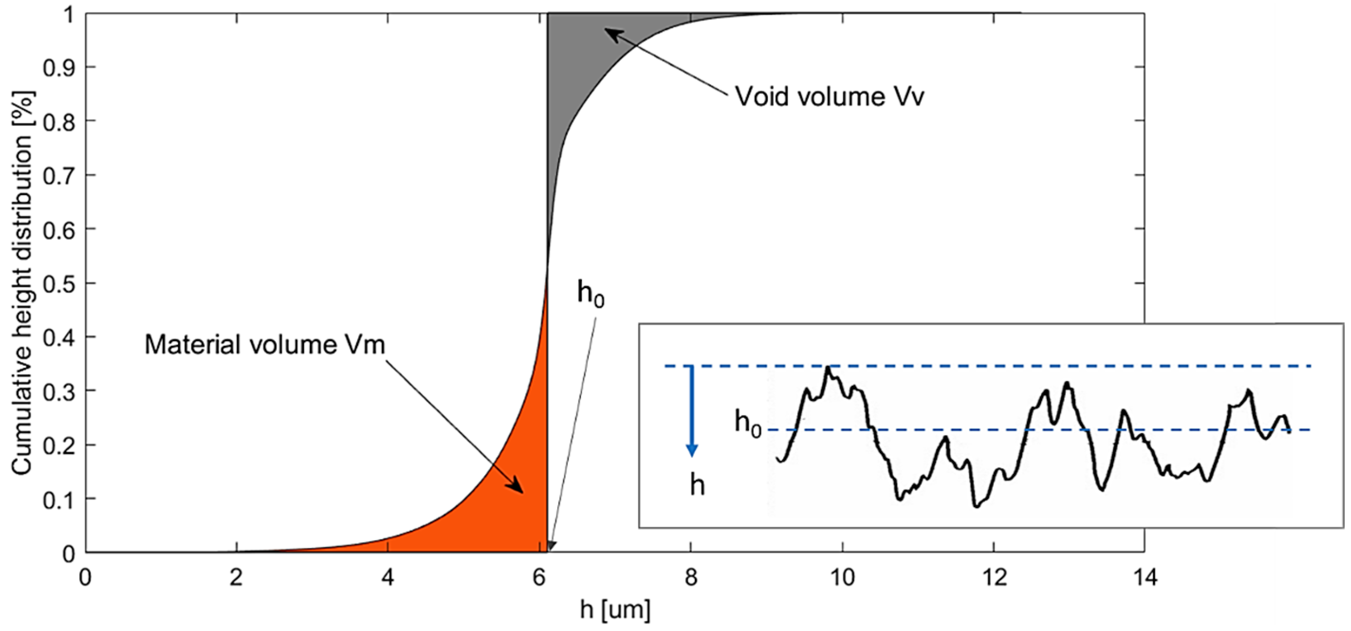
2.4. Wear Volume Calculation
3. Results and Discussion
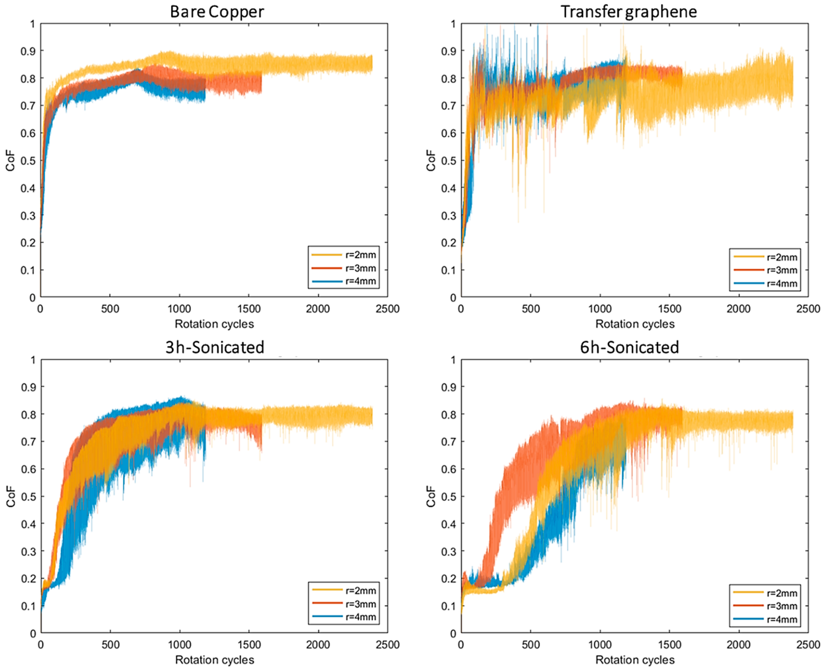
3.1. Friction
3.2. Wear
3.3. Direct Growth CVD
4. Conclusions
- -
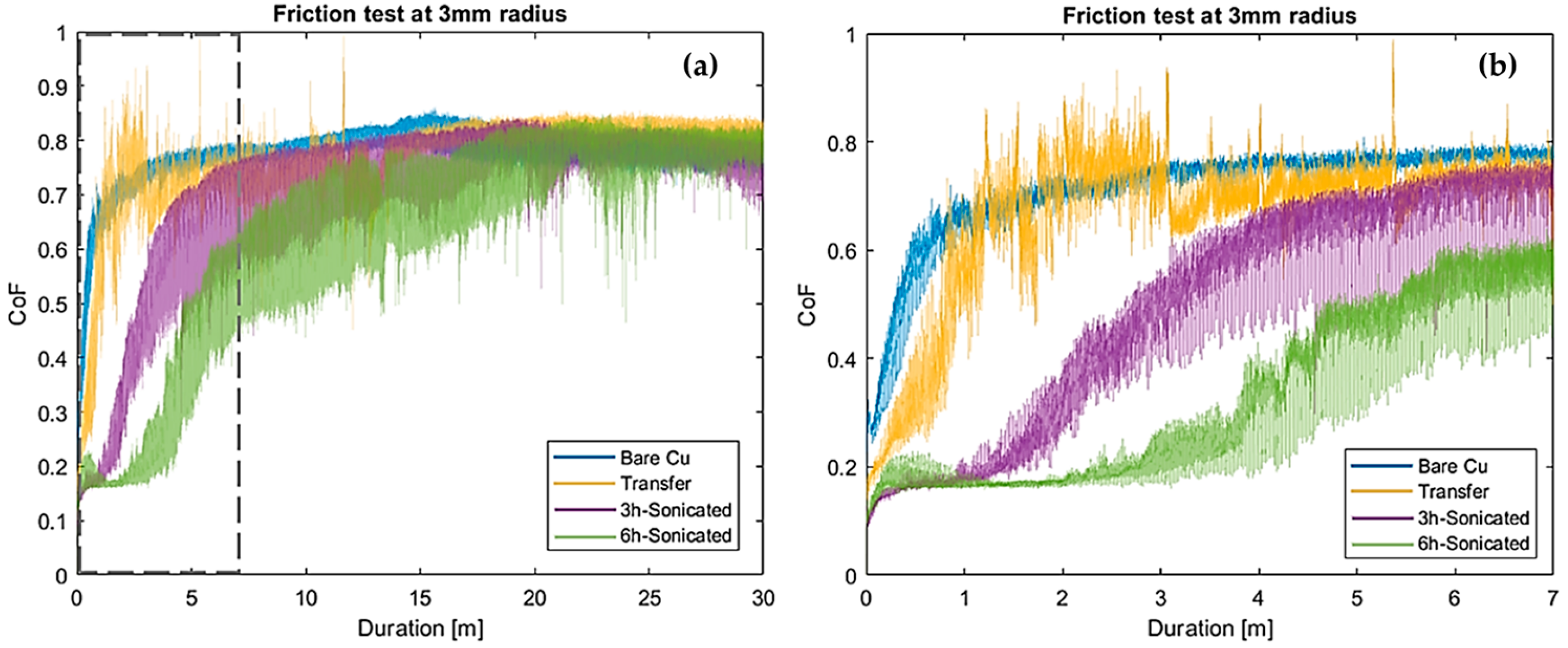
- Self-assembled graphene nano-coatings lasted longer with duration up to 1/6th of the total sliding distance of the test in the case of 6 h-sonicated graphene;
- -
- The CoF dropped from 0.6–0.7 to 0.15–0.25 in the presence of graphene, with a maximum reduction by 78% in the case of 6 h-sonicated graphene. However, this beneficial effect endured as long as the carbon nano-sheet withstood the tearing-off effect of the counter body sliding against it;
- -
- 6 h-sonicated graphene also produced a beneficial 31% reduction of the overall average friction value of the test, despite the short lifetime of the nano-coating;
- -
- The reduction in the average wear volume of copper was remarkable in the case of self-assembled graphene coatings (UGFs). The reduction was about 36% and 40% for the 3 h-sonicated and 6 h-sonicated coatings compared to the bare copper, respectively;
- -
- Transferred CVD graphene showed no benefits on friction and produced a detrimental increase of wear volume, which was never reported in the previous literature.
- -
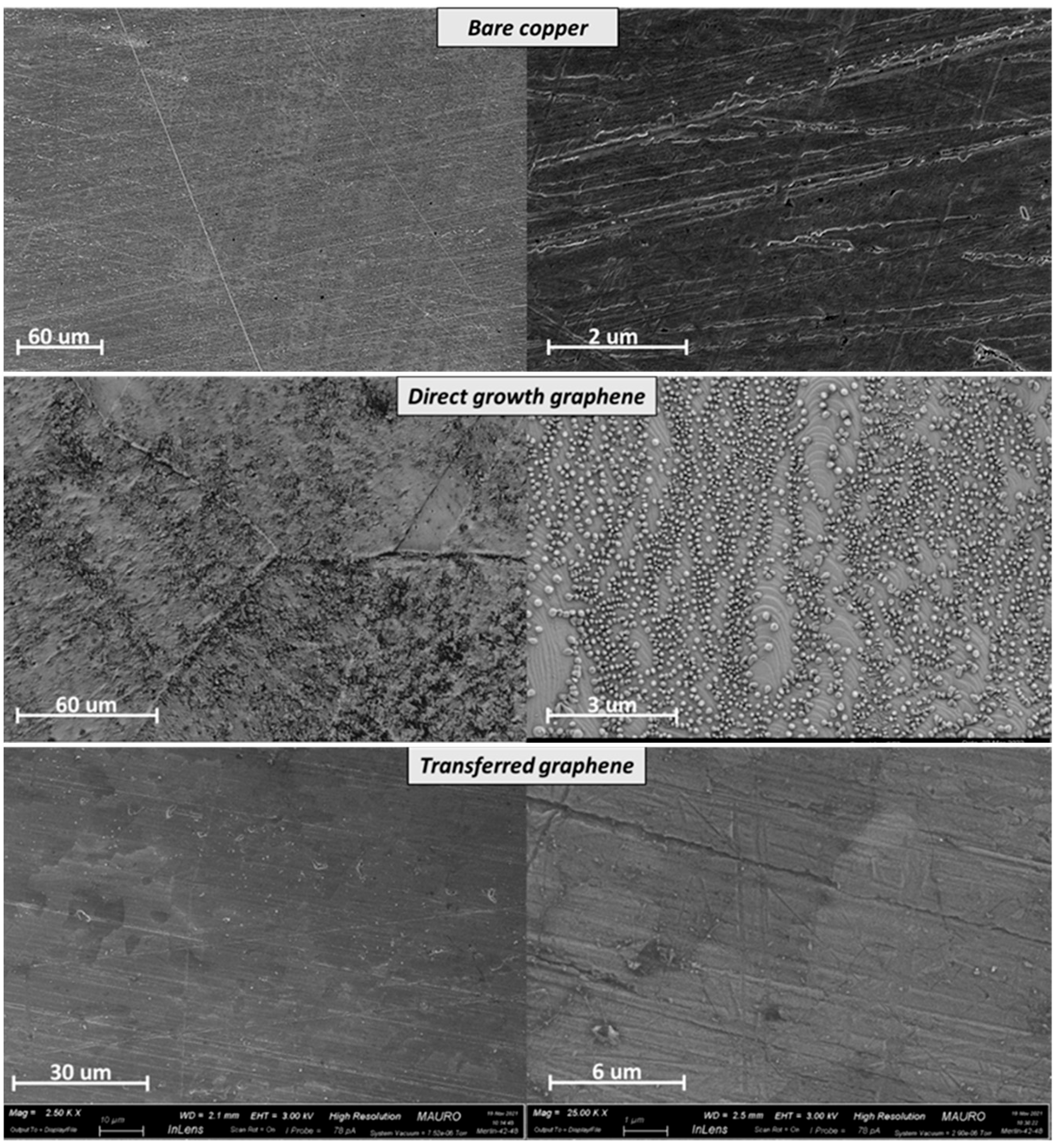
- The morphological analysis of wear tracks suggested that abrasion had a role in the presence of the transferred graphene layer, while tribo-oxidation dominated in the presence of self-assembled graphene;
- -
- The deposition of direct growth graphene on copper samples failed due to issues likely related to the use of a bulk catalytic body rather than a thin copper foil. Direct growth of CVD graphene on copper samples could not be compared to transferred CVD graphene.
- (1)
- Graphene synthesised through different production methods may contribute to activate different wear mechanisms at the sliding interface;
- (2)
- Graphene obtained from the self-assembly of GNPs is the most promising graphene production method for tribological applications in industry, despite its defective and uneven carbon structure;
- (3)
- Ultra-thin, high-purity, and low-defect structures like transferred CVD graphene are of little interest for macroscale friction and wear applications where gross sliding dominates. It turned out to be overly thin and weak;
- (4)
- The main benefits of self-assembled graphene are its increased thickness and the ability to promote a lubricious third layer at the steel-copper interface;
- (5)
- The synthesis of the direct growth of CVD graphene on bulk metal substrates, which is a promising way to reduce the cost of CVD graphene, needs further investigation to optimize the deposition process route.
Author Contributions
Funding
Institutional Review Board Statement
Informed Consent Statement
Data Availability Statement
Acknowledgments
Conflicts of Interest
References
- Uzoma, P.C.; Hu, H.; Khadem, M.; Penkov, O.V. Tribology of 2D Nanomaterials: A Review. Coatings 2020, 10, 897. [Google Scholar] [CrossRef]
- Spalvins, T. Coatings for wear and lubrication. Thin Solid Film. 1978, 53, 285–300. [Google Scholar] [CrossRef]
- Zhu, M.; Zhou, Z. An investigation of molybdenum disulfide bonded solid lubricant coatings in fretting conditions. Surf. Coat. Technol. 2001, 141, 240–245. [Google Scholar] [CrossRef]
- Friedrich, K.; Schlarb, A. Tribology of Polymeric Nanocomposites: Friction and Wear of Bulk Materials and Coatings; Elsevier: Amsterdam, The Netherlands, 2011. [Google Scholar]
- Krishna, P.V.; Srikant, R.; Rao, D.N. Solid lubricants in machining. Proc. Inst. Mech. Eng. Part J 2011, 225, 213–227. [Google Scholar] [CrossRef]
- Huai, W.; Zhang, C.; Wen, S. Graphite-based solid lubricant for high-temperature lubrication. Friction 2021, 9, 1660–1672. [Google Scholar] [CrossRef]
- Liu, X.-L.; Cai, Z.-B.; Xiao, Q.; Shen, M.-X.; Yang, W.-B.; Chen, D.-Y. Fretting wear behavior of brass/copper-graphite composites as a contactor material under electrical contact. Int. J. Mech. Sci. 2020, 184, 105703. [Google Scholar] [CrossRef]
- Liu, X.; Cai, Z.; Liu, S.; Wu, S.; Zhu, M. Influence of Wear Test Parameters on the ElectricalContact Performance of Brass Alloy/Copper Contactors under Fretting Wear. JMEPEG 2019, 28, 817–827. [Google Scholar] [CrossRef]
- Parka, C.; Jungb, D.; Chunc, E.-J.; Ahna, S.; Jangd, H.; Kimb, Y.-J. Effect of laser shock peening without coating on fretting corrosion of copper contacts. Appl. Surf. Sci. 2020, 514, 145917. [Google Scholar] [CrossRef]
- Siddaiah, A.; Kasar, A.K.; Khosla, V.; Pradeep, L. Menezes, In-Situ Fretting Wear Analysis of Electrical Connectors for Real System Applications. J. Manuf. Mater. Process. 2019, 3, 47. [Google Scholar] [CrossRef]
- Schoff, C. Coatings clinic: Electrical properties II—Conductivity of solid coatings. CoatingsTech 2007, 4, 80. [Google Scholar]
- Islam, A.; Mukherjee, B.; Sribalaji, M.; Rahman, O.A.; Arunkumar, P.; Babu, K.S.; Keshri, A.K. Role of hybrid reinforcement of carbon nanotubes and graphene nanoplatelets on the electrical conductivity of plasma sprayed alumina coating. Ceram. Int. 2018, 44, 4508–4511. [Google Scholar] [CrossRef]
- Berman, D.; Erdemir, A.; Sumant, A. Graphene: A new emerging lubricant. Mater. Today 2014, 17, 31–42. [Google Scholar] [CrossRef]
- Novoselov, S. Graphene: Materials in the flatland (Nobel Lecture). Angew. Chem. Int. Ed. Engl. 2011, 50, 6986–7002. [Google Scholar] [CrossRef]
- Penkov, O.; Kim, H.-J.; Kim, D.-E. Tribology of graphene: A review. Int. J. Precis. Eng. Manuf. 2014, 15, 577–585. [Google Scholar] [CrossRef]
- Zhang, S.; Arfaei, B.; Chen, Z. Friction force reduction for electrical terminals using graphene coating. Nanotechnology 2021, 32, 035704. [Google Scholar] [CrossRef]
- Lin, F.; Xia, Y.; Feng, X. Conductive and tribological properties of TiN-Ag composite coatings under grease lubrication. Friction 2021, 9, 774–788. [Google Scholar] [CrossRef]
- Jabinth, J.; Selvakumar, N. Enhancing the mechanical, wear behaviour of copper matrix composite with 2V-Gr as reinforcement. Proc. Inst. Mech. Eng. Part J 2021, 235, 1405–1419. [Google Scholar] [CrossRef]
- SKumar, S.; Kumar, S.D.; Magarajan, U. Investigation of mechanical and wear behaviour of graphene reinforced aluminium alloy 6061 metal matrix composite. Kov. Mater. 2020, 58, 341–349. [Google Scholar]
- Zaghloul, M.M.Y.; Veidt, M.; Heitzmann, M.T. Mechanical and Tribological Performances of Thermoplastic Polymers Reinforced with Glass Fibres at Variable Fibre Volume Fractions. Polymers 2023, 15, 694. [Google Scholar] [CrossRef]
- Zaghloul, M.M.Y.; Steel, K.; Veidt, M.; Heitzmann, M.T. Wear behaviour of polymeric materials reinforced with man-made fibres: A comprehensive review about fibre volume fraction influence on wear performance. J. Reinf. Plast. Compos. 2022, 41, 215–241. [Google Scholar] [CrossRef]
- Yildiz, B.; Balkanci, A.; Ovali, I.; Ünlü, C.G. Investigation of tribological behaviours of graphene-coated journal bearing. Tribol. Mater. Surf. Interfaces 2018, 12, 177–185. [Google Scholar] [CrossRef]
- Won, M.-S.; Penkov, O.; Kim, D.-E. Durability and degradation mechanism of graphene coatings deposited on Cu substrates under dry contact sliding. Carbon 2013, 54, 472–481. [Google Scholar] [CrossRef]
- Berman, D.; Deshmukh, S.; Sankaranarayanan, S. Extraordinary Macroscale Wear Resistance of One Atom Thick Graphene Layer. Adv. Funct. Mater. 2014, 24, 6640–6646. [Google Scholar] [CrossRef]
- Berman, D.; Erdemir, A.; Sumant, A. Few layer graphene to reduce wear and friction on sliding steel surfaces. Carbon 2013, 54, 454–459. [Google Scholar] [CrossRef]
- Shi, Z.; Shum, P.; Wasy, A.; Zhou, Z.; Li, L.K.-Y. Tribological performance of few layer graphene on textured M2 steel surfaces. Surf. Coat. Tech. 2016, 296, 164–170. [Google Scholar] [CrossRef]
- Bhowmick, S.; Banerji, A.; Alpas, A. Role of humidity in reducing sliding friction of multilayered graphene. Carbon 2015, 87, 374–384. [Google Scholar] [CrossRef]
- Alami, A.H.; Aokal, K.; Olabi, A.G.; Alasad, S.; Aljaghoub, H. Applications of graphene for energy harvesting applic ations: Focus on mechanical synthesis routes for graphene production. Energy Sources Part A Recovery Util. Environ. Eff. 2021. [Google Scholar] [CrossRef]
- Knieke, C.; Berger, A.; Voigt, M. Scalable production of graphene sheets by mechanical delamination. Carbon 2010, 48, 3196–3204. [Google Scholar] [CrossRef]
- Stafford, J.; Patapas, A.; Uzo, N. Towards scale-up of graphene production via nonoxidizing liquid exfoliation methods. AIChE J. 2018, 64, 3246–3276. [Google Scholar] [CrossRef]
- Shi, P.; Guo, J.; Liang, X.; Cheng, S.; Zheng, H.; Wang, Y.; Chen, C.; Xiang, H. Large-scale production of high-quality graphene sheets by a non-electrified electrochemical exfoliation method. Carbon 2018, 126, 507–513. [Google Scholar] [CrossRef]
- Mohammadi, S.; Kolahdouz, Z.; Darbari, S.; Mohajerzadeh, S.; Masoumi, N. Graphene formation by unzipping carbon nanotubes using a sequential plasma assisted processing. Carbon 2013, 52, 451–463. [Google Scholar] [CrossRef]
- Chen, Y.; Zhao, H.; Sheng, L. Mass-production of highly-crystalline few-layer graphene sheets by arc discharge in various H 2-inert gas mixtures. Chem. Phys. Lett. 2012, 538, 72–76. [Google Scholar] [CrossRef]
- Shin, K.-Y.; Hong, J.-Y.; Jang, J. Micropatterning of graphene sheets by inkjet printing and its wideband dipole-antenna application. Adv. Mater. 2011, 23, 2113–2118. [Google Scholar] [CrossRef]
- Li, X.; Cai, W.; Colombo, L.; Ruoff, R.S. Evolution of Graphene Growth on Ni and Cu by Carbon Isotope Labeling. Nano Lett. 2009, 9, 4268–4272. [Google Scholar] [CrossRef]
- Kim, K.S.; Zhao, Y.; Jang, H.; Lee, S.Y.; Kim, J.M.; Kim, K.S.; Ahn, J.H.; Kim, P.; Choi, J.Y.; Hong, B.H. Large-scale pattern growth of graphene films for stretchable transparent electrodes. Nature 2009, 457, 706–710. [Google Scholar] [CrossRef]
- Li, X.; Yang, T.; Yang, Y.; Zhu, J.; Li, L.; Alam, F.E.; Li, X.; Wang, K.; Cheng, H.; Lin, C.-T.; et al. Large-Area Ultrathin Graphene Films by SingleStep Marangoni Self-Assembly for Highly Sensitive Strain Sensing Application. Adv. Funct. Mater. 2016, 26, 1322–1329. [Google Scholar] [CrossRef]
- Mura, A.; Canavese, G.; Goti, E.; Rivolo, P.; Wang, H.; Ji, X.; Kong, J. Effect of different types of graphene coatings on friction and wear performance of aluminum alloy. Mech. Adv. Mater. Struct. 2020, 29, 539–547. [Google Scholar] [CrossRef]
- Mura, A.; Adamo, F.; Wang, H.; Leong, W.S.; Ji, X.; Kong, J. Investigation about tribological behavior of ABS and PC-ABS polymers coated with graphene. Tribol. Int. 2019, 134, 335–340. [Google Scholar] [CrossRef]
- Mura, A.; Wang, H.; Adamo, F.; Kong, J. Graphene coatings to enhance the tribological performance of steel. Mech. Adv. Mater. Struct. 2019, 28, 657–664. [Google Scholar] [CrossRef]
- Van Sang, L.; Sugimura, N.; Khajeh, K.; Washizu, H. Solid Lubricants of Combined Graphene and Iron Nanoparticles for Study of Friction and Stability. Langmuir 2022, 38, 1860–1868. [Google Scholar] [CrossRef]
- Van Sang, L.; Sugimura, N.; Washizu, H. Graphene as solid lubricant vertically buried into iron contact surface by annealing for superlubricity. Tribol. Int. 2022, 165, 107288. [Google Scholar] [CrossRef]
- Song, H.; Zhao, S.; Chen, P.; Mai, Y. Copper ions cross-linking graphene oxide nanosheet coatings towards robust solid lubricants. Diam. Relat. Mater. 2022, 130, 109453. [Google Scholar] [CrossRef]
- Savjani, N.; Mercadillo, V.O.; Hodgeman, D.; Paterakis, G.; Deng, Y.; Vallés, C.; Anagnostopoulos, G.; Galiotis, C.; Bissett, M.A.; Kinloch, I.A. Tribology of Copper Metal Matrix Composites Reinforced with Fluorinated Graphene Oxide Nanosheets: Implications for Solid Lubricants in Mechanical Switches. ACS Appl. Nano Mater. 2023, 6, 8202–8213. [Google Scholar] [CrossRef] [PubMed]
- Buzio, R.; Gerbi, A.; Bernini, C.; Repetto, L.; Silva, A.; Vanossi, A. Dissipation Mechanisms and Superlubricity in Solid Lubrication by Wet-Transferred Solution-Processed Graphene Flakes: Implications for Micro Electromechanical Devices. ACS Appl. Nano Mater. Artic. ASAP 2023, 6, 11443–11454. [Google Scholar] [CrossRef] [PubMed]
- Wang, W.; Chang, W.; Ding, S.; Qu, Y.; Gao, Y.; Wang, K. Preparation and tribological properties of multi-layer graphene/silicon dioxide composites-based solid lubricant coatings at elevated temperatures. R. Soc. Open Sci. 2023, 10, 220740. [Google Scholar] [CrossRef]
- García-Alonso, M.C.; Chico, B.; Lozano, R.M.; Escudero, M.L. Tribocorrosion behavior of graphene-based solid lubricants biofunctionalized with hyaluronic acid on CoCr surfaces. Tribol. Int. 2023, 183, 108420. [Google Scholar] [CrossRef]
- Pham, V. Direct Growth of Graphene on Flexible Substrates toward Flexible Electronics: A Promising Perspective. arXiv 2018, arXiv:1712.09714. [Google Scholar]
- Hong, J.; Shin, Y.C.; Zubair, A.; Mao, Y.; Palacios, T.; Dresselhaus, M.S.; Kim, S.H.; Kong, J. A rational strategy for graphene transfer on substrates with rough features. Adv. Mater. Weinh. 2016, 28, 2382–2392. [Google Scholar] [CrossRef]
- Copper Bars and Accessories. Available online: https://www.italweber.it/files/catalogue/pdf/14_Isoflex.pdf (accessed on 28 February 2023).
- Guermoune, A.; Chari, T.; Popescu, F.; Sabri, S.S.; Guillemette, J.; Skulason, H.S.; Szkopek, T.; Siaj, M. Chemical vapor deposition synthesis of graphene on copper with methanol, ethanol, and propanol precursors. Carbon 2011, 49, 4204–4210. [Google Scholar] [CrossRef]
- Pu, J.; Wan, S.; Zhao, W.; Mo, Y.; Zhang, X.; Wang, L.; Xue, Q. Preparation and tribological study of functionalized graphene-IL nanocomposite ultrathin lubrication films on Si substrates. J. Phys. Chem. C 2011, 115, 13275–13284. [Google Scholar] [CrossRef]
- Ullah, Z.; Riaz, S.; Li, Q.; Atiq, S.; Saleem, M.; Azhar, M.; Naseem, S.; Liu, L. A comparative study of graphene growth by APCVD, LPCVD and PECVD. Mater. Res. Express 2018, 5, 035606. [Google Scholar] [CrossRef]
- Moharana, R.; Sengar, S.S.; Badhan, B.; Rao, U.S.; Gautam, R.K.; Tyagi, R. Tribological Behaviour of Graphene Coated Bearing Steel (EN31). Phys. Conf. Ser. 2019, 1240, 012040. [Google Scholar] [CrossRef]
- Berman, D.; Erdemir, A.; Sumant, A. Reduced wear and friction enabled by graphene layers on sliding steel surfaces in dry nitrogen. Carbon 2013, 59, 167–175. [Google Scholar] [CrossRef]
- HertzWin, 3.3.1; Vink System Design & Analysis: Eindhoven, The Netherlands, 2022.
- Leach, R. Characterisation of Areal Surface Texture; Springer: Berlin/Heidelberg, Germany, 2013. [Google Scholar]
- Waterworth, A. Quantitative Characterisation of Surface Finishes on Stainless Steel Sheet Using 3D Surface Topography Analysis. Ph.D. Thesis, University of Huddersfield, Huddersfield, UK, 2006. [Google Scholar]
- Genta, G.; Maculotti, G. Uncertainty evaluation of small wear measurements on complex technological surfaces by machine vision-aided topographical methods. CIRP Ann. 2021, in press. [Google Scholar] [CrossRef]
- Maculotti, G.; Goti, E.; Genta, G.; Mazza, L.; Galetto, M. Uncertainty-based comparison of conventional and surface. Tribol. Int. 2022, 165, 107260. [Google Scholar] [CrossRef]
- Nečas, D.; Klapetek, P. Gwyddion: An open-source software for SPM data analysis. Cent. Eur. J. Phys. 2012, 10, 181–188. [Google Scholar] [CrossRef]
- Liang, H.; Bu, Y.; Zhang, J.; Cao, Z.; Liang, A. Graphene Oxide Film as Solid Lubricant. ACS Appl. Mater. Interfaces 2013, 5, 6369–6375. [Google Scholar] [CrossRef]
- Long, F.; Yasaei, P.Y.W.; Salehi-Khojin, A.; Shahbazian-Yassar, R. Anisotropic Friction of Wrinkled Graphene Grown by Chemical Vapor Deposition. ACS Appl. Mater. Interfaces 2017, 9, 20922–20927. [Google Scholar] [CrossRef]
- Paronyan, R.; Pigos, E.; Chen, G.; Harutyunyan, A.R. Formation of Ripples in Graphene as a result of Interfacial Instabilities. ACS Nano 2011, 5, 9619–9627. [Google Scholar] [CrossRef]
- Comanescu, C. Single layer graphene Raman bands modifications as result of transfer from copper foil to oxidized silicon or quartz substrates. In Proceedings of the 2016 International Semiconductor Conference (CAS), Sinaia, Romania, 10–12 October 2016; pp. 49–52. [Google Scholar]
- Huang, Z.; Chen, S.; Lin, Q.; Ji, Z.; Gong, P.; Sun, Z.; Shen, B. Microscopic Mechanisms Behind the High Friction and Failure. Langmuir 2021, 37, 6776–6782. [Google Scholar] [CrossRef]
- Lee, C.; Li, Q.; Kalb, W.; Liu, X.-Z.; Berger, H.; Carpick, R.W.; Hone, J. Frictional Characteristics of Atomically Thin Sheets. Science 2010, 328, 76–80. [Google Scholar] [CrossRef] [PubMed]
- Zeng, X.; Peng, Y.; Lang, H. A novel approach to decrease friction of graphene. Carbon 2017, 118, 233–240. [Google Scholar] [CrossRef]


| Chemical Composition | |||||||
|---|---|---|---|---|---|---|---|
| Cu | Bi | Pb | O | ||||
| 99.90% | Max 0.0005% | Max 0.005% | Max 0.040% | ||||
| Mechanical properties | |||||||
| Tensile strength | Yield strength | Elongation at break | Specific weight | Electrical resistivity | Hardness HV | ||
| 220 MPa | 160 MPa | 33% | 8.89 g/cm3 | 0.017 μΩ·m | 100 | ||
| Authors | Ref. | CoF | Testing Conditions |
|---|---|---|---|
| Shi et al. | [26] | 0.22 | Pin-on-disc; graphene-coated and textured M2 steel against stainless steel; 0.5 N load; Testing in ambient air; solution-processed graphene coating; |
| Berman et al. | [25] | 0.19 | Pin-on-disc; graphene-coated 440C steel against 440C steel; 2 N load; Testing in ambient air, in ethanol bath and with the addition of droplets of graphene solution; solution-processed graphene coating; |
| Berman et al. | [24] | 0.16–0.23 | Pin-on-disc; graphene-coated 440C steel against 440C steel; 1 N load; testing in N2 and H2; CVD graphene and solution-processed graphene coating; |
| Berman et al. | [55] | 0.2 | Pin-on-disc; graphene-coated steel against steel; 1 N to 5 N load; Testing in dry Nitrogen; solution-processed graphene coating; |
| Won et al. | [23] | 0.2 | Pin-on-disc; graphene-coated copper against stainless steel; 20 mN load; Testing in ambient air; CVD graphene; |
| Yildiz et al. | [22] | 0.19–0.4 | Flat-on-flat; graphene-coated bronze against AISI52100 steel; 10 N to 30 N load; Testing in ambient air; CVD graphene; |
| Mura et al. | [38] | 0.15–0.25 | Pin-on-disc; graphene-coated aluminum against steel; 5 N load; Testing in ambient air; CVD graphene and self-assembled graphene |
| Mura et al. | [40] | 0.15–0.2 | Pin-on-disc; graphene-coated steel against steel; 5 N load; Testing in ambient air; CVD graphene |
| [mm3] | Bare Cu | Transfer | Percolative-3 h | Percolative-6 h |
|---|---|---|---|---|
| Average volume of material loss | 0.0030 | 0.0056 | 0.0019 | 0.0018 |
| St.Dev. of the volume of material loss | 0.0009 | 0.0022 | 0.0003 | 0.0006 |
| Average volume of deposited material | 0.0024 | 0.0045 | 0.0017 | 0.0021 |
| St.Dev. of the volume of deposited material | 0.0007 | 0.0014 | 0.0001 | 0.0004 |
| Bare Cu | Transfer | Percolative-3 h | Percolative-6 h | ||
|---|---|---|---|---|---|
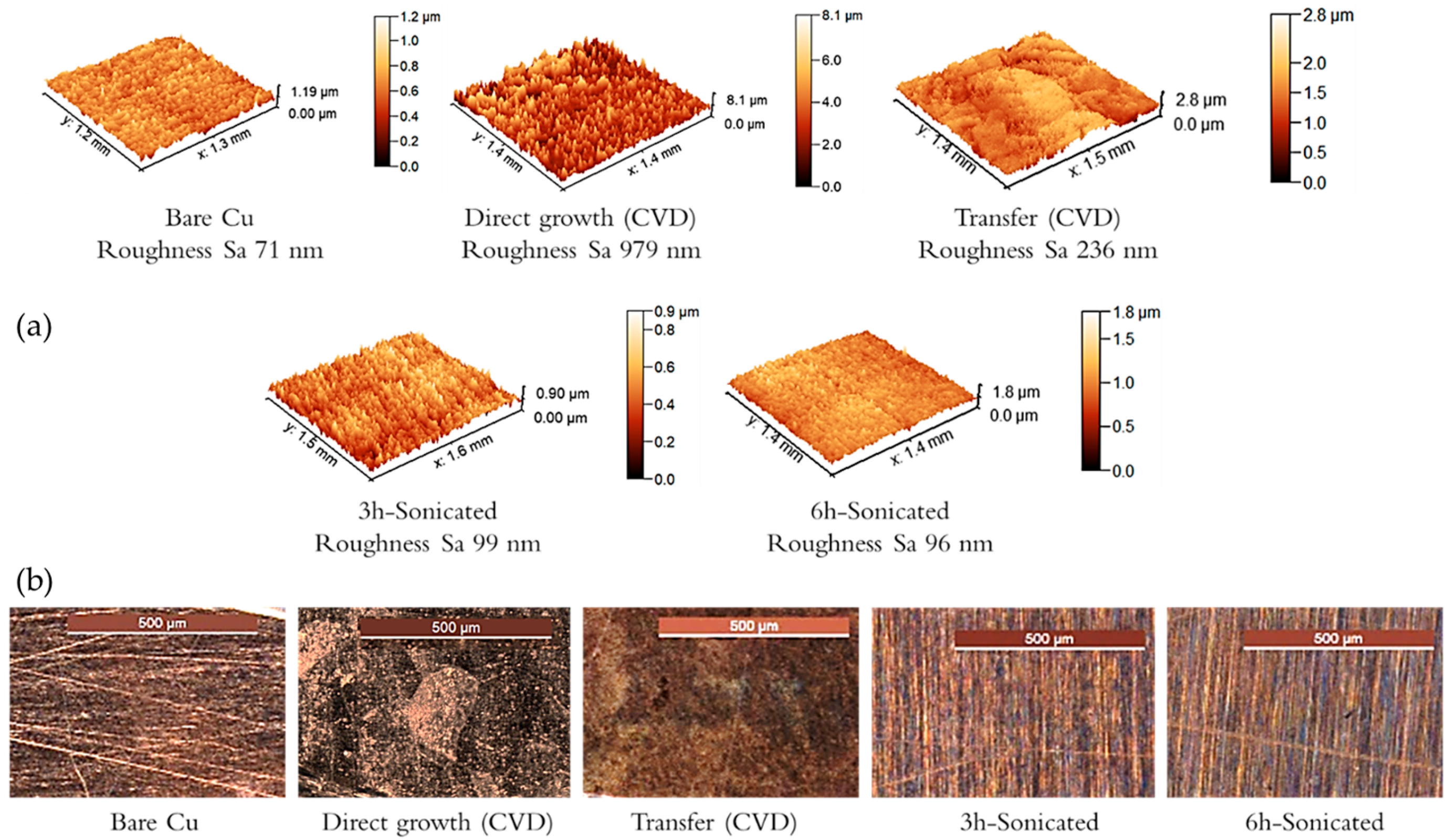
| Initial roughness value | Sa [µm] | 0.071 | 0.236 | 0.098 | 0.096 |
| Roughness inside wear tracks | Sa [µm] | 0.671 | 0.957 | 0.508 | 0.525 |
| Sq [µm] | 0.897 | 1.514 | 0.641 | 0.701 | |
| Wear track width | [µm] | 349 | 300 | 271 | 231 |
| Direct Growth | ||||
|---|---|---|---|---|
| [mm3] | [µm] | |||
| Average volume of material loss | 0.0307 | Initial roughness value | Sa | 0.979 |
| St.Dev. of the volume of material loss | 0.0101 | Roughness inside wear tracks | Sa | 1.176 |
| Average volume of deposited material | 0.0082 | Sq | 1.636 | |
| St.Dev. of the volume of deposited material | 0.0032 | Wear track width | 578 | |
Disclaimer/Publisher’s Note: The statements, opinions and data contained in all publications are solely those of the individual author(s) and contributor(s) and not of MDPI and/or the editor(s). MDPI and/or the editor(s) disclaim responsibility for any injury to people or property resulting from any ideas, methods, instructions or products referred to in the content. |
© 2023 by the authors. Licensee MDPI, Basel, Switzerland. This article is an open access article distributed under the terms and conditions of the Creative Commons Attribution (CC BY) license (https://creativecommons.org/licenses/by/4.0/).
Share and Cite
Goti, E.; Mura, A.; Wang, H.; Ji, X.; Kong, J. Comparison of the Tribological Behaviour of Various Graphene Nano-Coatings as a Solid Lubricant for Copper. Appl. Sci. 2023, 13, 8540. https://doi.org/10.3390/app13148540
Goti E, Mura A, Wang H, Ji X, Kong J. Comparison of the Tribological Behaviour of Various Graphene Nano-Coatings as a Solid Lubricant for Copper. Applied Sciences. 2023; 13(14):8540. https://doi.org/10.3390/app13148540
Chicago/Turabian StyleGoti, Edoardo, Andrea Mura, Haozhe Wang, Xiang Ji, and Jing Kong. 2023. "Comparison of the Tribological Behaviour of Various Graphene Nano-Coatings as a Solid Lubricant for Copper" Applied Sciences 13, no. 14: 8540. https://doi.org/10.3390/app13148540
APA StyleGoti, E., Mura, A., Wang, H., Ji, X., & Kong, J. (2023). Comparison of the Tribological Behaviour of Various Graphene Nano-Coatings as a Solid Lubricant for Copper. Applied Sciences, 13(14), 8540. https://doi.org/10.3390/app13148540