Article

Research on Deformation Failure Mechanism and Stability of Bedding Cataclastic Rock Slope Containing Multi-Muddy Interlayers

Faculty of Civil Engineering and Mechanics, Kunming University of Science and Technology, Kunming 650504, China
*
Author to whom correspondence should be addressed.
Appl. Sci. 2023, 13(14), 8459; https://doi.org/10.3390/app13148459
Submission received: 26 June 2023 / Revised: 18 July 2023 / Accepted: 20 July 2023 / Published: 21 July 2023
(This article belongs to the Section Civil Engineering)

Abstract

:
Based on the excavated slope of a waste incineration power plant in Yuxi, Yunnan Province, China, the finite element strength reduction method was used to investigate the variation rules of the safety factor, displacement, and deformation of the bedding cataclastic rock slope containing multi-muddy interlayers under the different conditions of number of muddy interlayers n, inclination angle θ, cohesion c, and angle of internal friction φ. Moreover, the deformation failure mechanism and stability of bedding cataclastic rock slope containing multi-muddy interlayers were revealed. The results showed that, as n increased, the maximum horizontal displacement of the slope increased, the factor of safety decreased, and the key influence on the stability of the slope was the muddy interlayers through the toe of the slope. As θ increased, the horizontal displacement of the slope first increased, then decreased, and then increased again, the safety factor first decreased, then increased, and then decreased again, and the stability of the upright laminar slope was slightly larger than that of the horizontal laminar slope. When the slope angle β was 45°, with the increase in θ, the failure mechanism of the slope manifested as a compression-shear failure, traction-sliding failure, traction-sliding-bending-shear failure, flexural deformation, and bending-buckling-collapse failure in sequence. As c increased, the slope evolved from traction-sliding failure to traction-sliding-bending-shear failure; the stability of the slope increased as c and φ increased.

1. Introduction

Slope instability (landslides and collapses) is the most common geological disaster worldwide, often resulting in casualties and property damage [1,2,3,4]. The analysis of slope stability has consistently been a focal point of research in the field of engineering geology, with many scholars having conducted extensive work and achieved significant results [5,6,7,8,9]. The presence of soft interlayers has a significant impact on many engineering projects [10,11]. The failure and instability of layered rock slopes containing these soft interlayers have become significant issues affecting engineering construction. Therefore, studying the deformation characteristics, failure mechanisms, and stability conditions of various types of layered rock slopes containing soft interlayers has significant practical implications. Zhang et al. [12] and Lu [13] used the finite element strength reduction method to analyze the impact of the height, dip angle, spacing, cohesion, internal friction angle, and slope angle of the soft interlayers on the slope displacement, safety factor, and the location of potential failure surfaces. Other researchers [14,15,16,17] employing the finite-difference-based shear strength reduction method conducted similar studies. Chai et al. [18] utilized the actual failure process analysis and strength reduction method to study the impact of the depth, dip angle, thickness, cohesion, and internal friction angle of the soft interlayers on the slope failure process, safety factor, and displacement. Liu et al. [19] utilized the theory of butterfly mutation to investigate the relationship of the safety factor of rock slopes with the dip angle, cohesion, internal friction angle, and thickness of soft interlayers.
In Yunnan Province, China, situated between the Xiaojiang fault zone and the Puduhe fault zone, bedding cataclastic rock slopes containing multi-muddy interlayers are fairly common. If not promptly reinforced after excavation, these slopes frequently destabilize. The cut slope at the Yanhe domestic waste incineration power plant in Yuxi City, Yunnan Province, is a classic example of a bedding cataclastic rock slope with multiple muddy interlayers. Slope instability resulted from improper reinforcement, leading to an increase in investment and a six-month extension of the project timeline. The authors had conducted detailed studies on the spatial distribution of the muddy interlayers and the engineering geological characteristics of the cataclastic rock mass of this slope [20,21]. Unlike soft interlayers, muddy interlayers were thinner, had lower strength, a larger Poisson’s ratio, and the surrounding rock masses above and below the muddy interlayers were more fragmented [22,23]. The form of failure and its developmental process in the rock mass containing interlayers were dependent on the interaction between the interlayers and the surrounding rock [24].
In summary, although extensive research had been conducted on the stability of layered rock slopes containing soft interlayers [25], the failure mode and stability of bedding cataclastic rock slope containing multi-muddy interlayers differed from those of layered rock slopes containing soft interlayers. Furthermore, there have been no reported studies on the stability of bedding cataclastic rock slopes containing multi-muddy interlayers.
Due to varying geological conditions and structural environments, the influencing factors of rock slopes containing multi-muddy interlayers differ, and primarily include the following categories: (1) The physical and mechanical parameters of the rock mass and structural surfaces; (2) Geometric parameters of the slope (height, angle, rock layer dip angle, structural surface spacing); and (3) Initial geo-stress, hydro-meteorological conditions, earthquakes, and anthropogenic factors. The stability of layered rock slopes often varies significantly under different geometric and physico-mechanical parameter conditions, as well as under different load combinations. The failure mechanisms of instability also differ, thus exploring the effects of numerous factors on the slope failure mechanisms is crucial. Therefore, this study primarily used the cut slope of the Yanhe domestic waste incineration power plant in Yuxi city as the basis. It selected the main geometric parameters affecting slope stability and employed the finite element strength reduction method [26,27] to investigate the variation in safety factors, displacement, and deformation rules of bedding cataclastic rock slope containing multi-muddy interlayers under different conditions of muddy interlayer number, dip angle, cohesion, and internal friction angle. The study aimed to reveal the failure mechanisms and stability characteristics of the bedding cataclastic rock slope containing multi-muddy interlayers.

2. Methods

2.1. Strength Reduction Method

With the development of computer technology, the application of finite element-based Strength Reduction Method (SRM) in slope stability analysis is becoming more and more common [28,29,30,31]. Compared with the limit equilibrium method, the finite element strength reduction method does not need to assume the location and shape of the sliding surface first, and integrates the stress, strain and displacement field characteristics of the slope. It can automatically obtain the critical slip surface of arbitrary shape and the corresponding safety factor, and can also simulate the whole process of slope instability and plastic zone expansion [32].
The basic principle of the finite element strength reduction method is to divide the shear strength parameters of the geotechnical body, i.e., the cohesion c and the internal friction coefficient f (f = tan φ, φ is the internal friction angle), by a reduction factor FOS to obtain a new set of cohesion and internal friction angle values (Equations (1) and (2)). Then, they are used as new calculation parameters for finite element calculation; when the calculation converges exactly, the corresponding FOS is the minimum factor of safety of the slope. At this time, the slope reaches the critical state and destabilization damage occurs. If FOS is further increased, the calculation will not converge [33].
c = c F O S
φ = arctan f FOS = arctan tan   φ FOS
The finite element strength reduction method cannot directly calculate the safety factor with the formula, but needs to determine whether the system enters the ultimate equilibrium state according to some damage criterion [32]. Therefore, the key to the analysis of slope stability by the finite element strength reduction method is the determination of instability-discriminant criteria. At present, there are three main types of slope instability criteria: non-convergence of the numerical iterative process of finite element, abrupt change in displacement in a characteristic part, and generalized plastic strain or equivalent plastic strain penetration [12,33]. Pei et al. [34] analyzed how the above three types of criterion are theoretically uniform and consistent and, among these three types of criterion, the finite element numerical iterative process non-convergence criterion is the most convenient to use, true, and reliable. Therefore, this criterion is chosen as the criterion for slope instability in this calculation.

2.2. Calculation Model and Parameter Selection

In actual engineering, the height of steep cataclastic rocky slopes without reinforcement was not likely to be too high, therefore, the slope (height H = 20 m) was assumed in this paper. According to the research results of Zhang et al. [32] on the calculation accuracy of the safety coefficient of slope stability, the two-dimensional calculation model was determined as shown in Figure 1. The left boundary of the calculation model was 1.5 H from the toe of the slope, the right boundary was 2.5 H from the shoulder of the slope, and the bottom of the slope extends downward by H. The slope angle β was 45°. Calculation model boundary conditions were: the bottom boundary of the slope was a fixed constraint, the left and right boundaries were constraints in the normal direction, and the ground surface of the slope was a free boundary. The calculation model consists of cataclastic rock mass and muddy interlayer; the dip angle of the interlayer was θ. Both cataclastic rock mass and muddy interlayer were simulated by solid unit, and the thickness of the interlayer was 0.05 m. In order to improve the calculation accuracy, the cell size was set to the minimum value specified by the calculation program. Both the cataclastic rock mass and the muddy interlayer are considered as ideal elastoplastic materials, and the yield criterion was adopted as the conventional Mohr–Coulomb yield criterion. The Mohr–Coulomb criterion can be expressed in terms of the invariants I 1 , J 2 , and θ σ , as shown in Equation (3):
1 3 I 1 sin   φ   + cos   θ σ - 1 3 sin   θ σ sin   φ J 2 -   cos   φ = 0
where I 1 is the first invariant of the stress tensor; J 2 is the second invariant of the stress bias; and θ σ is the stress Lodder angle.
The finite element numerical calculation was executed by the geotechnical engineering professional software PLAXIS 2D 2020, which does not consider the influence of pore water pressure and ignores the shear expansion angle (ψ = 0), i.e., the non-associated flow law was used, and the calculation results were conservative [32]. The physical and mechanical parameters of the cataclastic rock mass and muddy interlayers were determined based on the geotechnical investigation report [35]. The calculated parameters were presented in Table 1.

2.3. Scheme of the Calculation Model

In this chapter, four scenarios were proposed to be calculated to investigate the effects of layers, dip angle, cohesion, and internal friction angle of multi-layered muddied interlayer on the stability of bedding cataclastic rock slope containing multi-muddy interlayer.
Scheme 1: In order to study the impact of the number of exposed muddy interlayers, denoted as n, on the stability of bedding cataclastic rock slopes, the interlayers are arranged at equal distances starting from the slope foot, with a dip angle θ of 22°, and n is respectively 2, 4, 6, 8, and 10. Therefore, there are five scenarios in this scheme.
Scheme 2: In order to analyze the influence of the dip angle θ of multi-muddy interlayer on the stability of bedding cataclastic rock slope, the interlayer is arranged from the toe of the slope, and the interlayer spacing d is taken as 2 m. Main calculation scheme: slope angle β = 45°, θ takes 0°, 10°, 20°, 25°, 30°, 35°, 40°, 45°, 50°, 60°, 70°, 75°, 80°, 85°, and 90° in order, giving 15 arithmetic examples. Auxiliary calculation scheme: slope angle β = 30°, θ in order to take 0°, 10°, 15°, 20°, 25°, 30°, 40°, 45°, 50°, 60°, 65°, 70°, 75°, 80°, and 90°, giving 15 arithmetic examples. Slope angle β = 60°, θ in order to take 0°, 10°, 20°, 30°, 40°, 45°, 50°, 60°, 70°, 75°, 80°, 85°, and 90°, giving 13 arithmetic examples. The material parameters of the above three different inclination angle θ calculation schemes were shown in Table 1. In order to calculate all the cases properly, the shear strength parameters of both the fractured rock body and the muddied interlayer were first increased by 30% (Table 2), and then the slope angle β = 60° and θ was taken as 0°, 10°, 20°, 30°, 35°, 40°, 45°, 50°, 60°, 70°, 75°, 80°, 85°, and 90° in that order, again for 14 cases. There were 57 arithmetic cases in this program.
Scheme 3: An analysis of the effect of cohesion c of multi-muddy interlayer on the stability of bedding cataclastic rock slope. The interlayer was arranged from the toe of the slope, the inclination angle of the interlayer θ was taken as 22°, and the spacing d was taken as 2 m. The material parameters are shown in Table 1, where the internal friction angle of the muddied interlayer was taken as 16° and c was taken as 0.015 MPa, 0.02 MPa, 0.025 MPa, 0.03 MPa, 0.035 MPa, 0.04 MPa, 0.045 MPa, and 0.05 MPa, respectively, i.e., there were eight arithmetic cases in this scheme.
Scheme 4: The influence of internal friction angle φ of multi-muddy interlayer on the stability of bedding cataclastic rock slope. The material parameters are shown in Table 1, where the cohesion of the muddied interlayer was taken as 0.03 MPa and φ was taken as 8°, 10°, 12°, 14°, 16°, 18°, 20°, 22°, 24°, 26°, 28°, and 30°, respectively, i.e., there were 12 calculations in this scheme.

3. Results and Discussion

3.1. The Impact of the Number of Exposed Muddy Interlayers on the Slope Surface

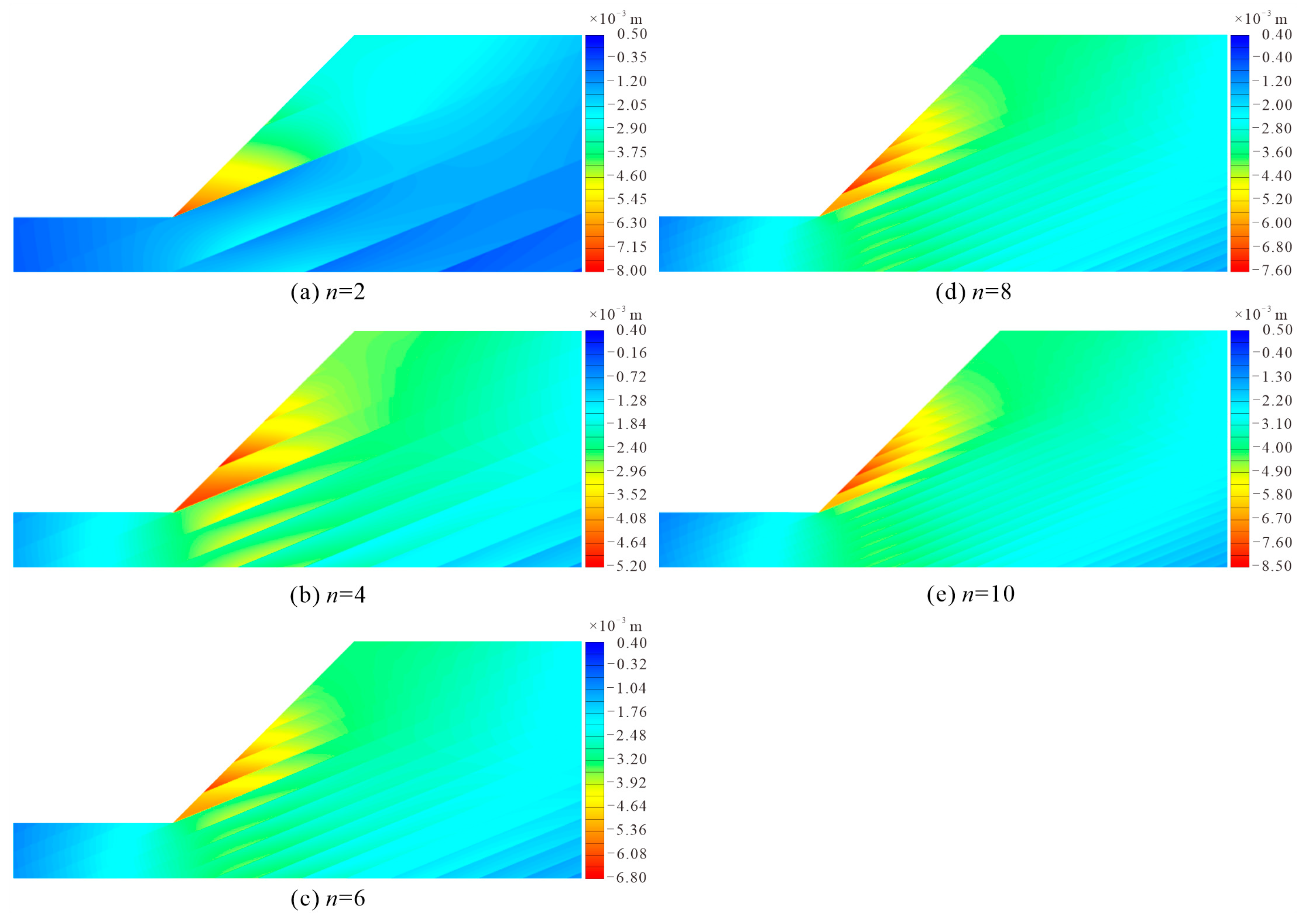
The horizontal displacement clouds (Figure 2) of the focal area of the bedding cataclastic rock slope containing multi-muddy interlayers showed the following five features: (1) The horizontal displacement of the slope was mainly negative, and only the local area was positive; (2) The absolute value of horizontal displacement near the foot of the slope was larger than that of the shoulder of the slope; (3) The absolute value of horizontal displacement of each cataclastic rock layer between the interlayer decreased gradually from the slope face to the top of the slope; (4) There were abrupt changes in the horizontal displacement clouds of the rock bodies on the upper and lower sides of the muddy interlayer, and abrupt changes from the slope face to the top of the slope became weaker and weaker, indicating that the rock bodies on both sides produced relative slip along the interlayer, and the relative slip from the proslope end of the interlayer to the top of the slope, and from the toe of the slope to the shoulder of the slope, became smaller and smaller; and (5) The maximum value of the absolute value of the horizontal displacement of the slope did not necessarily appear at the toe of the slope. When n was one or two layers, it appeared at the toe of the slope, and when n was more than two layers, it appeared at the position of the intersection of the second layer of the interlayer layer and the slope surface. The above analysis showed that the bedding cataclastic rock slope containing multi-muddy interlayers underwent multi-layered relative slip along the interlayer, and the relative slip gradually decreased from the toe to the top of the slope.
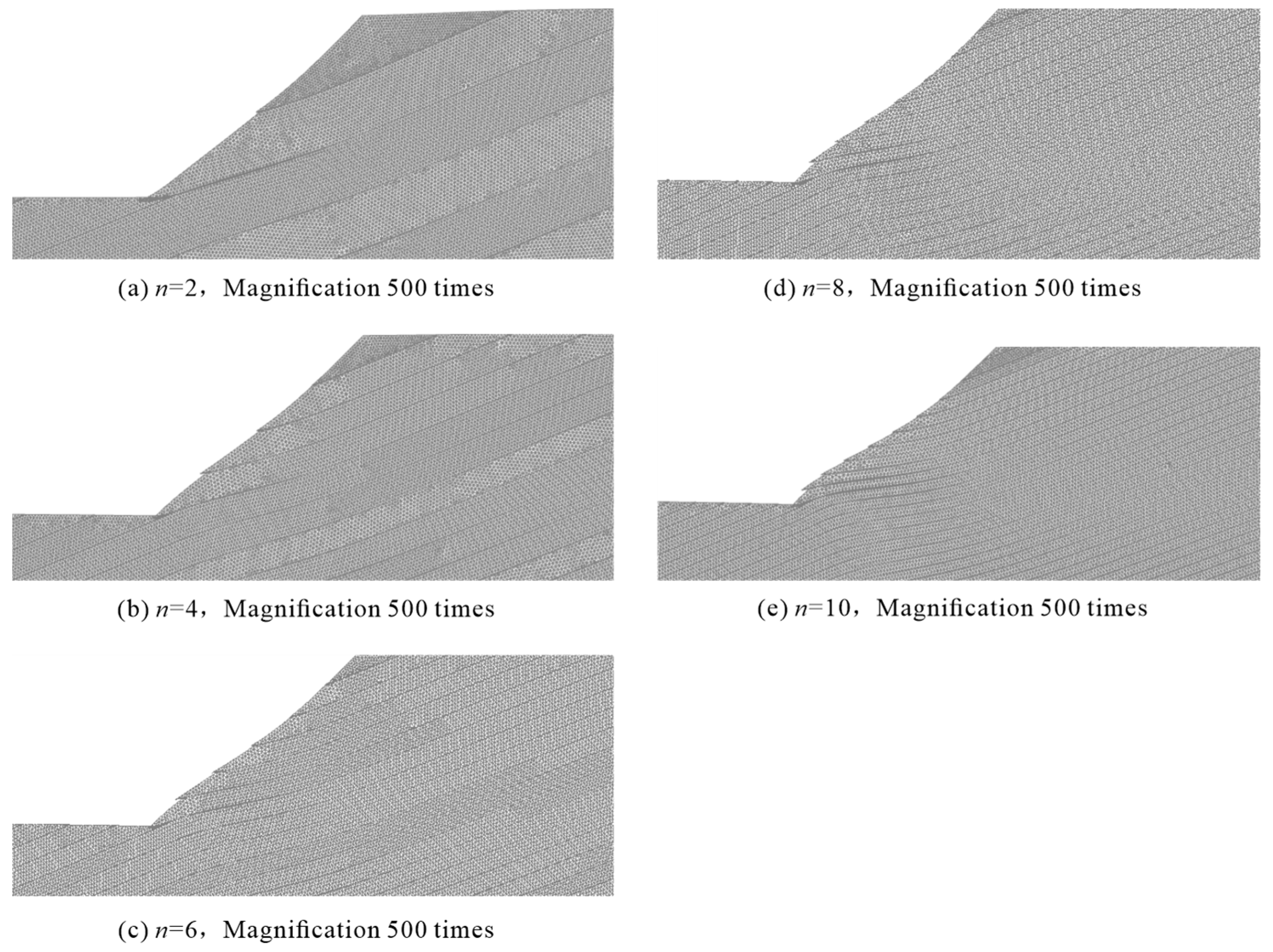
The grid deformation map (Figure 3) showed that the muddy interlayers of each computational model showed relative slip, and the relative slip was greater for the muddy interlayers near the toe of the slope. As the number of layers of muddy interlayers increased, the thickness of the cataclastic rock layer became thinner and the slope was damaged by “sliding-bending-shearing”. A similar computational model by Zhang et al. [12] did not show “sliding-bending-shearing” damage. This was because, in their calculation model, the elastic modulus of the surrounding rock of the weak interlayer was large (999 MPa) and the rock layer of the surrounding rock was thick, so its flexural stiffness was large and it was not easy to bend and deform under the action of extrusion. However, the surrounding rock in this study was fractured rock, whose elastic modulus was small, and the thickness of the cataclastic rock layer became thinner as the number of interlayer layers increased, and its flexural stiffness was small, and it was easy to bend and deform. On the whole, the destabilization mode of the upper part of the slope was “traction-sliding”, the destabilization mode of the rock near the toe of the slope was “sliding-bending-shearing”, and the destabilization mode of the bedding cataclastic rock slope containing multi-muddy interlayers was “traction-sliding-bending-shearing”.
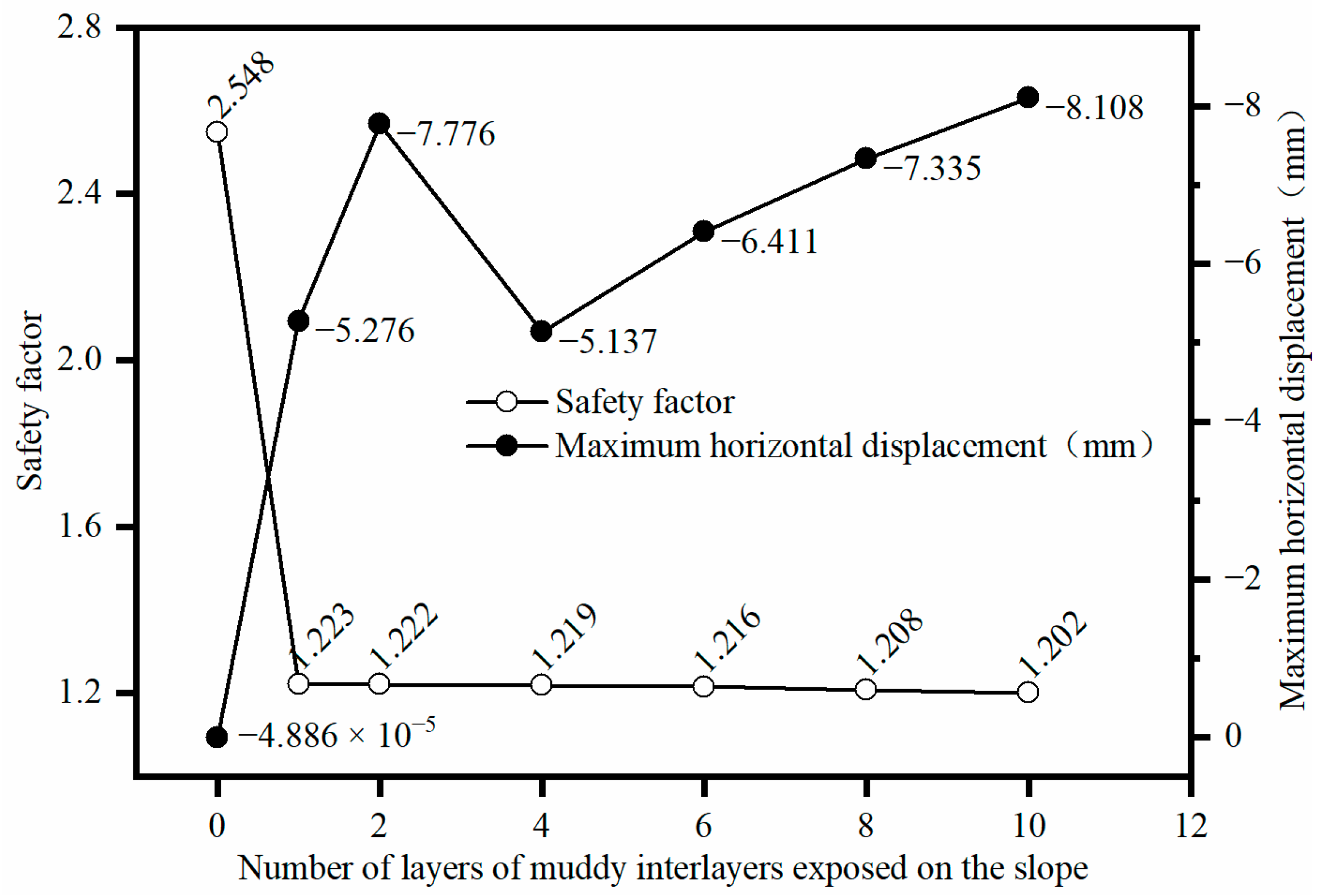
Figure 4 shows the relationship among the safety factor of the slope, the maximum horizontal displacement, and the number of layers of muddy interlayers exposed on the slope. When there was no interlayer, the maximum horizontal displacement of the slope was −4.886 × 10⁻⁵ mm; when there was only one layer of interlayer at the toe of the slope, the maximum horizontal displacement increased to −5.276 mm; when there was two layers of interlayer, the maximum horizontal displacement increased to −7.776 mm; and when there was four layers of interlayer, the maximum horizontal displacement decreased to −5.137 mm. When the interlayer increased from 4 to 10 layers, the maximum horizontal displacement slowly increased again to −8.108 mm. The maximum horizontal displacement generally increased with the number of layers of the interlayer. The slope safety factor decreased rapidly from 2.548 to 1.223 for the muddy interlayers from 0 to 1 layer, and slowly decreased to 1.202 for the increased interlayer from 1 to 10 layers. The overall safety factor decreased as the number of layers of interlayer increased, and the decisive influence on the safety factor of the slope was the muddied interlayer through the toe of the slope.
The simulation results of Zhang et al. [12] showed that the slope safety factor first decreased rapidly and then decreased slowly as the number of soft interlayers exposed on the slope surface increased. The results of Chai et al. [16] showed that the slope displacement slowly increased and the safety factor slowly decreased as the number of exposed interlayer layers on the slope surface increased. The results of this study were similar to those of Zhang et al. [12].

3.2. The Impact of the Dip Angle of Muddy Interlayers

First of all, it should be noted that, when the model with slope angle β = 60° is calculated according to the material parameters in Table 1, when θ is 30° or 40°, the numerical calculation cannot be carried out and the most unsafe inclination angle cannot be determined because of the poor self-stabilization of the slope. Therefore, the shear strength values of both the cataclastic rock mass and the muddy interlayers were increased by 30% (Table 2), and then numerical calculations were performed.
The grid deformation of the bedding cataclastic rock slope containing multi-muddy interlayers, with different dips of cis-fragmented rocky slopes at slope angle β = 30°, showed that the slope deformation damage was mainly rock bending deformation, and there was no slippage. Figure 5 gives the grid deformation diagram of the slope when the dip angle θ was 0°, 30°, 60°, and 90°.
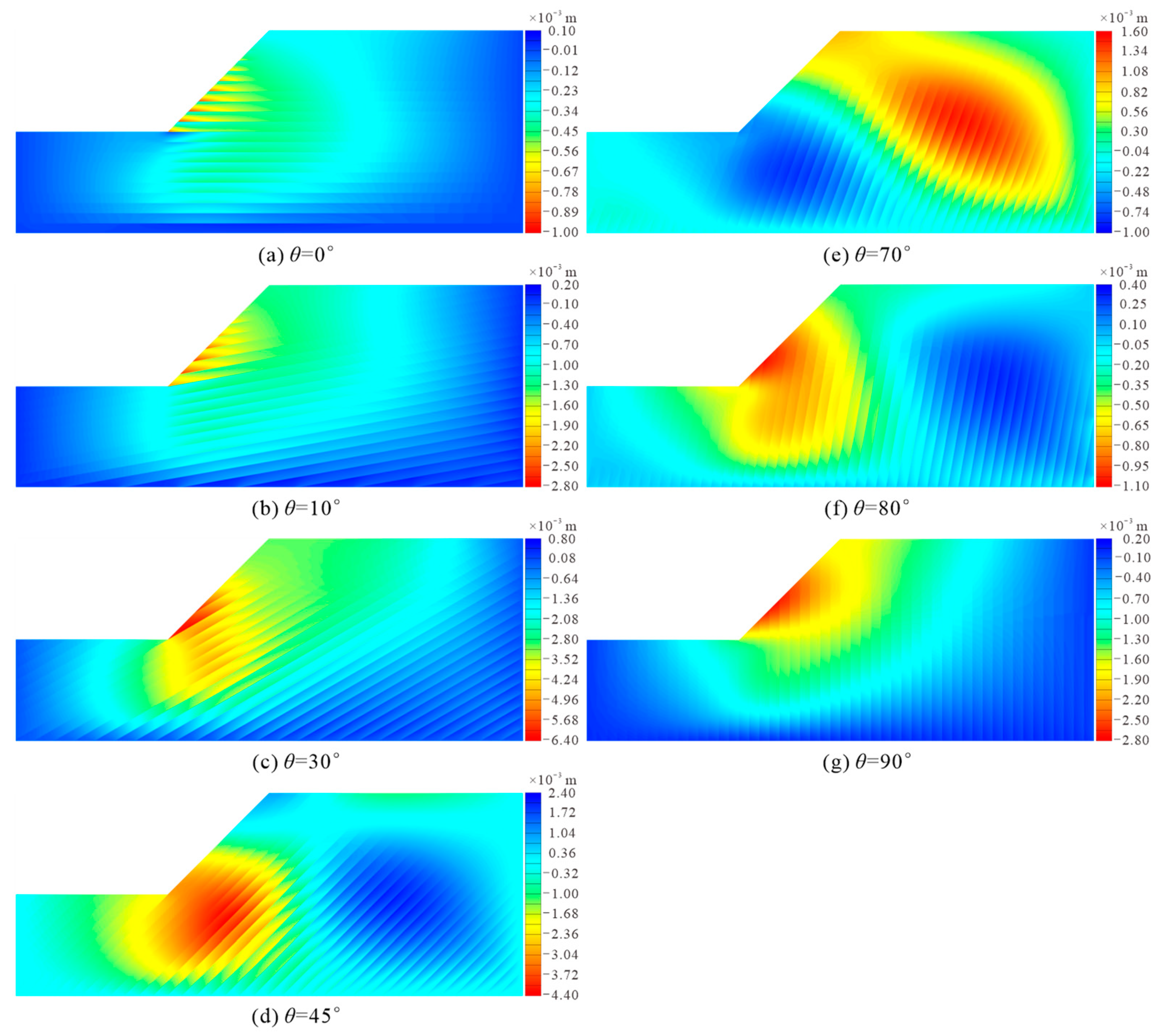
For the slope with slope angle β = 45°, when the dip angle θ of the muddy interlayers was 0° (Figure 6a), the horizontal displacement of the slope was mainly negative, and the horizontal displacement had abrupt changes along the interlayer, indicating the relative slip of the rock layer. For each cataclastic rock mass, the horizontal displacement at the bottom of the layer was significantly larger than at the top of the layer, and the relative slip phenomenon became weaker and weaker from the toe to the shoulder of the slope and from the face to the inside of the slope. When the dip angle θ of the muddied interlayer increased to 10° (Figure 6b), the overall characteristics of the horizontal displacement diagram of the slope were not significantly different from those at 0°, excepted that the maximum value of the absolute value of horizontal displacement in the X-negative direction increased by 167%, indicating that the tendency of the slope to slide toward the prograde was enhanced. θ increased from 10° to 45°, the number of layers of muddy interlayers exposed on the slope surface gradually decreased, and the horizontal displacement diagram of the slope showed the following three characteristics: (1) The maximum value of the absolute value of the horizontal displacement increased first and then decreased, with a maximum value at 25°; (2) The relative slip phenomenon between the layers was weak to strong and then decreased, with the most significant relative slip at 25°, the slip at 30° occurring mainly in the muddy interlayers through the toe of the slope (Figure 6c), and basically no relative slip in the rock layers at 45° (Figure 6d); (3) The horizontal displacement of the underlying rock layer at the toe of the slope gradually increased, and the uplift of the foot of the slope gradually became obvious. θ increased from 45° to 80°, the dip angle of the rock layer became steeper and steeper, the self-stability of the fractured rock layer was poor, and the displacement in the X-positive direction started to appear on the shoulder of the slope, and it showed a change pattern of increasing and then decreasing. And the displacement of the toe of the slope to the X negative direction and the maximum value of its absolute value showed a trend of decreasing and then increasing (Figure 6d–f). θ increased from 80° to 90°, the displacement of side slope X in the positive direction decreased, the absolute value of displacement in the negative direction increased, the displacement contour was circular, and the sliding trend of the side slope toward the critical surface was more significant (Figure 6g).
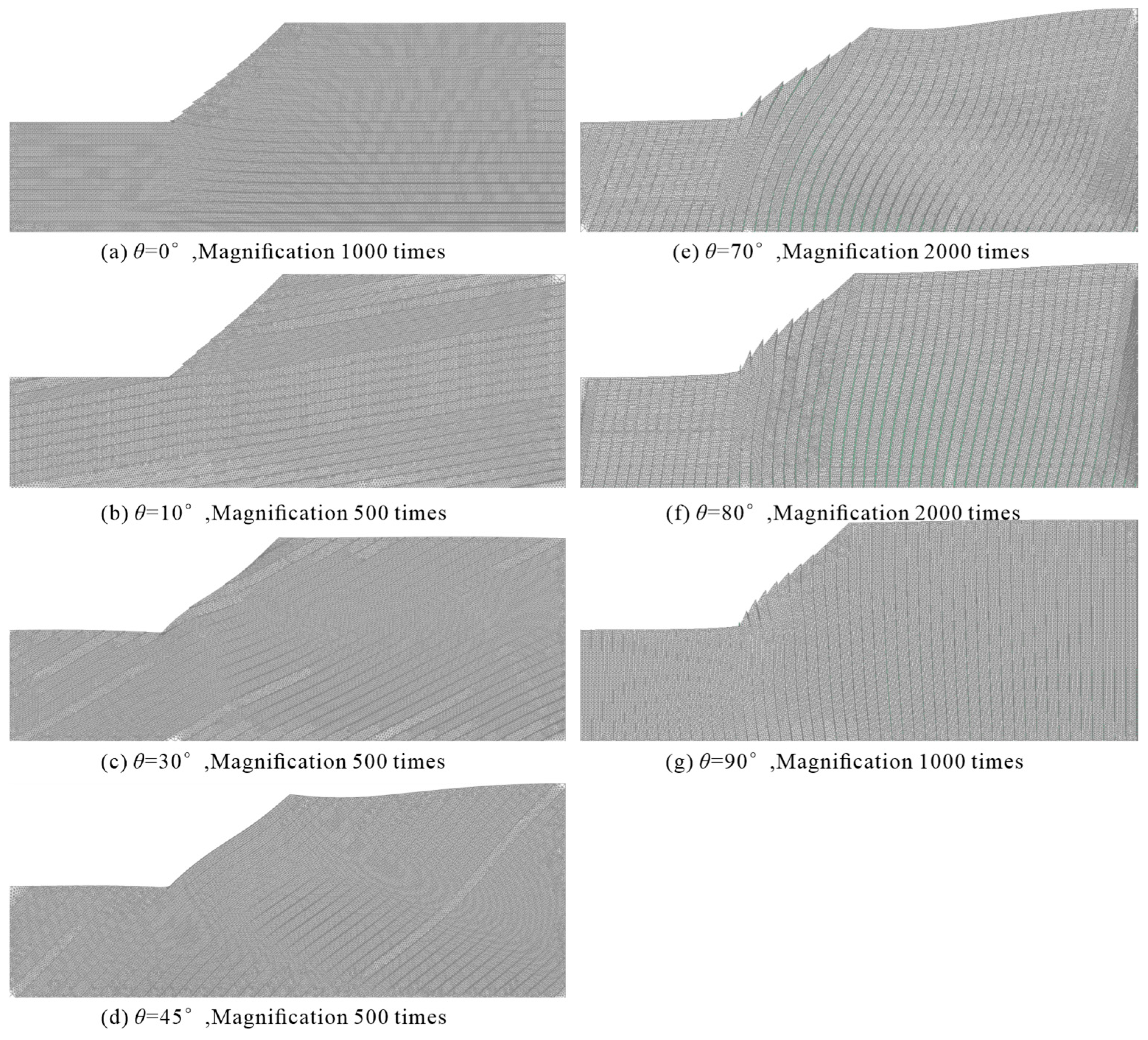
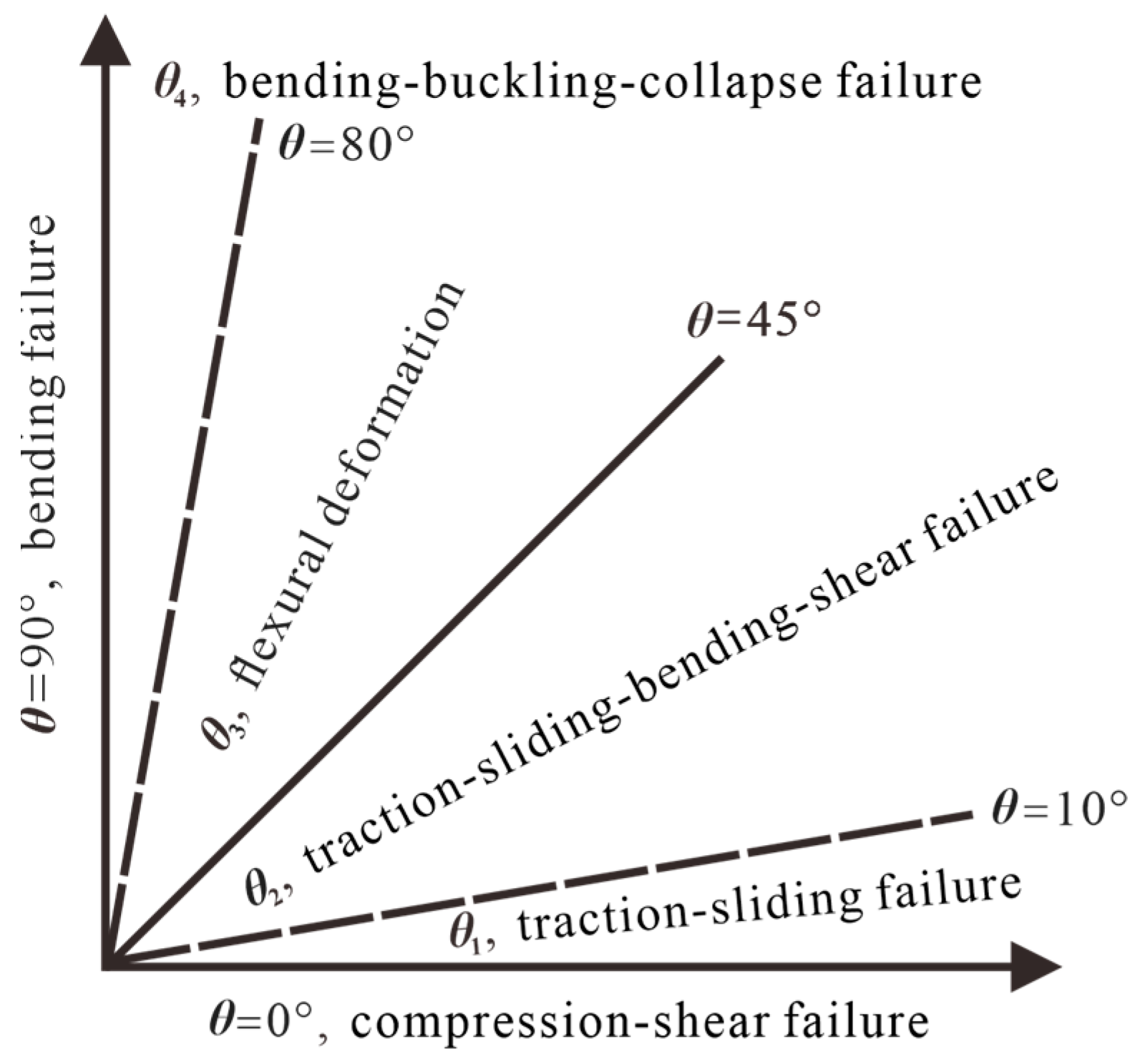
In a comprehensive analysis of horizontal displacement (Figure 6) and grid deformation (Figure 7) of β = 45° slope, the slope deformation failure exhibited the following laws: (1) When θ was 0° (horizontally bedding rock slope), the slope was compression-shear failure, i.e., under the action of its own gravity, the vertical pressure and horizontal pressure increased with depth, the compression-shear phenomenon became more obvious with increasing depth, and the shear-out displacement of the toe of the slope was the largest (Figure 7a); (2) θ in the range of (0°, 10°), the slope was damaged by “traction- sliding”, and the relative slip increased gradually from the shoulder to the toe of the slope, and the potential shear outlet location was the muddied interlayer through the toe of the slope (Figure 7b); (3) θ in the (10°, 45°) zone, the slope was damaged by “traction-sliding-bending-shear”, with uplift-bending deformation of the underlying rock layer at the toe of the slope and simultaneous slip and uplift-bending deformation of the exposed rock layer on the slope surface, especially the rock layer near the toe of the slope (Figure 7c); (4) θ in the range of [45°, 80°), the slope rock layer mainly deformed in flexure, the shoulder of the slope dipped and deformed towards the back of the slope, while the toe of the slope rose towards the surface (Figure 7d). Similar to the principle of a cantilever beam, the length of the cataclastic rock layer near the toe of the slope was short and the dumping deformation toward the back of the slope was small, while the length of the cataclastic rock layer on the shoulder of the slope was long and the dumping deformation was large, so the rock layer on the slope was separated along the muddy interlayers due to uncoordinated deformation (Figure 7e), and a tension zone was formed in the interlayer; and (5) θ was in the interval of [80°, 90°], the slope was damaged by “bending-buckling-collapse”, i.e., by the action of the slope thrust. When θ was 80°, the fractured rock layer at the toe of the slope was nearly upright, and the collapse may have occurred (Figure 7f), while when θ was 90°, the rock layer in the middle of the slope was deformed by bending, while the rock layer at the lower part (toe of the slope) was deformed by bending-buckling and collapsed to the prograde, and the tendency of the slope to collapse disaster was more obvious (Figure 7g). In a similar computational model by Zhang et al. [12], θ increased from 0° to 90° and the slope damaged modes were compression-shear failure, sliding-tensioning failure, sliding-splitting failure, bending-buckling failure, and collapse failure, in that order. In contrast to their study, traction-sliding-bending-shear failure and flexural deformation also occurred in bedding cataclastic rock slope containing multi-muddy interlayers. The relationship between slope failure modes and dip angle θ of the muddy interlayers in the rocky slopes is shown in Figure 8.
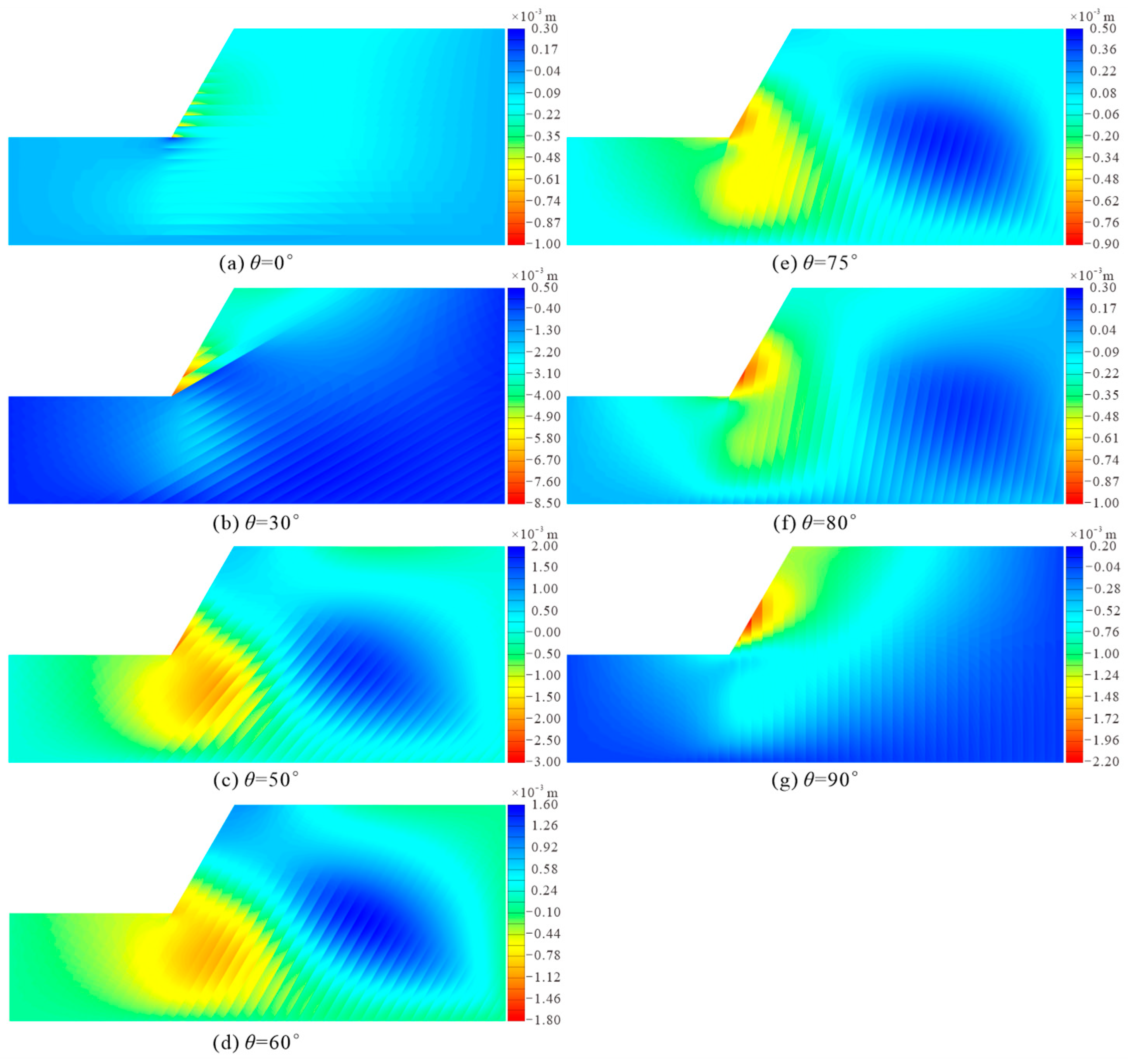
For the slope with slope angle β = 60°, when the dip angle θ of the muddy interlayers was 0° (Figure 9a), the horizontal displacement of the slope was dominated by negative values, and the horizontal displacement had abrupt changes along the interlayer, indicating the relative slip of the rock layer. For each cataclastic rock layer, the horizontal displacement at the bottom of the layer was significantly larger than at the top of the layer, and the relative slip phenomenon became weaker and weaker from the toe to the shoulder of the slope and from the face to the inside of the slope. θ increased from 0° to 50°, the number of layers of the exposed interlayer on the slope surface gradually decreased, and the horizontal displacement diagram of the slope exhibited the following two characteristics: (1) The maximum value of the absolute value of the horizontal displacement increased first and then decreased, with a maximum value at 40°; and (2) The relative slip phenomenon was weak to strong and then weakened, with the most significant relative slip phenomenon at 30° (Figure 9b), slip above 40° occurring mainly in the muddy interlayers through the toe of the slope, and slip weakening at 50° (Figure 9c). θ increased from 50° to 80°, the dip angle of the rock layer became steeper and steeper, the self-stability of the cataclastic rock layer was poor, and the displacement of the shoulder of the slope starts to appear in the X-positive direction, while the displacement of the toe of the slope went in the X-negative direction, and the maximum value of its absolute value showed a trend of first decreasing and then increasing (Figure 9d–f). θ increased from 80° to 90°, the absolute value of displacement in the negative direction of the slope increased, the displacement contour was circular, and the trend of sliding of the slope became more significant (Figure 9g).
In a comprehensive analysis of horizontal displacement (Figure 9) and grid deformation (Figure 10) of β = 60° slope, the slope deformation damage exhibited the following laws: (1) When θ was 0° (horizontally bedding rocky slope), the slope was “compression-shear” failure (Figure 10a); (2) θ in the range of (0°, 50°), the slope was “traction-sliding” failure (Figure 10b,c); (3) θ in the range of (50°, 80°), the slope rock mainly deformed in deflection (Figure 10d–f); and (4) θ in the (80°, 90°) zone, “bending-buckling-collapse” failure occurred on the slope (Figure 10g). Compared with the slope with β = 45°, the slope with β = 60° had no “traction-sliding-bending-shear” failure.
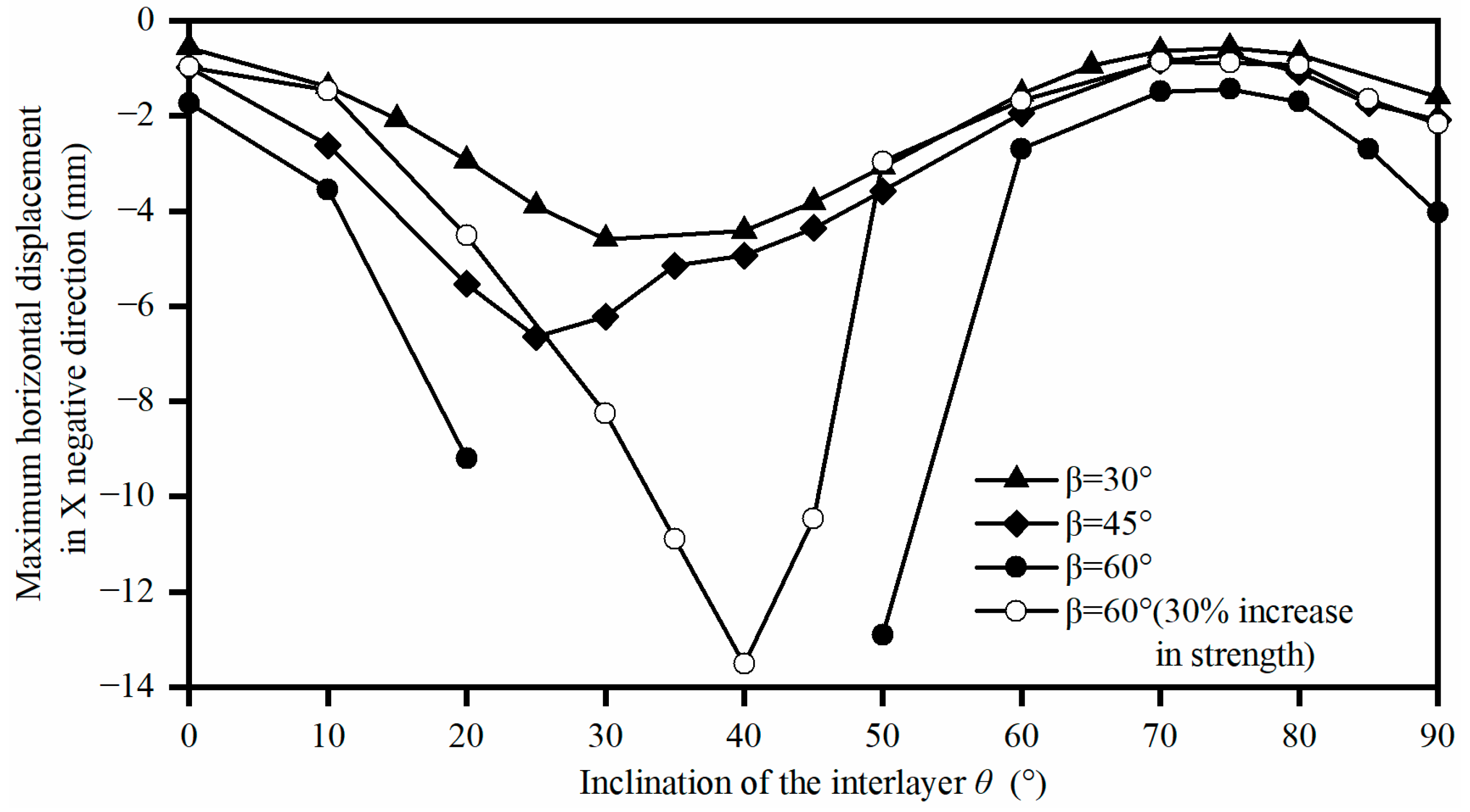
The relationship between the maximum horizontal displacement in the X-negative direction of the slope and the inclination angle θ of the interlayer is given in Figure 11, which shows the following five features: (1) θ increased from 0° to 90°, the horizontal displacements of the bedding cataclastic rock slope of the four calculation schemes showed the same pattern of change, i.e., first increasing, then decreasing, then increasing; (2) β = 30°, the θ of the horizontal displacement maximum was 30°, β = 45°, the θ of the horizontal displacement maximum was 25°, and β = 60° (30% increase in strength), the θ of the horizontal displacement maximum was 40°; (3) The horizontal displacement of upright laminated slopes was greater than that of the horizontally laminated slopes; (4) Overall, the horizontal displacement of steeply bedding rock slope was smaller than that of gently bedding rock slope; and (5) The slope angle β increased and the horizontal displacement increased.
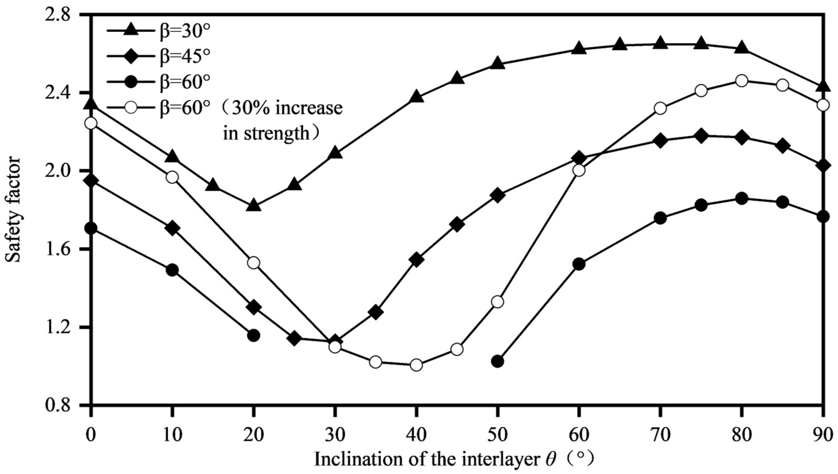
The relationship between the slope safety factor and the dip angle θ of the mezzanine is given in Figure 12, which shows the following five features: (1) θ increased from 0° to 90°, the safety coefficients of the four calculation schemes showed the same pattern of change, i.e., first decreasing, then increasing, then decreasing; (2) θ for the minimal value of safety factor was 20° when β = 30°, θ for the minimal value of safety factor was 30° when β = 45°, and θ for the minimal value of safety factor was 40° when β = 60° (30% increase in strength); (3) The safety factor of upright bedding slope was slightly greater than that of horizontal bedding slope; (4) In general, the safety factor of steeply bedding rock slope was greater than that of gently bedding rock slope; and (5) The safety factor decreased as the slope angle β increased, and the θ corresponding to the very small value of the safety factor increased. The above conclusions are consistent with Zhang et al. [12].
For rocky slopes containing a single layer of muddy interlayers, Lu [13] concluded that β = 75° and θ increased from 25° to 60°, the horizontal displacement increased and then decreased, and the safety factor decreased and then increased. The results of Liu et al. [17] showed that β = 45°, θ increased from 30° to 39°, and the horizontal displacement increased. According to Lu [13], θ for the extreme value of horizontal displacement was 45° and θ for the very small value of safety factor was also 45°, which was larger than β = 60° determined in this study when θ was both 40°. This was because the analytical model β = 75° of Lu [13] was larger than this study. Although the above laws are obtained based on the bedding rock slope containing a single soft interlayer, they coincide with the bedding cataclastic rock slope containing multi-muddy interlayers studied in this chapter in the corresponding range of dip and slope angles. However, their study also reached different conclusions from this chapter, for example, Liu et al. [17] showed that the safety factor decreased when θ increased from 30° to 39°.

3.3. The Influence of the Cohesion of the Muddy Interlayers

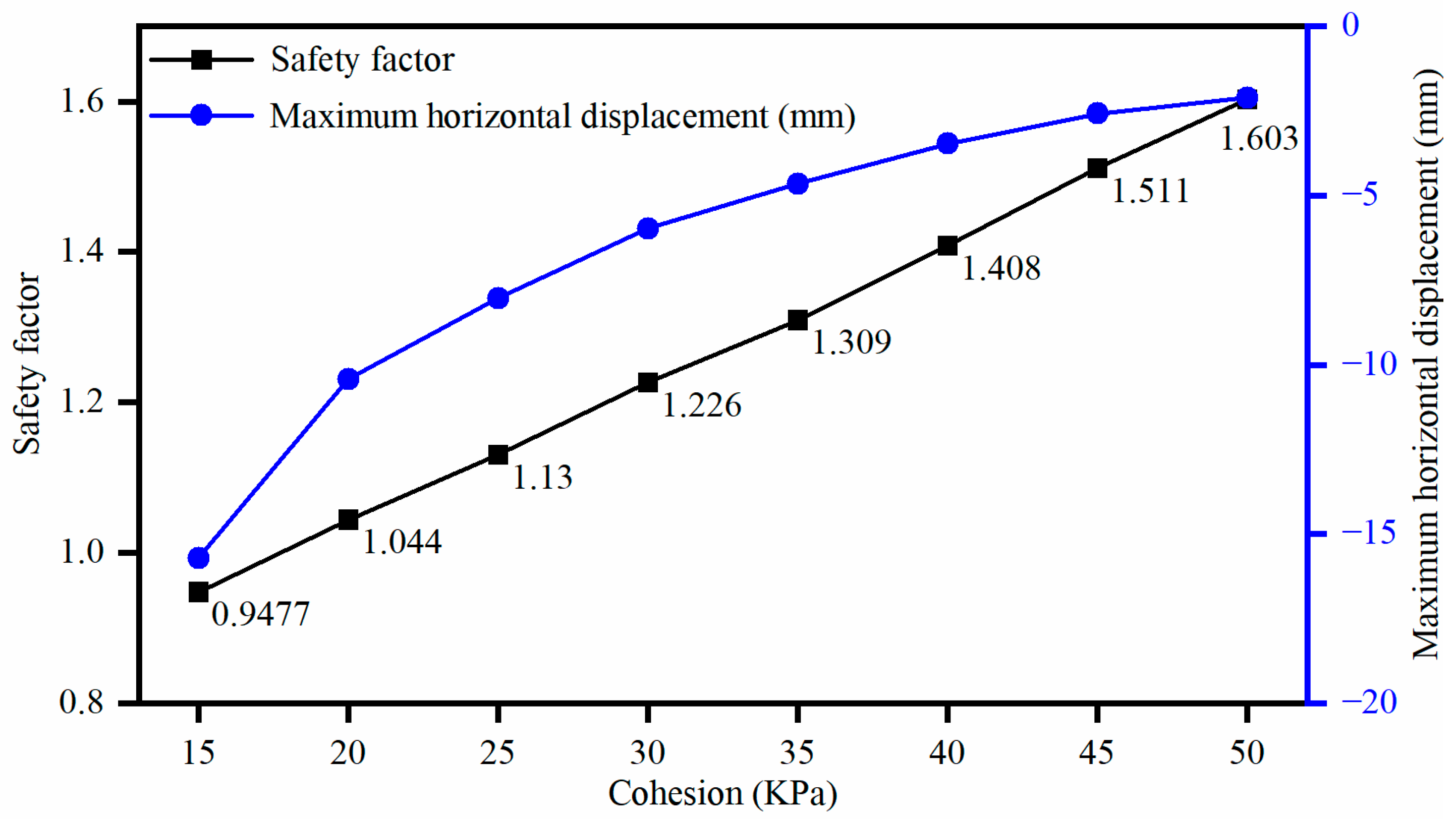
The cohesion c of the muddy interlayers increased, the stress concentration phenomenon of the maximum principal stress and maximum shear stress of the slope weakened, the stress contours became smoother and smoother (Figure 13 and Figure 14), and the maximum shear strain gradually decreased (Figure 15). The grid deformation diagram showed (Figure 16) that c increased from 0.015 to 0.02 MPa (Figure 16a,b), the slope was dominated by traction-slip damage, and the relative slip gradually decreased, and when c increased to 0.025 MPa (Figure 16c), the slope underwent traction-sliding-bending-shear failure, after which the uplift bending and relative slip weakened as c increased (Figure 16d). Figure 17 shows that the cohesion c of the muddied interlayer increased from 0.015 MPa to 0.05 MPa, the maximum horizontal displacement first decreased rapidly and then decreased slowly, the slope safety factor increased linearly from 0.95 to 1.6, and the slope stability gradually increased.
For bedding rock slope containing a single soft interlayer, Lu [13], Zhang [14], Qin [15], Zuo et al. [16], Liu et al. [17], and Chai [18] all concluded that c increases and the displacement of the slope first decreased rapidly and then decreased slowly with a linear increase in the safety factor. The analysis showed that, although the above laws were obtained based on slopes containing a single layer of weak interlayer, when the cohesion c of the weak interlayer was in the corresponding range, it coincided with the bedding cataclastic rock slope containing the multi-muddy interlayers studied in this chapter.

3.4. The Influence of the Internal Friction Angle of the Muddy Interlayers

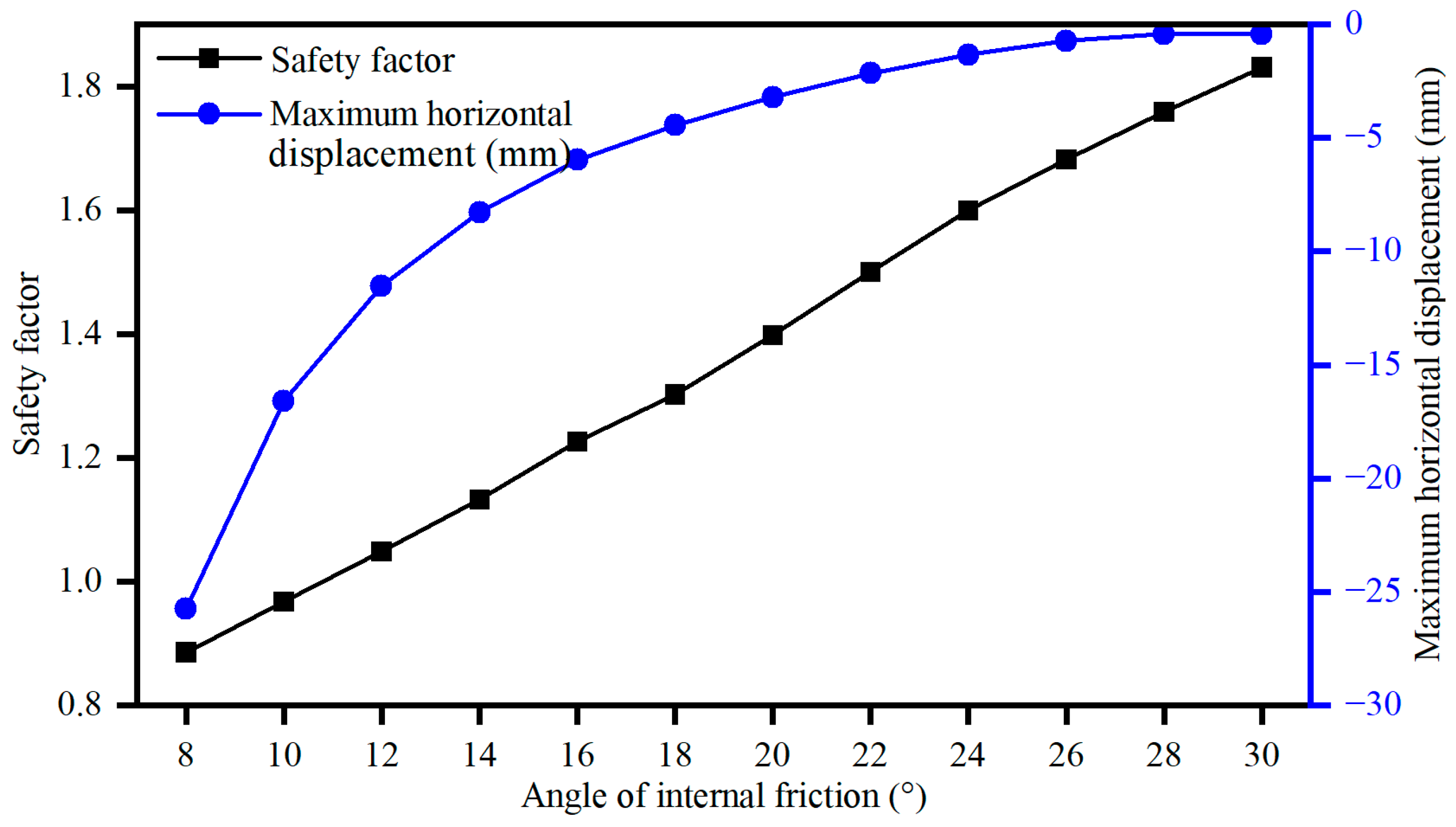
Similarly to the influence of the cohesion c of the muddy interlayers, the stress concentration phenomenon of maximum principal stress and maximum shear stress in the slope was weakened by increasing the angle of internal friction angle φ, the stress contour became smoother and smoother, and the maximum shear strain gradually decreased. The horizontal displacement diagram of the slope (Figure 18) exhibited the following characteristics: (1) Horizontal displacement was mainly in the X negative direction, the angle of internal friction angle φ increased, the maximum value of the absolute value of horizontal displacement gradually decreased, and the maximum position was always in the second layer of the mezzanine; and (2) When φ decreased, the sudden change in displacement between the exposed rock layers on the slope surface and between the underlying rock layers on the slope body was not strong, but the sudden change in displacement between the exposed rock layers on the slope surface and the underlying rock layers on the slope body was strong. When φ increased, the displacement mutation between the exposed rock layers on the slope surface and between the underlying rock layers on the slope body was enhanced, but the displacement mutation between the exposed rock layers on the slope surface and the underlying rock layers on the slope body was weakened. There was no uniform law on the influence of φ on the slope deformation damage law, as shown in Figure 18. When φ was 8°, the slope showed traction-slip damage (Figure 19a), when φ increased to 14°, the slope showed traction-sliding-bending-shear failure (Figure 19b), when φ increased to 20°, the slope was again traction-slip damage (Figure 19c), and when φ increased to 24°, the slope again showed traction-sliding-bending-shear failure (Figure 19d). Figure 20 shows that the internal friction angle φ of the muddy interlayers increased from 8° to 30°, and the maximum horizontal displacement first decreased rapidly, then decreased slowly and tended to 0. The slope safety factor increased linearly from 0.89 to 1.83, and the slope stability gradually improved.
For bedding rock slope containing a single soft interlayer, the analytical models of Zhang [14] and Qin [15] were H = 50 m, β = 60°, θ = 50°, c = 0.046 MPa, and φ = 15° to 30°. The numerical model of Liu et al. [17] was H = 50 m, β = 45°, θ = 39°, c = 0.025 MPa, and φ = 10°~25°, and they argued that the displacement of the slope first decreased rapidly and then decreased slowly as φ increased, and the safety factor increased linearly, while, in the calculation model of Lu [13], H = 50 m, β = 60°, θ = 45°, c = 0.046 MPa, φ = 20°~35°, they considered that φ increased, the slope displacement decreased first and then increased, and the safety factor increased first and then decreased.
Differing from the results in the above literature, this paper argued that the internal friction angle of the soft interlayer increased the overall slope displacement when it exceeded the internal friction angle of the interbedded surrounding rock, which was not conducive to rock stability. In order to verify this explanation, the internal friction angle of the muddied interlayer of the model calculated in this section was increased to 30°, and no slope displacement and safety factor reduction occurred.

4. Conclusions

(1) The slope underwent multilayered relative slide along the muddy interlayers, with decreasing relative slide from the toe to the top of the slope. With the increase in the number of layers of the muddy interlayers, the shear stress concentration effect of the slope became more and more significant, the maximum horizontal displacement increased, and the safety factor decreased, and the key influence on the safety coefficient of the slope was the muddy interlayers that passed through the toe of the slope. The instability mode of the bedding cataclastic rock slope containing multi-muddy interlayers was traction-sliding-bending-shear.
(2) As the dip angle θ of the muddy interlayers increased from 0° to 90°, the horizontal displacement of the slope initially increased, subsequently decreased, and then increased again, while the safety factor showed a pattern of first decreasing, then increasing, and finally decreasing again. When β was 30°, 45°, and 60° at the foot of the slope, the θ for the extreme values of horizontal displacement were 30°, 25°, and 40°, respectively, and the θ for the extreme values of the safety factor were 20°, 30°, and 40°, in that sequence. The horizontal displacement and safety factor of the upright laminated slope were greater than those of the horizontal laminated slope, the horizontal displacement of the steeply bedding rock slope was less than that of the gently bedding rock slope, and the safety factor of the steeply bedding rock slope was greater than that of the gently bedding rock slope. As β increased, the horizontal displacement increased and the safety factor decreased.
(3) When the slope angle β was 30° and θ increased from 0° to 90°, the deformation failure of the slope was primarily due to the bending deformation of the rock layer. When β was 45° and θ was 0°, the slope exhibited compression-shear failure. When θ was in the range of (0°, 10°), the slope underwent traction-sliding failure. In the interval of (10°, 45°), the slope manifested traction-sliding-bending-shear failure. When θ was in the range of (45°, 80°), the deformation of the slope rock layer was primarily flexural deformation. Finally, when θ was in the interval of (80°, 90°), the slope experienced bending-buckling-collapse failure. When β was 60° and θ was 0°, the slope exhibited compression-shear failure. When θ was in the range of (0°, 50°), the slope underwent traction-sliding failure. When θ was in the range of (50°, 80°), the primary deformation of the slope rock layer was flexural. Finally, when θ was in the interval of (80°, 90°), the slope experienced bending-buckling-collapse failure.
(4) As the cohesion c of the muddy interlayers increased, the stress concentration phenomenon, associated with the maximum principal stress and maximum shear stress of the slope, weakened, and the maximum shear strain gradually decreased. The slope evolved from traction-sliding failure to traction-sliding-bending-shear failure, and the maximum horizontal displacement decreased from a fast to slow rate, accompanied by a uniform decrease in the safety factor. As the internal friction angle φ of the muddy interlayers increased, the stress concentration phenomenon associated with the maximum principal stress and maximum shear stress of the slope decreased, and the maximum shear strain gradually decreased. There was no uniform law for the deformation and failure of the slope. The maximum horizontal displacement initially decreased rapidly, then its decrease slowed and it tended towards 0, while the safety factor decreased linearly.

Author Contributions

Conceptualization, P.Q., Y.L. and J.Z.; methodology, J.Z.; software, Y.L.; vali dation, P.Q. and Y.L.; formal analysis, P.Q.; investigation, P.Q. and J.Z.; resources, Y.L.; writing—original draft preparation, P.Q. and J.Z.; writing—review and editing, P.Q. and J.Z.; visualization, Y.L.; supervision, Y.L.; project administration, Y.L.; funding acquisition, J.Z. All authors have read and agreed to the published version of the manuscript.

Funding

This research was funded by the National Nature Science Foundation of China, grant number 41807258, Application Code: D0705, Project Category: Youth Science Fund Project, Leader: Zhang Jiaming.

Institutional Review Board Statement

Not applicable.

Informed Consent Statement

Not applicable.

Data Availability Statement

All data included in this study are available upon request through contacting the corresponding author.

Conflicts of Interest

The authors declare no conflict of interest.

References

  1. Jaiswal, A.; Verma, A.K.; Singh, T.N. Evaluation of slope stability through rock mass classification and kinematic analysis of some major slopes along NH-1A from Ramban to Banihal. J. Rock Mech. Geotech. Eng. 2023, in press. [Google Scholar] [CrossRef]
  2. Shou, K.; Wang, C. Analysis of the Chiufengershan landslide triggered by the 1999 Chi-Chi earthquake in Taiwan. Eng. Geol. 2003, 68, 237–250. [Google Scholar] [CrossRef]
  3. Dahal, R.K.; Hasegawa, S.; Yamanaka, M.; Dhakal, S.; Bhandary, N.P.; Yatabe, R. Comparative analysis of contributing parameters for rainfall-triggered landslides in the Lesser Himalaya of Nepal. Environ. Geol. 2008, 58, 567–586. [Google Scholar] [CrossRef]
  4. Wang, Y.; Fu, H.; Wan, Y.; Yu, X. Reliability and parameter sensitivity analysis on geosynthetic-reinforced slope with considering spatially variability of soil properties. Constr. Build. Mater. 2022, 350, 128806. [Google Scholar] [CrossRef]
  5. Sazid, M. Analysis of rockfall hazards along NH-15: A case study of Al-Hada road. Int. J. Geo-Eng. 2019, 10, 1. [Google Scholar] [CrossRef] [Green Version]
  6. Ansari, T.; Kainthola, A.; Singh, K.H.; Singh, T.N.; Sazid, M. Geotechnical and micro-structural characteristics of phyllite derived soil; implications for slope stability, Lesser Himalaya, Uttarakhand, India. Catena 2021, 196, 104906. [Google Scholar] [CrossRef]
  7. Singh, P.K.; Wasnik, A.B.; Kainthola, A.; Sazid, M.; Singh, T.N. The stability of road cut cliff face along SH-121: A case study. Nat. Hazards 2013, 68, 497–507. [Google Scholar] [CrossRef]
  8. Kainthola, A.; Singh, P.K.; Wasnik, A.B.; Sazid, M.; Singh, T.N. Finite Element Analysis of Road Cut Slopes using Hoek & Brown Failure Criterion. Int. J. Earth Sci. Eng. 2012, 5, 1100–1109. [Google Scholar]
  9. Siddique, T.; Sazid, M.; Khandelwal, M.; Varshney, H.; Irshad, S. Application of Slope Mass Rating and Kinematic Analysis Along Road Cut Slopes in the Himalayan Terrain. In Proceedings of Geotechnical Challenges in Mining, Tunneling and Underground Infrastructures; Springer: Singapore, 2022; Volume 10, pp. 697–708. [Google Scholar] [CrossRef]
  10. Liu, Y.; Zheng, P.; Xu, L.; Li, W.; Sun, Y.; Sun, W.; Yuan, Z. Mechanism of Roof Deformation and Support Optimization of Deeply Buried Roadway under Mining Conditions. Appl. Sci. 2022, 12, 12090. [Google Scholar] [CrossRef]
  11. Yao, E.; Li, W.; Miao, Y.; Ye, L.; Yang, Z. Study on the Influence of a Soft Soil Interlayer on Spatially Varying Ground Motions. Appl. Sci. 2022, 12, 1322. [Google Scholar] [CrossRef]
  12. Zhang, S.; Tan, Y.; Wang, C.; Wang, K. Research on deformation failure mechanism and stability of slope rock mass containing multi-weak interlayers. Rock Soil Mech. 2014, 35, 1695–1702, (In Chinese with English Abstract). [Google Scholar]
  13. Lu, B. The Research on The Stability of Rock Slope with Weak Interlayer. Doctoral Dissertation, Hebei University of Engineering, Handan, China, 2013. (In Chinese). [Google Scholar]
  14. Zhang, D. The Research on the Stability Analysis and Reinforcement Measures of Slope with Weak Interlayer. Master’s Thesis, Chongqing Jiaotong University, Chongqing, China, 2010. Available online: https://kns.cnki.net/KCMS/detail/detail.aspx?dbname=CMFD2010&filename=2010160815.nh (accessed on 10 April 2010). (In Chinese).
  15. Qin, H. Analysis of deformation characteristics and its influencing factors of slope with soft interlayer. Nat. Sci. 2011, 30, 282, (In Chinese with English Abstract). [Google Scholar]
  16. Zuo, W.R.; Liu, P. Creep properties of carbonaceous shale and slope stability analysis of soft interlayer. Hunan Commun. Sci. Technol. 2014, 40, 1–4. (In Chinese) [Google Scholar]
  17. Liu, X.; Dai, Y.; Chen, X.; Xu, Z. Stability analysis of cutting slope with carbonaceous shale weak interlayer. J. Hunan Univ. Arts Sci. (Sci. Technol.) 2015, 27, 69–74. [Google Scholar]
  18. Chai, J. The Stability Analysis of Rock Slope with Weak Interlayer under the Unloading Influence. Master’s Thesis, Qingdao University of Technology, Qingdao, China, 2016. Available online: https://kns.cnki.net/KCMS/detail/detail.aspx?dbname=CMFD201701&filename=1017018993.nh (accessed on 1 December 2016). (In Chinese).
  19. Liu, P.; Bao, T.; Yin, B. Application of butterfly catastrophe theory in stability of slope with weak interlayer. J. Guizhou Univ. (Nat. Sci.) 2019, 36, 109–112. [Google Scholar] [CrossRef]
  20. Tian, L.; Liu, W.; Zhang, J.; Gao, H. Cataclastic Characteristics and Formation Mechanism of Dolomite Rock Mass in Yunnan, China. Appl. Sci. 2023, 13, 6970. [Google Scholar] [CrossRef]
  21. Liu, W.; Zhang, J.; Wang, Z.; Xu, Z. Spatial Distribution and Geometrical Morphology of Muddy Interlayer in Rock Slopes Based on Three-Dimensional Laser Scanning Technique. J. Jilin Univ. Earth. Sci. Ed. 2021, 51, 1139–1151. [Google Scholar] [CrossRef]
  22. Zhang, J. Advances in the engineering geological properties of weak intercalation. J. Geol. Hazards Environ. Preserv. 2020, 31, 104–112. (In Chinese) [Google Scholar]
  23. Xu, D.P.; Feng, X.T.; Cui, Y.J. A simple shear strength model for interlayer shear weakness zone. Eng. Geol. 2012, 147, 114–123. [Google Scholar] [CrossRef]
  24. Xu, B.; Qian, Q.; Yan, C.; Xu, H. Stability and strengthening analyses of slope rock mass containing multi-weak interlayers. Chin. J. Rock Mech. Eng. 2009, 28, 3959–3964. [Google Scholar]
  25. Chen, Z.; Hu, X.; Bu, X. Effect of weak intercalation on failure mode of rock slopes under seismic excitation. Nat. Hazards 2020, 105, 363–381. [Google Scholar] [CrossRef]
  26. Zhang, J. State of art and trends of rock slope stability with soft interlayer. J. Eng. Geol. 2020, 28, 626–638. (In Chinese) [Google Scholar] [CrossRef]
  27. Deng, D.; Li, L.; Zhao, L. Limit equilibrium method (LEM) of slope stability and calculation of comprehensive factor of safety with double strength-reduction technique. J. Mt. Sci. 2017, 14, 2311–2324. [Google Scholar] [CrossRef]
  28. Yang, Y.; Wu, W.; Zheng, H. Investigation of slope stability based on strength-reduction-based numerical manifold method and generalized plastic strain. Int. J. Rock Mech. Min. Sci. 2023, 164, 105358. [Google Scholar] [CrossRef]
  29. Lin, H.-D.; Wang, W.-C.; Li, A.-J. Investigation of dilatancy angle effects on slope stability using the 3D finite element method strength reduction technique. Comput. Geotech. 2020, 118, 103295. [Google Scholar] [CrossRef]
  30. Sun, G.; Lin, S.; Zheng, H.; Tan, Y.; Sui, T. The virtual element method strength reduction technique for the stability analysis of stony soil slopes. Comput. Geotech. 2020, 119, 103349. [Google Scholar] [CrossRef]
  31. Peng, S.; Liao, W.; Liu, E. Pipe–soil interaction under the rainfall-induced instability of slope based on soil strength reduction method. Energy Rep. 2020, 6, 1865–1875. [Google Scholar] [CrossRef]
  32. Zhang, L.-Y.; Zheng, Y.-R.; Zhao, S.; Shi, W. The feasibility study of strength-reduction method with FEM for calculating safety factors of soil slope stability. J. Hydraul. Eng. 2003, 1, 21–26, (In Chinese with English Abstract). [Google Scholar]
  33. Zheng, Y.-R.; Zhao, S.-Y. Application of strength reduction FEM in soil and rock slope. Chin. J. Rock Mech. Eng. 2004, 23, 3381–3388, (In Chinese with English Abstract). [Google Scholar]
  34. Pei, L.; Qu, B.; Qian, S. Uniformity of slope instability criteria of strength reduction with FEM. Rock Soil Mech. 2010, 31, 3337–3341, (In Chinese with English Abstract). [Google Scholar]
  35. Zhao, Z.; Liu, W.; Wang, Z. Investigation Report on Side (Slip) Slope Management Project for Yuxi City Domestic Waste Incineration Power Generation Project; Kunming Prospecting Design Institute of China Nonferrous Metals Industry Co., Ltd.: Kunming, China, 2019. (In Chinese) [Google Scholar]
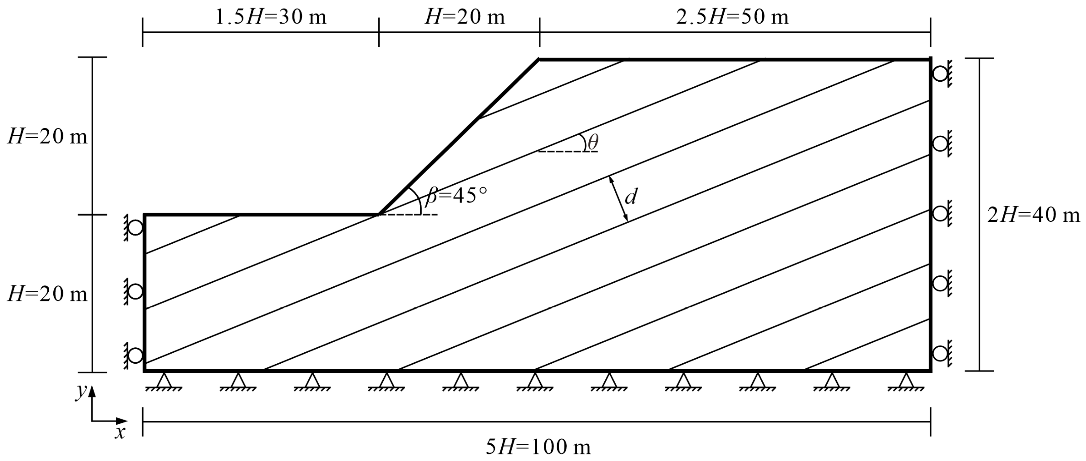
Figure 1. Two-dimensional numerical calculation model.
Applsci 13 08459 g001
Figure 2. Horizontal displacement clouds of key areas of bedding cataclastic rock slope containing multi-muddy interlayers with different layers.
Applsci 13 08459 g002
Figure 3. Grid deformation diagram of the focal area of bedding cataclastic rock slope containing multi-muddy interlayers.
Applsci 13 08459 g003
Figure 4. Relationship between safety factor, maximum horizontal displacement, and the number of exposed muddy interlayers on the slope.
Applsci 13 08459 g004
Figure 5. Grid deformation of slope at β = 30° and θ = 0°, 30°, 60°, and 90°.
Applsci 13 08459 g005
Figure 6. Horizontal displacement of the slope at β = 45° and θ = 0°, 10°, 30°, 45°, 70°, 80°, and 90°.
Applsci 13 08459 g006
Figure 7. Grid deformation of slope at β = 45° and θ = 0°, 10°, 30°, 45°, 70°, 80°, and 90°.
Applsci 13 08459 g007
Figure 8. Relationship between slope failure modes and dip angle θ of the muddy interlayers.
Applsci 13 08459 g008
Figure 9. Horizontal displacement of the slope at β = 60° and θ = 0°, 30°, 50°, 60°, 75°, 80°, and 90°.
Applsci 13 08459 g009
Figure 10. Grid deformation of slope with β = 60° and θ = 0°, 30°, 50°, 60°, 75°, 80°, and 90°.
Applsci 13 08459 g010
Figure 11. Relationship between the maximum horizontal displacement in the X-negative direction of the slope and the dip angle of the interlayer.
Applsci 13 08459 g011
Figure 12. Relationship between slope safety factor and inclination angle of interlayer.
Applsci 13 08459 g012
Figure 13. Maximum principal stress map of the focus area of the slope.
Applsci 13 08459 g013
Figure 14. Map of maximum shear stress in the focus area of the slope.
Applsci 13 08459 g014
Figure 15. Maximum shear strain diagram of the calculated model.
Applsci 13 08459 g015
Figure 16. Grid deformation diagram of the computational model (Scheme 3).
Applsci 13 08459 g016
Figure 17. Relationship between slope safety factor, maximum horizontal displacement, and cohesion of muddy interlayers.
Applsci 13 08459 g017
Figure 18. Calculated horizontal displacement diagram of the model.
Applsci 13 08459 g018
Figure 19. Grid deformation diagram of the computational model (Scheme 4).
Applsci 13 08459 g019
Figure 20. Relationship between slope safety factor, maximum horizontal displacement, and internal friction angle of muddy interlayers.
Applsci 13 08459 g020
Table 1. Physico-mechanical calculation parameters.
MaterialsDensity (g∙cm−3)Modulus of Elasticity (MPa)Poisson’s RatioCohesion (MPa)Internal Friction Angle (°)
rock body2.155000.250.1226
interlayer2.73200.350.0316
Table 2. Physico-mechanical calculation parameters (all c and φ values increased by 30%).
MaterialsDensity (g∙cm−3)Modulus of Elasticity (MPa)Poisson’s RatioCohesion (MPa)Internal Friction Angle (°)
rock body2.155000.250.15633.8
interlayer2.73200.350.03920.8
Disclaimer/Publisher’s Note: The statements, opinions and data contained in all publications are solely those of the individual author(s) and contributor(s) and not of MDPI and/or the editor(s). MDPI and/or the editor(s) disclaim responsibility for any injury to people or property resulting from any ideas, methods, instructions or products referred to in the content.