Article

Buckling-Restrained Bracing System with Ultra-High-Performance Fiber Concrete

1
Department of Civil Engineering, University Putra Malaysia, Serdang 43400, Selangor, Malaysia
2
Faculty of Environment and Technology, The University of The West England, Bristol BS16 1QY, UK
*
Author to whom correspondence should be addressed.
Appl. Sci. 2023, 13(14), 8250; https://doi.org/10.3390/app13148250
Submission received: 20 May 2023 / Revised: 26 June 2023 / Accepted: 6 July 2023 / Published: 16 July 2023
(This article belongs to the Special Issue Sustainable Concretes: Latest Advances and Prospects)

Abstract

:
Recently, buckling-restrained braces (BRBs) have been widely implemented as seismic load resistance systems in buildings to enhance their response against dynamic vibration. However, during catastrophic earthquakes, the steel core in BRB devices fully yields, which causes the BRB to lose its functionality. While the incorporation of various filler materials, such as new high-performance concretes, has the potential to enhance the performance of buckling-restrained braces (BRBs), there remains a notable gap regarding comprehensive research investigating this aspect. Therefore, this study assessed the effect of implementing ultra-high-performance concrete (UHPFRC) as filler material on BRB behavior. For this purpose, the finite element model for the proposed BRB was developed and hysteresis analysis results under incremental cyclic loads were investigated. Then, the prototype of a BRB with UHPFRC concrete was cast and experimentally tested under cyclic loads by using a dynamic actuator. Based on the testing results, a new design for a BRB device named as rubber buckling-restrained brace (RBRB) was developed, implementing hyperelastic rubber components between the steel core and UHPFRC as an additional load-bearing mechanism to enhance the device vibration dissipation capacity. Subsequently, a finite element model of the newly proposed rubber buckling-restrained brace (RBRB) was developed to assess the device’s performance. The analysis results demonstrate a notable enhancement in load capacity and energy dissipation for the RBRB device compared to conventional BRBs.

1. Introduction

Current construction techniques generally use lateral bracing systems in the form of tension-only bracing or rigid tension–compression steel bracing to increase the stiffness of structures. While conventional lateral cross-bracing can be used for both lateral excitation applications, the cyclic compressive force applied to steel braces during seismic events has resulted in the recent development of the buckling-restrained bracing (BRB) system. However, research on buckling-restrained braces (BRBs) has indicated that once the main core fails, they lose their capacity to bear additional loads. Therefore, it is crucial to consider the need for repair or replacement of BRBs after they are subject to severe excitation. One of the primary causes of failure in BRBs is attributed to their significant residual deformation resulting from their low post-yield stiffness. This characteristic can lead to the premature collapse of the brace during vibrations.
Investigations into the use of metallic yielding devices as part of the main structural system to dissipate seismic energy were first conducted in 1974 [1]. Introducing steel members with a known yield point and reliable plastic plateau to work as axial, shear, bending, or torsion-type hysteretic dampers was the main idea [2,3]. The concept of a ductile device, which is able to have a function beyond the frequent elastic limitations in cyclic loading, led to the seismic energy-dissipating systems that are used today [4]. Concentrically braced frames (CBFs), eccentrically braced frames (EBFs), and buckling-restrained braced frames (BRBFs) are three types of braces that are made in order to fulfill this need [5].
Generally, structures are subject to considerable cyclic forces during a seismic event. Buckling-restrained brace (BRB) devices are implemented in order to enhance the resistance of braced frame structures by dissipating the energy. BRBs are made of a slender steel core constantly supported by a filler material casing. After a high-intensity earthquake has occurred [6,7,8,9,10,11], the core component of the structure can undergo complete yielding and failure, resulting in the loss of its functionality. As a consequence, the structure remains unbraced, which can potentially lead to unexpected failure or collapse of the main structural elements.
Testing and evaluation are compulsory when designing and ensuring quality control. Although experimental tests can accurately assess the behavior of anti-seismic devices, they require significant financial resources and may lengthen the actual project schedules.
Numerous research studies have been conducted over the past decade, leading to the development of various types of buckling-restrained braces (BRBs). Due to the complexity of these devices, it is essential to complement numerical estimations with experimental studies for reliable results. Without proper validation, numerical estimations may not be entirely dependable. However, validated and verified models can play a crucial role in accurately predicting the behavior of BRBs, making them indispensable in the design process for these devices.
Due to the mechanical difficulties and the need to keep to the design process, mainly empirical and semi-empirical models have been proposed. Palazzo (2009) offered an analytical method for BRB rigidity requirements [12] and Hikino (2011) presented an out-of-plane-deformations stability model [13]. Zhao (2012) investigated whether bracing systems affect end rotation for global stability designs [14] and also studied the local buckling behavior of all-steel BsRBs [15]. Budaházy (2015) also worked on all-steel BRBs analytically [16].
Other researchers have developed more intricate, fundamental finite element models. These numerical models were developed to highlight specific BRB design details to illustrate behavior approximations. Takeuchi (2010) investigated the local stiffness of the hollow section in BRBs [17]. They came to the conclusion that the length of the core plate does not affect buckling behavior and provided a standard for local buckling restraint failure. Chou (2010) prepared a sandwiched BRB 3D numerical model to provide a better understanding of the compressive behavior of BRBs under buckling loading. In this model, the concrete behavior was assumed to be elastic [18]. They checked whether the BRB components affect elements such as the core plate size in terms of its behavior. Hoveidae (2012) developed an all-steel BRB 3D FEM model by focusing on the overall buckling behavior [19]. They studied the effect of the air gap between the core and the restrainer and concluded that the contact frictional magnitude coefficient had a significant effect on the behavior of the device. Razavi (2012) also developed a 3D model for all-steel BRBs with reduced lengths using the bilinear steel material model [20]. There are several researchers working on developing numerical material modeling.
The aforesaid BRB FEM models were developed using the finite element commercial software Abaqus; the concrete was modeled as an elastic material and the steel material was modeled with diverse material models, such as simple bilinear and complex combined hardening. However, in the cyclic material models, some key cyclic characteristics were not considered.
A range of models were developed to expose the cyclic BRB behavior in numerical studies using truss finite elements: an elasto-plastic bilinear model with 110% axial compressive strength of the tensile and post-yield stiffness set as zero [21]; a force–deformation bilinear relationship with post-yield stiffness set as 0.05 [22]; a force–deformation trilinear analytical model (with two inelastic truss elements in parallel) representing the BRB strength raise from isotropic hardening [23]; the Bouc–Wen smooth law [24]; the modified Ramberg–Osgood smooth law with isotropic and kinematic strain hardening as well as a yield load in compression increased by 10% [25]; the Menegotto–Pinto smooth law with kinematic and isotropic hardening [26]. All uni-axial constitutive models have their own advantages and disadvantages. Bilinear laws are uncomplicated and capture the overall BRB hysteretic behavior in cases with proper hardening rules. Nevertheless, these models do not have the ideal response efficiency and the estimate of the actual load-deformation behavior is not sufficient and is enhanced just to a limited extent by tri-linear laws.
Nevertheless, the conventional BRBs had some restrictions which have limited the extensive acceptance of BRBFs in the design community. For instance, the yielding core element of BRB supposed to dissipate hysteretic energy during an earthquake event. This absorbed energy is capable of causing cumulative damage, reducing fatigue life and even ruptures in the element, possibly compromising BRB efficiency for following earthquakes. Another issue is the difficulty of detecting and tracking damage in a core element of a conventional BRB aftermath of a severe earthquake, which can be destructive. Furthermore, the buckling–restraining element of a well-designed ordinary BRB should remain elastic when damages occur in its restrained yielding segment. However, it is inconvenient to reuse the buckling–restraining elements of ordinary BRBs, which does not help achieve the sustainable design objective.
Most studies in the literature focused on investigation of the BRB behavior by changing the core material, and the design effect of filler material was neglected. Hence, Esfandairi (2023) conducted an experimental test, focusing on the effect of conventional concrete mixed with steel, micro silica, fly ash and polypropylene and their mixture percentage on a BRB performance. The findings of this research indicated that conventional concrete with steel fibers yielded the most favorable outcome, enhancing the compressive capacity of BRBs by 25% [27].
Thus, this study focused on investigating the effect of filler materials on the behavior and performance of BRB through numerical and experimental studies to develop a new BRB system using UHPFRC filler due to its advantages as a sustainable material that contributes to prolonging the service life of reinforced concrete structures and making them more environmentally friendly [28]. Furthermore, in this research, a newly designed rubber buckling-restrained brace (RBRB) by utilizing rubber element to enhance the BRB system performance is proposed through FEA simulation.

2. Implementing UHPFRC Concrete in BRB Device

The functionality of the BRB mechanism relies on the tensile force exerted by the steel core and the role of the concrete filler in preventing buckling of the steel core under compression. As a result, the concrete component plays a crucial role in the device’s ability to withstand compressive forces.
Due to the recent development of various high-strength types of concrete, the implementation of these new concrete types can significantly impact the performance of the BRB systems. Therefore, the main objective of this study is to focus on the implementation of ultra-high-performance fiber concrete (UHPFRC) in BRB and investigate its behavior under cyclic loads.
To achieve this objective, a finite element model of the BRB device using UHPFRC material was created using the ABAQUS finite element package. Nonlinear analysis was performed by applying incremental displacement with 1 mm amplitude, as depicted in Figure 1. The purpose of this analysis was to simulate the behavior of the BRB device under cyclic loading conditions. By conducting this analysis, the force–displacement results were obtained, which represent devices’ behavior and provide insights into its performance under different loading scenarios.
In the process of designing a BRB, its core components were divided into two main sections with a 40% ratio of the core length for the plastic section and 60% for the elastic section [29]. Then, the core element was inserted inside the concrete component, considering a gap to allow the core to have local buckling, and in the final step, a steel tube restrainer which is a hollow section steel tube and provides sufficient confinement for the concrete component was designed.
Initial finite element geometries modeling of the device was completed to provide tentative verification that the device behaves in an expected manner. Table 1 represents the details and specifications of the BRB model using UHPFRC concrete as the filler material. The considered steel core section area was 300 mm2 with total length of 1500 mm as shown in Figure 2.

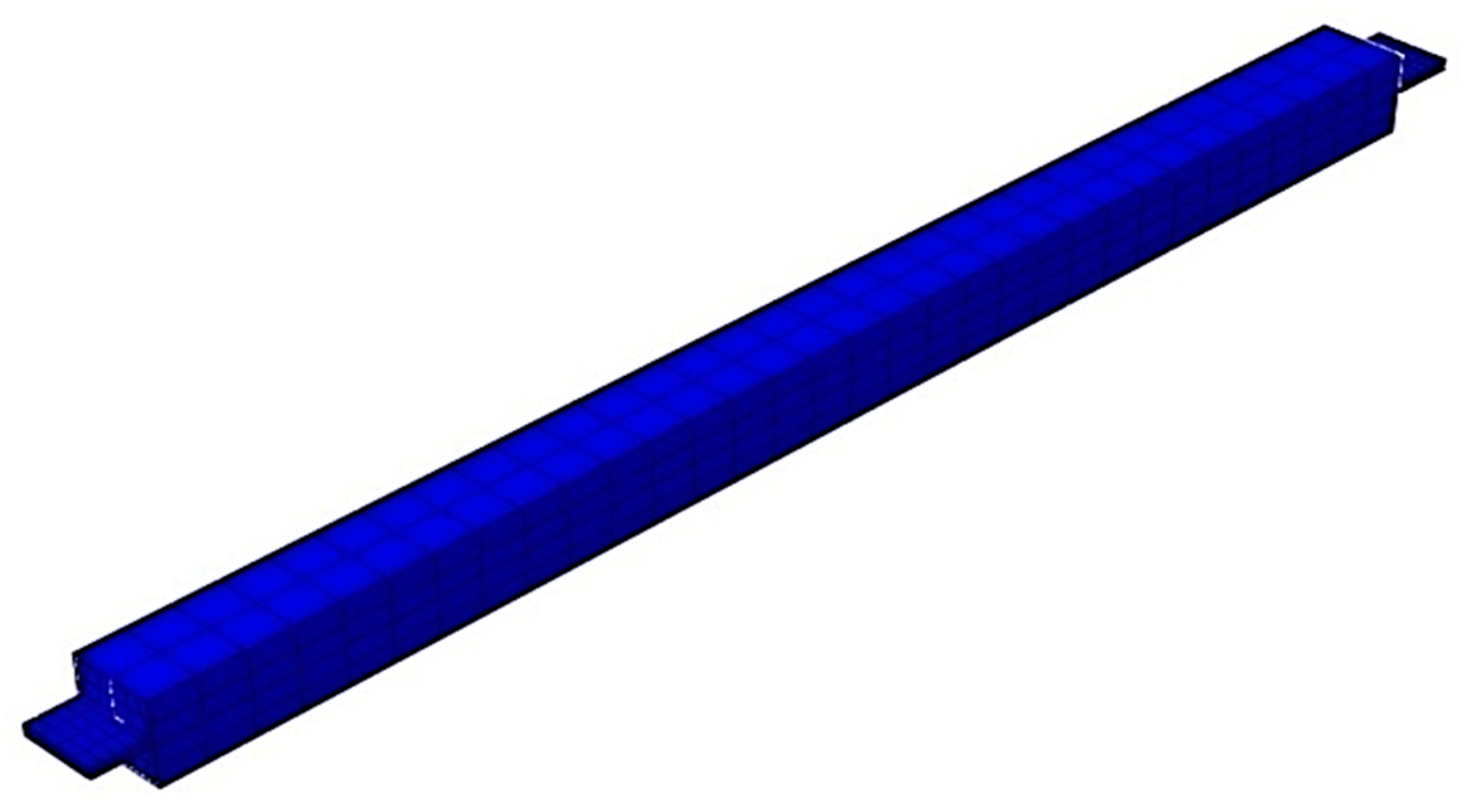
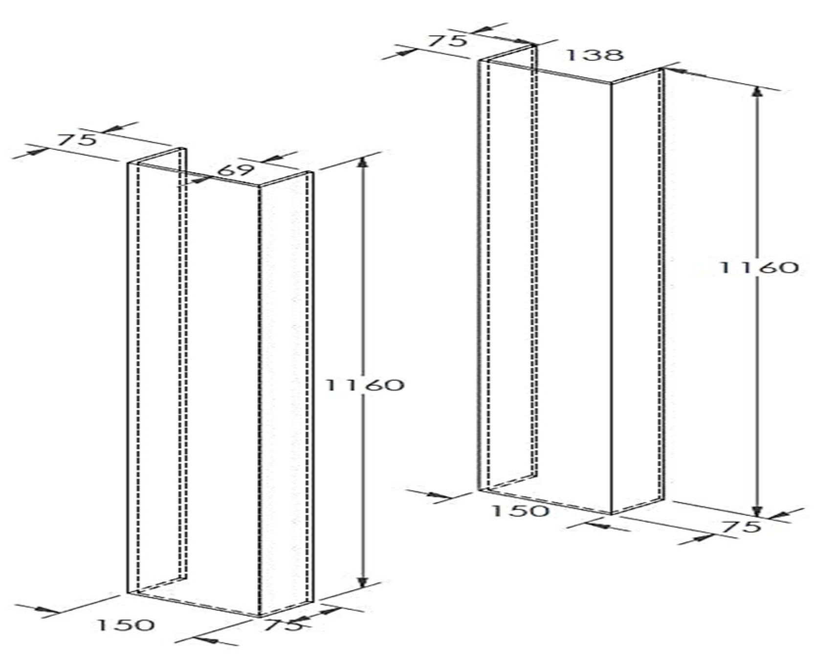
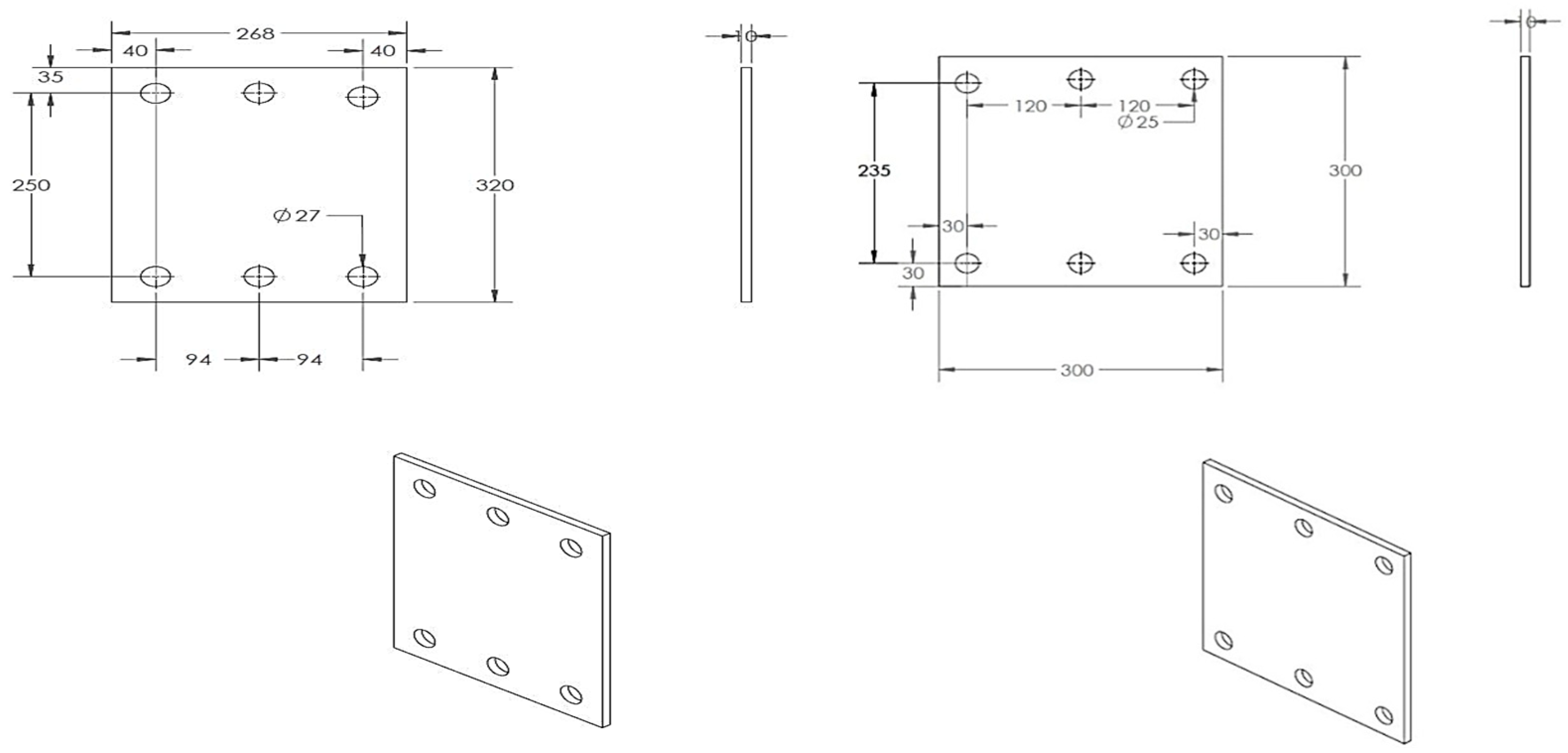
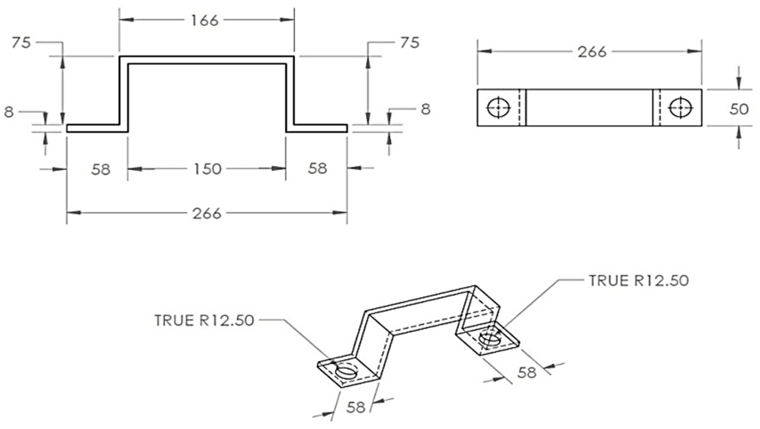
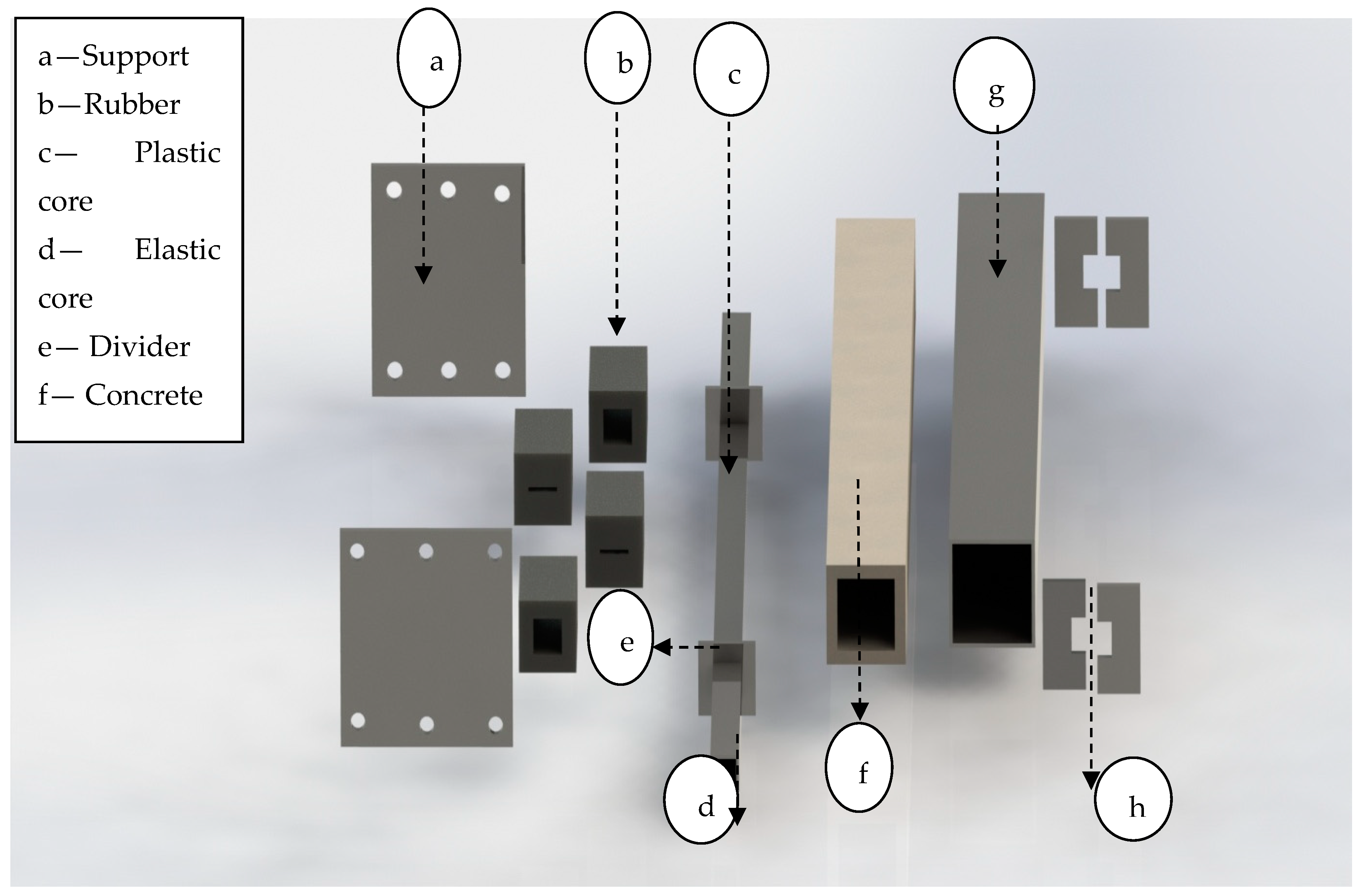
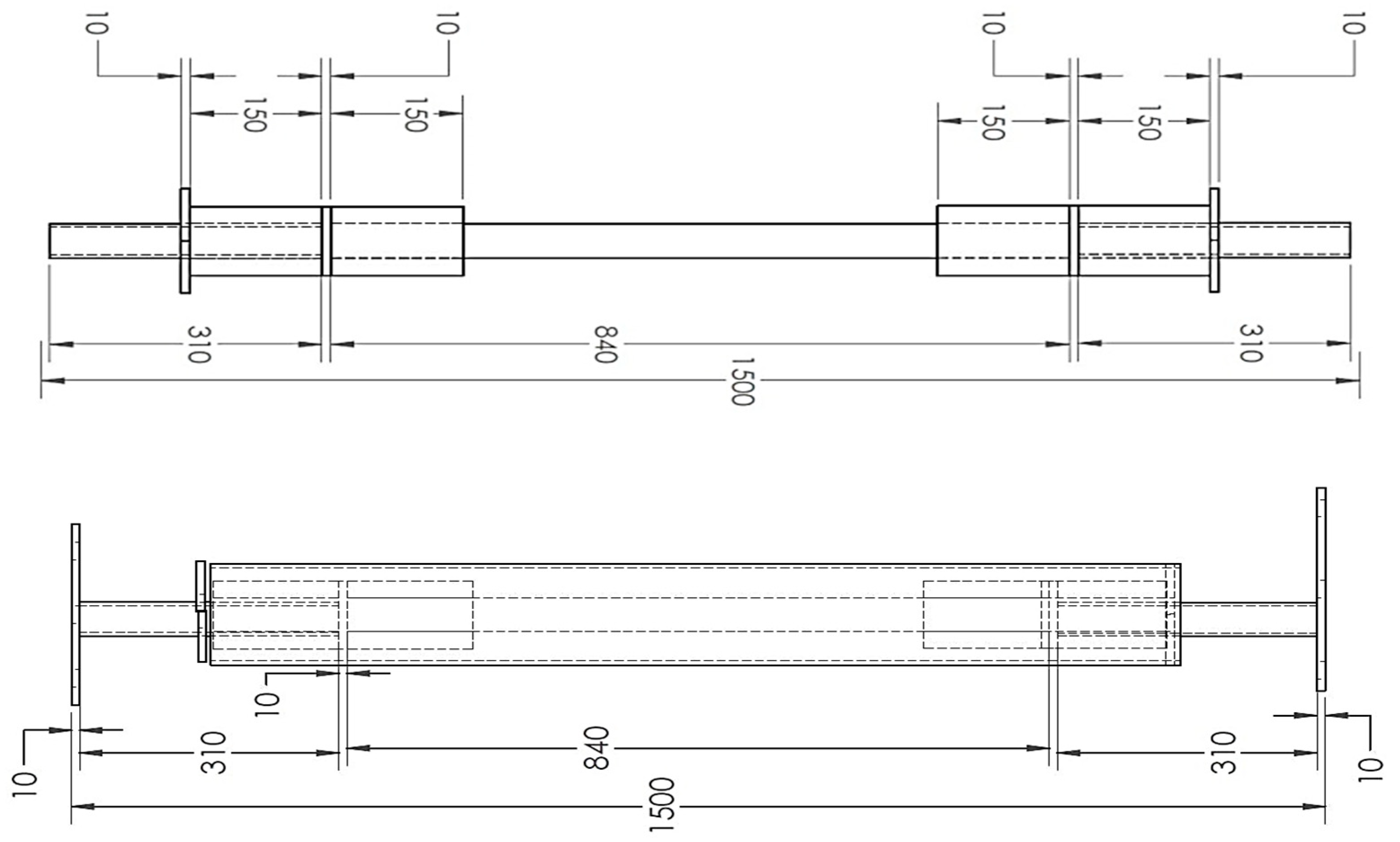
2.1. BRB Geometric Modeling

In order to perform the numerical simulation, the geometry of the BRB specimen was modeled based on the dimensions illustrated in Figure 2. Following the sketch, BRB different parts assembled together to form the final model, as illustrated in Figure 3.

2.2. Material Properties

Non-linear material property requires the use of the true stress (ơ) versus the plastic strain (Ɛpl) relationship; this must be determined from the engineering stress–strain relationship. Abaqus approximates the smooth stress–strain behavior of the material with a series of straight lines joining the given data points to simulate the actual material behavior. Any number of points can be used; therefore, it is possible to obtain a close approximation of the actual material behavior.

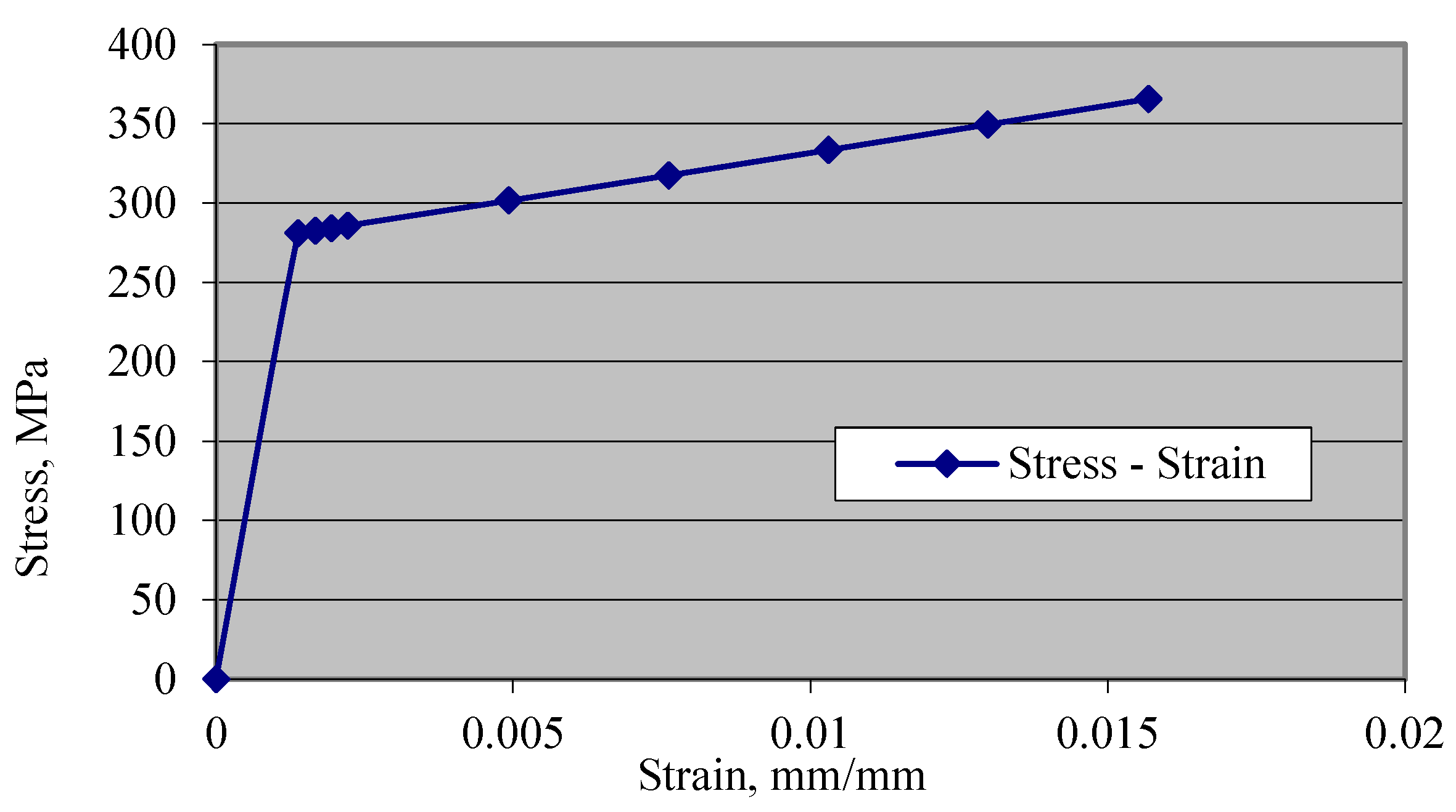
2.2.1. Steel Material Properties

The steel material properties were those of an elastic isotropic steel material with a density of 7800 kg/m3, an elastic modulus of 200 GPa and a Poisson’s ratio of 0.3. The yield stress value was 281 MPa, which reaches 365 MPa as ultimate strength. Steel strain–stress curves are shown in Figure 4 and Figure 5.

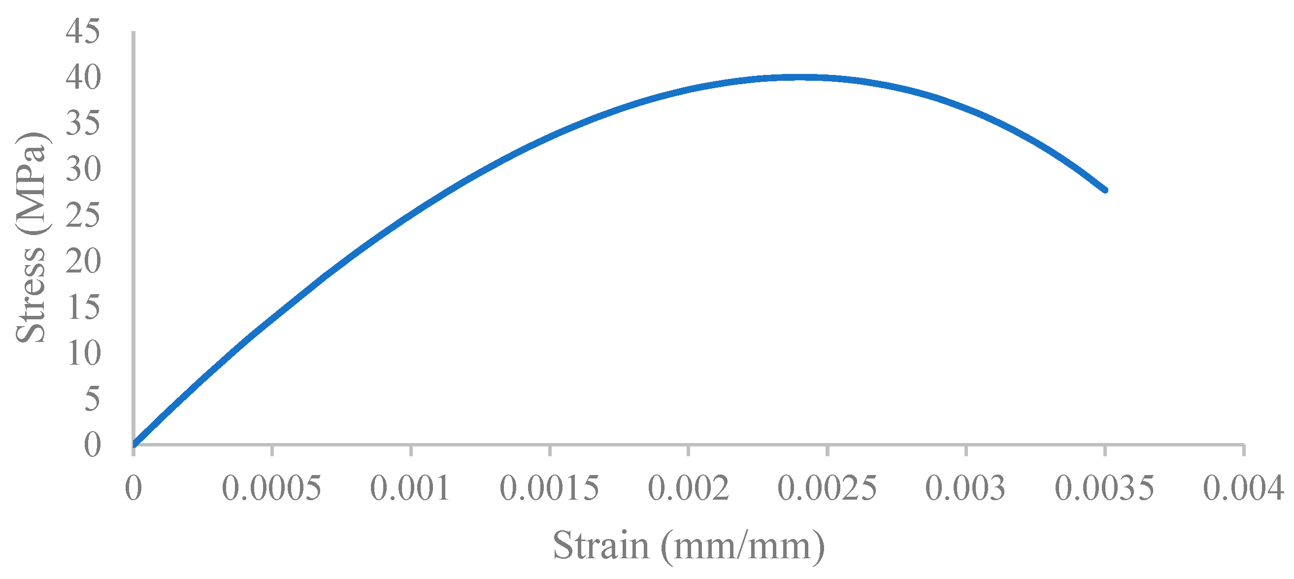
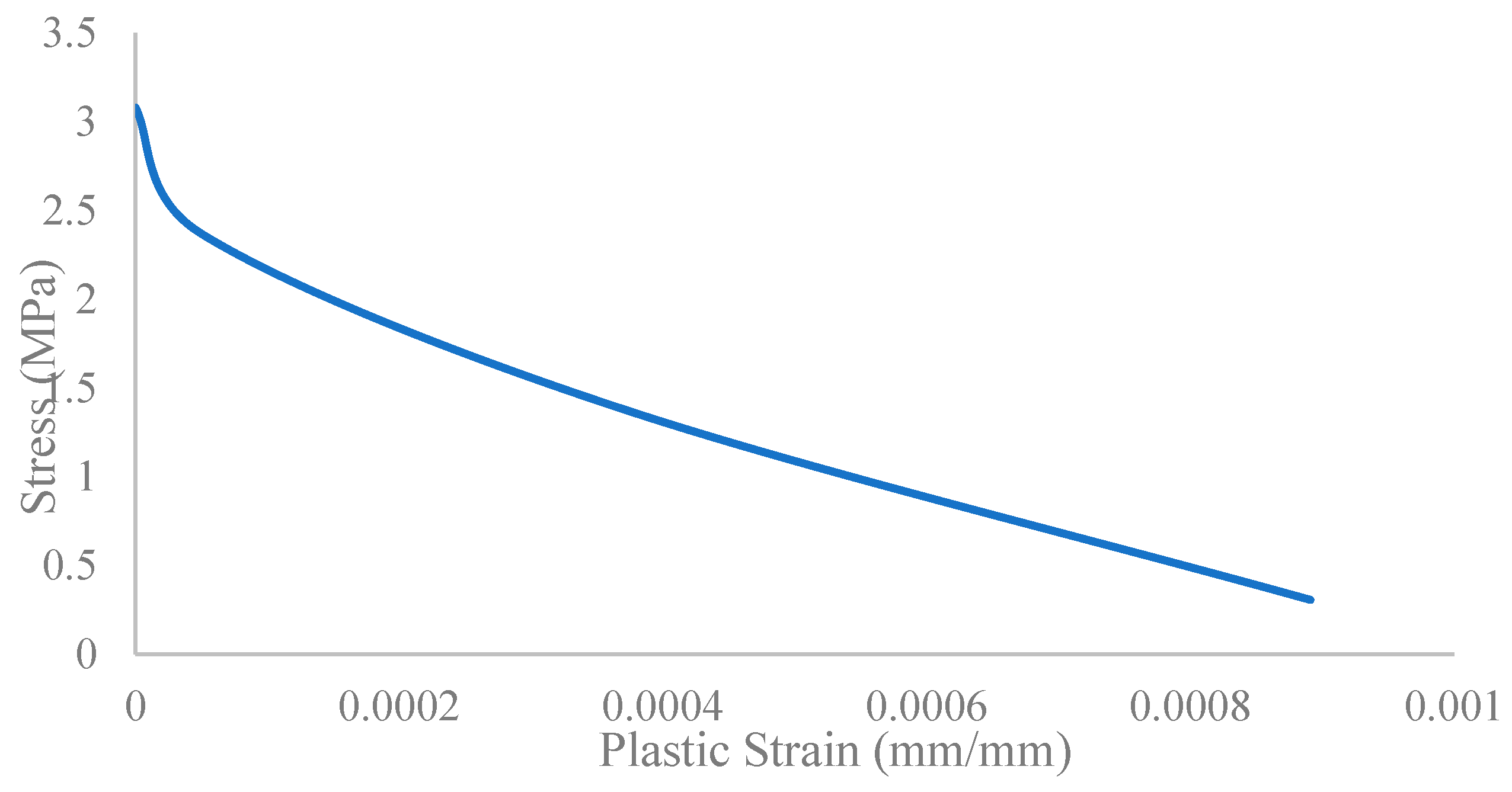
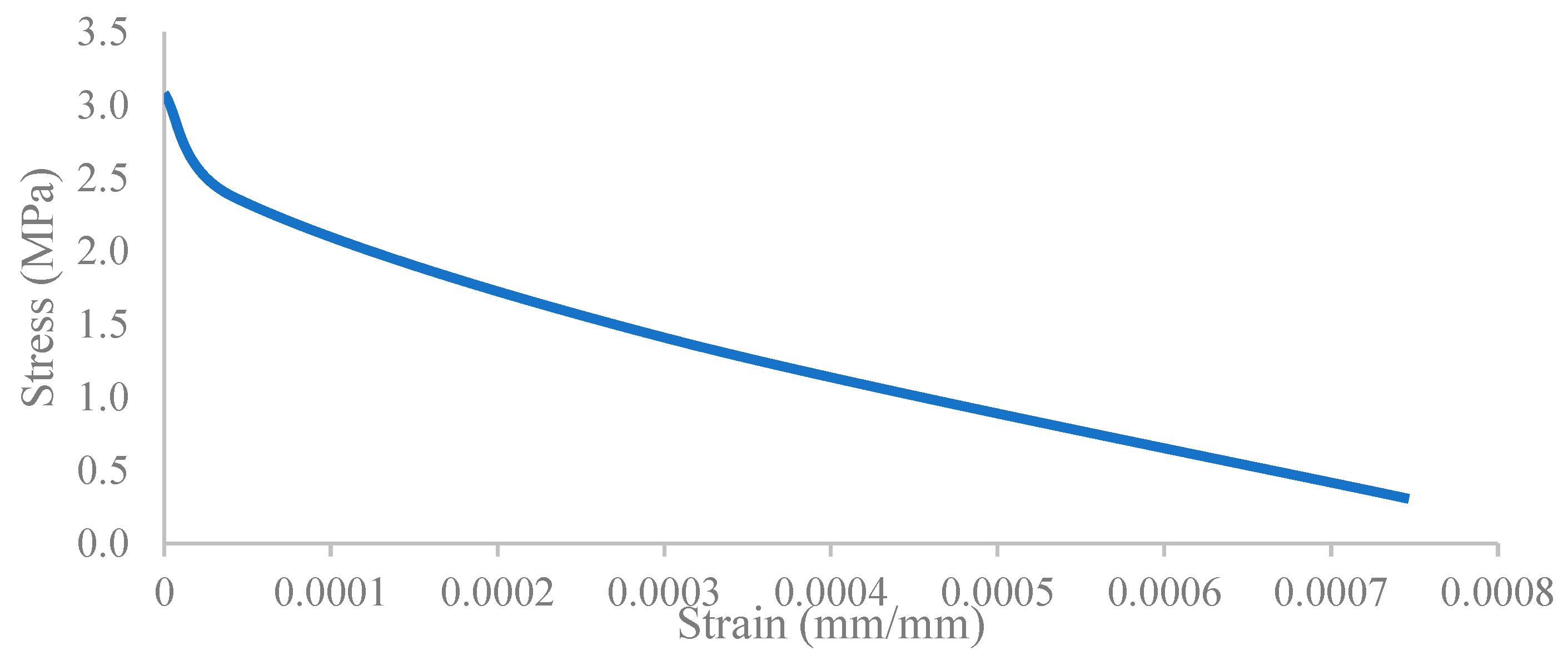
2.2.2. Concrete Material Properties

In this section, a comprehensive comparison between the behavior of the BRB infilled with conventional concrete and UHPFRC was conducted by investigating the material properties of both concrete types. The objective was to analyze and evaluate the differences in behavior and performance between these two materials when employed as infill material in a BRB device.
In addition to the compressive and tensile stress–strain behavior, many other parameters have been defined for material properties, including: dilation angle, eccentricity, fbo/fco, K and viscosity parameter, which are required to be used as material properties.
Two parameters of fbo/fco and K modify the yield surface. fbo/fco is the ratio of biaxial compressive strength to uniaxial compressive strength, which influences the yield surface in a plane stress state. The K parameter is used to define the shape of the failure surface in the deviatoric plane, which is the ratio between distances measured from the hydrostatic axis to tensile and compressive meridians.
The other two parameters are the dilation angle and eccentricity, which modify the non-associated potential flow. The dilation angle describes the angle of inclination of the failure surface towards the hydrostatic axis measured in the meridional plane. Eccentricity controls the deviation of the hyperbolic plastic potential from its asymptote.
The viscosity parameter is used for the visco-plastic regularization of the concrete constitutive equations.

Ultra-High-Performance Fiber-Reinforced Concrete

The UHPFRC premix, which is suitable to use for precast elements, was used as dry concrete in this research. UHPFRC does not have any coarse aggregates to reach compressive strengths beyond 150 MPa. Its unique blend of steel fibers and cementitious binders caused by low water content provide the extraordinary characteristics of high compressive flexural strengths, ductility and durability.
In this study, copper-coated micro straight steel fibers have been used as a composite material in UHPFEC at volume of 1.0%, the cooper steel fiber (C-GSF0325) has a tensile strength of more than 2500 MPa at diameter of 0.3 ± 0.05 mm and length of 25 ± 1 mm. Figure 6 shows the fiber material used in the UHPFRC matrix. Table 2 shows the UHPFRC mixture composition used in this study.
Compressive strength tests were conducted on cubes in accordance with BS EN 12,390 Part 3 (British Standards Institute, 2009 c). The curing period of 7, 14, 21 and 28 days was considered for the UHPFRC specimens to check their compressive strength. Figure 7 shows the compressive stress testing setup and result for cubes specimens. Results illustrate a ductile failure and concrete surfaces were observed to remain plain even at total strength loss. As observed in Figure 7, the compressive strength was higher compared to a grade-40 concrete; it reached maximum strength to 167 MPa in 28 days. The average strength of the samples in 28 days was 151 MPa. This comparison highlights the potential superiority of UHPFRC in terms of strength performance compared to conventional concrete in this study.
In this section, compression and tensile stress–strain constitutive models for UHPFRC in numerical study are presented. Figure 8 indicates the stress–strain curve for compression and Figure 9 for tension. Table 3 provides the corresponding parameters for concrete damage plasticity.

Conventional Concrete

In this research, conventional concrete, which is known as G40, was used to highlight the differences in BRB performance compared to UHPFRC concrete. For concrete, plasticity damage was included in the modeling. The concrete damage plasticity model is an isotropic model derived from the Drucker–Prager yield criterion. It requires linear elasticity for the first part of the stress–strain relationship. That can be assigned by providing the Young’s modulus and Poisson’s ratio. It combines two failure mechanisms, one for tension (cracking) and one for compression (crushing). The plastic strains upon yielding can be determined by providing tabular stress vs. strain points, derived from uniaxial testing (compression and tension) performed on the concrete. The stress–strain constitutive curves for conventional concrete are presented in Figure 10, Figure 11, Figure 12 and Figure 13. The numerical values for conventional concrete damage plasticity and its composition mixture are shown in Table 4 and Table 5.

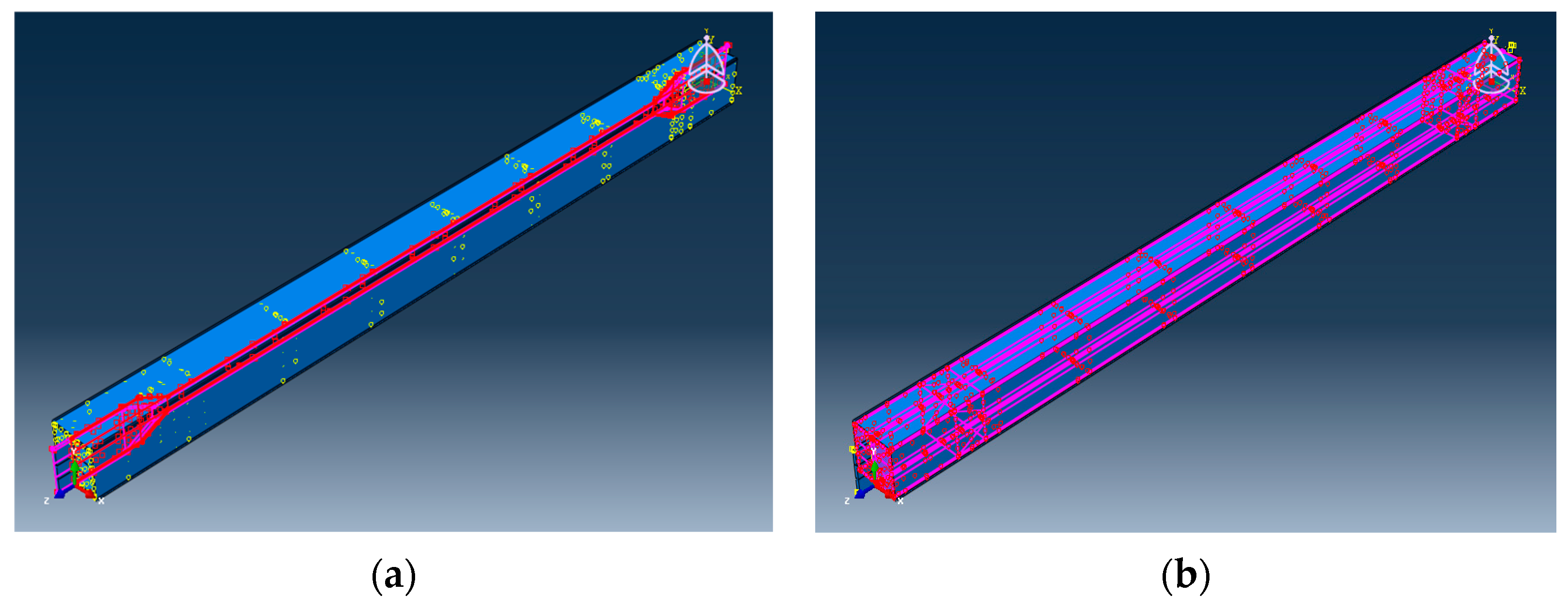
2.3. BRB Meshing Model

The Steel core was modeled using an 8-node linear brick (C3D8R). The concrete component and steel tube restrainer were modeled with the same elements. In this simulation, node compatibility was confirmed by using the correct mesh topology as all the elements were meshed with a similar element size to verify that two contacting parts shared the common nodes. Therefore, all the elements in the model, including the steel core, concrete, and steel tube restrainer, were meshed by using 75 mm size based on mesh and time dependency sensitivity analysis. Figure 14 shows meshing of the components of the BRB device.

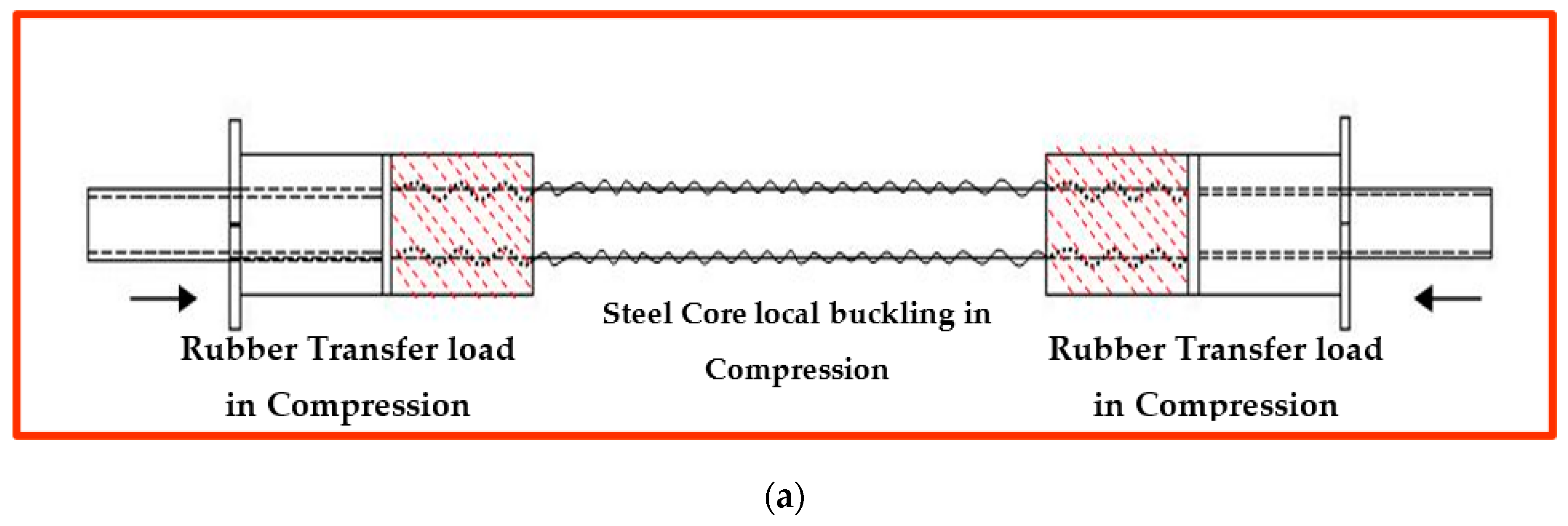
2.4. BRB Contact Modeling

The contact tool was used to define the interaction between the steel and concrete elements. The embedded region, tie constraint and surface-to-surface interaction of contact areas were used between the element’s surfaces. The embedded region constraint was employed between the steel core and concrete, while surface-to-surface interaction was applied between the steel restrainer tube and concrete, as shown in Figure 15. Additionally, it is worth mentioning that a friction coefficient of 0.1 was utilized in the analysis based on previous studies conducted by Stiller (2021) [30].

2.5. BRB Boundary Condition and Location

BRB support was set to rigidly fix at one end in order to restrain its movement in all degrees of freedom. Furthermore, displacement control was applied to the specimen at the other side of the head segment. Displacement was applied as push and pull loads on the model, as shown in Figure 16. The maximum displacement of 100 mm was broken into a number of sub-steps to simulate the incremental load applied in the cycling test. In order to ensure the achievement of the optimum load increment, automatic time stepping was activated when the nonlinear behavior occurred.

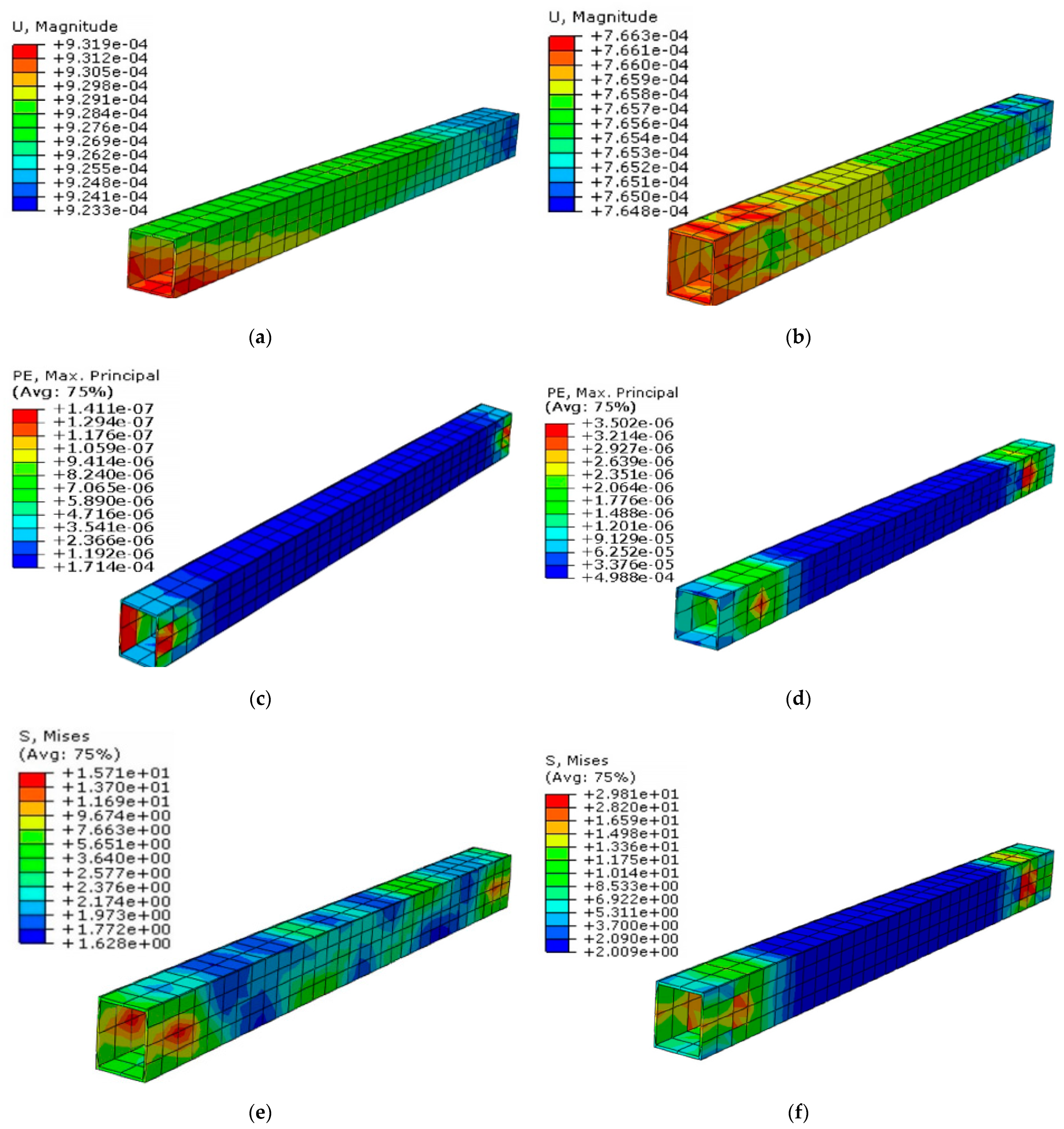
3. Finite Element Analysis Results for UHPFRC and Conventional Concrete Filler

As mentioned previously, cyclic analysis was conducted to investigate the behavior of the BRB model under applied amplitude. There was a small gap between the core and the filler material to provide sufficient space for the core to buckle. This localized buckling phenomenon facilitates the dissipation of energy during compression loading. The observed deformation pattern is a result of core local buckling. As BRB undergoes cycles of tension and compression, the locations of these local buckling occurrences may change or shift within the core element. This dynamic behavior contributes to the overall energy absorption and dissipation capability of the BRB system. Consequently, it effectively mitigates the detrimental effects of cyclic loading and enhances the structural performance of the system under seismic conditions. Based on the numerical results, the maximum deformation in the BRB was observed due to buckling occurring in the middle of the plastic core, as shown in Figure 17.
The maximum deformation of the core in the BRB model filled with ultra-high-performance fiber reinforced concrete (UHPFRC) is lower than that of the G40 model. This is attributed to the higher strength properties of UHPFRC, which enhance the confinement of the core and consequently reduce the local buckling. The reduced curvature observed in the shape of core buckling in UHPFRC BRB does not indicate imperfect performance; instead, it demonstrates the effectiveness of UHPFRC in restraining the core against significant buckling.
Similarly, core strain follows the deformation pattern and exhibits lower values in BRB with UHPFRC filler. The increased strength of the UHPFRC material also enhances the resistance force of the BRB against compressive loads, leading to an increase in the maximum stress experienced by the core (Table 6).
As it can be seen in Figure 18, core local buckling and its deformation have a direct effect on concrete filler. Consequently, UHPFRC exhibits less deformation compared to conventional concrete due to its advanced material properties, allowing the steel core to buckle without causing significant damage to concrete. However, the high brittleness of conventional concrete results in inadequate restraint for the steel core, especially under higher applied loads, which can lead to concrete damage and global buckling of the BRB. Furthermore, it is worth mentioning that the strain in conventional concrete is greater than that of UHPFRC due to increased pressure from the core element on the concrete surface, whereas stress in UHPFRC is higher due to its superior resistance to applied loads (Table 7).
Concrete filler is restrained by an additional layer of buckling protection known as the steel tube restrainer. Any deformation or buckling that occurs in the concrete filler also affects the steel tube restrainer. As depicted in Figure 19, the effective confinement of the concrete results in negligible load transfer to the restrainers in both models. However, the steel tube restrainer exhibits a similar pattern to the concrete filler, indicating lower displacement and strain, but higher stress in UHPFRC filler compared to conventional concrete. (Table 8)

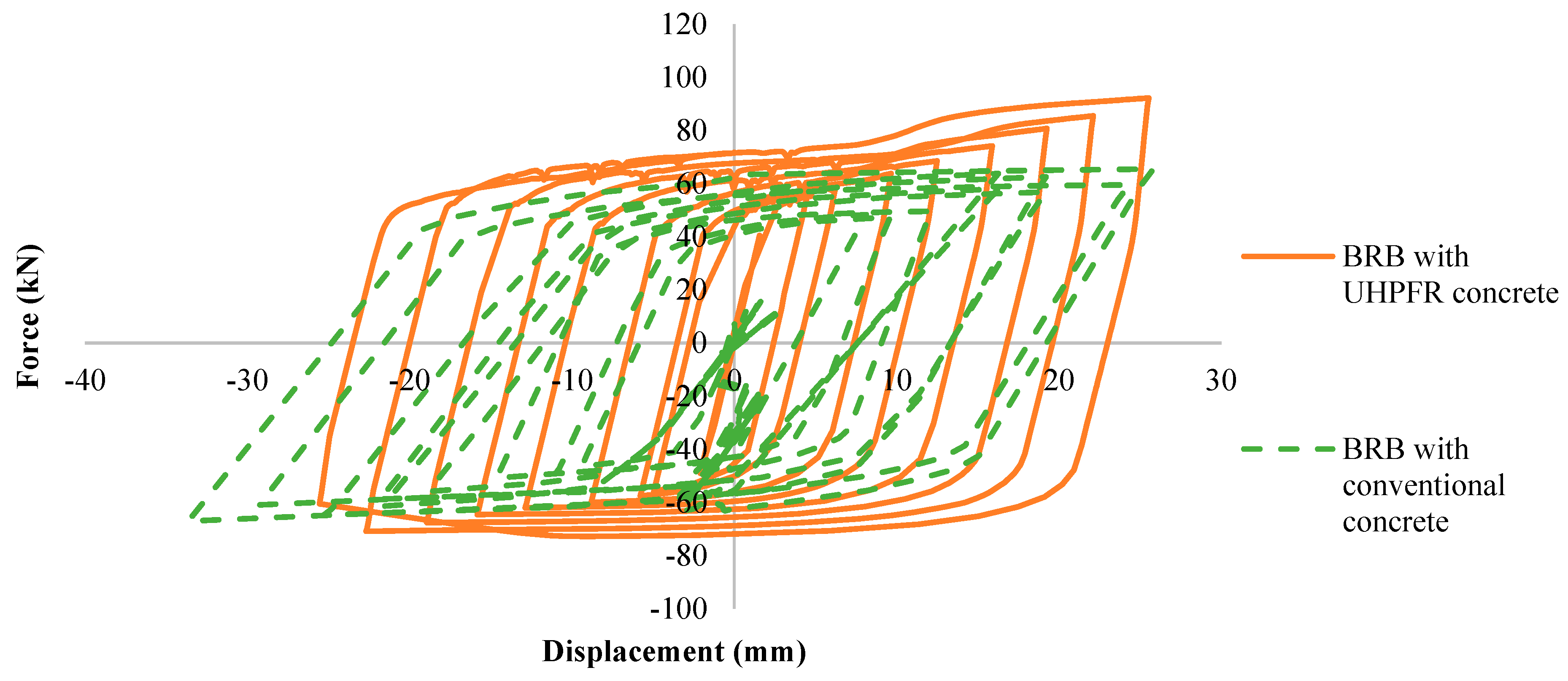
3.1. BRB Hysteretic Response Result for UHPFRC and Conventional Concrete Filler

A cyclic test was conducted to investigate the behavior of the BRB model filled with conventional concrete and UHPFRC concrete under applied displacement amplitudes, which is indicated in Figure 1. The maximum resistance force was calculated on one node at the applied load side of both BRB models along the horizontal direction. The outline of the hysteresis curve was observed to be smooth and responded elastically.
As is illustrated in Table 9, the maximum displacement and force values in the BRB filled with conventional concrete and UHPFRC under tension are nearly identical. This observation suggests that changes in filler material do not have a significant effect on the tensional performance of BRB. In contrast, in compression, resistance force in BRB filled with UHPFRC was observed to increase compared to the model filled by conventional concrete. This increase in resistance force is attributed to the superior confinement capability of UHPFRC. Consequently, the maximum stress experienced by the core element of BRB filled with UHPFRC was increased by approximately 28%.
As can be seen in Figure 20, based on the material properties of G40 concrete, the core is more prone to have local buckling, which results in more displacement. However, UHPFRC exhibits advanced behavior, providing improved restraint to the core element in BRB. This enhanced restraining ability of UHPFRC reduces the risk of global buckling in BRB, thereby contributing to its improved overall performance and stability.
Previous experimental studies conducted by Esfandiari (2023) confirmed that using steel fibers in conventional concrete enhances the load capacity of the BRB system up to 25% [27]. Additionally, Ghaeidi et al. (2011) proved that using concrete with a compressive strength exceeding 30 MPa provides sufficient confinement for the core and improves the performance of BRBs [31]. These findings highlighted the advantages of using UHPFRC as a filler material in the BRB device. These advantages include increased confinement of the steel core, higher resistance forces, reduced occurrence of local buckling, and overall enhanced performance and behavior of BRB under compression loads.

3.2. Concrete Compressive Strength Effect on BRB Performance

Since the main focus of this study is on BRB’s filler material, a parametric study was conducted to investigate the effects of different concrete filler materials on the performance of a buckling-restrained brace (BRB). For this purpose, three types of concretes, including low-grade concrete with compressive strength of 25 MPa, medium-grade concrete with 50 MPa strength and high-grade concrete with 90 MPa compressive strength were considered to implement as filler material for the BRB device.
As is illustrated in Figure 21, the results for the various concrete fillers regarding their effect on BRB performance indicate that filler material does not exhibit a noticeable effect on the BRB performance during tensional movement. However, as shown in Table 10, in compression, the expected trend of increased concrete compressive strength leading to higher resistant force in the BRB during applied cyclic movement is observed. By changing the concrete filler material from low grade to medium grade, the maximum resistance force increased by 15%. Similarly, replacing low-grade concrete with high-grade concrete leads to a 23% enhancement in the maximum compression resistance force. As was mentioned previously, this increase in resistant force is attributed to the improved confinement capability of the concrete with higher compressive strength.
Hence, the result of the parametric study revealed that the effect of concrete compressive strength of more than 50 MPa on BRB performance is negligible and it may not justify using concrete with very high compressive strengths due to its associated costs.

4. Experimental Test of BRB with UHPFRC Concrete

The main objective of the experiment test was to assess the actual performance of the BRB with UHPFRC concrete filler and validate the result obtained from finite element analysis. For this purpose, a prototype of BRB with UHPFRC concrete was constructed according to the same specifications and details used in finite element simulation.

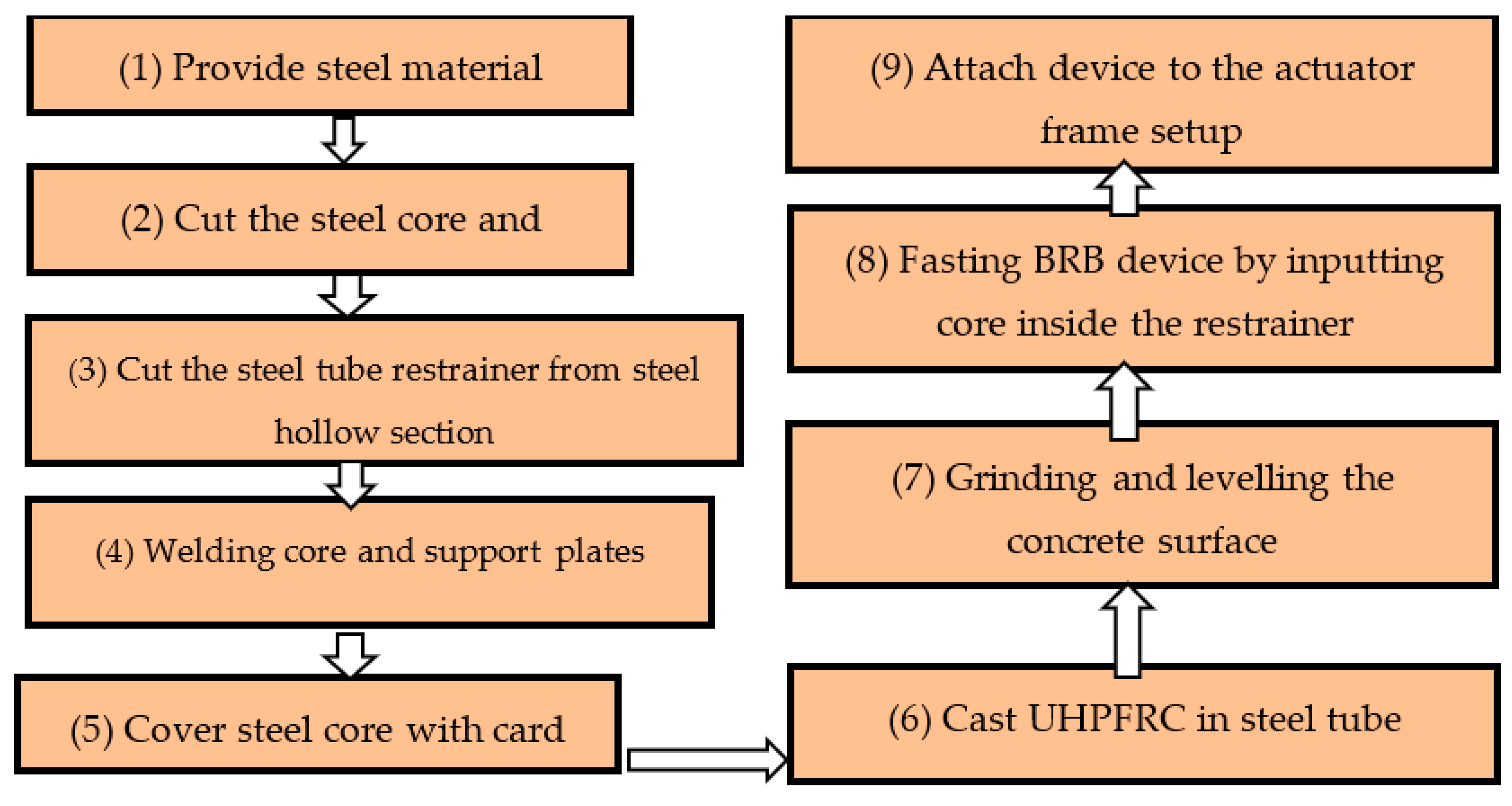
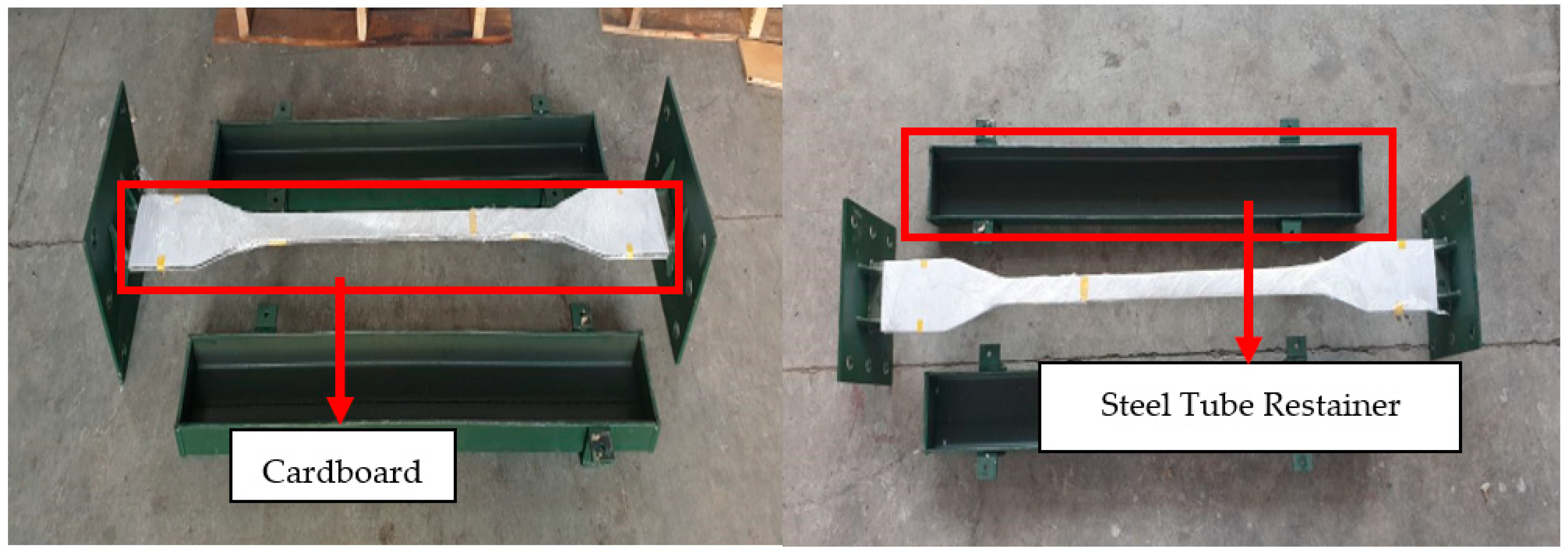
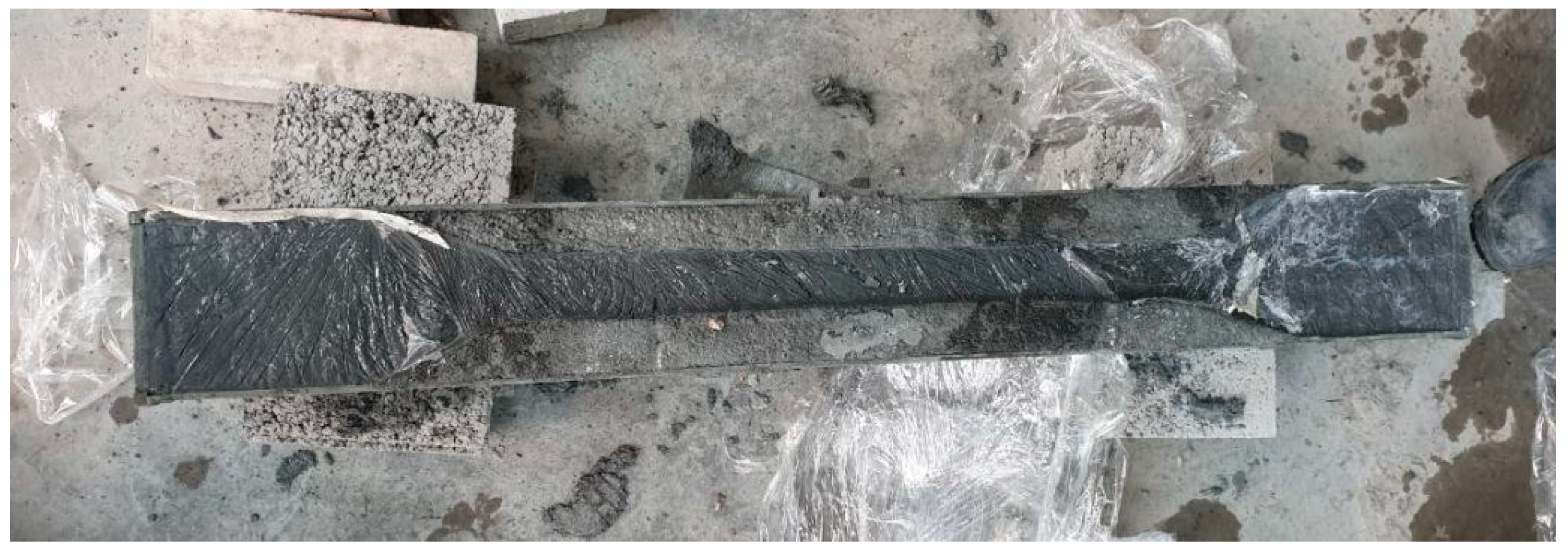
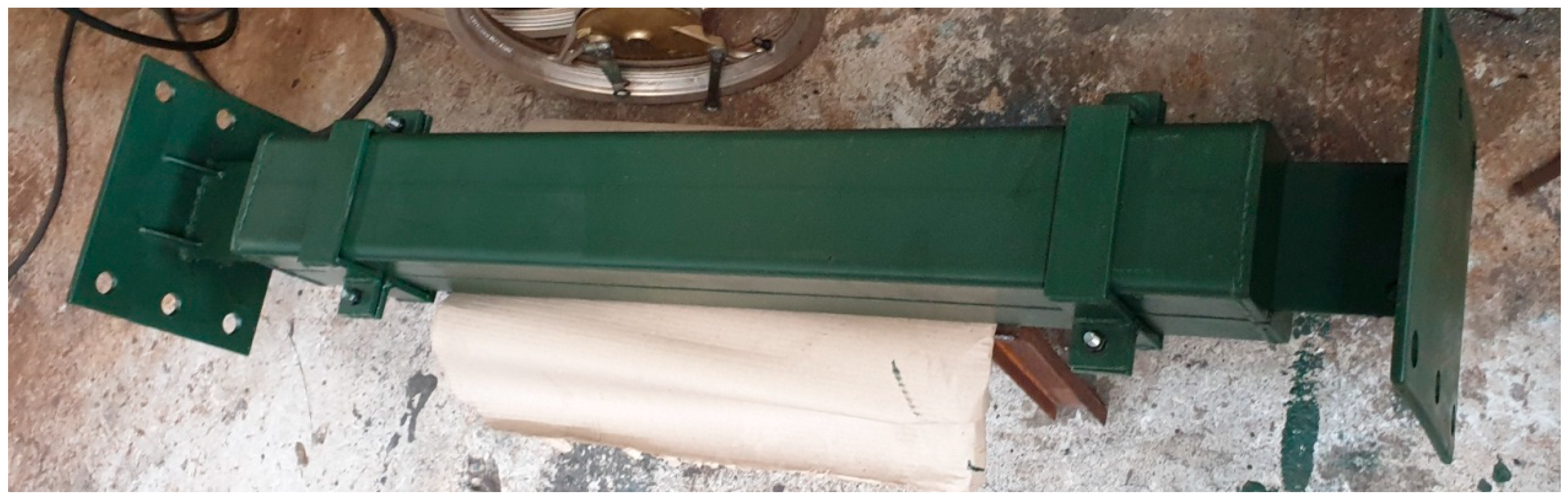
4.1. BRB Fabrication Procedure

The fabrication of the BRB prototype involved nine steps, as shown in Figure 22: (1) providing steel material such as steel plates and hollow sections, (2) cutting the steel core to the assumed dimensions and preparing supports for the steel core, (3) creating a steel tube restrainer from the steel hollow section, (4) welding the core element to support plates, (5) covering the steel core with cardboard, (6) casting UHPFRC inside half of the steel tube restrainer, (7) after a curing period of 28 days for concrete, grinding and leveling the surface of UHPFRC to achieve a smooth and even finish, (8) assembling the BRB device by inserting the core element into the steel tube restrainers and (9) assembling and attaching the BRB device to the dynamic actuator setup frame.
To fabricate the BRB prototype, steel materials were cut and assembled based on the dimensions provided in Table 1. The length ratio of the plastic core was set to 0.44 (840 mm), as is indicated in Figure 2 [29].
The main body of BRB consists of a steel tube restrainer with a thickness of 6 mm, a cross section of 150 × 150 mm, and a length of 1160 mm, as shown in Figure 23. The steel tube was cut into two halves to facilitate the casting of concrete inside each half section and allow for inspection of the core condition after conducting the experimental test.
Figure 24 illustrates the support heads that were designed for both ends of the core. These support heads were fabricated by creating bolt holes according to the sizes specified for the support and actuator head. The design allows the prototype to be securely fixed to the experimental setup.
In addition, two steel belts were employed, as is indicated in Figure 25 to enhance the strength of the device during the test. These belts were used to restrain the BRB and prevent any out-of-plane movement.
The experimental test was conducted using a Shimadzu dynamic actuator with a 300 kN load capacity at UPM structural laboratory. As shown in Figure 26, the steel core segment was covered with a 2 mm-thick cardboard to create a predetermined gap between the steel core and concrete. This gap allows the smooth sliding of the steel core inside the concrete during the test.
The UHPFRC concrete was used as the filler material for BRB. The casting process began by pouring the concrete into one of the half sections of steel tube restrainer. Subsequently, the steel core, covered by cardboard, was positioned inside the wet concrete to create the determined gap for the core. The same procedure was repeated for the other half section to ensure uniformity in the casting process. Figure 27 shows the cast concrete before grinding and leveling of the surface. To allow the UHPFRC concrete to reach its maximum strength, the cast concrete was covered with a plastic sheet and cured for 28 days.
After 28 days, the concrete surface was ground and leveled in preparation for inserting the core, as indicated in Figure 28. A grinder machine was utilized to achieve a smooth concrete surface, allowing the steel core to move sufficiently inside concrete during the test.
By completing the concrete surface grinding and leveling, the steel core was placed inside the steel tube restrainer, and both half sections were positioned on top of each other to assess the efficiency of the assembly and steel core movement, as shown in Figure 29.
After conducting the smooth core movement testing, the prototype was disassembled and transferred to the testing actuator frame setup. For this purpose, one half side of the steel restrainer and steel core was installed in the frame testing setup by bolting the support heads of the steel core to the support to create fix joints. The other end was connected to the dynamic actuator head connector to transfer the movement of the actuator to the steel core (Figure 30).
Afterward, strain gauges were attached to the surface of the steel core and concrete. They were attached in the middle and at both ends to measure the strains of these elements during the test. The location of the strain gauges is shown in Figure 31 and Figure 32.
Following the attachment of strain gauges, the prototype was assembled by positioning both half sides of the steel tube restrainer and securing them with two steel belts. To avoid and restrict any out-of-plan movement during compression, an additional belt was implemented in the middle of the BRB device. Then, the BRB prototype was aligned with support and actuator head in a horizontal line as shown in Figure 33 to complete the BRB assembly in the testing setup frame.
Absolute linear displacement at BRB prototype during the testing procedure was measured using linear voltage displacement transducers (LVDTs) which were connected to a data logger (model: UCAM 60 Kyowa) to record the data. The displacement of BRB was measured and monitored by positioning two LVDTs on both sides of the actuator head connector, as shown in Figure 34. The outer LVDT recorded the compression displacement, while the inner one recorded the tension displacement during the testing.

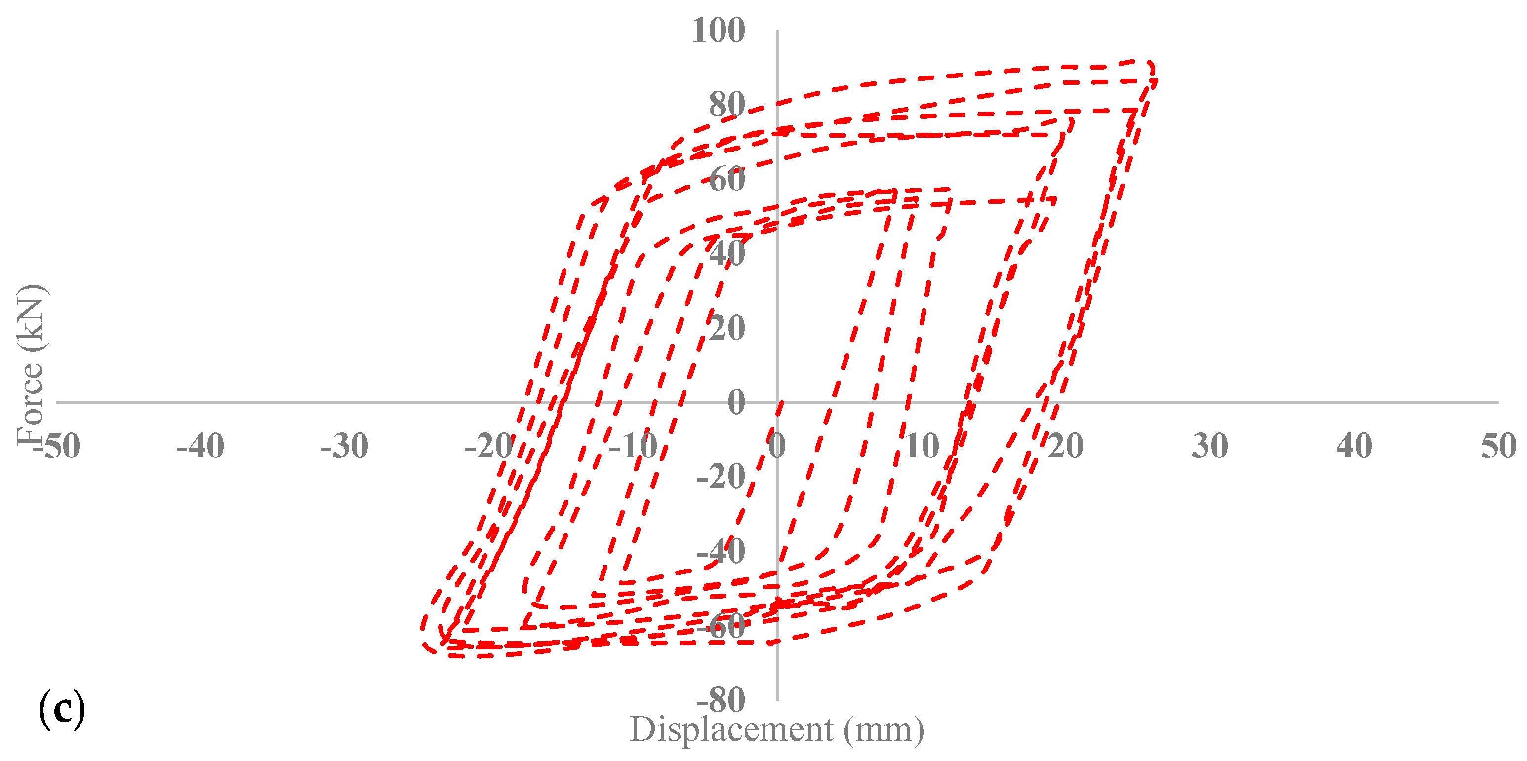
4.2. BRB Experimental Testing Results

The results of the experimental testing were analyzed based on the selected amplitude, as explained in the previous section. The failure stage of BRB began when the maximum strength reached the strain hardening regime. The localization of this failure was observed at its weakest point, which combined multiple instances of local buckling in the core. This led to a significant frequent yielding and eventually resulted in failure through the cutting of the steel core due to excessive loading.
Figure 35 indicates the occurrence of complete local buckling during the BRB testing. Figure 36 illustrates the failure stage of the core, which happened at its weakest point due to it reaching its maximum strength capacity.
The obtained force–displacement relation Hysteresis curve for conventional BRB is shown in Figure 37. The graph illustrates that the maximum force capacity of BRB reached up to 92 kN with 26 mm deformation in tension and 72.5 kN with 26 mm in compression. Furthermore, the backbone curve was plotted and the polynomial formulations were extracted and are presented in Figure 38.

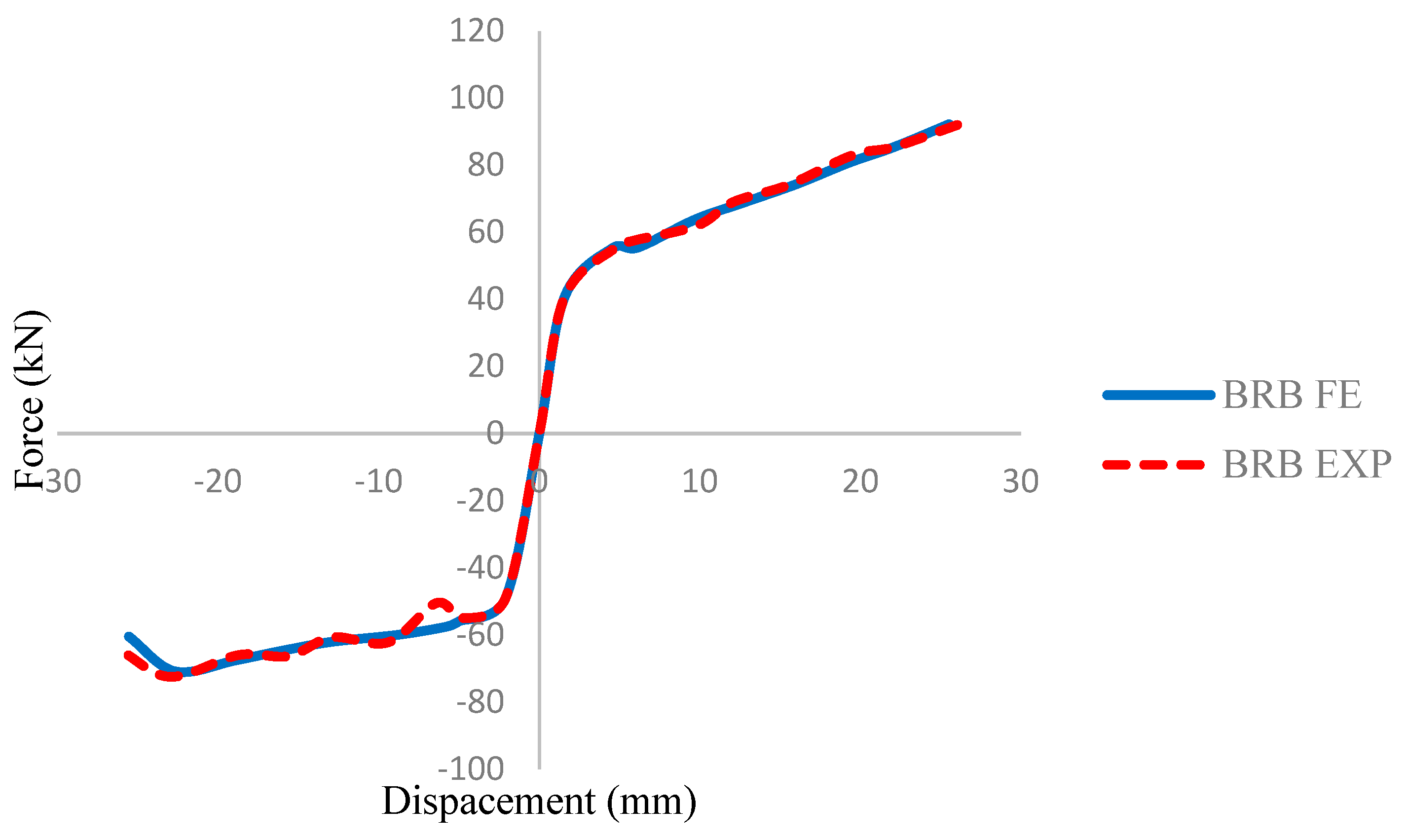
5. Validation of Experimental and FEA Result for BRB

In this section, the validity of the research is established through comparison of the experimental and the numerical simulation results. The results of the experimental cyclic test show sufficient agreement with the values obtained from the numerical analysis. This is evident from the similarity observed in the force and displacement profiles between the experimental and the numerical tests. However, as the pinching effect occurs, a difference was detected between experimental and numerical results. This divergence is caused by the fact that, in the experimental setup, the fixes used in the test setup are not ideal constraints and at very low displacement values, even very small backlash is not negligible [32].
The cyclic results reveal a maximum error of 4% in the resistance forces between the experimental and numerical data for BRB, as indicated in Table 11 and Figure 39. Additionally, Figure 40 illustrates the full backbone curve, which further supports the accuracy and reliability of the numerical simulation by comparing the complete behavior of the BRB.

6. Proposed Design of Rubber Buckling Restrained Brace (RBRB)

As previously discussed, the functionality of the BRB device relies on the steel core’s ability to withstand tension and compression forces, which is enhanced by adding the UHPFRC concrete as the filler instead of conventional concrete. However, it is important to note that the BRB device becomes totally out of function once the steel core has fully yielded in tension. After this stage, the device does not perform anymore, which can potentially cause structural collapse during severe vibrations.
Therefore, in this study, an attempt was made to address this drawback by proposing a new design for conventional BRB. This design involves the implementation of a high damping rubber component between the steel core and UHPFRC concrete, serving as an additional system to resist against applied vibration and provide integrity to the device during excessive deformation.
As is shown in Figure 41, the proposed rubber buckling restrained brace (RBRB) consists of several components: a steel core separated into elastic (c) and plastic sections (d), dividers (e) which were situated through the core element; UHPFRC material (f) as the filler and hyper-elastic rubber (b) component which is inserted in the created gap between steel dividers and concrete, two steel support heads (a), and one steel tube restrainer (g) with two steel caps (h).
Figure 42 shows the design process details of RBRB. The core element is made up of elastic and plastic sections, where the plastic section has the main role in load bearing, while the elastic sections were designed to provide more resistance, simulating the elastic section in a conventional BRB. Steel dividers are steel plates placed through the core element and welded with the elastic and plastic sections on both sides. The steel tube restrainer is a hollow section which has the ability to restrain the whole device as the main body to avoid global buckling. The core element is inserted inside the concrete, ensuring a predetermined gap for the placement of the rubber components, followed by covering the concrete component with the steel tube restrainer.
As is shown in Figure 43, during tension, the force transfers from the end joints to the core, which absorbs the load through elongation and causes reduction in cross-sectional area. Meanwhile, this applied load is transmitted to the dividers, which push the outer rubber components and compress them against the concrete. The hyperelastic behavior of rubber provides excessive resistance to the tensile strength of the core.
In compression loading, the force transfers from the end joints to the core and dissipates through local buckling, similar to BRB behavior. Similar to tension, rubber components are compressed between the steel divider and concrete and generate additional strength to the device.

6.1. Investigation of RBRB by Performing FE Simulation

Similar to BRB modeling, numerical studies were conducted for the RBRB device. Table 12 presents the details and specifications of the RBRB model. It consists of a 300 mm2 core cross-sectional area with a total length of 1500 mm. The dimensions for RBRB and the generated model can be seen in Figure 44.

6.1.1. RBRB Material Properties

The UHPFRC concrete and steel material used to accurately model RBRB are similar to those of the BRB material properties. Rubber material behavior in RBRB has been modelled as hyperelastic, based on material properties provided by Hercules® Engineering (SEA) Sdn Bhd, as shown in Table 13 and Table 14.

6.1.2. RBRB Meshing Model

Steel core and concrete were modeled using the same elements for the BRB meshing sizes. The rubber component mesh size was set to 10 mm. Figure 45 shows the RBRB meshed elements based on the aforesaid information.

6.1.3. RBRB Contact Modeling

The contact tool was used to define the interaction between the steel and concrete elements, the same as in BRB. The embedded region constraint was implemented to facilitate the interaction between rubber, steel core and concrete, as shown in Figure 46.

6.1.4. RBRB Boundary Condition and Loading

The RBRB boundary condition model for supports, head segments and applied displacement was defined identical to BRB modeling.

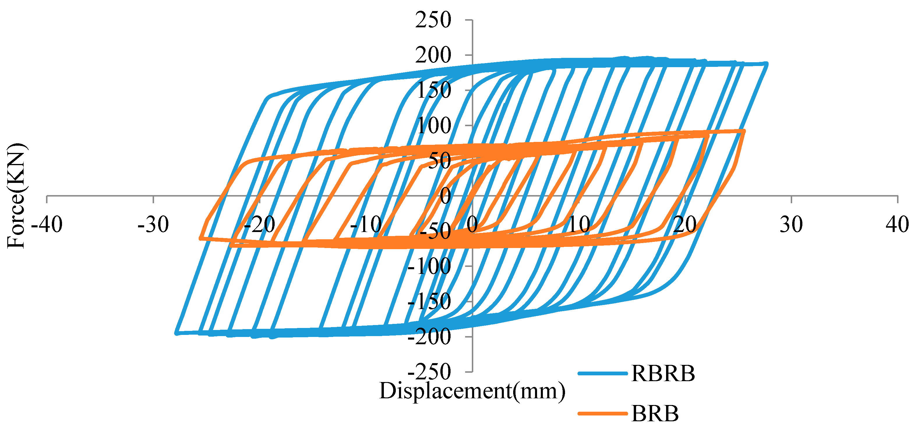
7. BRB and RBRB Numerical Analysis Results Comparison

Figure 47 demonstrates the enhanced performance of RBRB due to the additional resistance force provided by the rubber components. As can be seen in Table 15, the implementation of the rubber components in the RBRB significantly improved its loading capacity. The RBRB achieved a maximum resistance force of 198.72 kN at a displacement of 20.7 mm, representing a 110% increase compared to a conventional BRB.

BRB and RBRB Performance Comparison

In this section, the effective damping (Keffb), effective stiffness (φ) and dissipated energy (W) for both specimens were calculated. The energy dissipated in a single hysteresis loop (Wi) is calculated by considering the area enclosed by the hysteresis loop using Equation (1) Figure 48. Fl(u) and Ful(u) are forces at displacement ‘u’ throughout the loading and un-loading process. The summation of the total area enclosed by the hysteresis loop gives the cumulative energy dissipated in the specimen. The performance of BRB and RBRB subjected to cyclic loads is shown in Figure 47. As it can be seen in Table 16, both devices are capable of dissipating the energy, which was 8021 kN.mm for BRB and 11.806 kNmm for RBRB, which indicates an increase of 47.19%. The damping ratio was also calculated as 51 percent for BRB and 53 percent for RBRB as calculated based on BS EN 15,129:2009 in Equation (2). Additionally, the effective stiffness of both devices has been investigated, and was 12.76 kN/mm for BRB and 27.2 kN/mm for RBRB based on Equation (3), where VEbd is the force corresponding to dbd, obtained at the third load cycle.
Δ W i = v min v max ( F i u F ul u )
φ = W (dbd)/(π VEbd dbd)
Keffb = VEbd/dbd
The above analytical results approve the RBRB capability to overcome the drawbacks of conventional BRB systems and enhance a structure’s resistance against seismic hazards.

8. Recommendations for Future Works

Recommendations for future study are presented as follows:
  • Impose other types of sustainable concrete such as fly ash, PVA fiber, MgO and shrinkage-reducing admixture in a BRB system and checking their effect on the performance.
  • Determine the influences of MgO and PVA fiber on the abrasion and cracking resistance.
  • Constitutive models can be carried out on the RBRB device to make a comprehensive formulation for utilization in FE software.
  • Change the performance of the RBRB by imposing different rubber materials with various hardness.
  • Determine the effect of implementing the RBRB device on structural elements such as connections, joints and gusset plates.

9. Conclusions

This study demonstrated the performance of BRB using UHPFRC as filler material. A design procedure and working mechanism were provided for the BRB. To achieve the objectives, numerical analysis and experimental testing were conducted to assess the resistance and performance capability of the BRB when UHPFRC was used as the filler material. Subsequently, a new design for a BRB device, named RBRB, was developed by incorporating hyperelastic rubber components to serve as an additional load-bearing mechanism to enhance the vibration dissipation capacity. Finite element models were built for both BRB and RBRB to facilitate a comprehensive comparison between them. Based on the results obtained in this research, the following conclusions can be drawn:
  • The numerical comparison between a BRB filled with conventional concrete and one filled with UHPFRC concrete shows the advantages of using UHPFRC to increase stress and resistance force. Moreover, the finite element results indicated significant agreement with the experimental test.
  • It is revealed that using concrete with higher compressive strength results in an increase in resistance force and improves the confinement.
  • The results of the parametric study indicate that the effect of the concrete compressive strength exceeding 50 MPa on the BRB performance is negligible, and it may not justify the use of concrete with very high compressive strengths due to the associated costs.
  • The results of the study indicate that the proposed RBRB has the ability to enhance the conventional BRB performance by increasing the resistance force caused through the addition of rubber components.
  • Based on numerical results, the proposed RBRB is capable of dissipating more energy due to the greater hysteresis curve resulting from the added resistance of rubber component inserted inside the RBRB device.
  • The results demonstrate that the RBRB has the capability to overcome the drawbacks of conventional BRB systems and improve the structure’s resistance against the adverse effects of seismic hazards.

Author Contributions

Conceptualization, N.O. and F.H.; Methodology, N.O. and F.H.; Software, N.O.; Formal analysis, N.O.; Investigation, N.O. and F.H.; Resources, F.H.; Data curation, N.O.; Writing—original draft, N.O.; Writing—review and editing, F.H.; Visualization, N.O. and F.H.; Supervision, F.H.; Project administration, F.H.; Funding acquisition, F.H. All authors have read and agreed to the published version of the manuscript.

Funding

This research received no external funding.

Institutional Review Board Statement

Not applicable.

Informed Consent Statement

Not applicable.

Data Availability Statement

All new data created through this study are already included in this paper. Therefore, data sharing is not applicable to this article.

Conflicts of Interest

The authors declare no conflict of interest.

References

  1. Skinner, R.I.; Kelly, J.M.; Heine, A.J. Hysteretic dampers for earthquake-resistant structures. Earthq. Eng. Struct. Dyn. 1974, 3, 287–296. [Google Scholar] [CrossRef]
  2. Nabid, N.; Hajirasouliha, I.; Petkovski, M. Performance-based optimisation of RC frames with friction wall dampers using a low-cost optimisation method. Bull. Earthq. Eng. 2018, 16, 5017–5040. [Google Scholar] [CrossRef]
  3. Hajirasouliha, I.; Pilakoutas, K. General Seismic Load Distribution for Optimum Performance-Based Design of Shear-Buildings. J. Earthq. Eng. 2012, 16, 443–462. [Google Scholar] [CrossRef]
  4. Özkılıç, Y.O.; Bozkurt, M.B.; Topkaya, C. Evaluation of seismic response factors for BRBFs using FEMA P695 methodology. J. Constr. Steel Res. 2018, 151, 41–57. [Google Scholar] [CrossRef]
  5. Naghavi, M.; Rahnavard, R.; Thomas, R.J.; Malekinejad, M. Numerical evaluation of the hysteretic behavior of concentrically braced frames and buckling restrained brace frame systems. J. Build. Eng. 2019, 22, 415–428. [Google Scholar] [CrossRef]
  6. Hajirasouliha, I.; Doostan, A. A simplified model for seismic response prediction of concentrically braced frames. Adv. Eng. Softw. 2010, 41, 497–505. [Google Scholar] [CrossRef]
  7. Moghaddam, H.; Hajirasouliha, I. Optimum strength distribution for seismic design of tall buildings. Struct. Des. Tall Spéc. Build. 2008, 17, 331–349. [Google Scholar] [CrossRef]
  8. Moghaddam, H.; Hajirasouliha, I. Toward more rational criteria for determination of design earthquake forces. Int. J. Solids Struct. 2006, 43, 2631–2645. [Google Scholar] [CrossRef] [Green Version]
  9. Özkılıç, Y.O.; Zeybek, Ö.; Topkaya, C. Stability of laterally unsupported shear links in eccentrically braced frames. Earthq. Eng. Struct. Dyn. 2022, 51, 832–852. [Google Scholar] [CrossRef]
  10. Özkılıç, Y.O.; Bozkurt, M.B.; Topkaya, C. Mid-spliced end-plated replaceable links for eccentrically braced frames. Eng. Struct. 2021, 237, 112225. [Google Scholar] [CrossRef]
  11. Özkılıç, Y.; Topkaya, C. Extended end-plate connections for replaceable shear links. Eng. Struct. 2021, 240, 112385. [Google Scholar] [CrossRef]
  12. Palazzo, G.; López-Almansa, F.; Cahís, X.; Crisafulli, F. A low-tech dissipative buckling restrained brace. Design, analysis, production and testing. Eng. Struct. 2009, 31, 2152–2161. [Google Scholar] [CrossRef]
  13. Hikino, T.; Okazaki, T.; Kajiwara, K.; Nakashima, M. Out-of-Plane Stability of Buckling-Restrained Braces. In Proceedings of the Structures Congress, Las Vegas, NV, USA, 14–16 April 2011. [Google Scholar] [CrossRef]
  14. Zhao, J.; Wu, B.; Ou, J. Effect of brace end rotation on the global buckling behavior of pin-connected buckling-restrained braces with end collars. Eng. Struct. 2012, 40, 240–253. [Google Scholar] [CrossRef]
  15. Zhao, J.; Wu, B.; Li, W.; Ou, J. Local buckling behavior of steel angle core members in buckling-restrained braces: Cyclic tests, theoretical analysis, and design recommendations. Eng. Struct. 2014, 66, 129–145. [Google Scholar] [CrossRef]
  16. Budaházy, V.; Dunai, L. Numerical analysis of concrete filled Buckling Restrained Braces. J. Constr. Steel Res. 2015, 115, 92–105. [Google Scholar] [CrossRef]
  17. Takeuchi, T.; Hajjar, J.F.; Matsui, R.; Nishimoto, K.; Aiken, I.D. Local buckling restraint condition for core plates in buckling restrained braces. J. Constr. Steel Res. 2010, 66, 139–149. [Google Scholar] [CrossRef]
  18. Chou, C.C.; Chen, S.Y. Subassemblage tests and finite element analyses of sandwiched buckling-restrained braces. Eng. Struct. 2010, 32, 2108–2121. [Google Scholar] [CrossRef]
  19. Hoveidae, N.; Rafezy, B. Overall buckling behavior of all-steel buckling restrained braces. J. Constr. Steel Res. 2012, 79, 151–158. [Google Scholar] [CrossRef]
  20. Razavi, S.A.; Mirghaderi, S.R.; Hosseini, A.; Shemshadian, M.E. Reduced length buckling restrained brace using steel plates as restraining segment. In Proceedings of the 15th World Conference on Earthquake Engineering, Lisbon, Portugal, 24–28 September 2012. [Google Scholar]
  21. Sabelli, R.; Mahin, S.; Chang, C. Seismic demands on steel braced frame buildings with buckling-restrained braces. Eng. Struct. 2003, 25, 655–666. [Google Scholar] [CrossRef]
  22. Kim, J.; Choi, H. Behavior and design of structures with buckling-restrained braces. Eng. Struct. 2004, 26, 693–706. [Google Scholar] [CrossRef]
  23. Fahnestock, L.A.; Sause, R.; Ricles, J.M. Seismic Response and Performance of Buckling-Restrained Braced Frames. J. Struct. Eng. 2007, 133, 1195–1204. [Google Scholar] [CrossRef]
  24. Makris, N.; Aiken, I.D. Component Testing, Seismic Evaluation and Characterization of Buckling-Restrained Braces. J. Struct. Eng. 2004, 130, 880–894. [Google Scholar] [CrossRef]
  25. Tremblay, R.; Lacerte, M.; Christopoulos, C. Seismic Response of Multistory Buildings with Self-Centering Energy Dissipative Steel Braces. J. Struct. Eng. 2008, 134, 108–120. [Google Scholar] [CrossRef]
  26. Ragni, L.; Zona, A.; Dall’asta, A. Analytical expressions for preliminary design of dissipative bracing systems in steel frames. J. Constr. Steel Res. 2011, 67, 102–113. [Google Scholar] [CrossRef]
  27. Esfandiari, J.; Heidari, O.; Esfandiari, S. Experimental behavior of buckling restrained braces by adding diferent admixtures concrete and using the steel core under cyclic loads. Case Stud. Constr. Mater. 2023, 18, e01876. [Google Scholar] [CrossRef]
  28. Tahwia, A.M.; Essam, A.; Tayeh, B.A.; Elrahman, M.A. Enhancing sustainability of ultra-high performance concrete utilizing high-volume waste glass powder. Case Stud. Constr. Mater. 2022, 17, e01648. [Google Scholar] [CrossRef]
  29. Sitler, B.; Takeuchi, T.; Matsui, R.; Terashima, M.; Terazawa, Y. Experimental investigation of a multistage buckling-restrained brace. Eng. Struct. 2020, 213, 110482. [Google Scholar] [CrossRef]
  30. Sitler, B.; Takeuchi, T.; Terazawa, Y.; Terashima, M. Experimental Investigation of Friction at Buckling-Restrained Brace Debonding Interfaces. J. Struct. Eng. 2021, 148, 04021251. [Google Scholar] [CrossRef]
  31. Gheidi, A.; Mirtaheri, M.; Zandi, A.P.; Alanjari, P. Effect of filler material on local and global behaviour of buckling-restrained braces. Struct. Des. Tall Spéc. Build. 2011, 20, 700–710. [Google Scholar] [CrossRef]
  32. Faleschini, F.; Bragolusi, P.; Zanini, M.A.; Zampieri, P.; Pellegrino, C. Experimental and numerical investigation on the cyclic behavior of RC beam column joints with EAF slag concrete. Eng. Struct. 2017, 152, 335–347. [Google Scholar] [CrossRef]
Figure 1. Cyclic displacement time history used in experimental and FE models.
Applsci 13 08250 g001
Figure 2. BRB size and dimensions.
Applsci 13 08250 g002
Figure 3. Developed BRB models.
Applsci 13 08250 g003
Figure 4. Steel stress–strain.
Applsci 13 08250 g004
Figure 5. Steel yield stress–plastic strain.
Applsci 13 08250 g005
Figure 6. Fiber material used in the UHPFRC matrix.
Applsci 13 08250 g006
Figure 7. UHPFRC testing setup and result (a) compressive strength cube test, (b) cube compressive strength result.
Applsci 13 08250 g007
Figure 8. UHPFRC compression stress–strain curve.
Applsci 13 08250 g008
Figure 9. UHPFRC tensile stress–strain curve.
Applsci 13 08250 g009
Figure 10. Concrete compression stress–strain curve.
Applsci 13 08250 g010
Figure 11. Concrete compression damage stress–inelastic strain curve.
Applsci 13 08250 g011
Figure 12. Concrete tensile stress–strain curve.
Applsci 13 08250 g012
Figure 13. Concrete tensile damage stress–inelastic strain curve.
Applsci 13 08250 g013
Figure 14. BRB components meshing elements.
Applsci 13 08250 g014
Figure 15. BRB interaction contacts (a) core and concrete, (b) concrete and restrainer.
Applsci 13 08250 g015
Figure 16. BRB boundary condition.
Applsci 13 08250 g016
Figure 17. BRB steel core, (a) BRB (G40) displacement core, (b) BRB (UHPFRC) displacement core, (c) BRB (G40) strain core, (d) BRB (UHPFRC) strain core, (e) BRB (G40) stress core, (f) BRB (UHPFRC) stress core.
Applsci 13 08250 g017
Figure 18. BRB concrete filler, (a) BRB (G40) displacement, (b) BRB (UHPFRC), (c) BRB (G40) strain, (d) BRB (UHPFRC) strain, (e) BRB (G40) stress concrete, (f) BRB (G40) stress concrete.
Applsci 13 08250 g018aApplsci 13 08250 g018b
Figure 19. BRB steel tube restrainer, (a) BRB (G40) displacement steel tube, (b) BRB (UHPFRC) displacement steel tube restrainer, (c) BRB (G40) strain steel tube restrainer, (d) BRB (UHPFRC) strain steel tube restrainer, (e) BRB (G40) stress steel tube restrainer, (f) BRB (UHPFRC) stress steel tube restrainer.
Applsci 13 08250 g019
Figure 20. BRB hysteresis curves.
Applsci 13 08250 g020
Figure 21. BRB Hysteresis curves for (a) low-grade concrete, (b) medium-grade concrete, (c) high-grade concrete.
Applsci 13 08250 g021aApplsci 13 08250 g021b
Figure 22. Fabrication steps of BRB.
Applsci 13 08250 g022
Figure 23. Half cut steel tube restrainer.
Applsci 13 08250 g023
Figure 24. BRB steel heads.
Applsci 13 08250 g024
Figure 25. BRB assembly belt.
Applsci 13 08250 g025
Figure 26. BRB steel components covered with cardboard.
Applsci 13 08250 g026
Figure 27. Cast concrete in BRB steel tube restrainer.
Applsci 13 08250 g027
Figure 28. BRB-leveled concrete in steel tube restrainer.
Applsci 13 08250 g028
Figure 29. Assembled BRB prototype.
Applsci 13 08250 g029
Figure 30. BRB installation in test setup.
Applsci 13 08250 g030
Figure 31. Location of strain gauges on steel core.
Applsci 13 08250 g031
Figure 32. Location of strain gauges on concrete component.
Applsci 13 08250 g032
Figure 33. BRB completed setup.
Applsci 13 08250 g033
Figure 34. LVDTs position.
Applsci 13 08250 g034
Figure 35. BRB core local buckling.
Applsci 13 08250 g035
Figure 36. BRB core failure after testing.
Applsci 13 08250 g036
Figure 37. Experimental BRB hysteresis curve.
Applsci 13 08250 g037
Figure 38. Experimental BRB backbone curve.
Applsci 13 08250 g038
Figure 39. Comparison hysteresis curves for BRB in FE and experimental.
Applsci 13 08250 g039
Figure 40. Comparison backbone curves for BRB in FE and experimental result.
Applsci 13 08250 g040
Figure 41. RBRB parts.
Applsci 13 08250 g041
Figure 42. RBRB assembly.
Applsci 13 08250 g042
Figure 43. RBRB behavior in (a) tension and (b)compression.
Applsci 13 08250 g043aApplsci 13 08250 g043b
Figure 44. RBRB size and dimensions.
Applsci 13 08250 g044
Figure 45. RBRB components meshing.
Applsci 13 08250 g045
Figure 46. RBRB interaction contact modeling core and concrete.
Applsci 13 08250 g046
Figure 47. Comparison hysteresis curve between BRB and RBRB.
Applsci 13 08250 g047
Figure 48. Effective stiffness equation parameters.
Applsci 13 08250 g048
Table 1. BRB dimension specification.
Brace TypeSteel Restrainer Tube (mm)Core Dimension (mm2)Gap
(mm)
Concrete TypeSteel Tube Restrainer Length (mm)Total Device Length (mm)
BRB150 × 150 × 63002UHPFRC11401500
Table 2. UHPFRC Mixture composition.
MaterialUHPFRC with Steel
Fibers (T1) (kg/m3)
Cement850
Densified Silica Fume (SF90)200
Dry Silica Fine Sand 30/100 PB695
Dry Silica Coarse Sand 16/30 PB295
Silica VC264440
Steel Fiber 22.5
Free Water140
3% moisture30.93
Total air voids-
Total2408.93
Table 3. UHPFRC concrete CDP material properties.
Dilation AngleEccentricityfbo/fcoKViscosity Parameter
350.11.160.6670.0001
Table 4. Conventional concrete CDP material properties.
Dilation AngleEccentricityfbo/fcoKViscosity Parameter
350.11.120.6670.005
Table 5. Conventional concrete composition mixture.
MaterialG40 Concrete
CementOPC 43 grade
Density (kg/m3)2439
Wight Per Unit Volume (N)24,000
Modulus of Elasticity35
Poisson Ratio0.2
Coefficient of Thermal Expansion (Millionths/°C)10 × 10−6
Table 6. UHPFRC and G40 BRB steel core results.
Steel CoreDisplacement (mm)StrainStress (MPa)
BRB (G40)37.80.0023200
BRB (UHPFRC)22.20.0017348
Table 7. UHPFRC and G40 BRB concrete results.
Steel CoreDisplacement (mm)StrainStress (MPa)
BRB (G40)0.840.0081345
BRB (UHPFRC)0.510.0044475
Table 8. UHPFRC and G40 BRB steel tube restrainer results.
Steel CoreDisplacement (mm)StrainStress (MPa)
BRB (G40)0.000931.4 × 10−715.7
BRB (UHPFRC)0.000763.5 × 10−629.8
Table 9. BRB results in tension and compression.
BRB (Conventional Concrete)Max Force (kN)Maximum Dis (mm)Stress at Maximum Load (MPa)Strain at Maximum Load (%)
Tension90.825.82132.3
Compression5833.6
BRB (UHPFRC concrete)Max Force (kN)Maximum Dis (mm)Stress at maximum load (MPa)Strain at maximum load (%)
Tension92.225.53071.93
Compression7025.6
Table 10. BRB result in tension and compression for low-grade, medium-grade and high-grade concretes.
Maximum Force (kN)Maximum Displacement (mm)Maximum Stress in Compression
(MPa)
Maximum Strain (%)
BRB (Low Grade)Tension89261863
Compression5645
BRB (Medium Grade)Tension86272182.06
Compression6431
BRB (High Grade)Tension90262261.7
Compression6823
Table 11. Experimental and finite element result comparison for BRB and RBRB.
SpecimenDisplacement
(mm)
Percentage
Difference
(%)
Ultimate
Load
(kN)
Percentage
Difference
(%)
BRBNumerical
results
253.84929.8
Experimental results26102
Table 12. RBRB dimension specification.
Brace TypeSteel Restrainer Tube (mm)Core Dimension (mm2)Gap
(mm)
Concrete TypeSteel Tube Restrainer Length (mm)Total Device Length (mm)Rubber Element (mm)
RBRB150 × 150 × 63002UHPFRC11401500100 × 100 × 150
Table 13. Rubber simple shear test data.
Nominal Stress0.080.160.240.320.40.480.560.640.72
Nominal Strain0.0140.0330.0530.080.120.160.200.250.29
Table 14. Rubber uniaxial test data.
Nominal Stress−0.05−0.1−0.15−0.2−0.25−0.3−0.35−0.4
Nominal Strain−0.02−0.03−0.03−0.04−0.04−0.04−0.05−0.05
Nominal Stress−0.45−0.5−0.55−0.6−0.65−0.7−0.75−0.8
Nominal Strain−0.06−0.06−0.07−0.09−0.10−0.14−0.19−0.28
Table 15. Resistance force comparison for BRB and RBRB.
BRBRBRBDifference Percentage
Max Force (kN)Max Force (kN)
Tension92.2193.8110.2%
Compression70198.72183.89%
Table 16. Experimental comparison values for BRB and RBRB in effective stiffness, effective damping and dissipated energy.
SpecimensEffective StiffnessEffective Damping Dissipated Energy
BRB12.760.5188021
RBRB27.20.53011.806
Effectiveness46.9%3%47.19%
Disclaimer/Publisher’s Note: The statements, opinions and data contained in all publications are solely those of the individual author(s) and contributor(s) and not of MDPI and/or the editor(s). MDPI and/or the editor(s) disclaim responsibility for any injury to people or property resulting from any ideas, methods, instructions or products referred to in the content.

