Abstract
With the increasing demand for automation in agriculture, more and more researchers are exploring the application of digital twin in agricultural production. However, existing studies have predominantly focused on enhancing resource utilization efficiency and improving irrigation control systems in agricultural production through the implementation of digital twins. Unfortunately, there is a noticeable research gap when it comes to applying digital twins specifically to buried water conveyance pipelines within an agricultural irrigation infrastructure. Focusing on the long-term performance requirements of buried pipelines in agricultural irrigation and drainage, this study established a digital twin system for the industry of axial hollow-wall pipes with an outer diameter of 200 mm, specifically designed for this field of operation. The system was used to optimize the end-forming process of axial hollow-wall pipes, resulting in improved leak tightness under internal pressure and angular deflection of the pipes. The study suggests that the most effective method for the end-forming process of axial hollow-wall pipes is to heat the pipe for 60 s at the ambient temperature of 15 °C, with heating temperatures of 225 °C on both the inner and outer sides. Additionally, preheating the stamping equipment to 70 °C and controlling the cooling temperature, during pipe detachment, to between 35 °C and 45 °C is recommended. In terms of the leak tightness under internal pressure and angular deviation, the study found that increasing the thickness of the protruding end of the sealing ring to 16 mm, and shortening the chamfer length to 20 mm, while maintaining the same slope, can enhance the sealing effectiveness of the pipeline interface. The implementation of the digital twin system improves the production efficiency of the hollow pipe production line during the end-forming process, resulting in a yield rate of the pipe of up to 95% for qualified products. Moreover, the system provides intelligent closed-loop feedback which ensures the long-term operation and maintenance of the pipelines, making it easier to identify problems and implement design improvements. By doing so, it contributes to ensuring the long-term stability of related agricultural production.
1. Introduction
The application of intelligent production concepts in industrial and agricultural domains has gained considerable momentum, aiming to bolster production efficiency and counteract the prevailing challenges of labor shortage in agriculture. In recent years, the resurfacing and advancement of the digital twin concept have garnered significant attention [1,2]. While multiple researchers have offered distinct definitions of digital twins [3,4], a fundamental attribute of these digital counterparts lies in their capability to dynamically evolve alongside real-world transformations [5]. The realm of agricultural water management has garnered extensive scholarly attention, with a multitude of researchers undertaking investigations in this domain. Alves et al. [6] devised an innovative water-saving irrigation system for smart farming in agriculture by integrating digital twins into existing irrigation systems. Nasirahmadi et al. [7] suggest that the implementation of digital twins in agriculture can reduce production losses and enhance production potential. In a study conducted by Sreedevi et al. [8], the feasibility of utilizing digital twins in soilless cultivation was examined, revealing its significant potential in enhancing productivity. Chaux et al. [9] proposed that Controlled Environment Agriculture established through digital twins can increase crop yield and quality but may also lead to increased energy consumption. However, existing studies have predominantly focused on enhancing resource utilization efficiency and improving irrigation control systems in agricultural production through the implementation of digital twins. Unfortunately, there is a noticeable research gap when it comes to applying digital twins specifically to buried water conveyance pipelines within the agricultural irrigation infrastructure. The construction of infrastructure within agricultural irrigation systems is crucial for maintaining organized agricultural production, as the performance of these infrastructural components directly impact agricultural output efficiency. In agricultural production, water resources play an indispensable role, and the conveyance of water primarily relies on buried pipelines. The quality of these buried pipelines has a direct influence on the effectiveness of intelligent agricultural production and the service lifespan of the associated agricultural infrastructure; thus, significantly affecting agricultural productivity and production costs. Consequently, there is a pressing need to establish a digital twin system specifically for buried pipelines in both industrial production and agricultural irrigation operations. Such a system aims to enhance the production quality and efficiency of pipeline products in the industry, as well as to optimize the performance of pipelines in agricultural irrigation. By doing so, it contributes to ensuring the long-term stability of related agricultural production. Polyvinyl chloride unplasticized (PVC-U) pipes are widely employed in the agricultural field for their lightweight nature and resistance to corrosion. Focusing on the low internal water pressure borne by irrigation and drainage pipelines in the agricultural sector, relevant enterprises have devised cost-effective and material-efficient solutions through the design of PVC-U axial hollow-wall pipes. This study’s objective was to establish a digital twin system for the processing and operation of axial hollow-wall pipes used in agricultural irrigation. Furthermore, by harnessing the intelligent closed-loop design improvements derived from this digital twin system, the goal was to enhance production efficiency, molding quality, and risk resilience of the hollow pipes during operation. Thus, it provides assurance for orderly agricultural production.
2. Establish a Digital Twin System of Axial Hollow-Wall Pipes
For numerous high-value engineering applications, particularly in fields, such as “aerospace”, the digital twin’s main emphasis lies in the real-time interaction (measured in seconds) between the physical twin and the digital twin via data exchange. In contrast, for low-value engineering applications, such as pipelines, the role of the digital twin is more focused on predicting future conditions that the product may encounter, based on changes in the digital twin. These predictions are then utilized to adjust the product design accordingly. According to pertinent research [1], digitalized industries that rely on digital twins typically comprise three main components: digital twin systems, Cyber–Physical System (CPS) interaction systems, and digital production lines. The digital twin system is composed of a manufacturing process model, a product definition model, and measurement and detection models. Essentially, it is a type of simulation model. On the other hand, the digital production line mainly consists of digital processing and assembly systems, along with digital measurement and detection systems. These two components interact through CPSs to achieve intelligent industrial production, as illustrated in Figure 1.
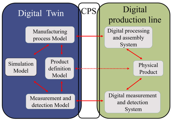
Figure 1.
Digital industrial systems.
Based on this digitalized industrial system, this study designs a digital twin loop system suitable for axial hollow-wall pipes. The digital twin system comprises three sub-loops and one overall loop, as depicted in Figure 2.
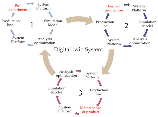
Figure 2.
Digital twin loop system.
- Sub-loop 1: Pre-Production Loop
The purpose of this loop is to test the manufacturing process of the product before actual industrial production and to address potential issues. The steps involve pre-test production, data collection, uploading the data to the platform, simulating and analyzing defect formation mechanisms, and optimizing the design. The optimized design is then sent back for another round of pre-test production until the desired effect is achieved.
- Sub-loop 2: Formal Production and Processing Loop
This loop is based on the ideal design obtained from sub-loop 1 and involves formal production and processing. Unforeseen issues may arise during large-scale production, necessitating real-time monitoring. Problems encountered during actual production are reflected on the digital twin system platform and analyzed for optimization. The optimized design is sent back for industrial production and real-time monitoring until the desired effect is achieved.
- Sub-loop 3: Product Testing and Maintenance Loop
This loop considers the entire lifecycle of the product, including its performance during use. The product undergoes testing, and the data is uploaded to the platform for simulations and design optimizations. The optimized design is sent back for adjustments, and the optimized product undergoes long-term operation, maintenance, and data collection. The collected data is used to optimize the design, which is then sent back to the production end via the platform.
- The Overall Loop
The overall loop encompasses the digital twin system loop and consists of sub-loops 1, 2, and 3. It starts with the ideal design from sub-loop 1, followed by sub-loop 2 and sub-loop 3. Improvements identified in sub-loop 3 are propagated back to sub-loop 1 for further testing and optimization, forming a continuous cycle.
Digital twins enable bidirectional communication between the digital model and the industrial production line, allowing dynamic and real-time monitoring of the product’s performance. By analyzing data collected from sensors during operation, production, manufacturing, and operational maintenance requirements are integrated into the early stages of the product design. This intelligent closed-loop system facilitates design improvement.
3. Establish a Digital Twin of the Pipe End-Forming Process
One of the most common issues encountered during the operational use of buried PVC-U pipes is pipe leakage, particularly at the interfaces between pipe sections. Consequently, conducting research and optimization on the end-forming process of pipes using a digital twin system becomes crucial to enhance the quality of pipe interfaces.
3.1. Pre-Production Test
PVC-U pipes are commonly connected using various methods, with the socket-and-spigot connection being widely preferred due to its convenience and ease of construction. Among the stages of the end-forming process for PVC-U pipes, thermoforming plays a critical role. This process involves deforming one end of the pipe to facilitate piping connection. Numerous researchers have conducted investigations on different techniques for the end-forming process of pipes, as referenced in studies [10,11,12]. These techniques can be categorized, based on the employed method, such as incremental forming [13] and punch press forming [14,15]. They can also be distinguished by the conditions applied, such as cold flaring [16] and hot flaring [17,18]. Furthermore, the number of forming cycles can differentiate between single-cycle flaring and multi-cycle flaring. Considering the material properties of PVC, the socket formation for PVC-U axial hollow-wall pipes typically involves single-cycle punch press forming under heated conditions. The end-forming equipment used in the experimental setup is illustrated in Figure 3, and the step of the end-forming process is depicted in Figure 4.
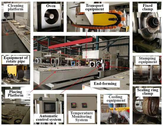
Figure 3.
Production line of the end-forming process.
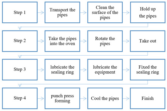
Figure 4.
Steps of the end-forming process.
The quality of the pipe’s end-forming process is influenced by several factors, as illustrated in Figure 4. These factors include the forward rate of the equipment’s punching head, the design of the punching equipment, the friction coefficient between the pipe and the equipment, the end-forming conditions (presence of sealing ring), the heating temperature of the pipe, the heating time, the preheating temperature of the punching head, the ambient temperature, and the cooling temperature of the pipe after end-forming. Among these factors, the change in the pipe’s cross-sectional structure has minimal impact on the first four factors. To minimize the design and construction costs of the axial hollow pipe production line, it is advisable to keep these four factors unchanged, compared to the existing design of the company’s solid-wall pipe end-forming production line. Specifically, the equipment forward rate is set at 100 mm/s, the punching head has a rounded corner design of 3° to reduce stress concentration, lubricating oil is applied to the outer surface of the equipment and rubber ring to reduce the friction coefficient, and a sealing ring is used during the end-forming process to simplify subsequent construction steps and to facilitate the insertion of a steel ring inside the sealing ring to improve its stiffness. However, the change in the pipe’s cross-sectional structure has a significant impact on the last five factors, which require further research to determine the optimal design.
The experimental site for this research is located in Shandong Province, China. The experiments were conducted in November, when the ambient temperature in the factory was approximately 15 °C. Under the conditions of an ambient temperature of 15 °C, with heating temperatures of 225 °C on both the inner and outer sides, the heating time required for a solid-wall PVC-U pipe with an outer diameter of 200 mm and a wall thickness of 8 mm was determined to be 180 s. Considering that the axial hollow-wall pipe has a lower cross-sectional rigidity, compared to the solid-wall pipe, it requires a lower end-forming process temperature. Furthermore, considering that the axial hollow pipe has the same material composition as the solid-wall pipe, but with a thinner wall thickness (the hollow pipe has a wall thickness of 7.5 mm, with 1.5 mm for the outer wall and 2 mm for the inner wall, for an outer diameter of 200 mm, as illustrated in Figure 5), it can be inferred from Equation (1) that the optimal heating time for the hollow pipe, under the same heating temperature conditions, should fall within the range of 50 to 70 s. Therefore, in the pre-production test, six different heating times were set: 40 s, 50 s, 60 s, 70 s, 80 s, and 90 s. To mitigate performance variations among different pipe materials and to reduce the influence of random factors on the experimental results, each test involved one length of axial hollow pipe (6 m) divided into six 1 m segments, which were randomly assigned to six groups. The experiments were repeated five times, and the results were averaged.
Q = C M (T − T0) = C V ρ (T − T0)
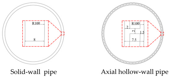
Figure 5.
Schematic diagram of the cross-section of the pipe.
Q: Quantity of heat, C: Specific heat capacity, M: Mass, V: Volume, ρ: Density, T: Final temperature, T_0: Initial temperature. To prevent rapid cooling and its impact on the forming quality of the heated pipes upon contact with the stamping equipment, preheating is required for the stamping equipment. In the case of solid-wall pipes, the preheating temperature for the stamping equipment is generally around 90 °C. However, for hollow pipes, the preheating temperature for the stamping equipment can be appropriately reduced. On the other hand, excessive residual temperature stress can be induced in the pipes, due to a high residual temperature after the flaring process. Therefore, it is necessary to control the temperature at the moment of cooling and detachment of the pipes after the flaring process.
After the heating process, temperature measurements were conducted at intervals of 50 mm within a 400 mm range from the pipe opening, as depicted in Figure 6. The horizontal axis, X, represents the distance from the measurement point to the pipe opening. The results depicted in Figure 6 demonstrate that, in the heating section (0–200 mm), the average temperature of the pipe gradually increased as the heating duration progressed. This temperature variation pattern aligned with Equation (1) mentioned earlier. Additionally, due to the non-enclosed structure of the oven, the temperature decreased as the position in the pipe segment moved closer to the oven outlet. However, the overall temperature remained within an appropriate range. In the non-heating section (200–400 mm), the cooling effect of the surrounding air led to a rapid temperature drop from 73–144 °C to 20–40 °C within the pipe segment. Beyond the 400 mm point, the pipe temperature approached room temperature, and the influence of temperature became negligible.
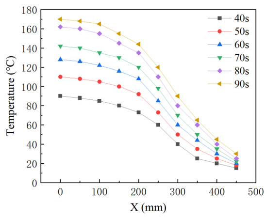
Figure 6.
Temperature variation.
The pipe end heating process is illustrated in Figure 7, wherein the pipe is fed into the oven using a fixture and heated using internal and external radiation heating tubes. In the heating process, the fixture rotates the pipe to ensure uniform heating of the pipe walls at all locations.
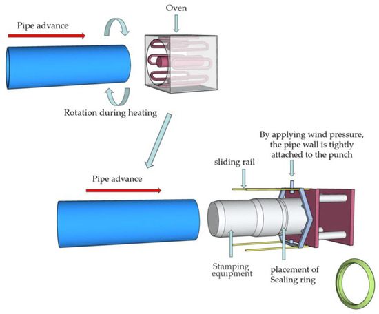
Figure 7.
End-forming diagram.
The expanded mouth forming process is carried out on the heated pipe. The schematic diagram of the end-forming process is illustrated in Figure 7. After heating, the pipe is swiftly moved to the end-forming process area. Firstly, the sealing ring is placed inside the groove of the punching head. Then, the pipe is pushed forward, and the punching head is utilized to expand the pipe diameter. During the end-forming process, the pneumatic pressure loading device on the outer slide rail of the punching head applies air pressure to ensure tight contact between the pipe wall and the punching head; thus, preventing any gaps between the pipe wall and punching head. Figure 8 visually presents different types of defects that were observed during this process. The experimental observations are summarized below:
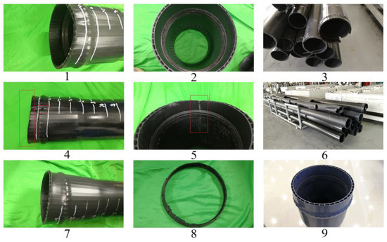
Figure 8.
Defect forms: (1) Small cracks on the inner wall, (2) Whitening on the inner wall, (3) Rupture of pipe end, (4) Small cracks on the outer wall, (5) Through cracks, (6) Sagging, (7) Flanging, (8) Sealing ring deformation, (9) Qualified products.
In the 40 s heating group, the pipe material exhibited whitening on the inner wall diameter changed area of the socket end and small cracks appeared at the expanded section. This was due to insufficient heating of the pipe material, resulting in low elongation at fracture. Consequently, excessive plastic deformation (whitening), and even cracking, occurred during the flaring process, as illustrated in Figure 8(1,2).
In the 50 s heating group, the pipe material’s temperature increased by prolonging the heating time, which reduced the material’s elastic modulus and increased the elongation at fracture; thereby, avoiding inner wall cracking. However, whitening the diameter changed area of the inner wall at the end of the socket still occurred, as depicted in Figure 8(2).
In the 60 s heating group, the pipe material’s elastic modulus further decreased, enhancing its plastic deformation capability. The pipe body exhibited no whitening, cracks, or flanging, indicating that the material was adequately heated and reached the required temperature. The results were ideal, as illustrated in Figure 8(9).
In the 70 s heating group, the pipe material’s inner wall showed no whitening or cracks, but slight flanging occurred. This suggests that excessive heating of the pipe material resulted in a low elastic modulus and decreased stiffness. The sudden change in the sealing ring placement during the flaring process caused outward deformation of the pipe opening, as depicted in Figure 8(7).
In the 80 s heating group, extensive flanging and cracks appeared on the outer wall, with widespread cracking on the inner wall (Figure 8(4,5)). The material lost its ability to recover elasticity after deformation, and its strength was insufficient to support the flaring process. Additionally, the weak point of the sealing ring deformed due to excessive temperature, as depicted in Figure 8(8).
In the 90 s heating group, significant sagging and slight burn marks were observed on the pipe wall. Insufficient stiffness caused the pipe to sag, and partial overheating and carbonization occurred. The subsequent flaring process could not be sustained (Figure 8(3,6)).
The experimental results indicated that, within the range of 15–122 °C, as the temperature increased, the tensile strength and stiffness of PVC pipes decreased, while elongation at fracture increased. Beyond 122 °C, the tensile strength and stiffness of the PVC pipes continued to decrease with increasing temperature, but the elongation at fracture decreased. This was because the thermal vibration of the PVC polymer chains increased with temperature, reducing the intermolecular forces between the chains and resulting in a decline in the overall mechanical properties of the material, but an increase in its ductility. However, when the temperature exceeded 122 °C, the low intermolecular forces were insufficient to resist deformation caused by external forces, leading to a decrease in the material’s ductility (elongation at fracture). The peak value of 122 °C was not fixed and varied depending on the type and proportion of materials used in the pipe production [19,20,21]. Nevertheless, the tendency of the elongation at fracture of this PVC material to initially increase and then decrease with temperature has been confirmed [22,23,24].
The duration of end-forming heating plays a critical role in determining the tensile properties of rigid polyvinyl chloride (PVC) pipes. Based on the experimental results, it was found that a heating time of 60 s was most suitable for achieving the desired outcomes at the ambient temperature (15 °C). Additionally, the preheating temperature of the stamping equipment could be set within a range of 70–80 °C, which met the requirements. However, considering the importance of reducing energy consumption, a preheating temperature of 70 °C was deemed more appropriate. It is crucial to control the temperature for cooling detachment within the range of 35–45 °C to prevent significant cooling shrinkage; thereby, ensuring improved forming quality. Effective temperature control played a vital role in achieving optimal forming quality at the flaring end of the pipe and the diameter changed area at the end of the socket. Furthermore, the subsequent leak tightness test under internal pressure and angular deviation of the axial hollow pipe demonstrated that the quality of these two areas had a direct impact on the pipeline’s overall operational risk resistance.
3.2. Establish a Digital Twin Model
The data gathered from the pre-production experiments was imported into the digital twin system platform, which encompassed interfaces for various modeling and simulation software. This platform empowers researchers to deploy software tailored to their specific requirements. Utilizing the collected data and AutoCAD software, a 1:1 digital twin model of the pipe was generated. Figure 5 illustrates the schematic cross-section of the pipe, showcasing an outer diameter of 200 mm and a wall thickness of 7.5 mm. The outer wall thickness measured 1.5 mm, the inner wall thickness measured 2 mm, the hollow cavity layer thickness measured 4 mm, and the interlayer support thickness measured 2 mm. The pipe included a total of 60 evenly distributed hollow holes along its circumference.
The end-forming process of the pipe was simulated using ABAQUS software, as illustrated in Figure 7, involving two steps. Firstly, the simulation focused on the heating and softening of the pipe material. The length of the pipe segment considered for the simulation was 400 mm, and solid elements were utilized. The material properties are depicted in Table 1.

Table 1.
Material properties.
The variation in the tensile properties of the pipe material with temperature was determined based on the standards GB/T 8804-2003 and GB/T 1040.1-2018. The corresponding curve is depicted in Figure 9.
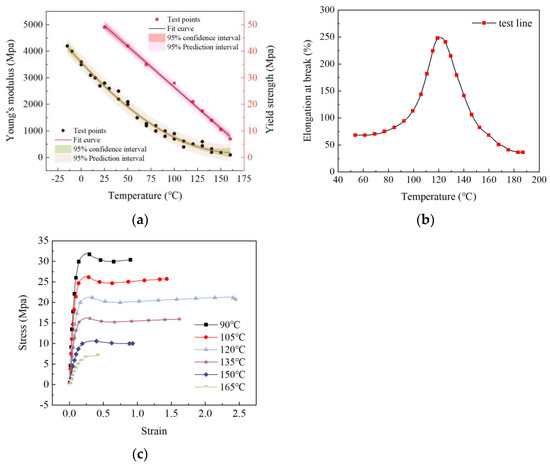
Figure 9.
Temperature−tensile properties of pipes: (a) Temperature−young’s modulus properties of pipes and Temperature−yield strength properties of pipes, (b) Temperature−elongation at break properties of pipes, (c) Stress−strain properties of pipes at different temperatures.
The analysis included a heat transfer step, where the time was determined based on the requirements of each group. To meet the experimental conditions, the initial temperature of the pipe segment was set at 15 °C. The temperature propagated from the pipe mouth towards the far end, with a transfer temperature of 225 °C. Within the last 200 mm section of the pipe segment, surface heat exchange occurred, establishing contact with an ambient temperature of 15 °C. After the heating process was complete, the entire pipe segment underwent a 10 s heat exchange in an environment with a temperature of 15 °C (there was approximately a 10 s gap between the oven heating and the punching press process). The mesh was divided into hexahedral elements, utilizing standard heat transfer elements for the grid attributes. The total number of elements was 1.008 million. The simulation results are illustrated in Figure 10.
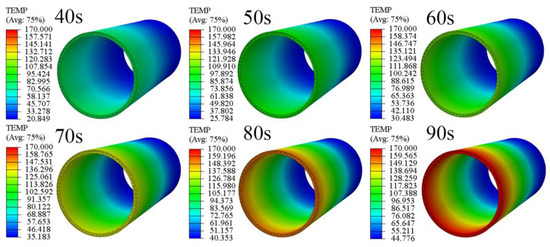
Figure 10.
Simulated cloud map of the heating process.
As illustrated in Figure 11, a comparison between the experimental and simulated temperature variations of the pipe demonstrated certain differences. In the simulated results, the temperature of the pipe in the 0–100 mm section was approximately 0–3 °C higher than the experimental results. This divergence could be attributed to the simulation’s assumption of an ideal sealed heating condition for this section of the pipe. However, in reality, the non-sealed structure of the oven led to some heat dissipation, resulting in a slightly lower actual heating effect compared to the ideal temperature.
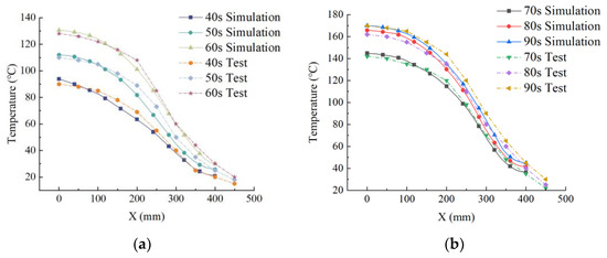
Figure 11.
Comparison between experimental results and numerical simulation results: (a) Comparison of 40s–60s, (b) Comparison of 70s–90s.
Conversely, in the simulated results, the temperature of the pipe in the 100–200 mm section was approximately 0–6 °C lower than the experimental results. This discrepancy arose from the simulation’s assumption that this section of the pipe experiences heating at 225 °C and heat dissipation at an ambient temperature of 15 °C. However, during the actual experiment, the high-temperature operation of the oven caused the surrounding air temperature to exceed 15 °C, resulting in a slightly higher pipe temperature than predicted by the simulation. The slight deviation in the simulated temperature of the 200–300 mm section, compared to the experimental results, can also be attributed to the aforementioned variations in heat dissipation conditions. However, in the case of the 300–400 mm section, the simulated and experimental results demonstrated good agreement. Overall, the simulation error was negligible, with a value of less than 5%. This indicated that the model satisfactorily met the required criteria.
In the second step, the simulation of the flaring process for the softened pipe segment was performed, as illustrated in Figure 12. The stamping equipment of the actual expansion device was modeled at a 1:1 scale. Figure 7 illustrates the structure of the expansion equipment used for the pipe. In this simulation, the sealing ring was represented by solid elements, while the punch head was considered to be an analytically rigid body. To analyze this process dynamically, a temperature–displacement coupling approach was employed. The contact between the stamping equipment surface and the inner wall of the pipe, as well as between the inner wall of the pipe and the sealing ring, was modeled as frictional contact. The coefficient of friction was determined according to the specifications outlined in GB/T 10006-2021, as depicted in Table 2.
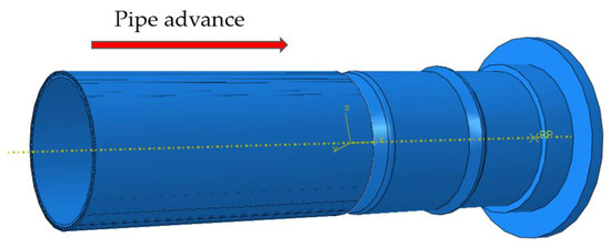
Figure 12.
End-forming numerical simulation.
Table 2.
Frictional coefficient.
The punch was programmed to move at a constant speed, covering a forward distance of 220 mm within a time duration of 2.2 s. In the pipe’s 0–220 mm section, a uniform pressure of 0.1 MPa was uniformly applied to the outer side of the pipe. This pressure served as a substitute for the pneumatic load used in the experimental setup. The mesh configuration utilized temperature–displacement elements, maintaining the same number of elements as in the previous step. The simulation results are presented in Figure 13.
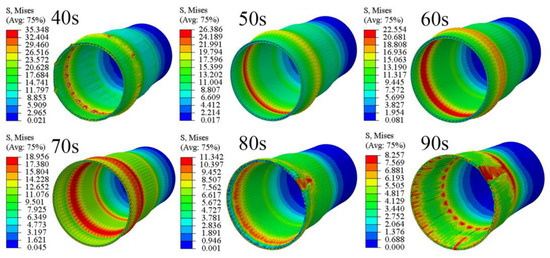
Figure 13.
Simulated cloud map of the flaring process.
Based on the combination of Figure 9 and Figure 13, it can be observed that after 40 s of heating, the temperature in the expanded section of the pipe ranged from 73 °C to 90 °C. At this temperature, the yield strength of the pipe material was 35.348 MPa. The presence of small cracks on both the inner and outer walls at the sealing ring placement indicated the maximum strain at this location, with some elements exceeding the fracture elongation rate of the material at this temperature (70–87%). This conclusion aligned with the experimental results.
Following 50 s of heating, the temperature in the expanded section of the pipe increased to 92–110 °C. The yield strength decreased to 26.386 MPa, while the fracture elongation rate increased to 94–181%. No cracks were observed in the pipe section at this point, and the quality of the end-forming met the requirements.
After 60 s of heating, the temperature in the expanded section of the pipe reached 108–128 °C. The yield strength further decreased to 22.554 MPa, while the fracture elongation rate rapidly increased to 165–250%. The higher fracture elongation rate indicated excellent ductility of the pipe material. Within the temperature range of 73–122 °C, the fracture elongation rate of the pipe material increased with the temperature. Considering the temperature drop caused by air cooling during the actual expansion process, selecting a 60 s heating time could effectively prevent the cracking issues observed in the 40 s heating model.
After 70 s of heating, the temperature in the expanded section of the pipe rose to 130–142 °C. The yield strength decreased to 18.956 MPa, and the fracture elongation rate decreased to 124–192%. At this stage, the pipe end exhibited outward bending and deformation of the hollow structure at the pipe opening, but no cracks were observed. This phenomenon indicated that, although the fracture elongation rate decreased, it still met the requirements. However, the increase in temperature led to a rapid decrease in the elastic modulus, causing the cross-sectional stiffness of the pipe material to no longer meet the requirements for expansion deformation, resulting in deformation and damage to the pipe opening structure.
After 80 s of heating, the temperature in the expanded section of the pipe increased to 143–162 °C. At this stage, the yield strength further decreased to 11.342 MPa, and the fracture elongation rate decreased rapidly to 65–106%. Large deformation cracks appeared when the pipeline expanded to the position of the sealing ring placement, and the structure of the pipe opening was damaged with significant folding. The low elastic modulus and fracture elongation rate prevented the pipe material from withstanding the deformation caused by the expansion, which aligned with the occurrence of cracks penetrating the inner and outer walls and the extensive flaring of the pipe opening observed in the experiments.
After 90 s of heating, the temperature in the expanded section of the pipe rose to 155–170 °C. The yield strength decreased to 8.257 MPa, and the fracture elongation rate decreased to 41–75%. In the 90 s group, cracking occurred at the early stage of expansion due to an excessively low fracture elongation rate, resulting in the termination of the calculation.
The experimental and simulation studies revealed that the temperature–fracture elongation rate performance of the pipe material had a significant impact on the expansion-forming quality of the PVC-U hollow pipes. The numerical simulation results aligned with the experimental findings, and, based on this model, a preliminary digital twin was established. Subsequently, the digital twin was fed back to the production end of the factory for industrial production through the digital twin platform. Real-time monitoring and adjustments were performed, based on various production data through integration with the automation monitoring system, resulting in a yield rate of the pipe of up to 95% for the qualified products.
4. Testing and Maintenance of Axial Hollow Pipe Products
In industrial production, the establishment of digital twins necessitates product testing feedback and product maintenance management. The primary cause of damage to buried pipelines is leakage resulting from uneven settlement of the foundation at the pipeline interfaces. This issue is particularly prominent in agricultural water management, where uneven soil saturation, changes in soil compaction during tillage and seeding, and mechanical labor-induced stress commonly result in significant settlement problems surrounding buried pipelines. Buried pipelines in the agricultural water management field experience prolonged exposure to both angular displacement and static hydraulic pressure. At this stage, the performance of pipe joints is crucial, as it determines the service life and risk resistance of the pipeline. Typically, agricultural water supply and drainage pipelines are designed to withstand internal water pressures below 0.4 MPa. As a result, angular displacement has a significantly greater impact on pipeline deformation than water pressure. Thus, when evaluating the performance of pipe joints, angular displacement sealing tests are more effective than hydrostatic testing.
4.1. Establish a Digital Twin Model
To validate the sealing performance of the produced pipeline interfaces, a leak tightness test under internal pressure and angular deviation was conducted. The test utilized the JJHBT pipe material static hydraulic testing machine manufactured by JJ-TEST for water pressure loading. Strain gauges, displacement sensors, and inclinometers were employed as monitoring equipment, connected to the CHHP-DJ dynamic signal testing and analysis system provided by NANJING HOPE TECHCO., LTD for data acquisition. The experimental procedure was as follows:
- The assembled pipeline was subjected to a water pressure of 0.4 MPa;
- Once the water pressure stabilized, angular displacement loading was applied to the pipe body incrementally, with each increment set at 0.5°;
- After each loading step, the angular displacement was maintained at a constant value for 60 min to observe any signs of leakage;
- If leakage occurred during the observation period, the test was halted. Conversely, if no leakage was detected, the test continued.
The experimental design is depicted in Figure 14.
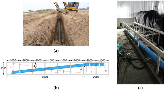
Figure 14.
The leak tightness test under internal pressure and angular deviation: (a) Practical application, (b) Schematic diagram, a Deflection displacement loading point, b Displacement meter, c Inclinometer, d Welding point, e Hydrostatic loading point. (c) Photo of the test.
In numerical simulations, the pipe material is considered an elastoplastic material, and its elastoplastic behavior is determined based on the standards GB/T 8804-2003 and GB/T 1040.1-2018, as illustrated in Figure 15.
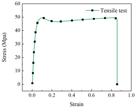
Figure 15.
Characteristic curve of Tensile test.
The chosen mesh elements for the pipe material were 8-node linear brick-reduced integration elements (C3D8R). On the other hand, the sealing ring was composed of a hyper-elastic material, for which the Mooney–Rivlin material model was employed. The sealing ring mesh elements were 8-node linear brick hybrid-reduced integration elements (C3D8RH), and a static general analysis approach was utilized for the simulation. The simulation consisted of three steps, as illustrated in Figure 16. Firstly, the straight pipe was inserted into the socket joint. Next, a uniform pressure of 0.4 MPa was applied to both the inner surface of the connection point of the pipe and the inner surface of the straight pipe. In the third step, an angular displacement was applied to the straight pipe.
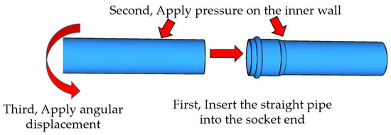
Figure 16.
Numerical simulation.
4.2. Analyze Defects and Optimize the Design
Figure 17 displays the strain–angle characteristic curve of the socket end pipe wall, obtained from experiments and simulations. The results indicated that, in the range of 1–8 degrees of offset angle, the mechanical behavior of the pipe joint was primarily influenced by the frictional force between the pipe wall and the sealing ring, the fit between the chamfered end of the straight pipe and the diameter changed area at the end of the socket, and the structural mechanical performance of the pipe socket end. These factors collectively contributed to resisting the mechanical effects of the angular deviation on the pipe joint and ensuring sealing integrity.
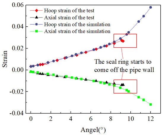
Figure 17.
Variation of strain at the end of the pipe.
As the offset angle increased to the range of 9−12 degrees, the maximum stress at the pipe joint reached 49 MPa, entering the plastic deformation stage. The contact between the pipe wall and the sealing ring gradually diminished, resulting in a reduction in frictional force. Consequently, the seal integrity of the joint started to gradually diminish as well. The fit between the chamfered end of the straight pipe and the diameter changed area at the end of the socket, and the structural mechanical performance of the pipe’s socket end, became the primary factors resisting deformation.
During the experiments, slight leakage occurred at the pipe joint at this stage, leading to the termination of the test. In contrast, during simulations, the strain rate at the pipe joint rapidly increased at this point.
Figure 18 illustrates a cloud map of the pipe joint simulation. Within the figure, the term “S. Mises” indicates that the stress value corresponded to the equivalent stress value calculated, based on the Mises yield criterion. The Mises yield criterion follows the fourth strength theory of material mechanics, also known as the theory of distortion energy. This theory considers distortion energy as the primary cause of material flow failure. In other words, when the equivalent stress at a particular point within the object reaches the yield limit under specific deformation conditions, the point enters a plastic state.
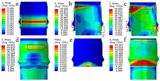
Figure 18.
Simulated cloud map of pipe joint: (a) Stress during straight pipe insertion, (b) An 8° deviation angle, (c) A 12° deviation angle, (d) Stress diagram of the outer side, (e) PEEQ diagram of the socket end, (f) Stress diagram of the outer side.
Furthermore, in Figure 18, the term “PEEQ” represents the equivalent plastic strain, which signifies the cumulative plastic strain resulting from the entire deformation process. It is computed as the sum of the absolute values of plastic strain. PEEQ provides an intuitive representation of the model’s plastic strain condition after being subjected to stress.
The simulated cloud map reveals that, when the straight pipe was inserted into the socket end, the stress concentration mainly occurred in the region where the sealing ring was positioned. However, the magnitude of this stress was relatively low, reaching a maximum value of only 0.246 MPa (Figure 18a). Consequently, this residual stress was unlikely to have a significant impact on the subsequent utilization of the pipeline. When the angular deviation and static water pressure were applied simultaneously, the socket end of the pipe material exhibited a quality control zone, characterized by extreme stress. This zone was observed on the offset angle side of the pipe joint (Figure 18e) and in the outer region where the pipe diameter deformed (Figure 18d). In these areas, the pipe wall underwent significant compression deformation. Importantly, this quality control zone aligned with the quality control zone identified during the pipe end-forming process test. Thus, it reaffirmed the significance of appropriate processing temperature design in ensuring the quality of the pipe material product.
The sealing performance of the offset angle test was primarily influenced by the frictional force provided by the sealing ring, the deformation of the socket end of the pipe, and the fit of the socket joint. The sealing ring plays a crucial role in ensuring sealing integrity. However, on the offset angle outside, the pressure between the straight pipe and the sealing ring decreases as the offset angle increases, leading to a reduction in the sealing performance offered by the sealing ring. To improve the offset angle sealing performance of the pipeline, one approach is to increase the thickness of the raised section of the sealing ring. By doing so, the sealing performance can be enhanced. However, there is a limit to how much the thickness of the sealing ring can be increased. Excessively thick sealing rings may pose difficulties during pipe connection. In the offset angle test, increasing the thickness of the raised section of the sealing ring from 13 mm to 16 mm, while maintaining the same material, resulted in only a modest increase in maximum pressure to 0.289 MPa during the socket joint connection. However, the pipe joint sealing integrity remained intact under the observed 12° offset angle in the test.
In contrast to normal interface static hydraulic tests, where sealing integrity relies on the sealing ring’s performance, the leak tightness test under internal pressure and angular deviation emphasizes the structural mechanical strength of the socket end of the pipe to ensure leak resistance under offset angle pressure. The structural mechanical performance of the socket end determines the strain magnitude caused by the offset angle displacement, which, in turn, affects the pressure experienced by the sealing ring.
Appropriate processing temperature plays a vital role in preventing excessive stretching during end-forming. It ensures the wall thickness and material compactness of the expanded section, which ultimately impacts the pipeline’s resistance to risks. The fit of the socket joint should also be considered. In the offset angle test, noticeable curling and flanging occurred at the chamfered end of the straight pipe (Figure 18c5). This was attributed to extrusion between the chamfered end of the straight pipe and the diameter changed area of the inner wall at the end of the socket. The wall thickness of the hollow pipe was smaller than that of the solid wall pipe, leading to reduced stiffness at the chamfered end of the straight pipe, due to the decreased wall thickness. Therefore, control of the length at the chamfered end of the straight pipe also affects the pipeline’s performance during engineering use. To address this issue, without altering the chamfer slope, the chamfer length could be modified from the original design of 30 mm to 20 mm. This increased the wall thickness at the end of the straight pipe and created an additional 10 mm of reserved space between the pipe end and the diameter changed area of the inner wall at the end of the socket. This modification effectively resolved the problem of curling and flanging at the pipe end. After providing the optimized design to the production side and testing the newly designed and produced products, the results met expectations.
After that, further optimization and verification of product operation and maintenance are conducted through actual use and long-term monitoring. Specifically, the optimized product is deployed in practical operation, where the utilization of various data collection devices enables the monitoring of operational data. During the actual operation and maintenance phases, if any issues arise, the corresponding digital twin model is modified, based on the collected data. The optimized model is then reintegrated into the production process, establishing a closed-loop cycle of continuous improvement.
This intelligent closed-loop system ensures the long-term operation of the pipeline by incorporating real-time data monitoring and feedback. By iteratively refining the digital twin model, based on observed operational data, potential problems or inefficiencies can be promptly identified and addressed. This iterative process not only improves the performance of the pipeline but also enhances its reliability and longevity.
5. Discussion
By establishing a digital twin system for axial hollow-wall pipes, this study successfully determined the optimal processing and production conditions for a 200 mm outer diameter axial hollow-wall pipe. Consequently, it significantly enhanced the production and processing efficiency of axial hollow-wall pipes, leading to improved performance in the domain of agricultural irrigation and drainage. The cyclic process facilitated by the digital twin system, involving production, simulation feedback, and reproduction, provided an efficient and convenient method for enhancing pipe industry production. The findings of this study unequivocally affirm the positive impact of establishing a digital twin system in the advancement of the digital industry and smart agriculture. Furthermore, the outcomes of this research serve as a valuable reference for future intelligent development of both industry and agriculture.
6. Conclusions
In order to ensure the long-term reliability of buried pipelines for agricultural irrigation and drainage, a digital twin system was developed specifically for the axial hollow-wall pipes industry, with applicability to the agricultural water conservancy sector. This system aimed to address the challenges associated with the end-forming process of pipes and to enhance the sealing performance when dealing with offset angles. Through the implementation of the digital twin system, significant improvements were achieved in production efficiency and product optimization capabilities within the pipeline industry. Consequently, the system plays a crucial role in ensuring the sustained operation and maintenance of pipelines over an extended period.
A digital twin system was successfully implemented for the axial hollow pipe industry, leading to significant improvements in the production efficiency of the end-forming process within the production line. As a result, the yield rates of the pipes were up to 95% for qualified products. Furthermore, the system’s intelligent closed-loop feedback mechanism and design enhancements played a crucial role in ensuring the long-term operation and maintenance of the pipelines; thereby, further enhancing their reliability.
Through the analysis conducted using the digital twin system, optimal parameters were determined for achieving the desired quality of end-forming in a 200 mm outer diameter axial hollow pipe. Under the specified conditions of the ambient temperature of 15 °C and heating both the inner and outer sides of the pipe to 225 °C, it was found that the ideal end-forming quality could be achieved by following specific guidelines. These guidelines include a heating time of 60 s, setting the preheating temperature of the stamping equipment at 70 °C, and employing a temperature range of 35–45 °C for the cooling and detachment processes of the pipe. These findings serve as valuable insights for ensuring successful end-forming of axial hollow pipes within specified parameters.
The digital twin system analysis revealed that enhancing the sealing performance of the socket joint could be achieved by increasing the thickness of the raised section of the sealing ring. Specifically, increasing the thickness from 13 mm to 16 mm resulted in improved sealing capabilities, particularly when dealing with the leak tightness under internal pressure and angular deviation in the pipeline. Importantly, this adjustment did not negatively impact the installation efficiency of the socket joint. Therefore, by appropriately increasing the thickness of the raised section, both the sealing performance and overall functionality of the socket joint in the pipeline system could be enhanced.
The digital twin system analysis revealed that the interface performance of the pipeline under offset angles is influenced by the length of the chamfer and the space reserved between the chamfered end of the straight pipe and the diameter changed area of the inner wall at the end of the socket. To address the issue of curling and flanging at the end of the pipe, an optimization of the chamfer length was conducted. By reducing the chamfer length from the initial design of 30 mm to 20 mm, the problem was successfully resolved. This optimization resulted in improved pipeline performance and mitigated the undesirable effects of offset angles on the pipe’s end, ultimately enhancing the overall functionality of the pipeline system.
The implementation of the digital twin system in the agricultural irrigation and drainage pipeline industry offers substantial advantages, including cost reduction, efficiency improvement, and operational assurance in agriculture. The adoption of digital twin technology is a prominent trend in intelligent manufacturing, and its integration across various industries is already underway.
Author Contributions
Conceptualization, Z.G. and Y.Y.; methodology, Z.G.; software, Z.G.; validation, Z.G. and W.J.; formal analysis, Z.G.; investigation, Z.G.; resources, Z.G.; data curation, Z.G.; writing—original draft preparation, Z.G.; writing—review and editing, Z.G. and C.S.; visualization, Z.G.; supervision, Z.G.; project administration, Z.G.; funding acquisition, S.H. All authors have read and agreed to the published version of the manuscript.
Funding
This work was funded by the Key Program of the National Natural Science Foundation of China (grant number 52130901) and the Innovation Group Science Foundation of the Natural Science Foundation of Chongqing, China (grant number cstc2020jcyj-cxttX0003).
Institutional Review Board Statement
Not applicable.
Informed Consent Statement
Not applicable.
Data Availability Statement
Not applicable.
Conflicts of Interest
The authors declare no conflict of interest.
References
- Lu, Y.; Liu, C.; Kevin, I.; Wang, K.; Huang, H.; Xu, X. Digital Twin-driven smart manufacturing: Connotation, reference model, applications and research issues. Robot Cim.-Int. Manuf. 2020, 61, 101837. [Google Scholar] [CrossRef]
- Qi, Q.; Tao, F.; Hu, T.; Anwer, N.; Liu, A.; Wei, Y.; Wang, L.; Nee, A. Enabling technologies and tools for digital twin. J. Manuf. Syst. 2021, 58, 3–21. [Google Scholar] [CrossRef]
- Tao, F.; Xiao, B.; Qi, Q.; Cheng, J.; Ji, P. Digital twin modeling. J. Manuf. Syst. 2022, 64, 372–389. [Google Scholar] [CrossRef]
- Wu, J.; Yang, Y.; Cheng, X.; Zuo, H.; Cheng, Z. The development of digital twin technology review. In Proceedings of the 2020 Chinese Automation Congress (CAC), Shanghai, China, 6–8 November 2020; IEEE: Piscataway, NJ, USA; pp. 4901–4906. [Google Scholar] [CrossRef]
- Wright, L.; Davidson, S. How to tell the difference between a model and a digital twin. Adv. Model. Simul. Eng. Sci. 2020, 7, 1–13. [Google Scholar] [CrossRef]
- Alves, R.G.; Maia, R.F.; Lima, F. Development of a Digital Twin for smart farming: Irrigation management system for water saving. J. Clean. Prod. 2023, 388, 135920. [Google Scholar] [CrossRef]
- Nasirahmadi, A.; Hensel, O. Toward the next generation of digitalization in agriculture based on digital twin paradigm. Sensors 2022, 22, 498. [Google Scholar] [CrossRef]
- Sreedevi, T.R.; Kumar MB, S. Digital Twin in Smart Farming: A categorical literature review and exploring possibilities in hydroponics. Accthpa 2020, 2020, 120–124. [Google Scholar] [CrossRef]
- Chaux, J.D.; Sanchez-Londono, D.; Barbieri, G. A digital twin architecture to optimize productivity within controlled environment agriculture. Appl. Sci. 2021, 11, 8875. [Google Scholar] [CrossRef]
- Yeh, F.H. Study of tube flaring forming limit in the tube flaring process. J. Strain. Anal. Eng. 2007, 42, 315–324. [Google Scholar] [CrossRef]
- Kwan, C.T. Investigation on Elliptic-Shaped Flaring Process of Metal Tube with Finite Element Method, Key Engineering Materials. Trans. Tech. Publ. 2008, 364, 949–954. [Google Scholar] [CrossRef]
- Chen, T.C.; Ceng, W.K. Experimental and numerical analysis of stainless steel microtube in flaring process. Math. Probl. Eng. 2014, 2014, 1–8. [Google Scholar] [CrossRef]
- Movahedinia, H.; Mirnia, M.J.; Elyasi, M.; Baseri, H. An investigation on flaring process of thin-walled tubes using multistage single point incremental forming. Int. J. Adv. Manuf. Tech. 2018, 94, 867–880. [Google Scholar] [CrossRef]
- Huang, Y.M. Elasto-plastic finite-element analysis of the axisymmetric tube-flaring process with conical punch. Int. J. Adv. Manuf. Tech. 2001, 18, 390–398. [Google Scholar] [CrossRef]
- Daxner, T.; Rammerstorfer, F.G.; Fischer, F.D. Instability phenomena during the conical expansion of circular cylindrical shells. Comput. Method. Appl. M 2005, 194, 2591–2603. [Google Scholar] [CrossRef]
- Aghabeyki, F.; Mirnia, M.J.; Elyasi, M. Cold and warm flaring of thin-walled titanium tube using single-point incremental forming. Int. J. Adv. Manuf. Tech. 2021, 114, 3357–3376. [Google Scholar] [CrossRef]
- Lucchi, M.; Lorenzini, M. Characterization of the radiative heating stage in the end-forming process of PVC pipes. Therm. Sci. Eng. Prog. 2018, 7, 213–220. [Google Scholar] [CrossRef]
- Lucchi, M.; Lorenzini, M. Effects of pipe angular velocity and oven configuration on tube temperature distribution in the radiative heating of PVC pipes. Int. J. Energy Environ. E 2018, 9, 123–134. [Google Scholar] [CrossRef]
- Lou, M.; Wang, Y.; Tong, B.; Wang, S. Effect of temperature on tensile properties of reinforced thermoplastic pipes. Compos. Struct. 2020, 241, 112119. [Google Scholar] [CrossRef]
- Pulngern, T.; Chitsamran, T.; Chucheepsakul, S.; Rosarpitak, V.; Patcharaphun, S.; Sombatsompop, N. Effect of temperature on mechanical properties and creep responses for wood/PVC composites. Constr. Build. Mater. 2016, 111, 191–198. [Google Scholar] [CrossRef]
- Merah, N.; Irfan-ul-Haq, M.; Khan, Z. Temperature and weld-line effects on mechanical properties of CPVC. J. Mater. Process Tech. 2003, 142, 247–255. [Google Scholar] [CrossRef]
- Amorim, F.C.; Souza, J.F.B.; Mattos, H.S.D.C.; Reis, J.M.L. Temperature effect on the tensile properties of unplasticized polyvinyl chloride. SPE Polym. 2022, 3, 99–104. [Google Scholar] [CrossRef]
- Hitt, D.J.; Gilbert, M. Tensile properties of PVC at elevated temperatures. Mater. Sci. Tech. 1992, 8, 739–746. [Google Scholar] [CrossRef]
- Povolo, F.; Schwartz, G.; Hermida, É.B. Stress relaxation of PVC below the yield point. J. Polym. Sci. Pol. Phys. 1996, 34, 1257–1267. [Google Scholar] [CrossRef]
Disclaimer/Publisher’s Note: The statements, opinions and data contained in all publications are solely those of the individual author(s) and contributor(s) and not of MDPI and/or the editor(s). MDPI and/or the editor(s) disclaim responsibility for any injury to people or property resulting from any ideas, methods, instructions or products referred to in the content. |
© 2023 by the authors. Licensee MDPI, Basel, Switzerland. This article is an open access article distributed under the terms and conditions of the Creative Commons Attribution (CC BY) license (https://creativecommons.org/licenses/by/4.0/).