Article

Study of the Overlying Strata Movement Law for Paste-Filling Longwall Fully Mechanized in Gaohe Coal Mine

1
State Key Laboratory of Coal Resources and Safe Mining, School of Mines, China University of Mining and Technology, Xuzhou 221116, China
2
Shanxi Cumt Backfill Technology Ltd., Changzhi 046000, China
3
Shandong Energy Zaozhuang Mining (Group) Co., Ltd., Zaozhuang 277000, China
*
Author to whom correspondence should be addressed.
Appl. Sci. 2023, 13(14), 8017; https://doi.org/10.3390/app13148017
Submission received: 18 May 2023 / Revised: 25 June 2023 / Accepted: 7 July 2023 / Published: 9 July 2023
(This article belongs to the Special Issue Advanced Backfill Mining Technology)

Abstract

:
Green mining plays a vital role in achieving environmentally friendly and ecologically sound mining practices. In domestic mining areas, the coal mining method is gradually transitioning from collapse mining to filling mining. Paste filling has been proven effective in controlling surface deformation, although the understanding of its underlying control mechanisms remains incomplete. This study focuses on the E1302 paste-filling working face at Shanxi Gaohe Energy Co., Ltd. and conducts a comprehensive investigation into the movement patterns of overlying strata in longwall fully mechanized mining with paste filling. Through mathematical analysis, a mechanical model for overburden movement in paste-filling faces is established, and the movement behavior of overburden is studied through numerical simulations. Field measurements are conducted to analyze the primary influencing factors of overburden movement, while surface subsidence monitoring is employed to analyze the subsidence characteristics of paste-filling faces. The research reveals that the deflection formula for the roof behind the paste-filling face follows a unitary quartic equation. The key factors influencing significant roof subsidence in filling faces include the filling step distance, filling body strength, and filling rate. Compared to traditional caving mining, filling mining exhibits reduced stress concentration, a smaller range of stress influence, and less deformation in the surrounding rock. The coefficient of gentle subsidence for the overlying rock in filling mining is approximately one-tenth of that in caving mining. The development of cracks in filling mining can be divided into three stages: initial crack propagation, crack recompaction, and stable maintenance of cracks. Notably, the progression of advanced cracks assumes a “sail-shaped” pattern, and the area of crack recompaction is located above the rear side of the excavation. Cracks behind the working face only appear in the basal roof rock layer. When the filling rate in longwall fully mechanized mining with paste filling exceeds 94%, the top plate of the filling working face remains intact but exhibits bending and sinking. The sinking of the top plate increases exponentially with the filling step distance, and approximately 80% of the filling body’s deformation occurs within 20 m after filling. Following backfilling mining, the stability period of the overlying rock is significantly shortened compared to caving mining, resulting in a relatively gentle movement without an active surface movement phase. After six months of backfilling, the overlying rock settles steadily and consistently. The subsidence coefficient for backfilling mining is 0.065, with a maximum surface subsidence of 215 mm. These findings highlight the successful control of surface subsidence. The research outcomes provide an effective theoretical foundation and research direction for predicting overburden movement and surface subsidence in paste-filling faces.

1. Introduction

The recoverable reserves of coal are decreasing increasingly, especially in developed eastern regions, because it is non-renewable energy. Coal mining encounters more serious pressure with the development of the economy [1,2]. The traditional mining mode under buildings has a low recovery rate, which results in the waste of coal resources. It also pollutes the ecological environment, etc. [3,4], and seriously affects the sustainable development of mines. Therefore, environmentally friendly mining technology is needed to solve the above problems. The concept of green mining has been focused on by the mining industry. Many scientific and technological workers have studied the system and proposed some technologies like paste-filling mining, gangue-filling mining, high-water-filling mining, water retention mining, and separation zone-filling mining [5,6,7,8]. Paste-filling mining technology, as an important mining method in the green mining system [9,10], is being practiced in vast coal mining areas.
Paste-filling technology was first applied in metal mines. It mainly experienced four development stages: dry filling, water–sand filling, low-concentration cemented filling, and paste filling, according to the development of filling technology [11,12]. The primary purpose of the earliest filling was to dispose of solid wastes such as tailings and coal gangue. Poland, Germany, and other countries adopted water–sand filling technology to re-mine coal under buildings and protect the land surface buildings by the 1940s and 1950s. The problem of coal mining and coal gangue treatment under buildings is prominent in eastern China in the 21st century, so the filling mining technology enters its trial in eastern China and is gradually applied in coal mines. China’s paste-filling mining technology was first successfully tested in Taiping Coal Mine in May 2006. Later, it was gradually applied in the Daizhuang Coal Mine and Xuchang Coal Mine of Zibo Group in Shandong Province in 2009 after summarizing technical experience and exploring filling methods under various geological conditions. Experiments have been conducted on coal mining with water and secondary filling mining technology of strip coal pillars under buildings. The research direction of paste-filling coal mining technology has been explored through years of research [13,14,15].
Researchers have studied paste-filling mining-related technologies. Sun studied the overlying strata movement law of paste-filling mining [16]. Qu used void conservation theory to study the rock layer control and filling technology of paste-filling mining [17]. Chang studied the overlying strata deformation and earth surface subsidence theory of filling mining based on the elastic foundation beam theory [18]. Guo studied the overlying strata movement law of filling mining by numerical simulation [19,20,21,22,23]. However, the above studies are conducted on the overlying strata movement of filling the working surface. Research is at the early stage of the paste-filling technology of the industrial demonstration site. The filling working face has a low efficiency of recycling strip coal pillars or filling in the period. Therefore, the law of overlying strata movement in filling mining cannot be demonstrated systematically. The paste-filling mining technology has been further improved to a higher level of large mining amount, efficient filling, and intelligent control after decades of technical development.
Gaohe Energy’s longwall paste-filling working face adopts the latest research of isolation filling support with the present high efficiency. It comes with a large displacement filling system and a reasonable proportion of filling materials. The overall filling mining efficiency has been increased by more than two times, and the annual filling mining capacity has reached 1 million tons. This study focuses on investigating the movement patterns of longwall fully mechanized paste-filling overburden in the context of the industrial application of high-efficiency filling mining at Gaohe Coal Mine. The research conducted in this paper holds significant importance in enriching and improving the theoretical framework of paste-filling mining. It not only provides an effective theoretical foundation and research direction for predicting overburden movement and surface subsidence in paste-filling working faces but also supplements the theoretical and practical basis for the widespread adoption of paste filling in mines across China. The findings of this study offer valuable guidance for promoting environmentally friendly mining practices and supporting the green construction of mines in China.

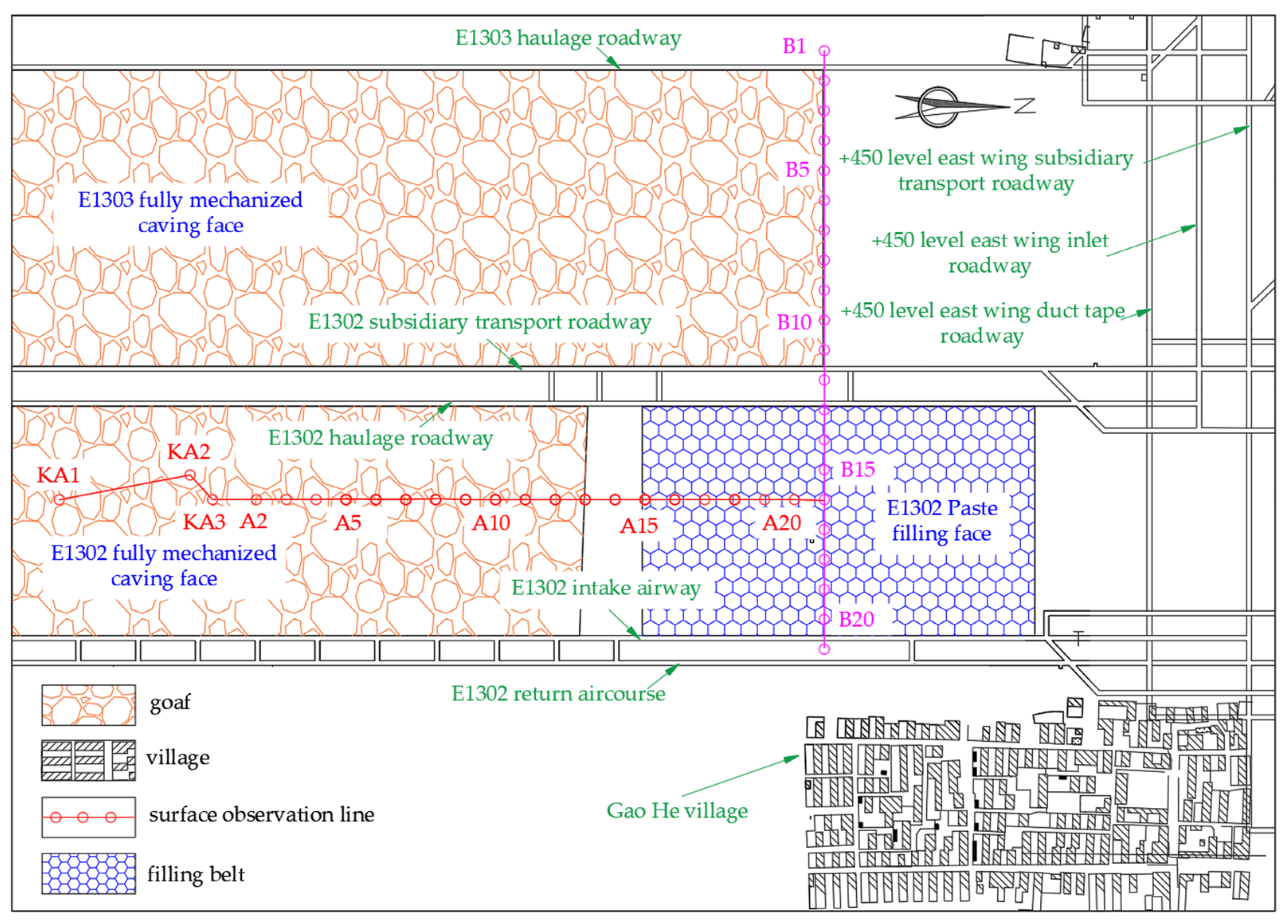
2. Engineering Background

Shanxi Gaohe Energy Co., Ltd., China. is a large coal mine with a total coal amount under buildings of 372 million tons. There are 38 coal villages in the well field, and Song Village Industrial Park in Changzi County is in the middle. The Taijiao Railway and the special railway line of the mine cross the well field, with 1.5 million tons of gangue being discharged every year. Paste-filling mining technology is applied to relieve the coal quantity issue and deal with the gangue problem.
The project of Gaohe Energy mechanized paste-filling was put into operation in 2020, with the filling system capacity reaching 500 m3/h. The filling working face of the initial mining is E1302, which is the village protective coal pillar; the inclined length of the working face is 230 m; the advancing length is 395 m; and the mining height is 3.5 m. Figure 1 lists the working face layout. The average thickness of the coal seam in this region is 6.6 m; the average buried depth is 440 m; and the inclination angle of the coal seam is 1–4°. No collapse column, fault, and other structures are found in the area, and the occurrence of the coal seam in this area is good.
The upper roof is composed of siltstone and fine-grained sandstone, and has a thickness of 8.15 m. The immediate roof is composed of fine-grained sandstone and siltstone with a thickness of 7.51 m. The false roof is mudstone with a thickness of 0.34 m, and the immediate floor is mudstone with a thickness of 0.45 m; the hard floor is composed of siltstone, mudstone, siltsand, sandy mudstone, and siltstone, with a thickness of 14.95 m.
The working face adopts a longwall fully mechanized coal mining arrangement. A specialized filling hydraulic support is used to support the roof. The filling support moves forward after the mining of the shearer; the roof of the working face does not collapse; the area to be filled is formed behind the working face. Next, the area to be filled is sealed and isolated, and all the goaf is filled with qualified paste in time. A supporting system is formed by coupling coal in front of the working face, filling support, and the filling paste in the goaf. It controls earth surface subsidence and avoids resettling villages during mining (see Figure 2).

3. Mechanical Analysis of Overlying Rock Movement of the Filled Working Face

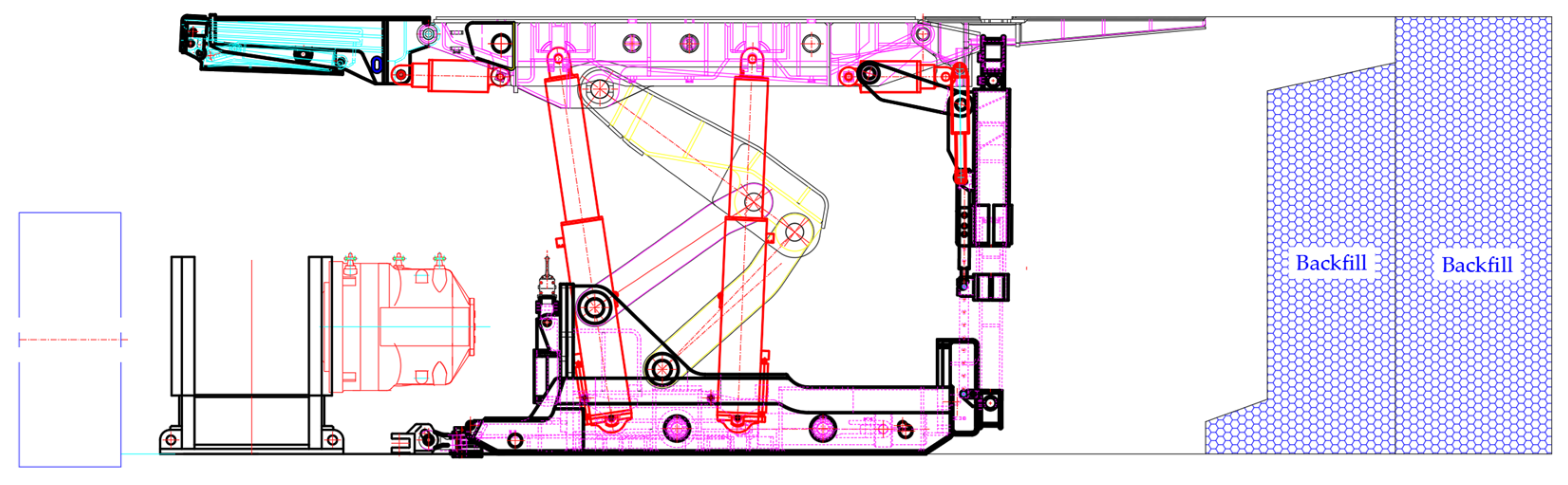
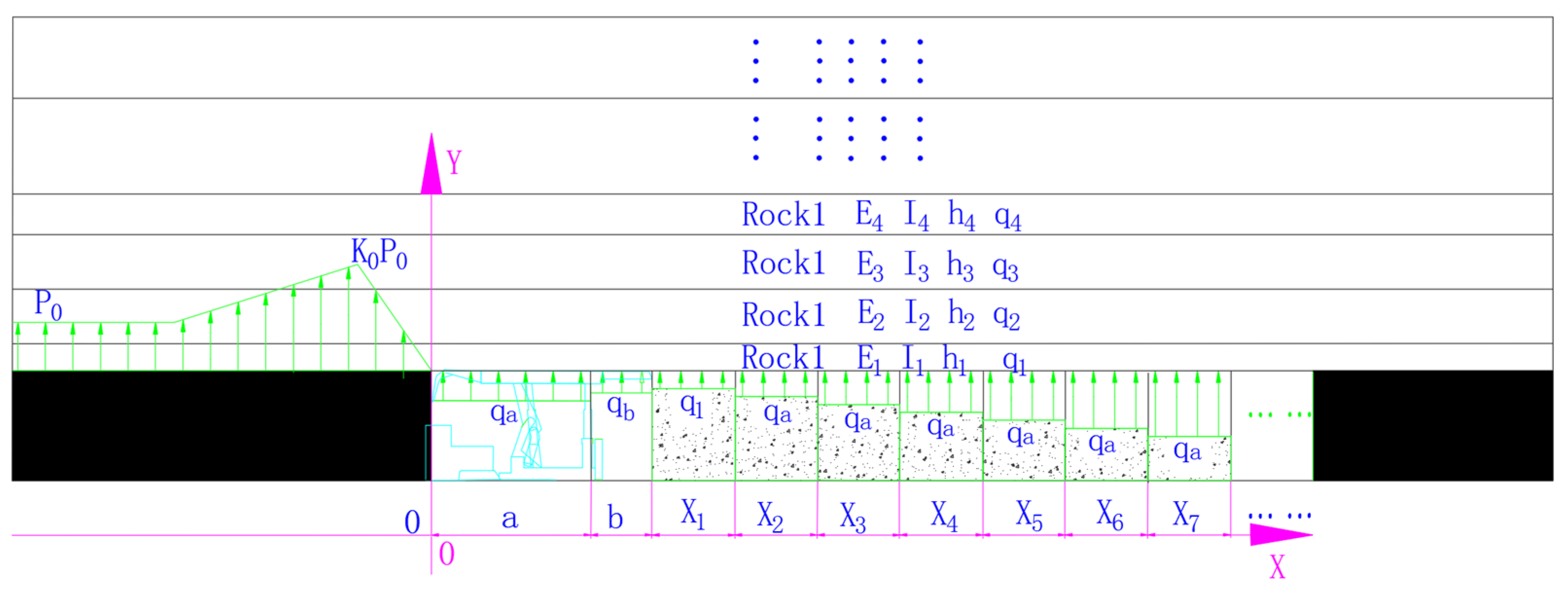
3.1. Stress Model of Paste-Filling Working Face

The rock strata above the paste-filling working face are supported by a coal wall, hydraulic support, and filling body on both sides within a short distance from the beginning of the working face advancing during longwall paste-filling mining. The rock strata above the filling working face are jointly supported by supports, the supporting system formed by the filling body, and coal in front of the coal wall with the advanced working face when it is mined to a certain distance. The practice is to form a stably stressed environment. The main roof of the working face does not fail, which forms continuous rock beams with an infinite elastic foundation before and after the coal wall.
The stress model of the filling working surface is simplified (see Figure 3). One direction of the first filling body behind the filling hydraulic support is free and can be simplified as a one-way force. The second filling body is subjected to three-way compression at the beginning, and there is no limit to the compression of each filling body vertically. The amount of compression depends on the pressure of the overlying strata and the strength parameter of filling. The filling body decreases successively from left to right in terms of transverse strain until the transverse displacement is 0 and the horizontal transverse strain is the only direction. That is, the overall direction is opposite along the X-axis.

3.2. Analysis of the Roof Subsidence Law of the Filled Working Face

W. Budrake of Poland first studied the problems of roof bending, subsidence, and stress distribution in filling mining. He also theoretically proved the correctness of the pressure wave theory. A. Sauustovich analyzed the roof deflection and the vertically stressed distribution before and after the filled mining working face on this basis. The strength change in the filling is not analyzed when the filling body behind the working face is discussed. Therefore, the roof deflection curve behind the working face should be determined according to the strength of the filling material. The roof deflection curve in front of the paste-filling working face should be analyzed according to A. Sauustovich’s formula.
The law of the roof subsidence curve of the paste-filling working face is composed of two parts. One is the roof subsidence at the coal wall (w1). It is only a relative quantity and does not affect the shape of the deflection curve behind the working face. The other is the stable subsidence part (w2), which is obtained by the interaction of the volume weight of the roof strata and the supporting force of supports and the filling body. This part is accumulated by each step distance during filling.
That is,
z 2 = w 1 + w 2
The roof subsidence at the coal wall (w1) is equal to the value of the roof deflection curve in front of the working face at x = 0, namely,
w 1 = p z k v β 2 α 2 p z k s
The solution of the part (w2) interacting with the volume weight of the roof strata, the supporting force of the support, and the supporting force of the filling body is as follows. The overlying strata roof on the working surface is regarded as the fixed support beam at both ends, and the pressure comes from the roof strata at the initial stage of paste filling. It is only subject to the weight of the overlying direct roof at the initial stage of mining since the roof of backfill mining does not collapse. Then, the weight is multiplied by the pressure coefficient of the upper roof against the immediate roof. The strength of the backfill body gradually increases. The span of the immediate roof increases, and the subsidence of the immediate roof increases with the advance of the working face. The subsidence curve of the roof changes with each step of the advance because the compression of the backfill body is irreversible.
The solution of the second part, w2, of the roof subsidence deflection curve behind the paste-filling working face is as follows. The total deflection of the fixed beam at both ends can be generated by the separate action of various forces at each step and superimposed on each other to obtain the deflection curve under the same coordinates. The boundary condition of the beam is that the angles generated by various forces at the left and right ends of the beam are 0. Therefore, the deflection formula of the beam can be expressed as
w 2 = n = 1 n   f x n = n = 1 n   w q r o c k + w x a + w x b + w x 1 + w x 2 + + w x n
where f ( x n ) is the deflection of roof strata at each advance step; w(qrock mass) is the deflection caused by the volume weight of the roof strata; w ( x a ) is the deflection of the roof strata in the coal mining area generated by the filling hydraulic support; and w ( x b ) is the deflection generated by the filling area of hydraulic support on the roof strata. The area has no supporting function, and the value is 0. w ( x n ) is the deflection caused by the support of each filling body on the roof strata.
(1)
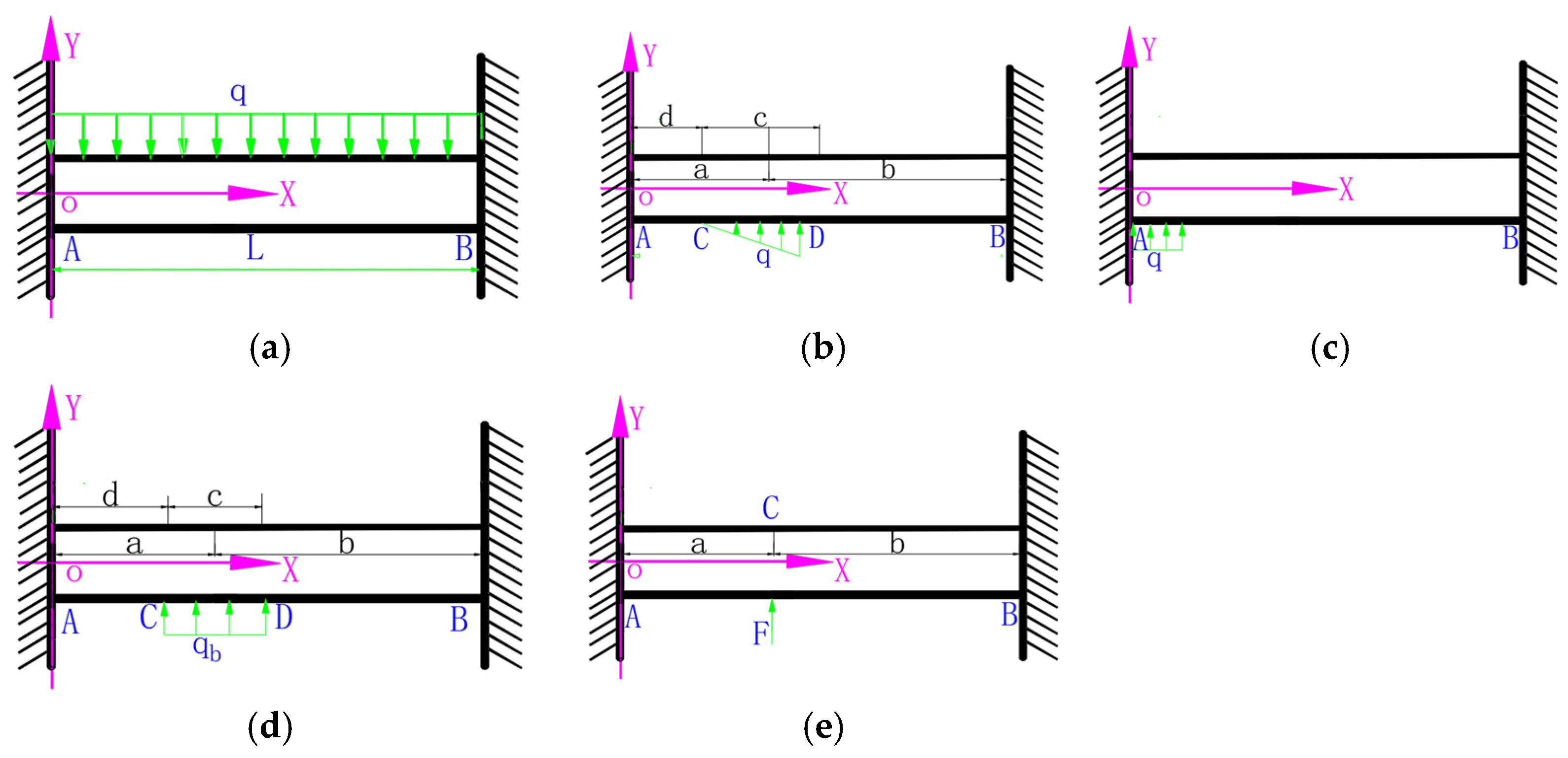
The calculation model of the deflection generated by the volume weight of the roof strata can be simplified (see Figure 4a). The rock beam bends due to its volume weight, and the deflection curve formula of the beam is obtained by the integral method, as follows:
w q ( x ) = q x 2 24 E I ( x l ) 2
Figure 4. Simplified models of roof stress.
Applsci 13 08017 g004
(2)
The supporting load of the filling hydraulic support on the roof is based on the triangular load in the filling working face. The front of the triangular load has an appropriate unsupported roof distance. Figure 4b shows the mechanical model. Actual paste-filling working face support has a supporting function, and the overlying roof no longer sinks. Errors will occur if the actual support load on the roof is used to calculate the roof deflection curve. Therefore, the equivalent supporting force of the self-weight load of the overlying strata is set in the supporting area. This is to simulate the supporting force of the support on the roof. The two can offset the influence of force relatively without changing the structural form of the beam. Figure 4c presents a mechanical model.
The mechanical deflection of the roof in the filling area can be calculated as follows:
w q a ( x ) = { 1 6 E I ( R A x 3 + 3 M A x 2 q x 4 4 ) ,   0 x a 1 6 E I [ R A x 3 + 3 M A x 2 + q a 4 ( a 3 4 a 2 x + 6 a x 2 4 x 3 ) ] ,   a < x l
(3)
The supporting force of the filling body on the roof strata is considered a uniform load. Figure 4d lists the mechanical model and a = d + 0.5c. The supporting force generated by the two ends of the beam is as follows.
R A = q c 4 l 3 ( 12 b 2 l 8 b 3 + c 2 l 2 b c 2 )
and
R B = q c R A
The mechanical deflection of the roof in section A-C is calculated as follows:
w ( x ) = q c 24 E I l 3 [ ( 12 a b 2 3 b c 2 + c 2 l ) l x 2 ( 12 b 2 l 8 b 3 + c 2 l 2 b c 2 ) x 3 ]
The mechanical deflection of the roof in section C-D is calculated as follows:
w ( x ) = q 24 E I l 3 [ ( 12 a b 2 3 b c 2 + c 2 l ) c l x 2 ( 12 b 2 l 8 b 3 + c 2 l 2 b c 2 ) c x 3 + l 3 ( x d ) 4 ]
The mechanical deflection of the roof in section D-B is calculated as follows:
w ( x ) = q c 24 E I l 3 [ ( 12 a b 2 3 b c 2 + c 2 l ) l x 2 ( 12 b 2 l 8 b 3 + c 2 l 2 b c 2 ) x 3 + l 3 ( x a ) 3 + q c 2 l 3 ( x a ) 4 ]
(4)
The model can be simplified when the paste-filling working face advances for a long distance. The supporting force of each filling body on the roof is assumed to be the concentrated force from the uniform load set previously. Figure 4e presents the force model. The equation of the beam deflection curve obtained by the integral method is as follows:
w q ( x ) = { q c b 2 x 2 6 E I l 3 ( 3 a l l x 2 a x ) ,   0 x a q c a 2 ( l x ) 2 6 E I l 3 ( l x + 2 b x a l ) ,   a < x l
The deflection formula behind the paste-filling working face can be obtained through the calculation of the mechanical formula group. The deflection formula of the roof behind the filling working face is a quadric equation with one variable after analyzing the results of each calculation formula. That is,
z = α 4 x 4 + α 3 x 3 + α 2 x 2 + α 1 x + β
Then,
z 1 = p z k v β 2 α 2 p z k s q x 2 24 E I ( x l ) 2 E 1 c q ( 4 c 7 20 c 6 l + 32 c 5 l 2 1 7 c 4 l 3 8 c 2 l 5 + 1 6 c l 6 16 l 7 ) 144 E I l 3 [ 128 E I l 3 2 E 1 c c 3 ( 2 l c ) 3 ] × { x 2 ( c 2 l ) 2 ( 2 cx 3 c l + 2 l x ) ,   0 x 0.5 c c 2 ( l x ) 2 ( c l + 2 c x 6 l x ) ,   0.5 c < x l + 1 24 E I l 3 q ( l x ) { ( b 4 l 2 + b 4 l x 2 b 4 x 2 3 b 3 l 3 + 4 b 3 l x 2 + 2 b 2 l 4 2 b 2 l 3 x + 2 b l 5 4 b l 4 x + 2 b l 3 x 2 4 l 6 + 12 l 5 x 12 l 4 x 2 + 4 l 3 x 3 ; 0 x a ( l x ) ( b 4 l + 2 b 4 x 4 b 3 l 2 4 b 3 l x + 6 b 2 l 3 4 b l 4 + 4 b l 3 x l 5 + 2 l 4 x l 3 x 2 ,   a < x l
where p z is the overlying strata roof pressure; k v is the coefficient of the coal foundation; k s is the foundation coefficient of the filling body; q is the direct load of the roof; l is the distance of the working face advancing; b is the supporting scope of support; and a is the length of the filling body.
Coefficients in the formula are affected by the volume weight of the immediate roof, the elastic modulus and moment of inertia of the roof, the advancing length of the working face, filling step distance, the elastic modulus, and Poisson’s ratio of each filling body, and the foundation coefficients of the coal body and filling body.
Through the calculation of the formula mentioned above by incorporating various filling parameters, it was determined that the primary factors influencing the subsidence of the roof in the filling working face are the lithology parameters of the roof, the filling step distance of the working face, the strength of the filling material, the filling rate, and other related parameters. These factors collectively contribute to the overall behavior of roof subsidence in the filling mining process. The specific values and interactions of these parameters have a significant impact on the extent and characteristics of roof subsidence in the mining operation.

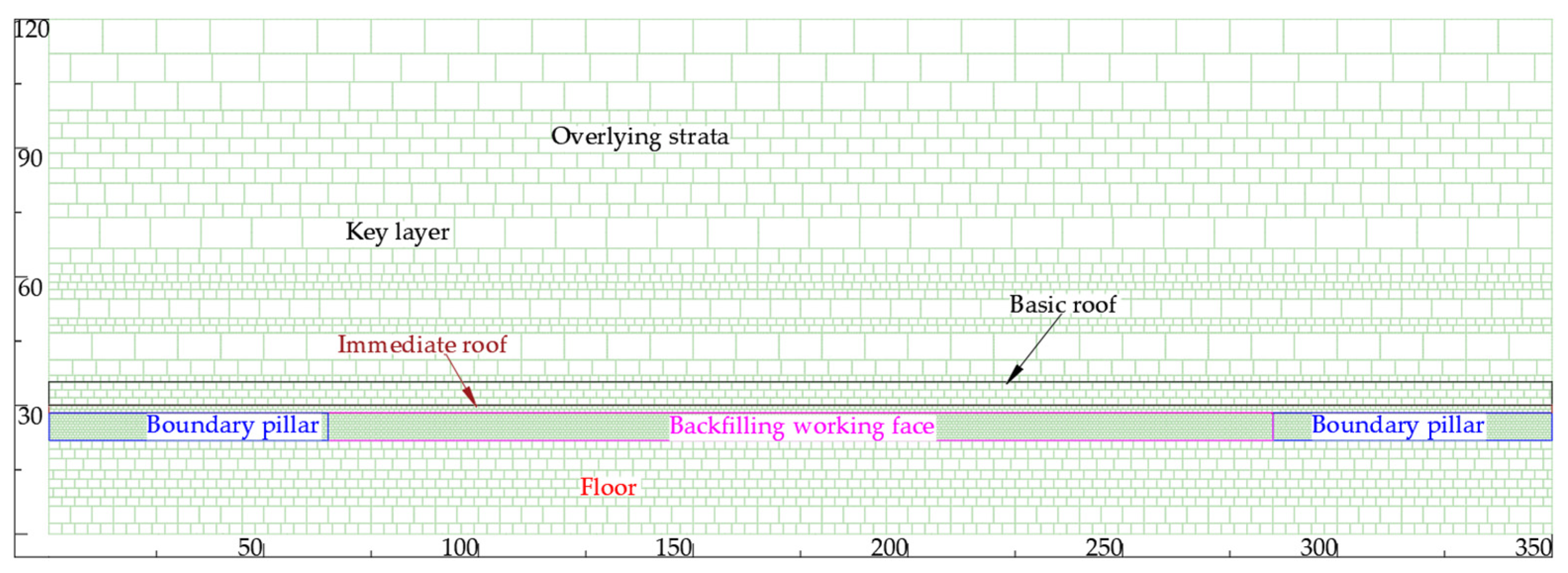
4. Numerical Simulation of Overlying Strata Movement in the Filled Working Face

UDEC7.0 simulation software was used to simulate the stress and strain law of the surrounding rocks and the overlying strata subsidence control level during longwall paste-filling mining, and is based on the longwall filling mining of Gaohe Energy. A simulation width of 350 m was established, and a boundary of 60 m was set on both sides according to the filling mining conditions. The height of the model was 120 m, and the roof of the coal seam was 90 m. The remaining 350 m of overlying strata were simulated by applying a uniform load according to 8 MPa, and 230 m of simulated coal in the middle was mined at a mining height of 3.5 m. Mining was operated when the filling rate was 94%. Figure 5 lists the model.

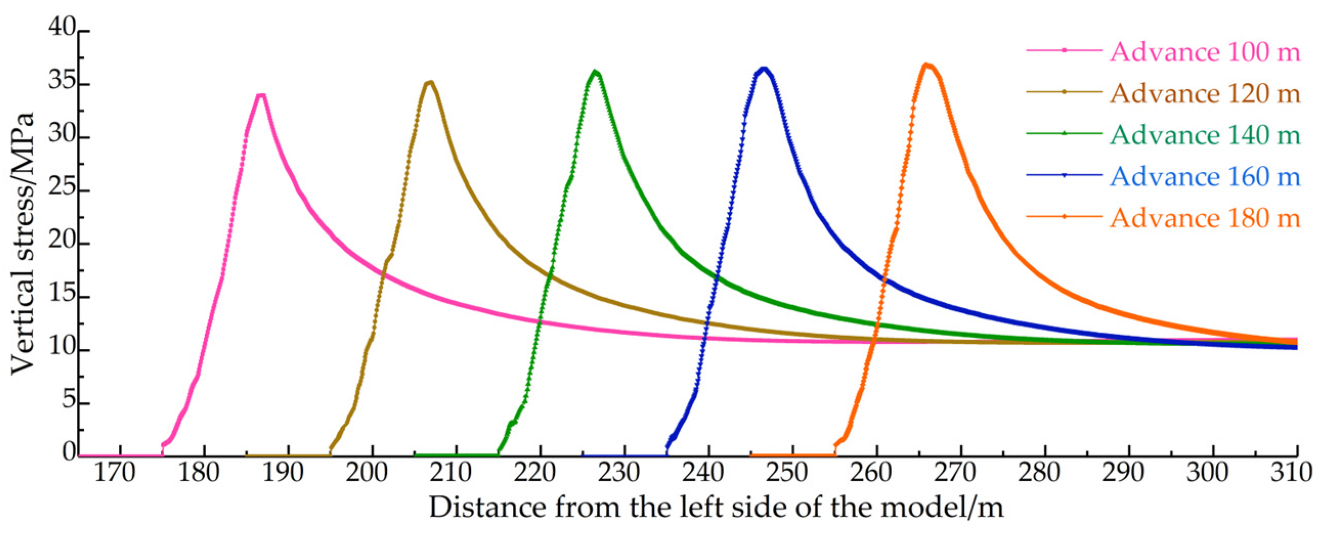
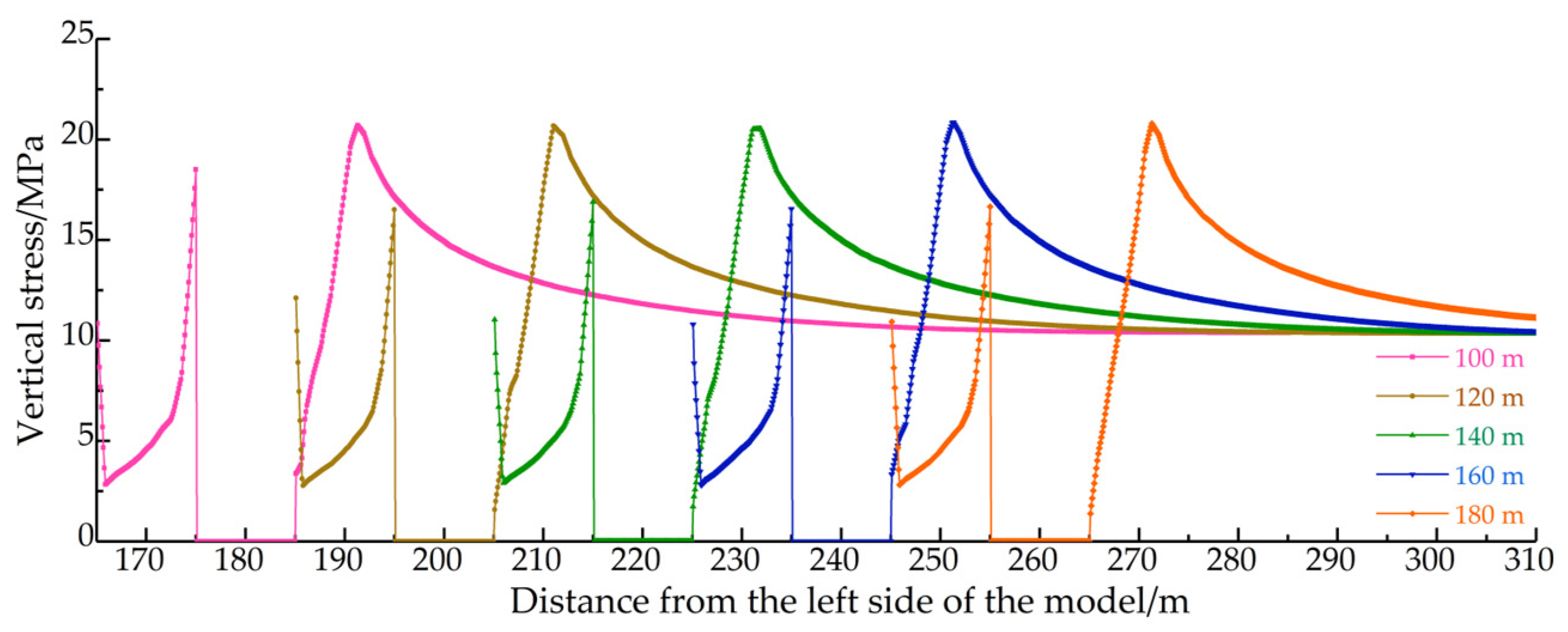
4.1. Research of Stress Distribution Law of Filling Working Face

The working face advances 100, 120, 140, 160, and 180 m, respectively, through simulation according to the collapsed method and filling method. Figure 6 and Figure 7 show the roof stress distribution law of the collapsed working face and that of the filled working face, respectively. The maximum stress of the overlying strata on the collapsed surface is 37.5 MPa; the stress of normal overlying strata is 11 MPa; the stress coefficient reaches 3.4; the maximum stress of overlying strata on the filled surface is 20 MPa; and the stress coefficient reaches 1.8. Stress concentration in backfill mining is less than that in collapsed mining, according to the simulation. The elastic–plastic failure range of surrounding rocks of these two mining methods is analyzed. Figure 8 and Figure 9 show the distribution of the plastic zone. The failure range of surrounding rocks in expansion mining reaches 5–6 times the mining height due to the different effects of concentrated stress, while that in filling mining is only 1–2 times the mining height.

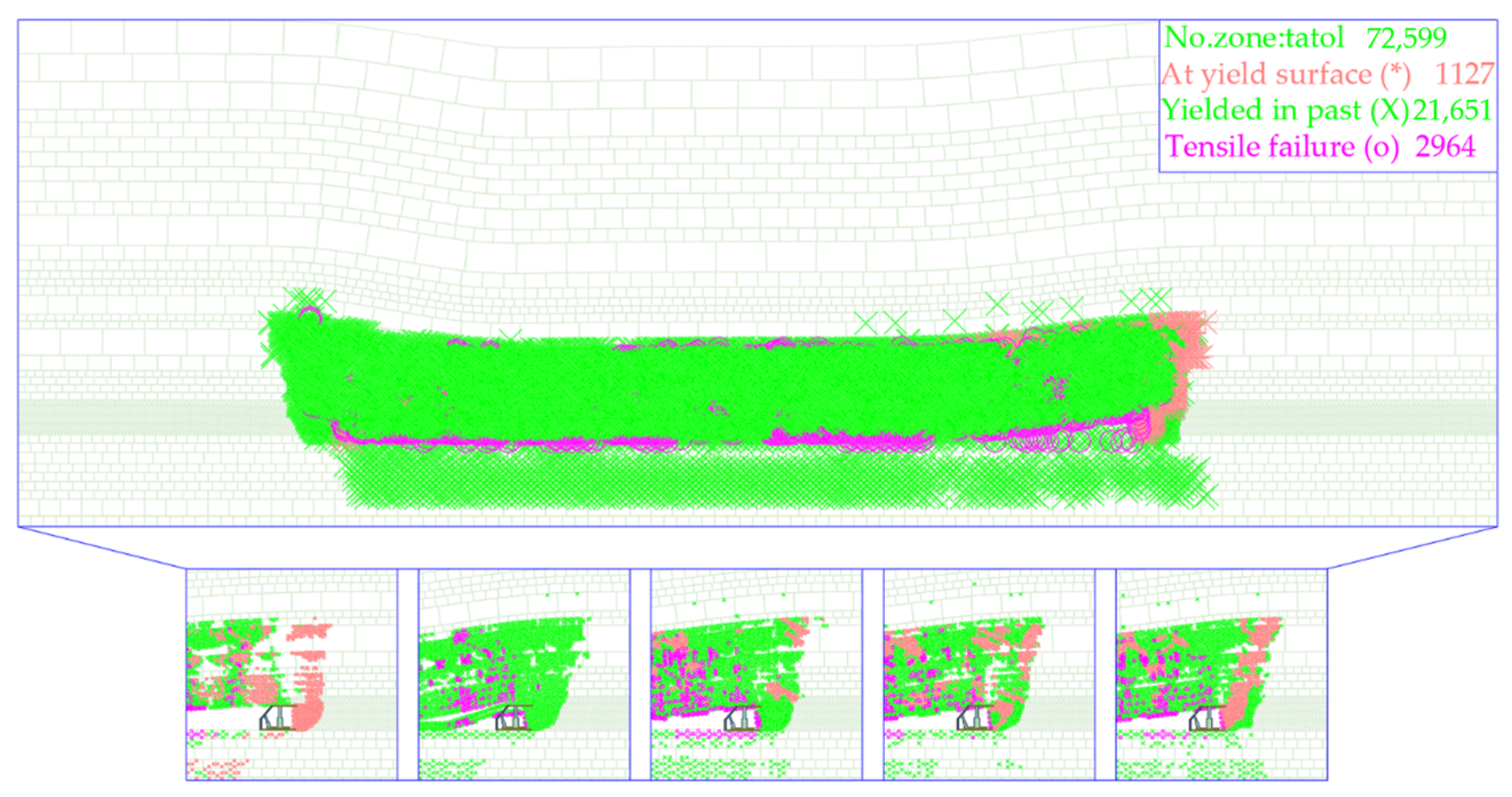
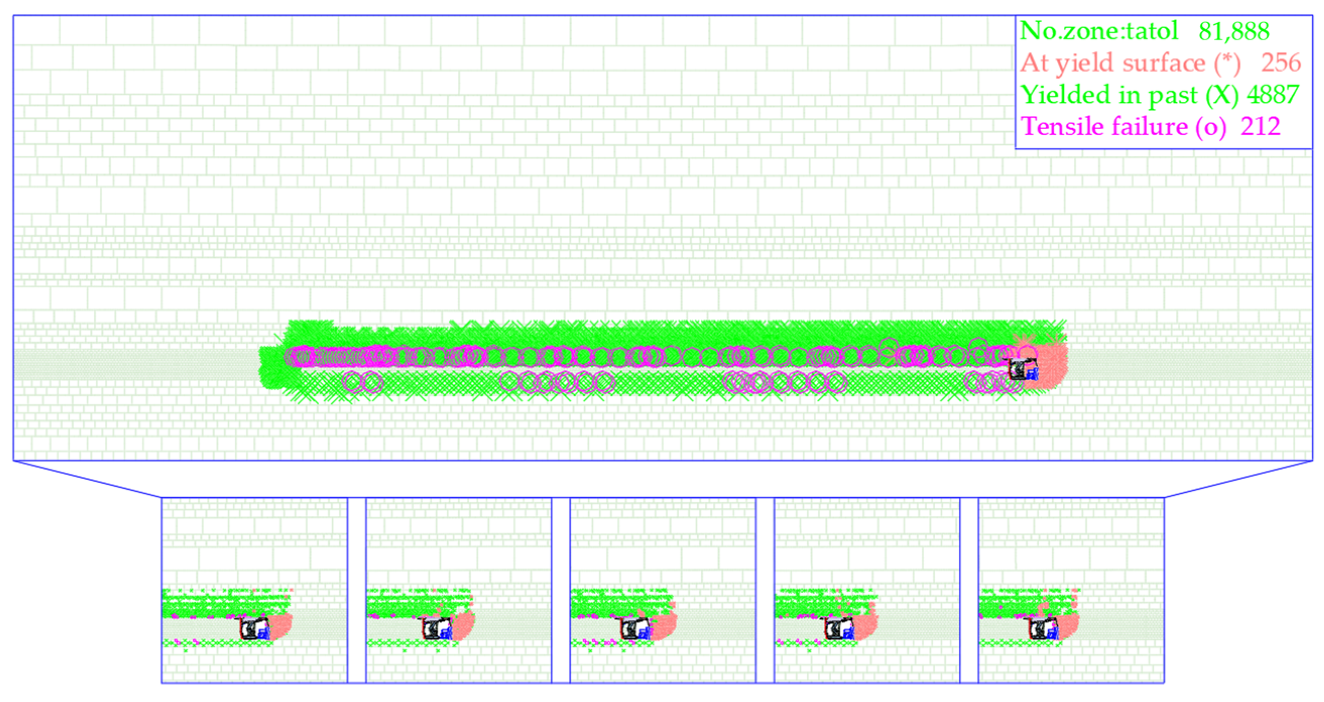
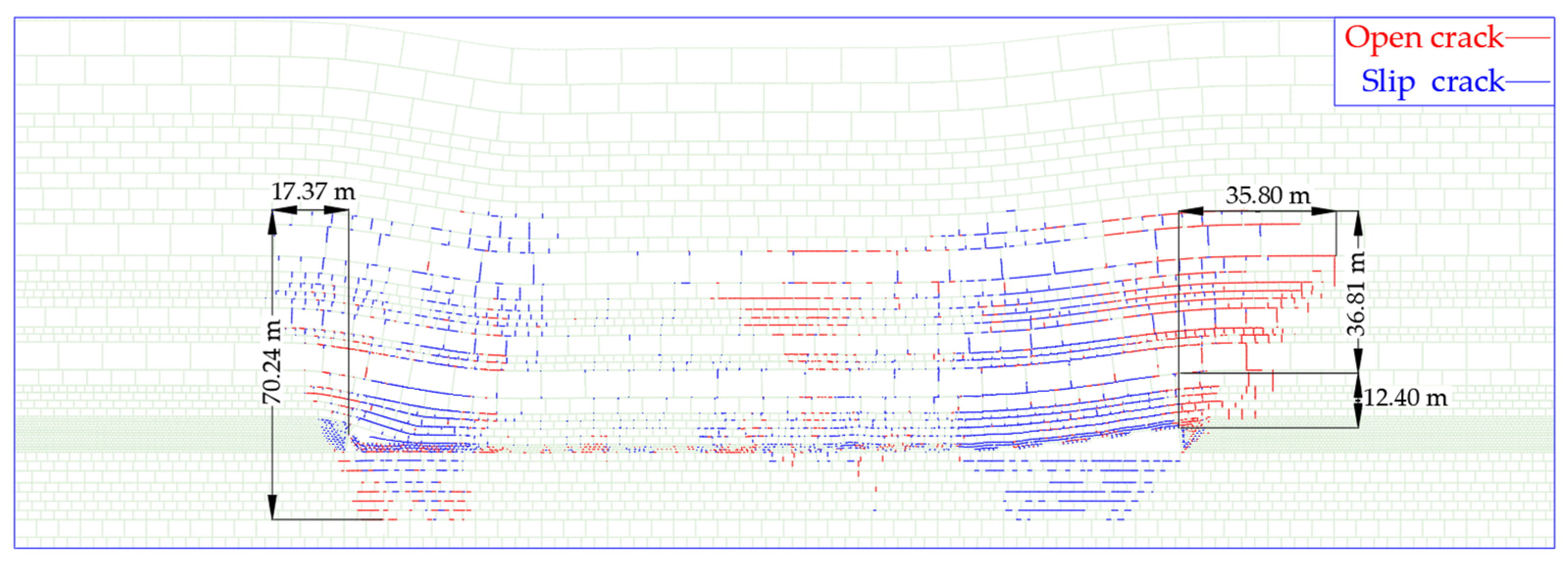
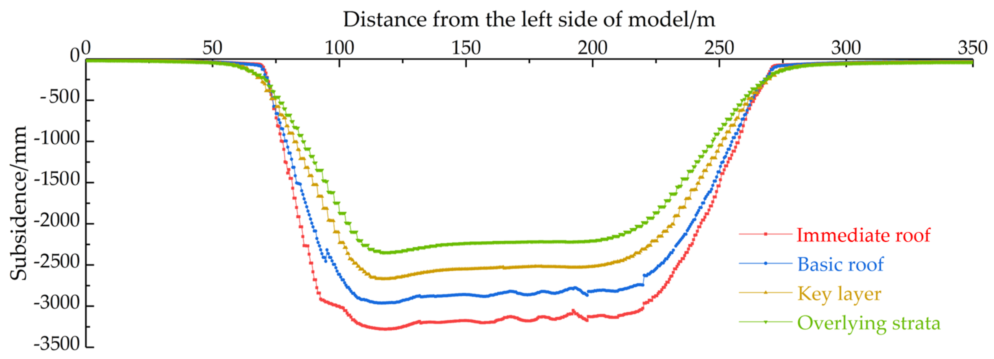
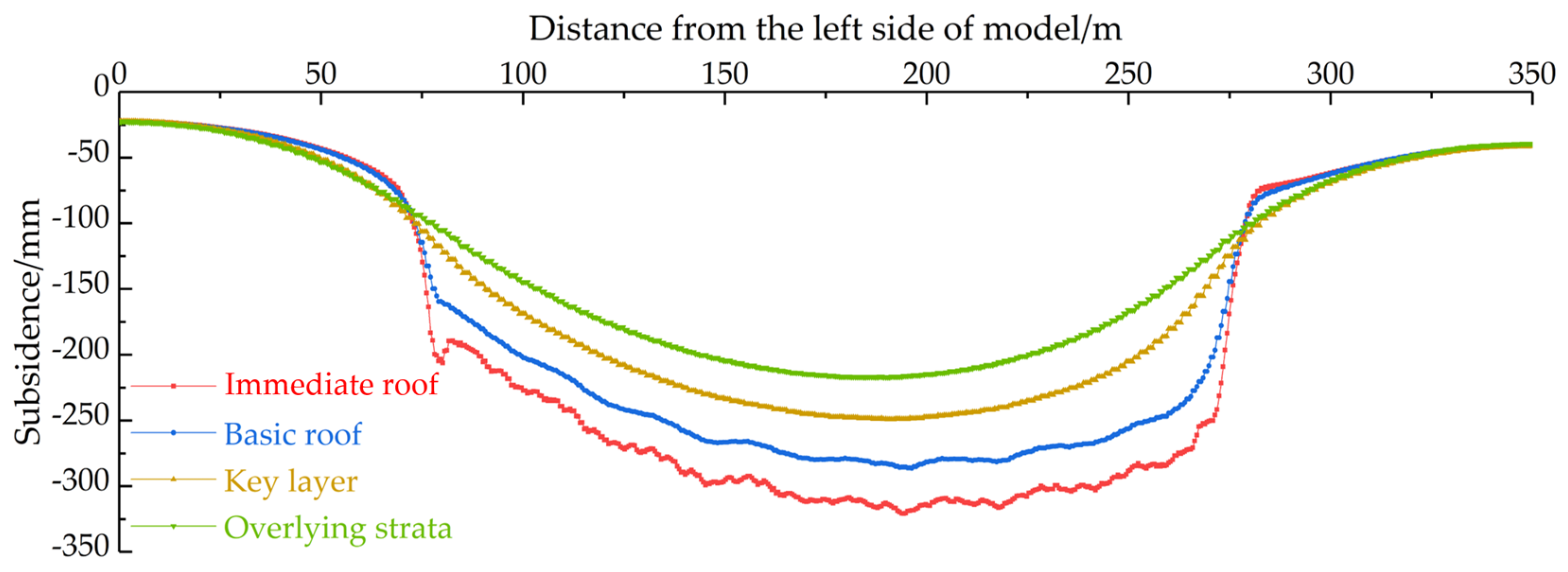
4.2. Research on the Movement Law of Overburden Rock in Filling Face

The collapsed roof fracture and failure appear with the advance of the working face. The failure range of rock movement is large, and the falling zone, stratification zone, and bending subsidence zone appear (see Figure 10 and Figure 11 for the overlying deformation of the collapsed working face). The height of the falling zone in the simulation is 12.4 m; the height of the separation zone is 36.1 m; the maximum earth surface subsidence is 2250 mm; and the subsidence coefficient is 0.64. The filling body supports the overlying strata in time with the advanced working face. The roof does not fall, and only partial separation appears near the working face with a maximum height of 40.87 m.
Figure 12 and Figure 13 show the overlying strata deformation of the filled working face without obvious surrounding rock failure.
In the case of filling mining, during the advancement of the working face, open cracks primarily occur above the working face, exhibiting a characteristic “sail-shaped” pattern. The height of crack development above the coal seam reaches 30.5 m, while the advanced working face itself has a development height of 11.89 m. Upon extraction of the coal seam, it is crucial to promptly replace the filling material. The filling material should be placed in direct contact with the coal seam without any fractures, allowing for bending and sinking. Once in contact with the filling material, the movement of the overlying rock is constrained, and the cracks formed by the overlying rock on the working face undergo re-compaction. Consequently, the development of fractures in filling mining can be divided into several stages: advanced development of fractures, re-compaction of fractures, and stable maintenance of fractures. Notably, the advanced fractures exhibit a distinctive “sail-shaped” progression, while the re-compaction region of fractures is located above the back of the cutting hole. The fractures occurring behind the working face are limited to the basic top rock layer (see Figure 12).
Figure 13 illustrates the movement curve of the overlying rock following backfilling mining. In the case of filling mining, the equivalent mining height is 320 mm, and the direct roof experiences a maximum subsidence of 315 mm. The curved and sinking direct roof plays a significant role in controlling the movement of the underlying basic roof rock layer. Importantly, the direct roof only sinks without any fragmentation or expansion occurring. The maximum subsidence observed in the basic roof is 282 mm, while the key layer and the overlying rock of the key layer experience maximum subsidence values of 243 mm and 226 mm, respectively. The maximum surface subsidence measures 220 mm, resulting in a subsidence coefficient of 0.063. Notably, this subsidence coefficient is approximately 1/10 of that observed in caving mining, indicating a significantly reduced level of subsidence in filling mining.

5. Analysis of the Main Influencing Factors of Overlying Rock Movement in Filling Working Face

According to the mechanical research in Section 2, the filled working face forms an overlying strata structure with coal, filling support, and a filling body. The immediate roof of the working face does not collapse and break, and the overlying strata are in curved subsidence. The main factors that affect the roof subsidence of the filling face are the filling rate, filling step distance, and the compression amount of the filling body. This chapter further studies the above theoretical results through on-site measurements.

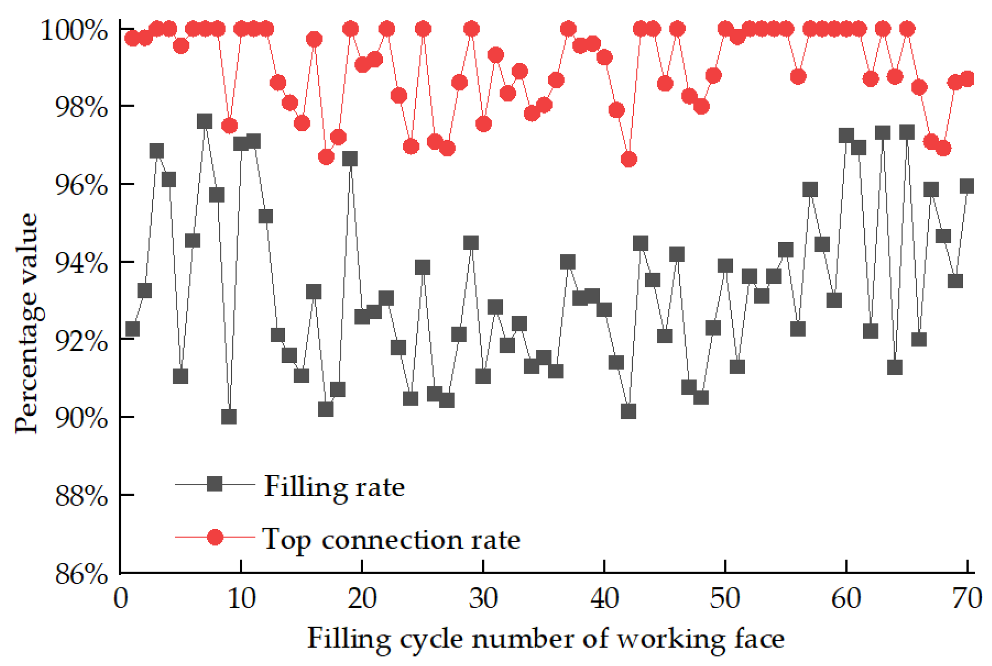
5.1. Analysis of the Filling Rate

The area to be filled should be filled by filling pipe after isolating the filling area on the working face. The roof of the area to be filled sinks with the advanced working face. Therefore, the filling rate is above 98% according to the specific value between the actual filling amount and the volume of the area to be filled, and some areas are not filled due to insufficient slurry. The specific value between the actual filling amount and the coal mining space is called the filling rate. The average filling rate reaches over 94% through 70 filling data analyses (see Figure 14).
As depicted in Figure 15, the roof of the underground working face remains intact, and there is excellent cohesion between the filling material and the top surface. The integrity of the working face’s roof improves as the filling rate increases, leading to enhanced control over rock displacement.

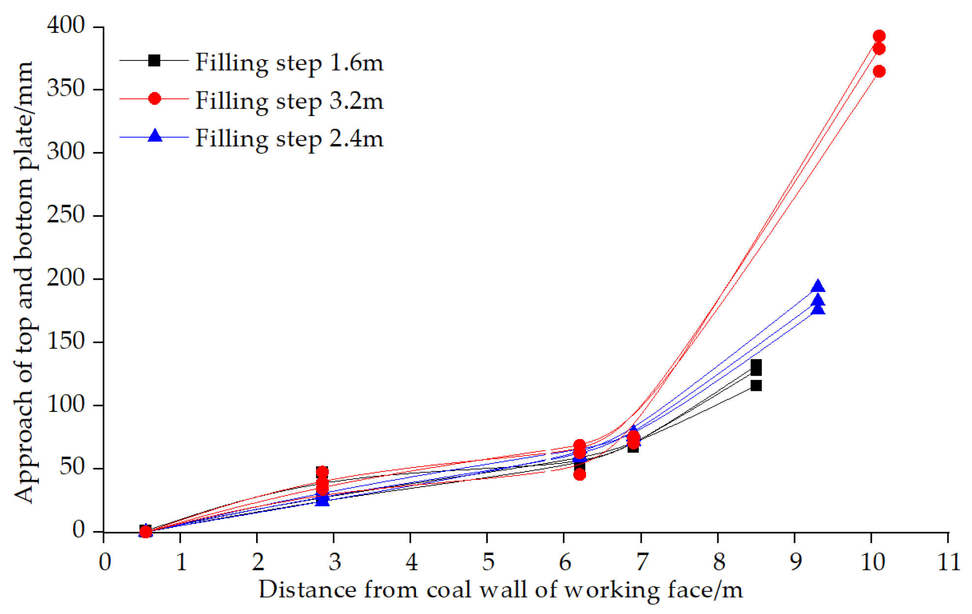
5.2. Analysis of the Filling Step Distance

Multiple sets of data were applied to the working face to measure roof subsidence and master the convergence law of the roof and floor of the filled working face. In addition, the relation between roof subsidence and filling step distance is observed (see Figure 16), and that between roof subsidence and working face exposure time is shown (see Figure 17). The roof of the filled working face does not break but is in curved subsidence according to actual observation data, which is related to the exposure distance and time of the filled working face.
Roof subsidence is subtle, and overall subsidence is about 50 mm in the range of filling support (0–6 m). Subsidence increases when the roof reaches the unsupported area to be filled. Filling step distances of 1.6, 2.4, and 3.2 m were measured in industrial practice. The roof subsidence increases exponentially with the increased filling step distance. Therefore, a shorter filling step distance is preferable during controlling overlying strata movement. However, the short filling step distance has a certain impact on filling isolation. Therefore, the filling step distance of 2.4 m was selected according to the filling mining conditions of Gaohe.
The relation between roof subsidence and exposure time is observed when the filling step distance is 2.4 m. Roof subsidence increased with longer isolation time. Therefore, working face roof subsidence increases first and then becomes stable. The filling body plays a certain supporting role, and then roof subsidence is restrained mainly because the roof sinks to a certain deflection. The higher the efficiency of the filled working face, the better the roof control from the analysis of the overlying strata movement law. The normal isolation time of the filled working face is 16 h, and roof subsidence is about 180 mm.

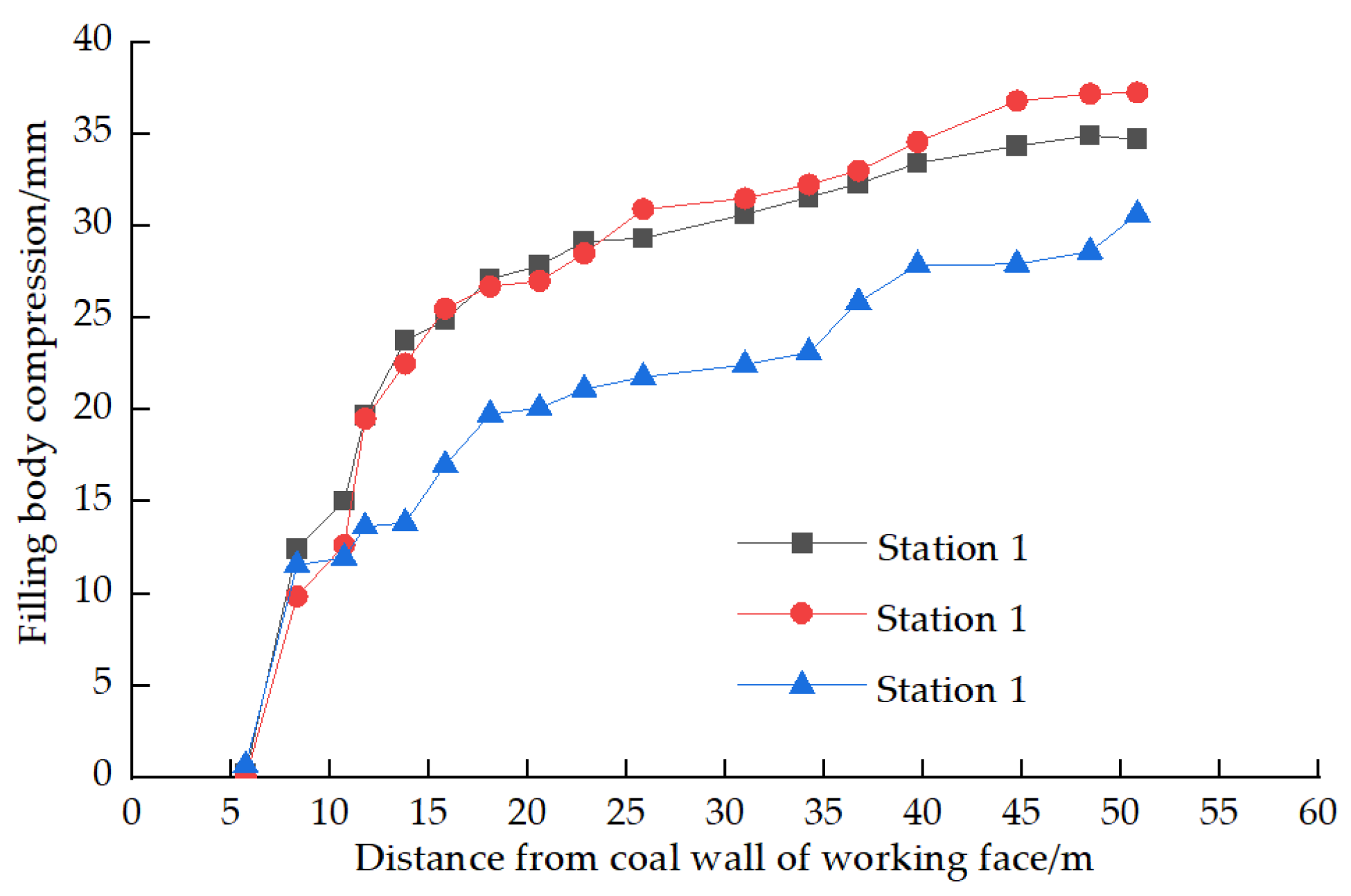
5.3. Analysis of the Compression Amount of the Filling Body

A rod-style displacement meter is set in the filling body of the filled working face. The compression amount of the filling body is reflected through the displacement meter with the advance of the work (see Figure 18). The partial compression amount of the filling body is about 35 mm. The compression amount is small, and the overall compression rate is about 1% due to the roof condition being good. A total of 80% of the deformation of the filling body is completed within 20 m after filling.

6. Earth Surface Subsidence Law in Filling Mining

6.1. Actual Measurement of Earth Surface Subsidence

Researchers arranged two measuring lines on the earth surface of the Gaohe Energy E1302 paste-filling working face, with 23 measuring points along the working strike and 21 measuring points on the working face inclination. The mining of the working face was completed on 15 September 2021, and a total of 11 observations were made by July 2022 (see Figure 19 and Figure 20 for the subsidence curve chart of the earth surface strike and inclination, respectively).
The subsidence and basin range of the main section of the strike extends forward with the continuous advancement of the working face. By June 2020, it has advanced 21 m, and the earth surface has sunken 10 mm. The subsidence amplitude and basin range gradually increased with the advancement of the working face after the starting distance. They increased to the maximum by the end of the advanced working face. The width–depth ratios of strike mining and inclined mining are 1.12 and 0.57, respectively, and they belong to insufficient mining under strike. Earth surface subsidence near the starting point of the survey line is relatively large due to the previous mining on the E1302 working face. Fixed point A17 is the maximum subsidence point, and the subsidence value is 215 mm. The whole curve conforms to the law of the general subsidence curve.
The slope curve represents the change law of the inclination in the earth surface moving basin according to the actual data measurement. The north–south surveyed lines A12–13 of the observation station have the largest inclination, with an inclined value of 1.2 mm/m, and the east–west surveyed line B has the maximum inclination of 1.4 mm/m. The maximum deformation is −1.3–1.4 mm/m, located in regions B10–11, which is greatly affected by the original collapsed goaf. The collapsed method affects the actual situation where level value B20 above the filled mining surface is close to the filling surface, namely, −0.7 mm/m. A11–12 have a maximum deflection of −0.03 mm/m2. The regional deformation of land surface buildings is within 50% of the Grade I deformation stipulated in the code of coal mining under buildings [24], so the buildings can be well protected.

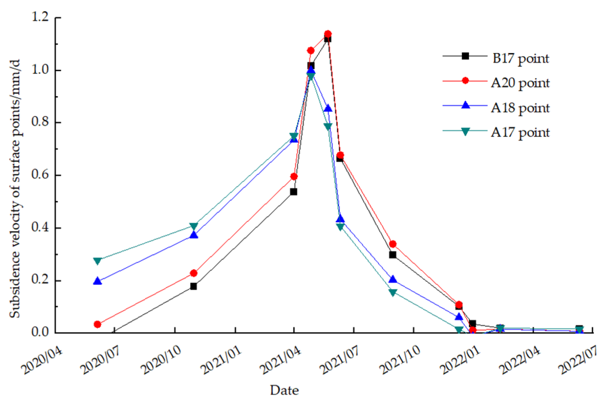
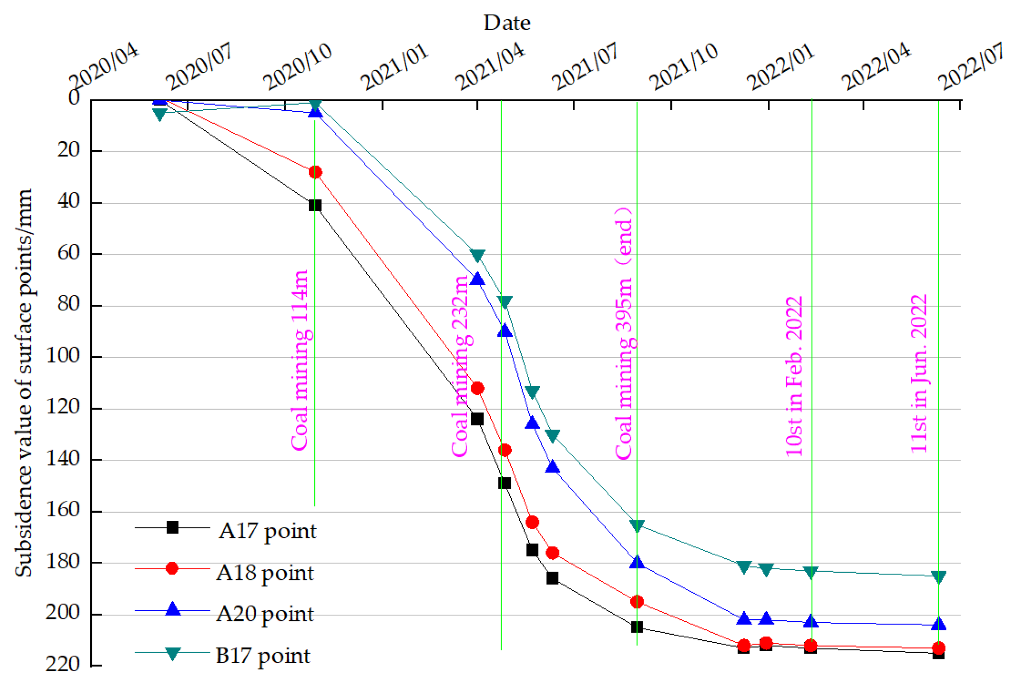
6.2. Law of Earth Surface Subsidence

The relation between subsidence amount and velocity of the main survey points above the working face and time was analyzed (see Figure 21 and Figure 22). The subsidence of the earth surface survey point appears rapid at first and then becomes steady with the advancement of the working face. The maximum subsidence velocity of the earth surface is 1.15 mm/d, which does not show the active phase of the earth surface movement (with the subsidence velocity of the survey point greater than 1.7 mm/d) presented by collapsed mining. Instead, overall subsidence is mild. The maximum subsidence velocity of the earth surface decreases to less than 0.4 mm/d after the mining of the working face. The amount of movement in the recent half year is about 20 mm. The error of the three recent observations did not increase significantly, and it has shown a stable state. The earth surface subsidence of collapsed mining can be divided into the initial period, activity period, and declining period. The stabilization time for Gaohe after normal collapsed surface mining is as long as 3 years. Earth surface subsidence only appears in the declining period and can reach a stable state half a year after mining, according to the actual measurement.
The roof does not collapse due to the supporting of the filling body during the paste-filling mining [25]. The main roof only moves slowly with the immediate roof, and the overall pressure of the paste filling is not significant. There is no significant first weighing or periodic weighing, and earth surface subsidence is relatively mild. There is no activity period of earth surface movement in collapsed mining, and the time of earth surface stabilization is short.

7. Conclusions

This paper investigates the primary factors influencing overburden movement in the E1302 paste-filling working face at Gaohe Mine. It employs mathematical analysis to examine the movement characteristics of overburden and ground deformation patterns in both caving mining and paste-filling mining. Numerical simulations are conducted to compare these characteristics, followed by field measurements to validate and analyze the mathematical analysis and numerical simulation results. Based on these investigations, the following conclusions are drawn:
(1)
The deflection formula for the roof behind the paste-filling face can be represented by a unified quartic equation. The significant factors that influence the substantial subsidence of the roof in the filling face include the step distance of the face during filling, the strength of the filling material, the filling rate, and other associated parameters;
(2)
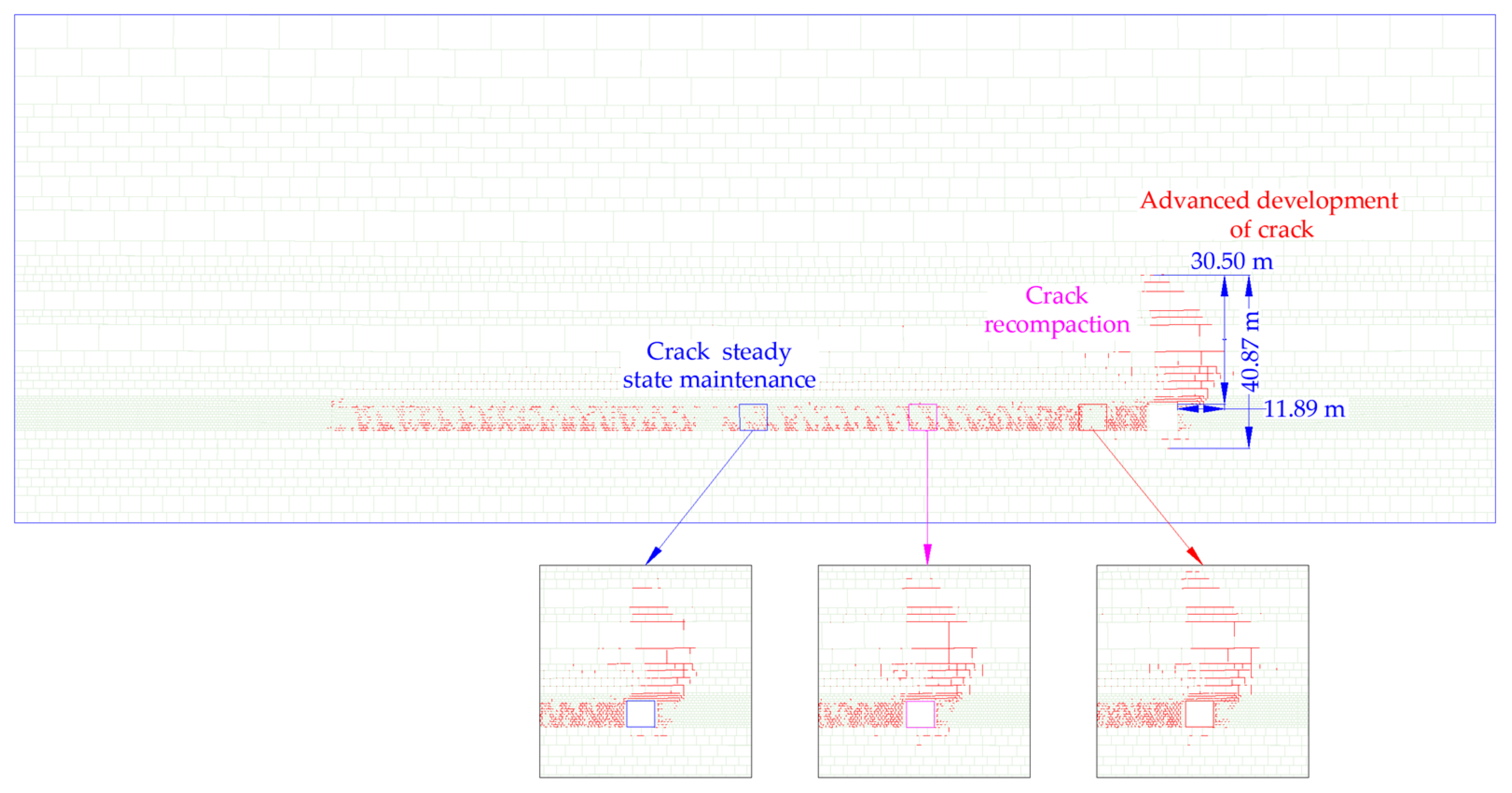
Numerical simulation studies have revealed significant differences between filling mining and traditional caving mining in terms of stress concentration, stress influence range, and overlying rock deformation. Filling mining exhibits a considerably lower degree of stress concentration in the surrounding rock, a reduced range of stress influence, and gentler deformation of the overlying rock compared to caving mining. The subsidence coefficient in filling mining is approximately one-tenth of that in caving mining. The development of cracks in filling mining can be categorized into three stages: initial crack formation, subsequent compaction of cracks, and stable maintenance of cracks. The initial crack development follows a “sail-shaped” progression. The compaction of cracks occurs predominantly above the back of the cutting hole, while cracks behind the working face are limited to the uppermost rock layer;
(3)
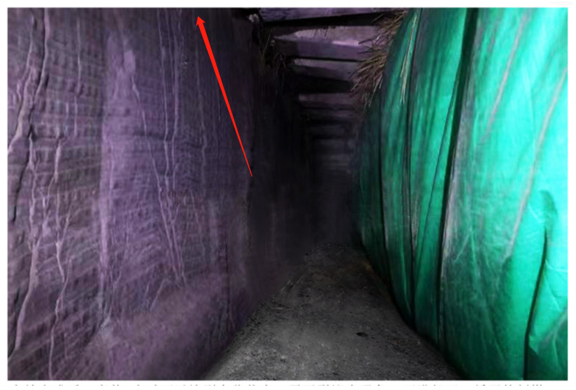
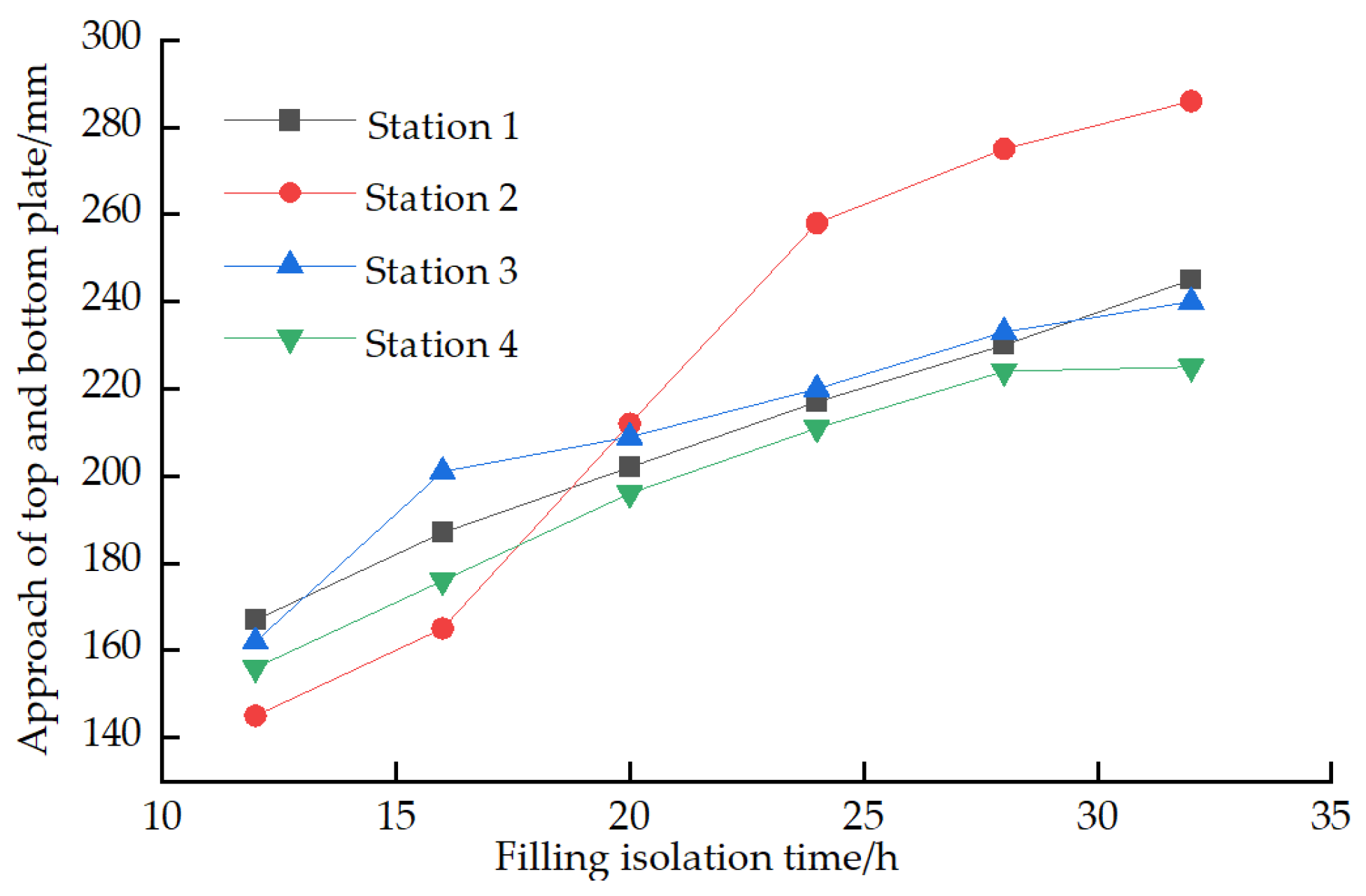
Based on on-site measurements, it was observed that the filling rate of the longwall fully mechanized mining paste filling had exceeded 94%. In this high filling rate, the top plate of the filling working face remains intact and exhibits a bent and sunken state. The subsidence of the roof demonstrates an exponential increase as the filling step distance increases. Additionally, it follows a pattern of initial increase followed by regional stability as the empty roof time progresses. Notably, approximately 80% of the deformation of the filling material occurs within a 20 m range immediately after the filling process;
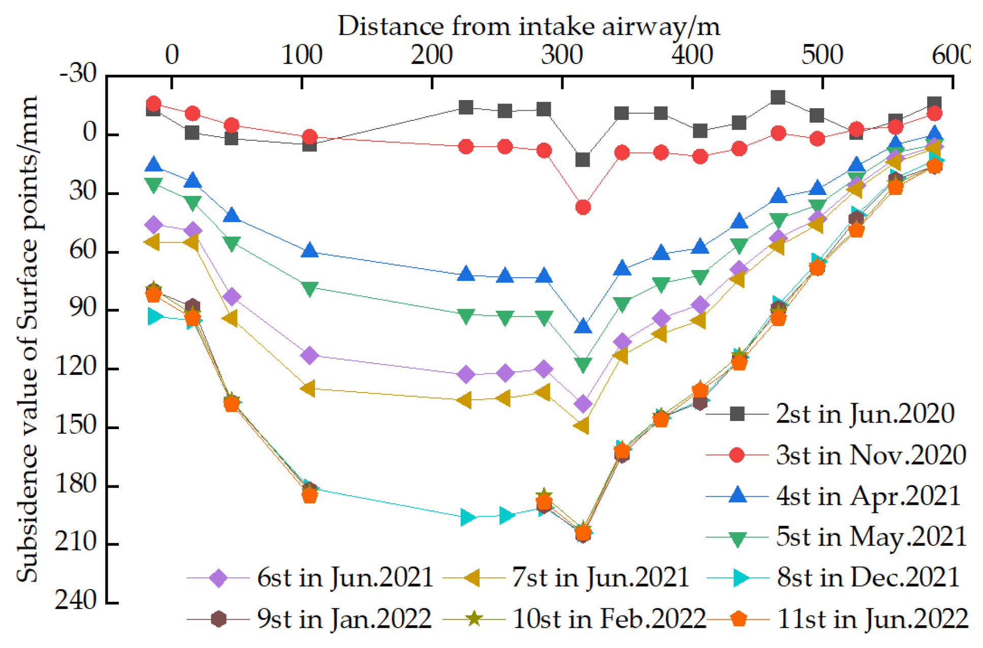
(4)
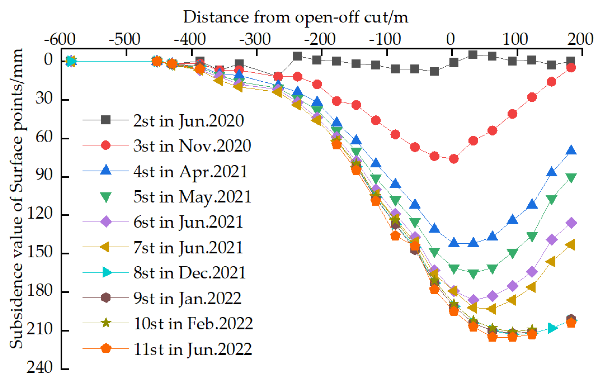
Through field measurements and analysis of surface subsidence, it was observed that the stability period of the overlying rock in paste-filling mining is considerably shorter compared to caving mining. The movement of the overlying rock is relatively gentle, without an active period of surface movement. Approximately six months after filling, the overlying rock reaches a state of stability, with a subsidence coefficient of 0.065. The maximum surface subsidence measures 215 mm, the maximum inclined deformation is 1.4 mm/m, the horizontal deformation ranges from −0.7 mm/m to 0.7 mm/m, and the maximum curvature ranges from −0.03 mm/m2 to 0.03 mm/m2. The deformation of surface buildings remains within 50% of the allowable value for Class I damage, indicating that the control of surface subsidence through paste-filling mining \ achieved favorable outcomes. These research findings serve as an effective theoretical foundation and research direction for predicting overburden movement and surface subsidence in paste-filling operations. Moreover, they contribute to the comprehensive application of paste filling in mines across China, offering valuable guidance for the environmentally friendly construction of mining operations.

Author Contributions

Conceptualization, G.S. and Z.L. methodology, L.H.; software, K.D. validation, G.S. formal analysis, K.D.; writing—original draft preparation, G.S.; writing—review and editing, Y.Z. and G.S. data curation, K.D. All authors have read and agreed to the published version of the manuscript.

Funding

The work was funded by the Key Project of Joint Funds of the National Natural Science Foundation of China (grant number U1903209) and the Key coal-based scientific and technological research projects in Shanxi Province in 2014 (grant number MJ2014-12).

Institutional Review Board Statement

Not applicable.

Informed Consent Statement

Not applicable.

Data Availability Statement

The data that support the findings of this study are available on request from the corresponding author. The data are not publicly available due to privacy or ethical restrictions.

Acknowledgments

The authors would like to thank the engineering technicians at the Gaohe Coal Mine for their enthusiastic assistance and suggestions.

Conflicts of Interest

The authors declare no conflict of interest.

References

  1. Niu, J.; Zhang, X.J.; Han, K. Design of Mining Three-UnderPressure Coal and Optimization of Numerical Simulation in Baivuan Mine. Min. Res. Dev. 2022, 42, 13–19. [Google Scholar]
  2. Xiao, J.J.; Li, S.; Yang, X.G. Study on Technology of Coal Mining under Building Replacing by Original Gangue. Coal Technol. 2022, 41, 12–16. [Google Scholar]
  3. Qian, M.G. On sustainable coal mining in China. J. China Coal Soc. 2010, 35, 529–534. [Google Scholar]
  4. Wang, J.C.; Liu, F.; Wang, L. Sustainable coal mining and mining sciences. J. China Coal Soc. 2016, 41, 2651–2660. [Google Scholar]
  5. Sun, X.K. Present situation and prospect of green backfill mining in mines. Coal Sci. Technol. 2020, 48, 48–55. [Google Scholar]
  6. Miao, X.X.; Zhang, J.X.; Guo, G.L. Study on waste-filling method and technology in fully-mechanized coal mining. J. China Coal Soc. 2010, 35, 1–6. [Google Scholar]
  7. Miao, X.X.; Ju, F.; Huang, Y.L. New development and prospect of backfilling mining theory and technology. J. China Univ. Min. Technol. 2015, 44, 391–399, 429. [Google Scholar]
  8. Feng, G.M.; Jia, K.J.; Shang, B.B. Application and prospect of super-high-water packing material in mining engineering. Coal Sci. Technol. 2015, 43, 5–9. [Google Scholar]
  9. Qian, M.G.; Xu, J.L.; Miao, X.X. Green Technique in Coal Mining. J. China Univ. Min. Technol. 2003, 32, 343–348. [Google Scholar]
  10. Sun, X.K. Research on paste backfilling mining technology of coal mining under buildings, water bodies and railways. Coal Sci. Technol. 2021, 49, 218–224. [Google Scholar]
  11. Tian, M.F. Application and Development of Mining Engineering Filling Technology. West. Resour. 2022, 3, 101–103. [Google Scholar]
  12. Liu, J.G.; Wang, H.Q.; Zhao, J.W. Review and prospect of development of solid backfill technology in coal mine. Coal Sci. Technol. 2020, 48, 27–38. [Google Scholar]
  13. Zhou, H.Q.; Hou, C.J.; Sun, X.K. Solid Waste Paste Filling for None-Village-Relocation Coal Mining. J. China Univ. Min. Technol. 2004, 33, 154–158. [Google Scholar]
  14. Chen, S.J.; Guo, W.J.; Zhou, H. Structure model and movement law of overburden during strip pillar mining backfill with cream-body. J. China Coal Soc. 2011, 36, 1081–1086. [Google Scholar]
  15. Wen, G.H.; Li, X.S.; Pu, Z.Q. Study on the law of o-verburden movement during isolated coal pillar mining with paste filling. J. Shandong Univ. Sci. Technol. (Nat. Sci.) 2010, 29, 46–50. [Google Scholar]
  16. Sun, X.K.; Li, X.S.; Shi, X.Y. Study on mine strata behavior with full backfill effect of paste backfill in coal mine. Coal Sci. Technol. 2017, 45, 48–53. [Google Scholar]
  17. Qu, Q.D. The Theory and Practice of Strata Control City Goaf Paste Backfilling; China University of Mining and Technology: Beijing, China, 2007. [Google Scholar]
  18. Chang, Q.L. Research on Theory and Practice of Mining Induced Overlying Strata Deformation and Surface Subsidence with Paste Backfilling; China University of Mining and Technology: Beijing, China, 2009. [Google Scholar]
  19. Guo, Z.H. Study on Surface Subsidence with Paste Filling under Village; China University of Mining and Technology: Beijing, China, 2008. [Google Scholar]
  20. Liu, T.Y.; Cai, S.J. Status quo of application and research of paste fill technology in China and abroad. China Min. Mag. 1998, 7, 1–4. [Google Scholar]
  21. Han, W.J.; Song, G.Y.; Cao, Z. Study on the Law of Strata Movement Isolated Coal Pillar Mining with Paste Filling. Saf. Coal Mines 2013, 44, 220–223. [Google Scholar]
  22. Chang, Q.L.; Zhou, H.Q.; Bai, J.B. Stability Study and Practice of Overlying Strata with Paste Backfilling. J. Min. Saf. Eng. 2011, 28, 279–282. [Google Scholar]
  23. Song, G.Y. Study on overlying stratasubsidence law for paste backfill conventional coal mining. Coal Sci. Technol. 2021, 49, 317–321. [Google Scholar]
  24. Hu, B.N.; Zhang, H.X.; Shen, B.H. Guidelines for Coal Pillar Reservation and Coal Mining under Pressure in Buildings, Water Bodies, Railways and Main Shafts; China Coal Industry Publishing House: Beijing, China, 2017. [Google Scholar]
  25. Sun, X.G.; Zhou, H.Q.; Wang, G.W. Digital simulation of strata control by solid waste paste-like body for backfilling. J. Min. Saf. Eng. 2007, 24, 117–121. [Google Scholar]
Figure 1. Working face layout of the mining area.
Applsci 13 08017 g001
Figure 2. Isolated filling area.
Applsci 13 08017 g002
Figure 3. Stress diagram of the paste-filling working face.
Applsci 13 08017 g003
Figure 5. Establishment of a numerical simulation model.
Applsci 13 08017 g005
Figure 6. Roof stress variation of the collapsed working face.
Applsci 13 08017 g006
Figure 7. Roof stress variation of the filled working face.
Applsci 13 08017 g007
Figure 8. Distribution of the plastic zone in the advancing working face. Note: Advancing distances above are 100, 120, 140, 160, and 180 m from left to right, respectively.
Applsci 13 08017 g008
Figure 9. Distribution of plastic zone in the filled working face. Note: Advancing distances above are 100, 120, 140, 160, and 180 m from left to right.
Applsci 13 08017 g009
Figure 10. Overlying strata deformation of the collapsed mined working face.
Applsci 13 08017 g010
Figure 11. Overlying strata subsidence of the collapsed working face.
Applsci 13 08017 g011
Figure 12. Overlying strata deformation of the filled working face.
Applsci 13 08017 g012
Figure 13. Overlying strata subsidence of the filled working face.
Applsci 13 08017 g013
Figure 14. Filling rate statistics of the filled working face.
Applsci 13 08017 g014
Figure 15. Downhole roof of the filling body.
Applsci 13 08017 g015
Figure 16. Relation between roof and floor convergence and exposure distance.
Applsci 13 08017 g016
Figure 17. Relation between roof and floor convergence and exposure time.
Applsci 13 08017 g017
Figure 18. Compression law of filling body behind the filled working face.
Applsci 13 08017 g018
Figure 19. Subsidence curves of the surveyed line following the strike of the working face.
Applsci 13 08017 g019
Figure 20. Subsidence curves of the surveyed line of working face inclination.
Applsci 13 08017 g020
Figure 21. Variation curves of subsidence values of main survey points in the working face with time.
Applsci 13 08017 g021
Figure 22. Variation curves of subsidence velocities of main survey points in working face with time.
Applsci 13 08017 g022
Disclaimer/Publisher’s Note: The statements, opinions and data contained in all publications are solely those of the individual author(s) and contributor(s) and not of MDPI and/or the editor(s). MDPI and/or the editor(s) disclaim responsibility for any injury to people or property resulting from any ideas, methods, instructions or products referred to in the content.

