1. Introduction
To reduce global greenhouse emissions, legislations and directives regarding vehicle emissions are becoming significantly more stringent. With the introduction of the “Euro 6” directive by the European Union in 2014, NOx allowable emissions were reduced by 94% compared to 1992, when the “Euro 1” directive was first introduced [
1]. To meet the imposed limits without performance sacrifices, various approaches were adopted by car manufacturers including engine downsizing, forced induction methods and hybridisation. Nevertheless, the need for improved engine efficiency in any newly designed vehicle is paramount and can be a key contributor in achieving the emission standards as well as market success.
It is estimated that under steady conditions (coasting), 33% of the input fuel energy which is converted to mechanical work is consumed to overcome the frictional losses experienced by the vehicle, 11.5% of which being attributed to the engine. The valvetrain system of an engine is a major contributor to these frictional energy losses, as research has shown that it is accountable for 6–15% of the engine’s total frictional losses [
2,
3]. It therefore becomes apparent that improvements in the efficiency of the valvetrain system is critical, both in fulfilling the legislation criteria and improving the performance and longevity of the vehicle.
Further analysis of the valvetrain system suggests that nearly 70% of the system’s frictional losses arise from the cam–tappet sliding contact [
4], a conjunction that experiences elastohydrodynamic and boundary lubrication regimes as shown experimentally by Tayyab et al. [
5]. Under such conditions, frictional losses are heavily dependent on the lubricating fluid film thickness existing between the cam and the tappet, as well as the surface characteristics of the contacting components and their interaction with the lubricant. To accurately predict the tribological behaviour of the cam–tappet conjunction and subsequently optimise the system for reductions in frictional losses, a simultaneous solution of the flexible dynamics, together with the solution of the elastohydrodynamic formulation for the concentrated contact of the conjunction is necessary. This is because the presence of the oil film induces a frictional damping effect that can affect the system’s frictional and dynamic behaviour [
6]. The dynamic solution in return provides realistic load and kinematics of the conjunction to the tribological model. This system of coupled models is referred to as tribo-dynamics.
Different approaches to couple the aforementioned solutions are present throughout the literature. In the formulation followed by Rahnejat et al. [
7], an approximate quasi-static EHL solution for the cam–tappet lubricated contact was embedded into the Lagrangian dynamics model addressing the non-linear constrained system [
7]. The cam–tappet contact was considered to be equivalent to a cylinder of the same instantaneous radius with the cam in contact with an elastic half-space, and thus, the Hertzian theory was applied for calculations of deflection, contact half-width, maximum pressure and contact pressure profile. An extrapolated formula obtained by Rahnejat [
8] was used for the calculation of the central film thickness to avoid the high computational times necessary when calculating the fluid film thickness using an analytical approach. This study did not provide a detailed EHL solution for the pressure and film thickness distributions.
In another study by Kushwaha and Rahnejat [
9], the evaluation of the fluid film thickness and the pressure distribution under transient conditions along the finite line contact conjunction was approached analytically and numerically. Solutions were obtained through the normalised Reynolds’ equation by the effective influence of the Newton–Raphson (EIN) method [
9]. Lubricant rheological properties were also considered by use of the relationship of the fluid’s density with variations in pressure as derived by Dowson and Higginson [
10]. The model was extended by Teodorescu et al. [
11], and the principles were applied to a four-cylinder engine, with results being validated experimentally. In these studies, the effects of tribo-dynamic couplings were neglected.
Another model was developed and validated experimentally by Nakahara et al. [
12], which allowed the effects of surface roughness as well as thermal effects arising from asperity contacts to be considered. The results highlighted a direct correlation between frictional power losses and surface roughness.
Further work was carried out by Meuter et al. [
6], where a full EHL line contact was coupled with a multi-body dynamics-based full engine simulation and solved iteratively at every point in time. This method was developed for incorporation into simulation software. For this reason, the Reynolds equation and the film thickness equation were treated as modular decoupled systems so that the formulation could provide coverage of various load cases and versatility of hydrodynamic implementation whilst the results remain consistently accurate. Despite the significant development in this work, leading to a fully numerical implicit EHL solution in the tribo-dynamic formulation, the computational cost of the system was a limitation.
One of the practical approaches to enhance the tribological performance of cam–tappet conjunctions is to apply appropriate coatings to control the surface behaviour. DLC (Diamond-like Carbon)-type coatings were first introduced on high-performance racing vehicles. However, in recent years, increasingly more manufacturers are incorporating DLC-coated components in commercial vehicles for their superior tribological behaviour compared to uncoated steel [
13]. Their frictional benefits have been demonstrated experimentally in several studies [
14,
15], whereby reductions in frictional losses of up to 40% were observed [
16] depending on lubrication conditions. WC-C (Tungsten-Carbide Carbon) coatings are a type of metal-doped DLC coatings that have also shown further reductions in frictional losses, improvements in lubricity [
17] as well as higher resistance to wear under heavily loaded conditions of sliding or rolling contact [
18]. However, the application of WC-C coatings in automotive valvetrain applications is not reported in the literature.
One of the first advancements was made in the field of the contact mechanics of coated surfaces in a study by Gupta and Walowit [
19], whereby a numerical solution was obtained for the case of a cylindrical elastic body being in a loaded contact with a coated elastic substrate. Numerical methods were derived for the evaluation of the actual contact pressure and halfwidth, which originated from the Hertzian solution. This work was further developed by Gupta [
20], with modifications being made to the formulation to incorporate an EHL film within the conjunction. Numerical results were tabulated for EHL film thickness depending on various contact parameters. Both studies, however, did not relate their findings to the dynamic behaviour of the cam–tappet conjunction. Teodorescu and Rahnejat [
13] proposed a mathematical model that facilitated the evaluation of the behaviour of a cam–tappet conjunction when a thin-film DLC coating layer was introduced on the tappet. However, the model assumed dry contact conditions between the two components for a faster convergence to a solution. Hence, the tribo-dynamic coupling was missing.
In this paper, considering the reported benefits of DLC and WC-C coatings in an EHL conjunction, their tribological behaviour in the cam–tappet application is evaluated numerically. The tribological benefits of a WC-C coating in cam–tappets have not been reported in the literature hitherto. The numerical solution comprises an explicit full numerical coated EHL of the contacts, coupled with an implicit analytical tribo-dynamic model. The implicit model which employs analytical EHL methods delivers realistic dynamically achieved load and speed conditions for the explicit method. The explicit method, on the other hand, computes detailed contact conditions including pressure, film thickness and shear distributions with the coating effects. This combined approach enables the detailed effects of lubricated coated surfaces on the tribological performance of cam–tappet contacts in a computationally efficient method to be obtained. Such a comprehensive numerical method for a tribo-dynamic solution of a coated EHL contacts has not been reported hitherto. Hence, the outcome of this paper will provide novel knowledge of applying WC-C-coated surfaces (in comparison with DLC coatings) in cam–tappet contacts using a novel and time-efficient numerical method.
3. Results and Discussion
In this section, the proposed methodology is used to assess the effect of DLC and WC-C coatings on the tribological performance of a single cam–tappet conjunction shown in
Figure 4. The single valvetrain case study is outlined in the methodology section in detail. As explained above, an experimental characterisation of surfaces is required to inform the numerical models with input values for boundary friction calculations. The summary of the combined topographical characteristics obtained through post-processing of measured data is presented in
Table 4. These data are directly used in the boundary interaction model of
Section 2.5.
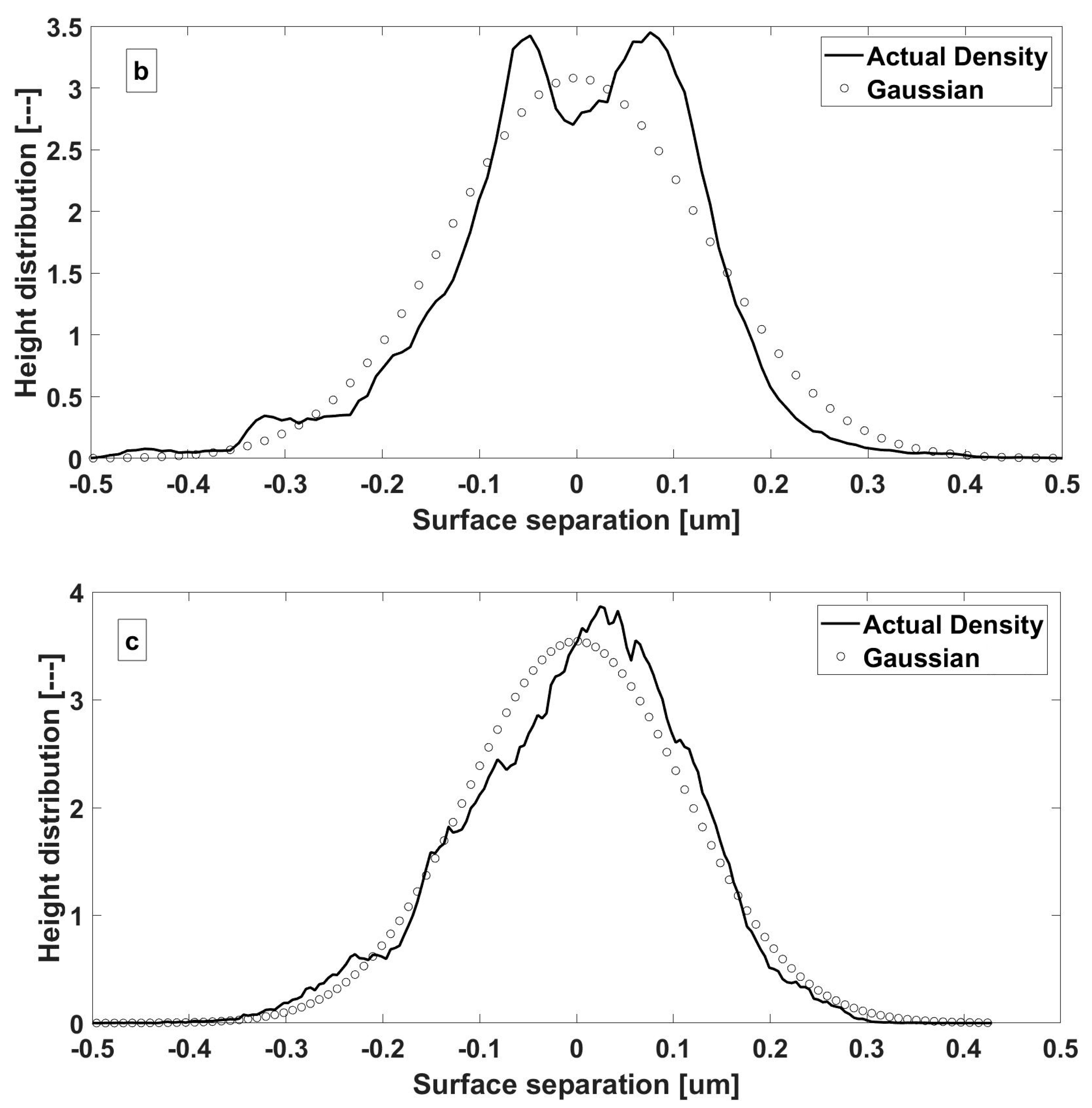
The boundary interaction model assumes a Gaussian of surface asperity heights. This can be verified using experimentally obtained surface topographies.
Figure 7 shows the real asperity height distributions for steel, DLC and WC-C surfaces. The results reveal that there is a reasonable conformity to a Gaussian distribution. Hence, the application of statistical functions for boundary interaction, assuming this distribution, is justified.
The rheological properties used throughout the investigation can be found in
Table 5, which correspond to a standard SAE 5W-20 lubricant. These properties were kept constant for all simulations performed. Other material properties necessary for the formulation can be found in
Table 6. The pressure coefficient of boundary shear strength of asperities is required for boundary friction calculation. It is the asperity level equivalent of the coefficient of friction which is expanded to macro-level (conjunction level) using the Greenwood and Tripp approach presented in
Section 2.5. The values of this coefficient for surfaces of this study are investigated and obtained using an Atomic Force Microscope (AFM) by Laderou et al. [
33].
The simulations performed are representative of a four-stroke engine at a speed of 3000 RPM and evaluate the behaviour of the system over two complete engine cycles. Since the simulation algorithm assumes a fully flooded cam–tappet conjunction as an initial condition, only the second engine cycle (720 to 1440 degrees) is presented, where the solution is considered to be settled after removing all transient effects. Simulation conditions are shown in
Table 7.
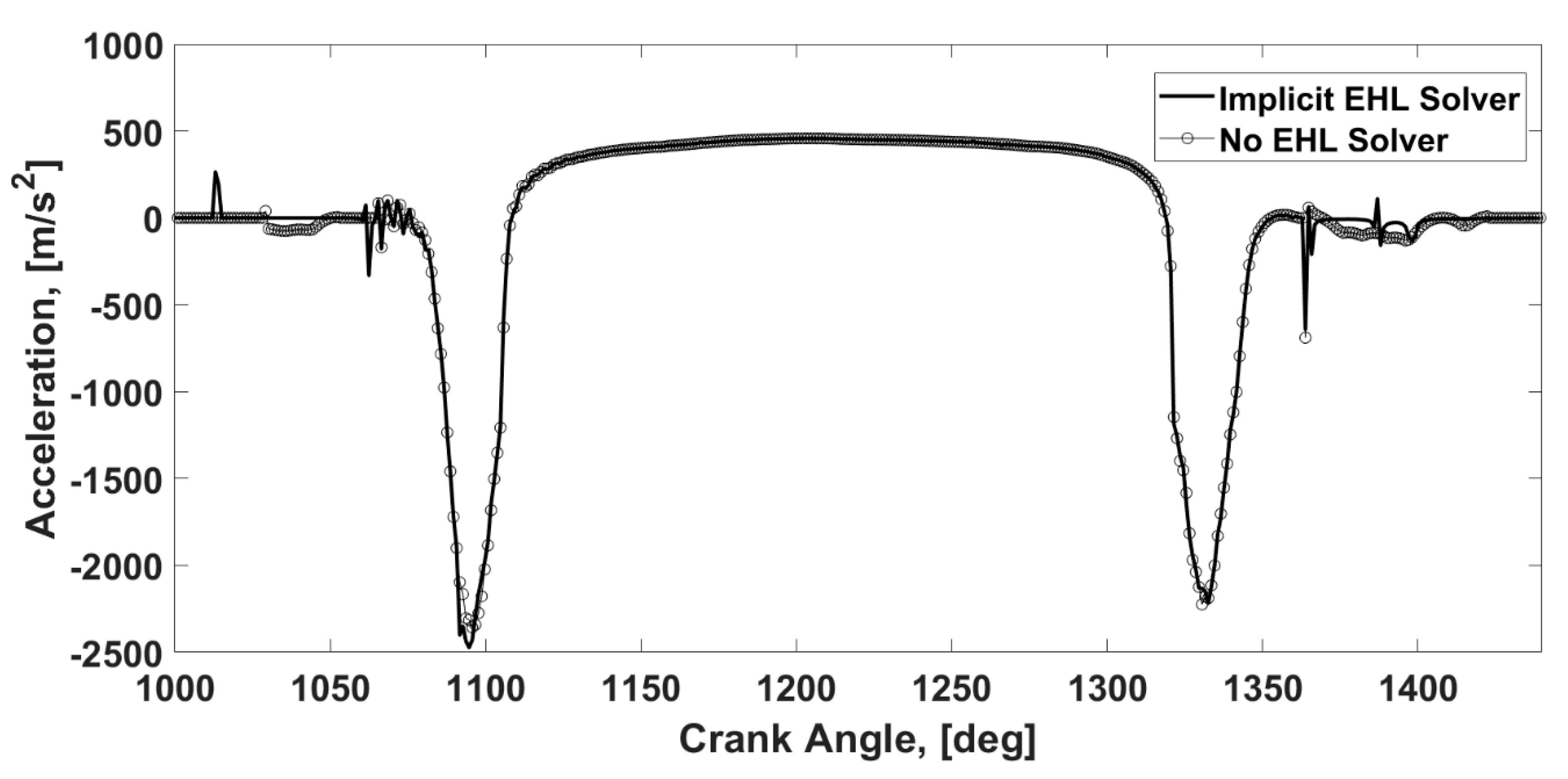
As the first step, the validity of using a full numerical EHL contact explicitly is investigated. For this purpose, two versions of multi-body dynamic model are simulated. The first model (referred to as “implicit EHL model” or “implicit” in figures) implicitly solves the numerical EHL model within the multi-body formulation. The second model (referred to as “no EHL solver” or “explicit” in figures) represents the multi-body dynamic model with a simple analytical tribology model instead of full numerical EHL solution. The tappet velocity and contact force from implicit and explicit models are plotted in
Figure 8 and
Figure 9, respectively. The results show the insignificant effect of using the implicit solution in comparison with the explicit one. The slight variation is observed in lightly loaded regions where the nature of the EHL regime is less pronounced, and the film thickness stiffness approached comparable values to those from solid contact. These are regions where the cam and tappet come into loaded contact or they are about to cease contact. They are shown schematically in
Figure 8. This effect is more pronounced in acceleration presented in
Figure 10. Overall, considering the insignificant effect of these regions as well as expected major effect of coatings in the highly loaded region, the explicit model is used for this investigation.
For the EHL solution, the contact load from
Figure 9 and speed of entertaining motion in
Figure 11 are used as inputs to the explicit coated EHL model. These results are used quasi-dynamically to simulate the behaviour of the lubricated contact during a complete cycle. For each case, the effects of coating are compared with uncoated steel. In addition, the effect of coating thickness is investigated.
The main reason for the insignificant effect of implicit modelling can be explained by significantly smaller contribution of the lubricant film to contact stiffness under elasticity domination regimes on the Greenwood Chart, such as EHL [
24]. For this purpose, the regimes of lubrication can be ascertained and verified using the Greenwood Chart [
24]. This chart utilises working conditions (mainly speed–load combinations) to summarise the contribution of elasticity and piezo-viscosity effects in the form of two dimensionless numbers,
and
. The combination of these numbers specifies if the regime of lubrication is piezo viscos/elastic (PE), piezo viscos/rigid (PR), iso viscos-elastic (IE) or iso viscos-rigid (IR). PE corresponds to the classical EHL, and IR corresponds to the classical hydrodynamic regimes. IE is the regime for so-called “soft-EHL”.
Figure 12 shows the working conditions of this study on the Greenwood chart. It should be noted that the boundaries in this graph are indicative and based on simplified analytical formulas [
24]. However, they roughly show the dominant effects. It is observed that some working points in the studies cycle fall in the hydrodynamic regime. Hydrodynamic condition corresponds to lightly loaded contacts. These points show the biggest difference between implicit and explicit models in
Figure 8,
Figure 9 and
Figure 10. Under higher loads, the working conditions approach PE and IE where the effect of film stiffness is diminished, and the implicit and explicit approached show a good agreement.
To further investigate the results of
Figure 12, the pressure and film thickness distributions of six points along a cycle are provided in
Figure 13. These points are considered at points 1 to 6 on
Figure 9 to show a variety of speed–load combinations. Each graph in
Figure 13 shows pressure and film thickness distributions for uncoated and WC-C-coated samples with 4
coating thickness. The results clearly show a variety of contact regimes from EHL, such as point 1 and 6, under high loads to the moderately deformed point 2. Under EHL conditions, the flattened film thickness as well as the secondary spike of the pressure distribution is apparent. It should be noted that the shape of pressure and film thickness distributions, as well as their values depend on both load and speed. Point 2, for example, resembles a near-zero velocity, leading to significantly lower film thickness.
It is also clear that the application of a WC-C coating leads to an expanded contact area, which in turn supports a thicker film thickness. This effect is due to the lower modulus of elasticity of the coated surfaces, which agrees with the generic results in
Figure 6. The expansion of the contact area and consequent increase in the film thickness value can be seen as a benefit of WC-C application, since it significantly affects the frictional and wear behaviour (the latter is not the subject of this study). This benefit is more pronounced under lightly loaded conditions such as points 2, 3, 4 and 5, which are away from the PE region on the Greenwood Chart.
Figure 14a shows the pressure and film thickness distributions of the DLC-coated surfaces in comparison with the WC-C-coated cam–tappets. The effect of coating thickness is also analysed by comparing the results of 1
coating thickness to those from 4 μm coating thickness. It is seen that the results for DLC and WC-C, as well as the behaviour of different coating thicknesses, are similar. This is due to the negligible effect of the coating thickness in comparison to the ratio of modulus of elasticity, as shown in
Figure 5 and
Figure 6. Similar values of modulus of elasticities from DLC and WC-C also yield similar pressure and film thickness distributions. The zoomed-in view in
Figure 14b shows the minute level of variation from DLC to WC-C and between coating thickness values.
Figure 15 is the variation of central film thickness during one cycle for 4
thickness of coatings. It is revealed that the major effect of coatings is observed in the moderately loaded region, as shown in
Figure 13 and
Figure 14. It accounts for a maximum increase of 41%, mainly observed at the centre of the high-load section. The consequence of this variation in the film thickness will be on durability as well as frictional performance. The former is not the subject of this study; hence, the effect of coatings on friction will be further investigated. It is also revealed that the difference between DLC and WC-C on the central film thickness is minute, as can also be observed in
Figure 14b. This will mean that any potential variation in friction between DLC and WC-C will be less related to the variation in the film thickness.
Figure 16 and
Figure 17 present the boundary contact load and boundary friction variations along a cycle. The results show a significant reduction in the boundary contact load (share of load carried by asperities) in coated samples. This is also reflected in the value of boundary friction force, which accounts for more than 95% at the moderately loaded region. This can be related to the improved (increased) film thickness in
Figure 15, which reduces the asperity interactions from both surfaces. Comparing two types of coating, WC-C reveals superior behaviour in terms of boundary friction with values which are ~70% lower in comparison with DLC. This comparative improvement can be attributed to minor differences in the values of pressure and film thickness.
Although boundary friction values are important, the absolute value of this quantity in comparison with viscous friction is lower. Hence, the value of viscous friction over a cycle is shown in
Figure 18 for different surfaces. The values in this figure are governed by the level of pressure as well as shear, which are in turn affected by film thickness and contact area. The results show that unlike boundary friction (governed by film thickness), the viscous friction in coated surfaces is higher than that in an uncoated surface. WC-C again reveals better frictional behaviour compared to DLC. The increased viscous friction can be attributed to the extended contact area, which is subject to the shear stress. Comparing the performance of WC-C as the better-performing coating with the uncoated surface, it gains a maximum of 0.44 N in boundary friction, whilst losing maximum of 0.43 N of viscous friction. Consequently, compared with DLC as a commonly used coating for cam–tappet contacts leading to an overall loss in the frictional values, the gain from WC-C coatings outweighs the loss.


 ,
, 


 , WC-C coated:
  ).
).


