Abstract
This paper proposes a compact K-band dual-circularly polarized antenna that can be implemented on a non-linear tag based on third-order intermodulation (IM3) for bio-sensing applications. The proposed antenna has the characteristics of being low-profile and lightweight, with opposite circular polarizations (CP) between ports. The non-linear tag-based bio-sensing scenario utilizes K-band millimeter wave frequencies, which allows for compact non-linear tags for attachment to the body. Also, the proposed antenna features dual-CP, which are for the reception and re-radiation of incident transmit signals and the IM3 responses, respectively. To this end, a two-port traveling-wave series-fed patch array with coplanar proximity coupling is designed. Here, to minimize the size of the antenna, we use only four circular patch elements with a modified diamond-shaped microstrip feedline. Through simulation and measurement, we demonstrate that the proposed antenna has an axial ratio of less than 3 dB from 23.25 GHz to 24.1 GHz, with the reflection coefficients below −10 dB and port-to-port coupling below −15 dB. These results indicate the potential utility of the proposed antenna as a tag antenna for non-linear detection-based bio-sensing applications.
1. Introduction
Wireless bio-signal sensing has received significant attention in recent years due to its possible applications in healthcare, fitness, and security. In particular, radar-based vital-sign sensing has received a great deal of attention [1,2,3,4,5,6]. However, these methods have limitations, such as signal interferences caused by human movements and surrounding clutter objects, which can lead to inaccuracy and performance degradation. To overcome these limitations, researchers have developed non-linear tags based on harmonic responses that incorporate components exhibiting non-linear behavior, such as diodes, transistors, and mixers [7,8]. These tags are attached to the human body and generate harmonic responses upon excitation by the radar-transmit pulses, which are then retransmitted back to the radar, carrying the vital signal information. By receiving and processing the harmonic responses returned from the non-linear tags only, unwanted signals and clutter at the fundamental frequency due to the movements from other parts of the body and surrounding clutter objects can be suppressed, thereby increasing the fidelity of the extracted vital signal information. On the other hand, using harmonic frequencies for receiving has its own constraints. Having to use the harmonic bands on the receiving end increases system complexity due to the large difference between transmit and receive frequencies, as well as higher path loss at the harmonic frequencies. To overcome the constraints of using harmonic tags, researchers have turned to the use of non-linear tags based on the third-order intermodulation (IM3) responses [9,10,11,12]. By transmitting two closely spaced frequencies, IM3 responses can be generated in the vicinity of the two fundamental bands, thereby allowing for the transmitter and receiver to use similar bands.
In general, the amplitude of non-linear responses is much smaller than that of fundamental signals. For example, a frequency tripler specifically designed to maximize third-order harmonics, such as the HMC-XTB110 in the K and Ka-band, exhibits a conversion loss of 18.3~21.2 dB [13]. Therefore, to efficiently detect the non-linear responses from non-linear tags, the antenna is a critical component to ensure good reception and re-radiation of the fundamental incident signals and non-linear responses, respectively [7,8]. However, using an antenna in the tag may increase the size of the tag, which may not be practical for attaching to the body if microwave frequencies are used. By utilizing the millimeter wave (mmWave) frequency bands, it is possible to minimize the size of the antenna and tag to be more compact [14], which can reduce discomfort when attached to the body. Therefore, using a mmWave frequency band can be a promising approach to wireless bio-signal sensing as it can achieve efficient sensing while minimizing the size of the tag and reducing the burden of attachment. For a reliable detection performance, the polarization alignment between the radar and the tag is important. However, when the tag is attached to the body, its orientation may vary, which causes the polarization to fluctuate. In this regard, using circular polarization inherently allows for polarization diversity, thereby improving the sensing performance. In recent years, there has been an increasing interest in using circularly polarized antennas for wireless bio-signal sensing due to their ability to provide more reliable signal reception in complex and dynamic environments compared to linearly polarized antennas [15,16,17,18]. Circular polarizations are known to effectively mitigate the effects of multipath propagation, fading, and polarization mismatch. Due to these advantages, circularly polarized antennas are widely used in various applications [19], including wireless communication systems and bio-signal sensing. Additionally, microstrip patch antennas provide benefits such as low-profile and low-cost fabrication, making them suitable for a wide range of applications, including healthcare. Moreover, ongoing efforts are focused on enhancing the performance of microstrip patch antennas [20,21,22,23,24,25].
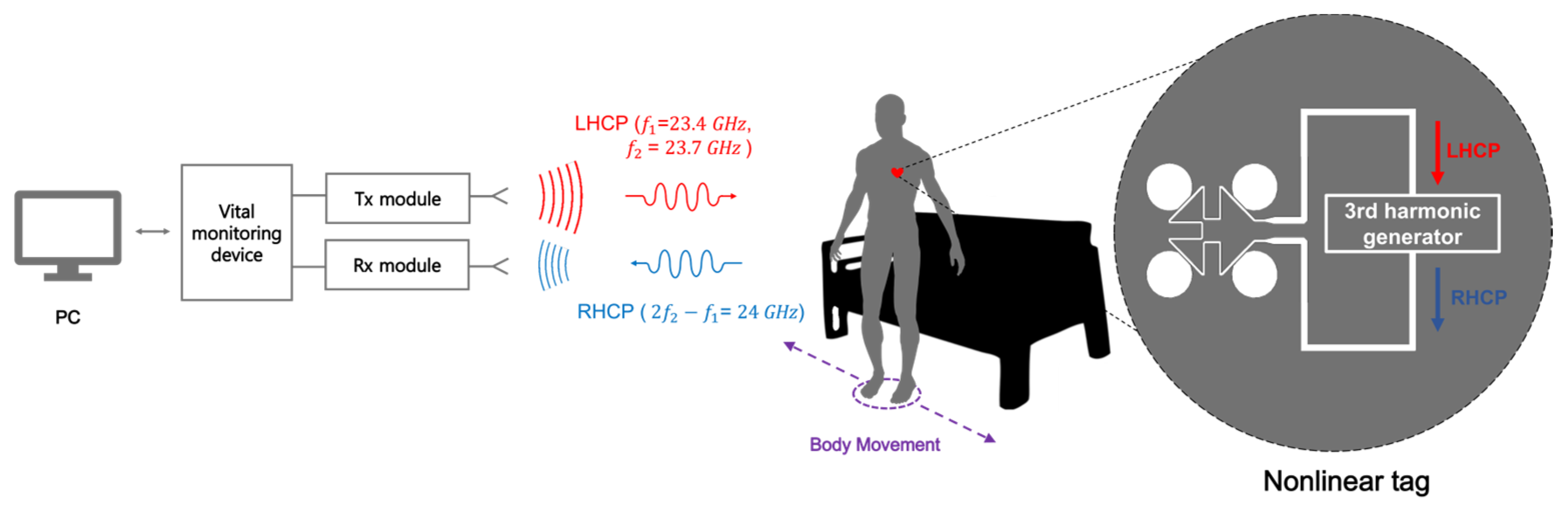
In this paper, we propose a dual-circularly polarized antenna design that can be utilized with a non-linear tag based on IM3 responses to enhance the accuracy and efficiency of bio-signal sensing. Figure 1 illustrates the conceptual system of bio-signal sensing using a two-tone signal as an input and IM3 responses as an output. Here, the two-tone signal consists of two closely spaced frequencies, namely f1 (23.4 GHz) and f2 (23.7 GHz), and is transmitted through a Tx system as a right-hand circularly polarized (RHCP) wave. The transmitted signal will then be received by the non-linear tag, which includes the proposed antenna and a third-harmonic generator. Once the two-tone signal is received by the tag antenna, it goes through the third-harmonic generator circuitry to produce IM3 responses, which in this case, is 24 GHz (2f2 − f1). The non-linear tag would then re-radiate the output IM3 responses with the vital sign information modulated as a left-hand circularly polarized (LHCP) wave, which will then be received and processed by the Rx system. Therefore, the proposed antenna is designed to operate from 23.4 to 24 GHz with a selective direction of circular polarization depending on which port is chosen while ensuring sufficient inter-port isolation with a transmission coefficient below −15 dB. To simplify the antenna structure and enable the implementation of dual-CP with a two-port configuration, the proposed design employs the traveling wave series-fed design [26,27,28,29,30]. Here, we use only four patch elements, unlike previous works, making it compact and compatible for use with a non-linear tag to detect bio-signals in dynamic and complex environments.
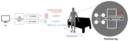
Figure 1.
Conceptual diagram of non-linear tag system with body attachment.
2. Proposed Antenna Design
2.1. Design and Configuration of Antenna
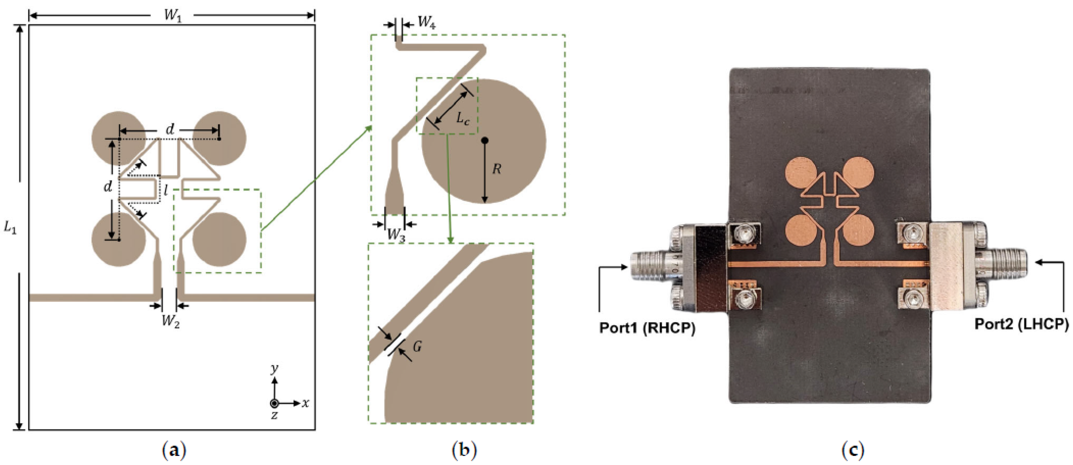
Figure 2 shows the configuration and realization of the proposed antenna. The K-band two-port array consists of a modified diamond-shaped microstrip feedline with tapered terminals and four circular patch elements on the top layer and a ground plane on the bottom layer. A 0.25 mm thick Rogers RT/Duroid 5880NS substrate with a relative permittivity () of 2.2 and loss tangent of 0.0009 is chosen as the dielectric material of the antenna. All simulations are performed using CST Microwave Studio Suite 2021. Each patch couples and radiates a fraction of energy from the guided waves traveling on the feedline from one port to the other. The gap between the traveling feedline and the element is constant with the parameter G to provide the same coupling strength. Figure 3 illustrates the current distribution of the proposed antenna at two different phases, namely 0 and 90 at a frequency of 24 GHz. This visual representation effectively depicts the resonance of the antenna when the traveling wave propagates from port 1 to port 2, resulting in RHCP. On the other hand, the excitation from port 2 to port 1 will yield LHCP. To ensure minimum signal leakage from one port to the other, it is necessary to obtain at least 15 dB of isolation between the ports. Any leakage between the ports can cause signal coupling interference, leading to signal degradation and reduced system performance. Therefore, in this paper, the operational bandwidth of the antenna is defined as the band where the reflection coefficients at each port are below −10 dB, and the transmission coefficients between the ports are below −15 dB. Maintaining in-phase alignment among the patches is crucial for achieving broadside radiation. Furthermore, the patches are positioned along the feedline with 90° angular rotation, determined by the number of elements. To ensure the desired in-phase condition, adjacent patches are separated by a microstrip line, and the length of this line is determined by the following Equation (1)
where is the guided wavelength on the feedline. The term provides a relative orientation between adjacent patches, providing a phase difference of 90°. The modified diamond-shaped feedline not only satisfies the desired in-phase condition between the patches but also maintains the spacing between the patches close to , where is the wavelength in free space. This design enables the proposed antenna to achieve compact size and high gain through the array. The radiated energy through the patch is determined by the small gap between each patch and the feedline through proximity coupling. That is, the smaller the gap, the larger the radiated energy through each patch. However, the gap size is limited by the available PCB fabrication process. Narrowing down the feedline width (W4) can increase the coupling strength, resulting in a more pronounced fringing field. However, 0.25 mm was chosen here, considering fabrication constraints and ensuring impedance matching. The circular patch resonates at the fundamental mode and generates CP through uniform current rotation. However, a single conventional circular patch does not provide a sufficient coupling rate due to its inherent structure. Therefore, in a previous study [26], a configuration with seven elements was used. In this study, we propose a modified circular patch to enhance the coupling rate and achieve a compact array structure. By utilizing only four elements, we ensure the desired operational bandwidth. As shown in Figure 2b, to enhance the coupling, the edge of the circular patch is truncated into a straight shape with a chord length (), forming a major segment shape, thereby increasing the length of the coupled section between the patch and the feedline. However, there is a trade-off between the increase in coupling and axial ratio when increases.
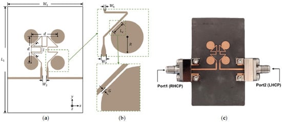
Figure 2.
The proposed antenna design: (a) overall configuration; (b) patch element geometry and feedline-to-element gap; (c) photographs of the proposed antenna. The final design dimensions are mm, mm, mm, mm, mm, mm, mm, , mm.

Figure 3.
Simulated surface current on the proposed antenna at two different phases: (a) 0° and (b) 90°.
2.2. Trade-Off between Total Efficiency and Axial Ratio Depending on Chord Length
To achieve effective proximity coupling and stable axial ratio with a small number of array elements and minimum gap condition imposed by the fabrication limitation, a simulation-based parametric study on the effect of is conducted. The evaluation is based on the average total efficiency and average axial ratio of the target frequencies of 23.4, 23.7, and 24 GHz. As increases, the coupling between the feed and elements increases, leading to an enhancement in both the total efficiency () and operational bandwidth, as depicted in Figure 4. However, the increase in results in a poor axial ratio since the rotation velocity of the surface current changes regardless of the given path length. Therefore, is set to 2.1 mm, which provides of over 80% and an axial ratio below 3 dB, as shown in Figure 4a. The initial value of for circular patches was set using the standard circular patch equation [31]. This results in an increase in the element impedance and a higher resonant frequency of the antenna. The optimal values are derived from the simulation, which is described in Figure 2.
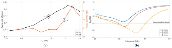
Figure 4.
Simulated (a) total efficiency and axial ratio; (b) transmission coefficients depending on .
3. Results and Discussion
3.1. Experiment Result
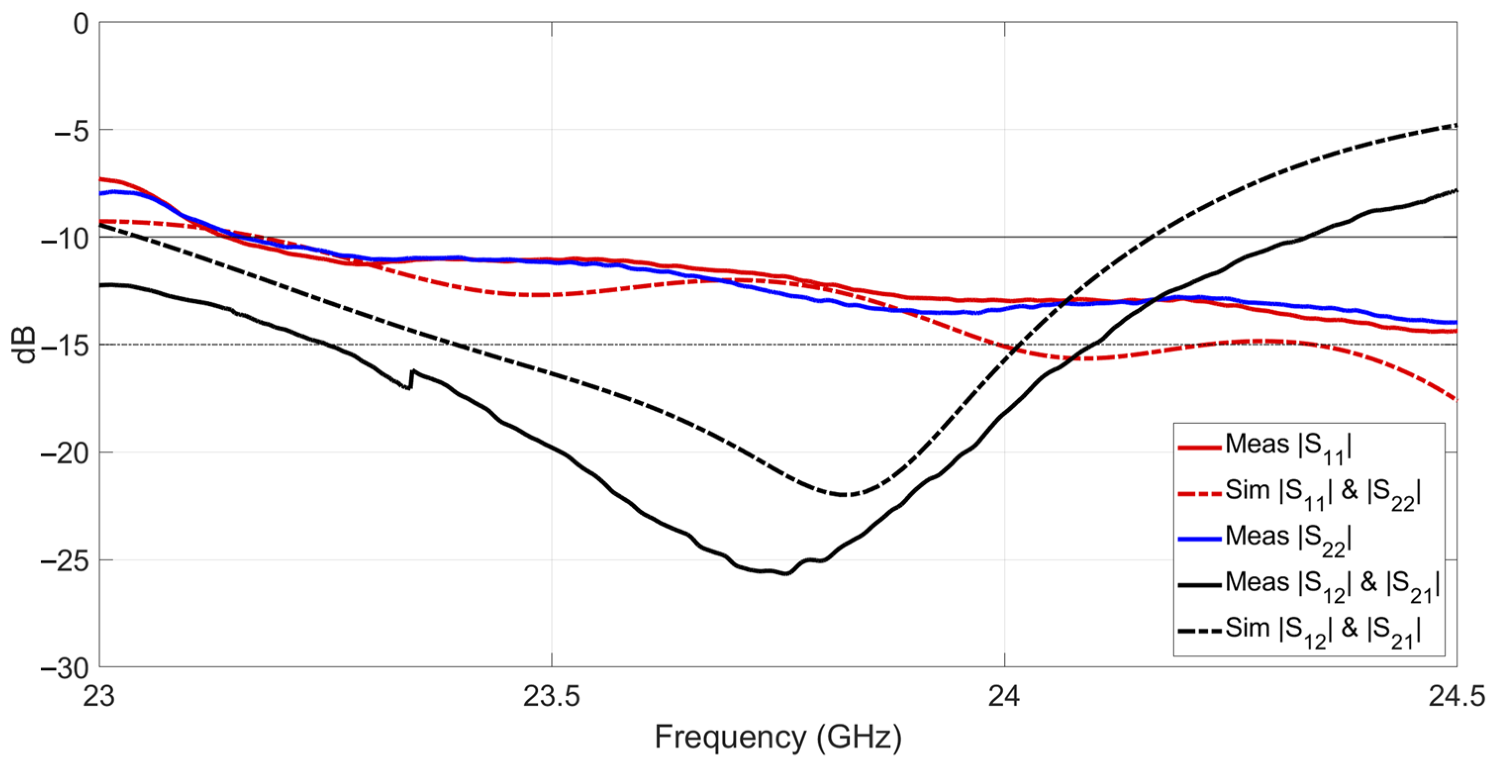
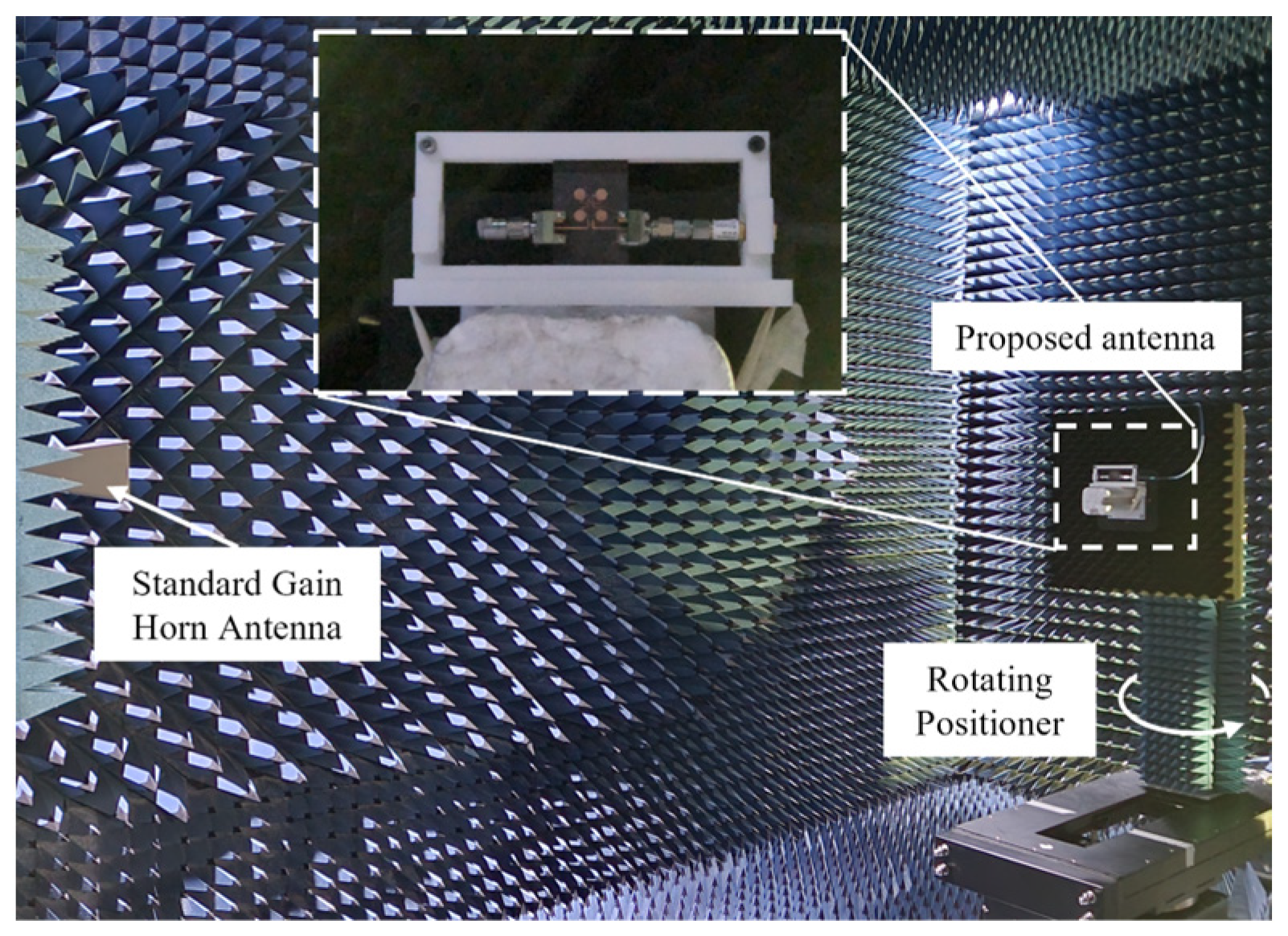
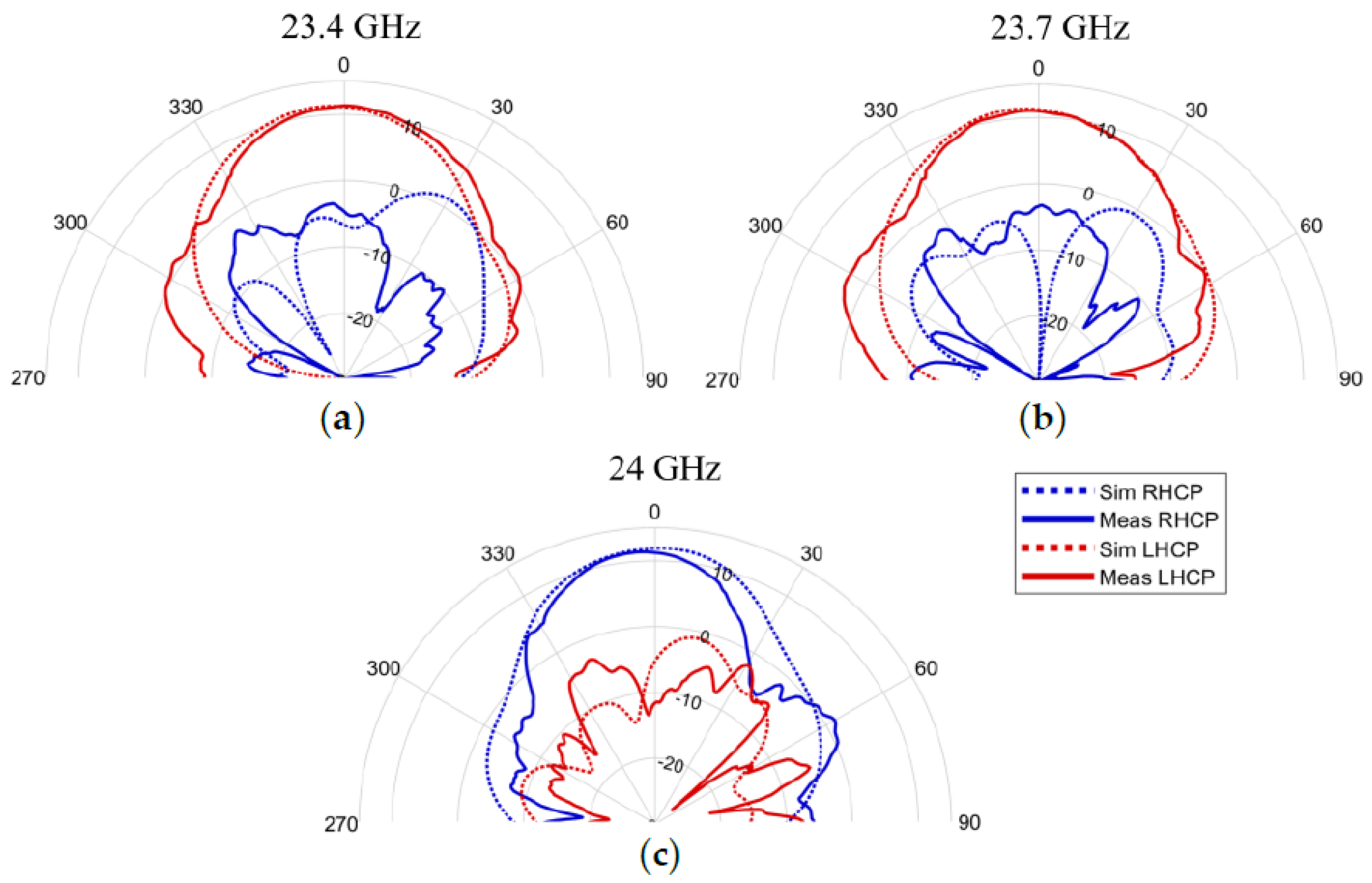
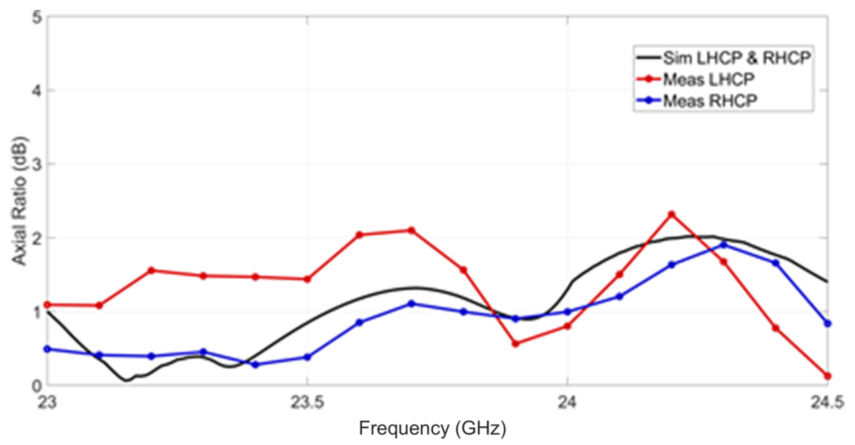
The fabricated structure of the antenna is shown in Figure 2c. The reflection and transmission coefficients are measured using a vector network analyzer (Anritsu MS 46122B, Anritsu Company, Morgan Hill, CA, USA). The measured and simulated results are plotted in Figure 5, which demonstrates that the measured reflection coefficients (|S11|,|S22|) are under −10 dB and transmission coefficients (|S12|,|S21|) are under −15 dB from 23.4 to 24 GHz, implying good impedance match and port-to-port isolation, respectively. The measured transmission coefficients show a slight discrepancy compared to the simulated data, with the measured values consistently lower by a few dB across the entire bandwidth. This difference can be attributed to various factors, including unaccounted dielectric losses, slight misalignment of the connectors, and the inherent sensitivity of the fabrication process at mm-wave frequencies. The radiation characteristics of the fabricated proposed antenna are measured in an anechoic chamber. To conduct the measurements, the proposed antenna is mounted on a plastic jig, as depicted in Figure 6. The radiation pattern in the azimuthal direction is measured by incrementally rotating the positioner at 1 intervals. Figure 7 shows the simulated and measured radiation patterns at 23.4, 23.7, and 24 GHz, which exhibit a generally similar trend, except that the variations in the measured radiation patterns of cross-polarization can be attributed to unwanted wave reflections and interferences from the jig or terminator/connector and other objects in the apparatus. The maximum gain is measured to be 11.34, 11.08, and 11.41 dBi at 23.4, 23.7, and 24 GHz, respectively. Figure 8 shows the simulated and measured axial ratio from 23.5 to 24 GHz.
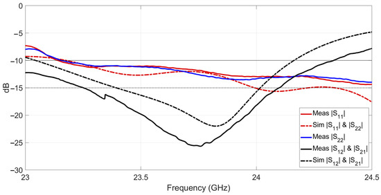
Figure 5.
Simulated and measured S-parameters. The shaded area is the operational bandwidth.
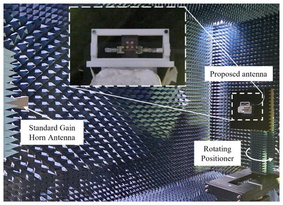
Figure 6.
Photograph of measurement setup in an anechoic chamber.
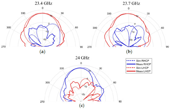
Figure 7.
Simulated and measured radiation patterns: (a) 23.4; (b) 23.7; (c) 24 GHz.
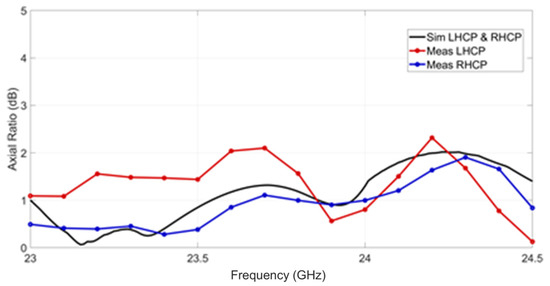
Figure 8.
Simulated and measured axial ratios. The shaded area is the operational bandwidth.
3.2. Comparative Analysis
The proposed antenna, which is a compact and low-profile structure, exhibits high gain. A comparison of the proposed antenna characteristics with other antennas presented in the literature [32,33,34,35] is given in Table 1. Since the operational bandwidth is from 23.25 GHz to 24.1 GHz, it can receive LHCP signals at 23.4 and 23.7 GHz through port 2 and radiate components in RHCP through port 1, indicating that the proposed structure can operate as a tag antenna in the aforementioned applications.

Table 1.
Comparison of proposed and reference antennas.
3.3. Performance Prediction of a Notional Sensing System
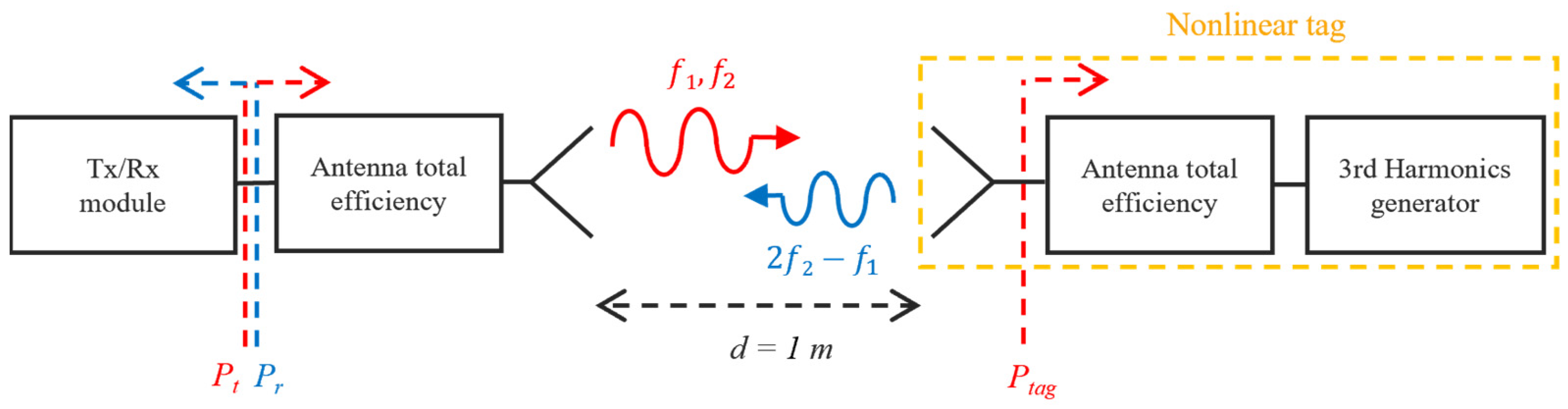
To predict the performance of bio-sensing using a non-linear tag, a notional system shown in Figure 9 is considered. This system consists of the proposed antenna and a passive frequency tripler circuit. By utilizing the measured peak gain of the proposed antenna and the antenna total efficiency obtained through simulations, we established the link budget of the notional system, as shown in Table 2. The system operates with a two-tone signal at a power level of 27 dBm (f1 = 23.4 GHz, f2 = 23.7 GHz) transmitted from the Tx/Rx module. The non-linear tag, positioned 1 m away from the radar, receives the transmit signal with an input power (Ptag) of −10.6 dBm. The IM3 response signal (2f2 − f1) generated by the third-harmonic generator is then re-radiated and received by the Tx/Rx module with a power of −68.9 dBm. These findings provide valuable insights into the performance and feasibility of the proposed system for bio-sensing application.
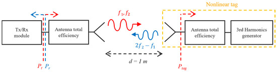
Figure 9.
Block diagram of notional system where Pt refers to transmitted power and Pr refers to received power and Ptag is an incident power to the non-linear tag.
Table 2.
Link budget of notional system.
4. Conclusions
In this paper, we have presented a millimeter-wave dual-circularly polarized traveling-wave series-fed patch array that serves as a promising candidate for a non-linear tag antenna. Our primary goal was to design an antenna that fulfills the requirements of reduced size, enhanced proximity coupling, and separate circular polarization orientations for input and output signals. We have successfully achieved these goals through the utilization of circular major segment patches and a modified diamond-shaped feedline. The measured results have demonstrated satisfactory performance in terms of isolation between ports and reflection coefficient within the desired frequency band while maintaining the desired axial ratio for each circular polarization. The proposed antenna design exhibits notable advantages, including lightweight, low-profile, and robust performance. These characteristics make it suitable for compact tag implementation on the body for bio-signal sensing applications.
Author Contributions
Conceptualization, W.L., S.O. and S.K.H.; data curation, W.L. and S.K.H.; formal analysis, W.L.; funding acquisition, S.K.H.; investigation, S.O.; methodology, W.L., S.O. and S.K.H.; project administration, S.K.H.; validation, W.L. and S.O.; writing—original draft, W.L.; writing—review and editing, S.O., W.L. and S.K.H. All authors have read and agreed to the published version of the manuscript.
Funding
This work was supported by the Korea Institute for Advancement of Technology (KIAT) (Grant No. P0017123, The Competency Development Program for Industry Specialists).
Institutional Review Board Statement
Not applicable.
Informed Consent Statement
Not applicable.
Data Availability Statement
Data sharing is not applicable.
Conflicts of Interest
The authors declare no conflict of interest.
References
- Lin, J.C.; Kiernicki, J.; Kiernicki, M.; Wollschlaeger, P.B. Microwave Apexcardiography. IEEE Trans. Microw. Theory Tech. 1979, 27, 618–620. [Google Scholar] [CrossRef]
- Lin, J.C. Noninvasive microwave measurement of respiration. Proc. IEEE 1975, 63, 1530. [Google Scholar] [CrossRef]
- Droitcour, A.; Lubecke, V.; Lin, J.; Boric-Lubecke, O. A microwave radio for Doppler radar sensing of vital signs. In Proceedings of the IEEE MTT-S International Microwave Symposium Digest, Phoenix, AZ, USA, 20–24 May 2001; Volume 1, pp. 175–178. [Google Scholar] [CrossRef]
- Droitcour, A.D.; Boric-Lubecke, O.; Lubecke, V.M.; Lin, J.; Kovacs, G.T.A. Range correlation and I/Q performance benefits in single-chip silicon Doppler radars for noncontact cardiopulmonary monitoring. IEEE Trans. Microw. Theory Tech. 2004, 52, 838–848. [Google Scholar] [CrossRef]
- Kim, B.; Jin, Y.; Choi, Y.; Lee, J.; Kim, S. Low-Complexity Super-Resolution Detection for Range-Vital Doppler Estimation FMCW Radar. J. Electromagn. Eng. Sci. 2021, 21, 236–245. [Google Scholar] [CrossRef]
- Peng, K.-C.; Sung, M.-C.; Wang, F.-K.; Horng, T.-S. Noncontact Vital Sign Sensing Under Nonperiodic Body Movement Using a Novel Frequency-Locked-Loop Radar. IEEE Trans. Microw. Theory Tech. 2021, 69, 4762–4773. [Google Scholar] [CrossRef]
- Nourshamsi, N.; Vakalis, S.; Nanzer, J.A. Joint Detection of Human and Object Motion Using Harmonic Micro-Doppler Radar and Harmonic Tags. IEEE Antennas Wirel. Propag. Lett. 2020, 19, 930–934. [Google Scholar] [CrossRef]
- Zhu, L.; Hà, T.D.; Chen, Y.-H.; Huang, H.; Chen, P.-Y. A Passive Smart Face Mask for Wireless Cough Monitoring: A Harmonic Detection Scheme with Clutter Rejection. IEEE Trans. Biomed. Circuits Syst. 2022, 16, 129–137. [Google Scholar] [CrossRef]
- Mishra, A.; McDonnell, W.; Wang, J.; Rodriguez, D.; Li, C. Intermodulation-Based Nonlinear Smart Health Sensing of Human Vital Signs and Location. IEEE Access 2019, 7, 158284–158295. [Google Scholar] [CrossRef]
- Viikari, V.; Seppa, H. RFID MEMS Sensor Concept Based on Intermodulation Distortion. IEEE Sens. J. 2009, 9, 1918–1923. [Google Scholar] [CrossRef]
- Mishra, A.; Wang, J.; Rodriguez, D.; Li, C. Utilizing Passive Intermodulation Response of Frequency-Modulated Continuous-Wave Signal for Target Identification and Mapping. IEEE Sens. J. 2021, 21, 17817–17826. [Google Scholar] [CrossRef]
- Mishra, A.; Li, C. A Low Power 5.8-GHz ISM-Band Intermodulation Radar System for Target Motion Discrimination. IEEE Sens. J. 2019, 19, 9206–9214. [Google Scholar] [CrossRef]
- ANALOGDEVICES Product HMC-XTB110 Data Sheet. Available online: https://www.analog.com/en/products/hmc-xtb110.html#product-overview (accessed on 15 May 2023).
- Tahir, N.; Brooker, G. Toward the Development of Millimeter Wave Harmonic Sensors for Tracking Small Insects. IEEE Sens. J. 2015, 15, 5669–5676. [Google Scholar] [CrossRef]
- Lee, J.H.; Hwang, J.M.; Choi, D.H.; Park, S.O. Noninvasive Biosignal Detection Radar System Using Circular Polarization. IEEE Trans. Inf. Technol. Biomed. 2009, 13, 400–404. [Google Scholar] [CrossRef]
- Jiang, Z.H.; Gregory, M.D.; Werner, D.H. Design and Experimental Investigation of a Compact Circularly Polarized Integrated Filtering Antenna for Wearable Biotelemetric Devices. IEEE Trans. Biomed. Circuits Syst. 2016, 10, 328–338. [Google Scholar] [CrossRef]
- Bhattacharjee, S.; Maity, S.; Chaudhuri, S.R.B.; Mitra, M. A Compact Dual-Band Dual-Polarized Omnidirectional Antenna for On-Body Applications. IEEE Trans. Antennas Propag. 2019, 67, 5044–5053. [Google Scholar] [CrossRef]
- Yang, Z.J.; Xiao, S.Q.; Zhu, L.; Wang, B.Z.; Tu, H.L. A Circularly Polarized Implantable Antenna for 2.4-GHz ISM Band Biomedical Applications. IEEE Antennas Wirel. Propag. Lett. 2017, 16, 2554–2557. [Google Scholar] [CrossRef]
- Oh, S.; Park, H.S.; Oh, J.; Hong, S.K. Circularly Polarized S/C Dual-Band Antenna for Nonlinear Detection. IEEE Antennas Wirel. Propag. Lett. 2022, 21, 1467–1471. [Google Scholar] [CrossRef]
- Liu, B.; Sha, K.; Jia, Y.Q.; Huang, Y.H.; Hu, C.C.; Li, L.; Wang, D.W.; Zhou, D.; Song, K.X. High quality factor cold sintered LiF ceramics for microstrip patch antenna applications. J. Eur. Ceram. Soc. 2021, 41, 4835–4840. [Google Scholar] [CrossRef]
- Liu, B.; Sha, K.; Zhou, M.F.; Song, K.X.; Huang, Y.H.; Hu, C.C. Novel low-εr MGa2O4 (M = Ca, Sr) microwave dielectric ceramics for 5 G antenna applications at the Sub-6 GHz band. J. Eur. Ceram. Soc. 2021, 41, 5170–5175. [Google Scholar] [CrossRef]
- Din, I.U.; Ullah, W.; Abbasi, N.A.; Ullah, S.; Shihzad, W.; Khan, B.; Jayakody, D.N.K. A Novel Compact Ultra-Wideband Frequency-Selective Surface-Based Antenna for Gain Enhancement Applications. J. Electromagn. Eng. Sci. 2023, 23, 188–201. [Google Scholar] [CrossRef]
- Vincenti Gatti, R.; Rossi, R.; Dionigi, M. Single-Layer Line-Fed Broadband Microstrip Patch Antenna on Thin Substrates. Electronics 2021, 10, 37. [Google Scholar] [CrossRef]
- Raptis, V.; Tatsis, G.; Votis, C.; Chronopoulos, S.K.; Christofilakis, V.; Kostarakis, P. Tuning Techniques for Planar Antennas in Wireless Communication. In Proceedings of the AIP Conference 7th International Conference of the Balkan Physical Union, Alexandroupolis, Greece, 9–13 September 2009; pp. 1053–1057. [Google Scholar] [CrossRef]
- Raptis, V.; Tatsis, G.; Votis, C.; Chronopoulos, S.K.; Christofilakis, V.; Kostarakis, P. Active Tuning Antennas for Wireless Communication. In Proceedings of the AIP Conference 7th International Conference of the Balkan Physical Union, Alexandroupolis, Greece, 9–13 September 2009; pp. 1058–1062. [Google Scholar] [CrossRef]
- Chen, S.J.; Fumeaux, C.; Monnai, Y.; Withayachumnankul, W. Dual Circularly Polarized Series-Fed Microstrip Patch Array with Coplanar Proximity Coupling. IEEE Antennas Wirel. Propag. Lett. 2017, 16, 1500–1503. [Google Scholar] [CrossRef]
- Yang, Y.H.; Guo, J.L.; Sun, B.H.; Cai, Y.M.; Zhou, G.N. The Design of Dual Circularly Polarized Series-Fed Arrays. IEEE Trans. Antennas Propag. 2019, 67, 574–579. [Google Scholar] [CrossRef]
- Yasin, T.; Baktur, R. Bandwidth Enhancement of Meshed Patch Antennas Through Proximity Coupling. IEEE Antennas Wirel. Propag. Lett. 2017, 16, 2501–2504. [Google Scholar] [CrossRef]
- Chen, S.J.; Withayachumnankul, W.; Monnai, Y.; Fumeaux, C. Linear Series-Fed Patch Array with Dual Circular Polarization or Arbitrary Linear Polarization. In Proceedings of the International Conference on Electromagnetics in Advanced Applications (ICEAA), Granada, Spain, 9–13 September 2019; pp. 0365–0369. [Google Scholar] [CrossRef]
- Lee, J.E.; Lee, J.M.; Hwang, K.G.; Seo, D.W.; Shin, D.S.; Lee, C.H. Capacitively Coupled Microstrip Comb-Line Array. Antennas for Millimeter-Wave Applications. IEEE Antennas Wirel. Propag. Lett. 2020, 19, 1336–13394. [Google Scholar] [CrossRef]
- Balanis, C. Antenna Theory: Analysis and Design; John and Wiley and Sons: Hoboken, NJ, USA, 2005; pp. 815–823. [Google Scholar]
- Kortright, M.A.B.; Simons, R.N. K-Band Cross-Aperture Coupled Circularly Polarized Dual Frequency Microstrip Patch Antenna with Single Feed. In Proceeding of the IEEE International Symposium on Antennas and Propagation & USNC/URSI National Radio Science Meeting, Boston, MA, USA, 8–13 July 2018; pp. 337–338. [Google Scholar] [CrossRef]
- Kortright, M.A.B.; Simons, R.N. Feasibility Study of K-band E-Shaped Circularly Polarized Microstrip Patch Antenna Elements for SATCOM Receive Arrays. In Proceeding of IEEE International Symposium on Antennas and Propagation & USNC/URSI National Radio Science Meeting, Boston, MA, USA, 8–13 July 2018; pp. 345–346. [Google Scholar] [CrossRef]
- Luo, Q.; Gao, S.; Zhang, L. Wideband multilayer dual circularly-polarised antenna for array application. Electron. Lett. 2015, 51, 2087–2089. [Google Scholar] [CrossRef]
- Stark, A.; Jacob, A.F. A single-feed star-slot-coupled patch antenna with circular polarization. In Proceeding of German Microwave Conference Digest of Papers, Berlin, Germany, 15–17 March 2010; pp. 70–73. [Google Scholar]


Disclaimer/Publisher’s Note: The statements, opinions and data contained in all publications are solely those of the individual author(s) and contributor(s) and not of MDPI and/or the editor(s). MDPI and/or the editor(s) disclaim responsibility for any injury to people or property resulting from any ideas, methods, instructions or products referred to in the content. |
© 2023 by the authors. Licensee MDPI, Basel, Switzerland. This article is an open access article distributed under the terms and conditions of the Creative Commons Attribution (CC BY) license (https://creativecommons.org/licenses/by/4.0/).