Article

Model Test of Stress and Displacement of Recyclable Anchor Rod Support Structure

1
Anhui Province Key Laboratory of Green Building and Assembly Construction, Anhui Institute of Building Research & Design, Heifei 230031, China
2
School of Civil Engineering and Architecture, Anhui University of Science and Technology, Huainan 232001, China
*
Author to whom correspondence should be addressed.
Appl. Sci. 2023, 13(13), 7713; https://doi.org/10.3390/app13137713
Submission received: 21 April 2023 / Revised: 26 June 2023 / Accepted: 27 June 2023 / Published: 29 June 2023

Abstract

:
A recyclable bolt is a kind of green supporting component that can save materials and weaken the influence of underground engineering. It has a good application prospect in foundation pit and slope-supporting engineering, as well as a high economic and environmental effect in future engineering construction. The stress and displacement change of the foundation pit with a recoverable bolt was analyzed by performing a laboratory model test. The test results demonstrated that in the process of excavation, the recyclable anchor rod supporting the structure effectively limited the horizontal displacement of the pile top and had a significant constraint effect on the surface settlement. With the increase in the excavation depth, both the axial force value of the recyclable anchor rod and the maximum bending moment value of the supporting pile increased gradually, and the maximum bending moment value of the supporting pile appeared at 1/3 H. After the excavation, the maximum horizontal displacement of the pile top was 0.04% of the excavation depth. The failure recovery of the anchor was the primary factor contributing to the increased deformation of the foundation pit during the backfilling stage. Upon completion of the backfilling process, the final deformation of the foundation pit reached 0.1% of the excavation depth; this can meet safety requirements, reduce the waste of building materials, and conform to the concept of green sustainable development.

1. Introduction

The rapid development of the social economy and science and technology contributes to the gradual expansion of urban space, and the development of underground space has become the main development trend at present. The deep foundation pit develops in a deeper and larger direction, inducing higher requirements for the safety and applicability of deep foundation pit support [1,2,3]. Among them, the pile and anchor support is particularly suitable for complex construction environments, can shorten the construction period, and is widely applied in foundation pits. Zhang Qinxi et al. [4] adopted the pile–anchor rod support in a complex environment, realized the support, and obtained the internal force distribution law of the supporting structure. Li Ming et al. [5] effectively controlled the overall deformation of surrounding buildings and supporting structures using the pile and anchor rod support in the construction environment of adjacent buildings. Peng et al. [6] analyzed the pile–anchor rod support structure and obtained the change rule of the surface settlement around the foundation pit with excavation.
An anchor bolt, as a temporary supporting structure for underground engineering construction, is left underground after it plays its role. Since it is considered concealed engineering, its length is difficult to trace after the completion of construction, and sometimes it will exceed the red line, affecting future underground construction and causing a waste of resources that cannot be recovered. As a result, the subsequent underground engineering construction is impeded [7,8,9,10]. Driven by the sustainable development strategy of “green building materials, green buildings”, recoverable bolt technology will become the mainstream development trend. Many researchers have proposed the concept of new recyclable support and applied it in practical engineering projects [11,12,13,14]. Gong Xiaonan et al. [15] elaborated on the commonly used recycling mechanism of recyclable anchor rods based on the application status of recyclable anchor rod technology and provided suggestions on its research and development direction. Du Chenchen et al. [16] conducted a pull-out test on the new recyclable anchor rod and revealed the distribution law of the surrounding soil’s tensile stress in the pulling-out process of the recyclable anchor rod. Chen Zhibo et al. [17] investigated the bearing deformation characteristics of the recyclable anchor rod, suggesting that the bearing characteristics of the recyclable anchor rod were better when the horizontal dip angle of the recyclable anchor rod was between 15° and 35°. Yu Li et al. [18] performed model tests of the pile–anchor rod support and prefabricated support under the same conditions, concluding that a prefabricated support structure could better limit displacement. Liu Guosheng et al. [19] discussed the working mechanism of recyclable anchor rods and verified that recyclable anchor rods had a good bearing performance. Li Hongjun et al. [20] applied recyclable anchor rod anchor rods in deep foundation pit engineering. The engineering example demonstrated that the recyclable anchor rod did not affect the surrounding site on the premise of ensuring safe recovery. To sum up, the use of recyclable anchor rods can assure good bearing characteristics and be recycled to curtail resource waste.
At present, the analysis of the stress and deformation characteristics of pile–anchor rod support structures focuses on numerical simulation [21,22,23]; however, it is worth noting that field testing for this research entails a lengthy cycle and high costs. While the research on pile–anchor-supporting structures mainly focuses on common anchors, little attention has been given to recoverable anchors and the subsequent displacement changes in the foundation pit upon anchor recovery. Evaluating the displacement changes in the supporting structure after bolt recovery remains a crucial indicator for measuring the stability of the foundation pit. Based on this, an indoor model test was carried out to investigate the stress and deformation characteristics of the recoverable bolt supporting the structure during excavation and bolt recovery.

2. Model Test Scheme

2.1. Experimental Similarity Ratio Design
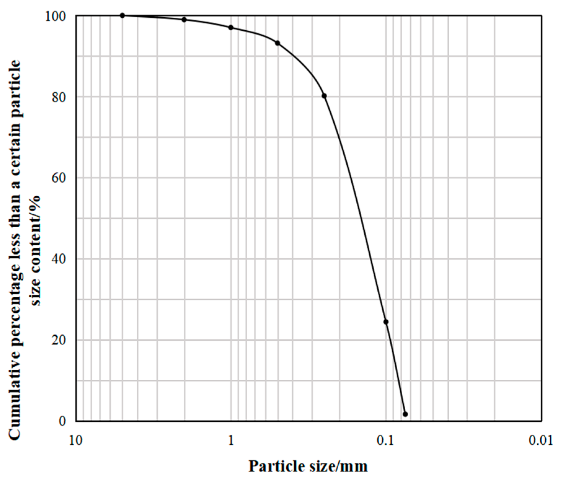
The similarity ratio of each dimension and parameter were determined using the following:
Geometric criteria:
C L = L p L m
C D = D p D m
C D = D 1 d 1
In the formula, Lp represents the width of the foundation pit in practical engineering, Lm represents the width of foundation pit in model test, Dp represents the depth of the foundation pit in practical engineering, Dm represents the depth of foundation pit in model test, D1 represents the diameter of support piles in practical engineering, and d1 represents the diameter of supporting pile in model test.
Stress similarity ratio:
C E = E 1 E
C E = E 2 E
In the formula, E1 represents the elastic modulus of the prototype’s supporting pile, E represents the elastic modulus of the model’s supporting pile, E2 represents the elastic modulus of the prototype anchor, and E’ represents the elastic modulus of the model anchor. Table 1 shows the model test similarity ratio.

2.2. Test Material

River sand was selected as the test soil and screened. Craig [24] reported that the particle size effect is ignorable when the ratio of the structure size to the maximum particle size is 40. Figure 1 illustrates the particle grading curve of the sand used in the test, obtained according to the Geotechnical Test Methods and Standards [25] in Chapter 8; a particle analysis test screening method was employed to test the sand screening process.

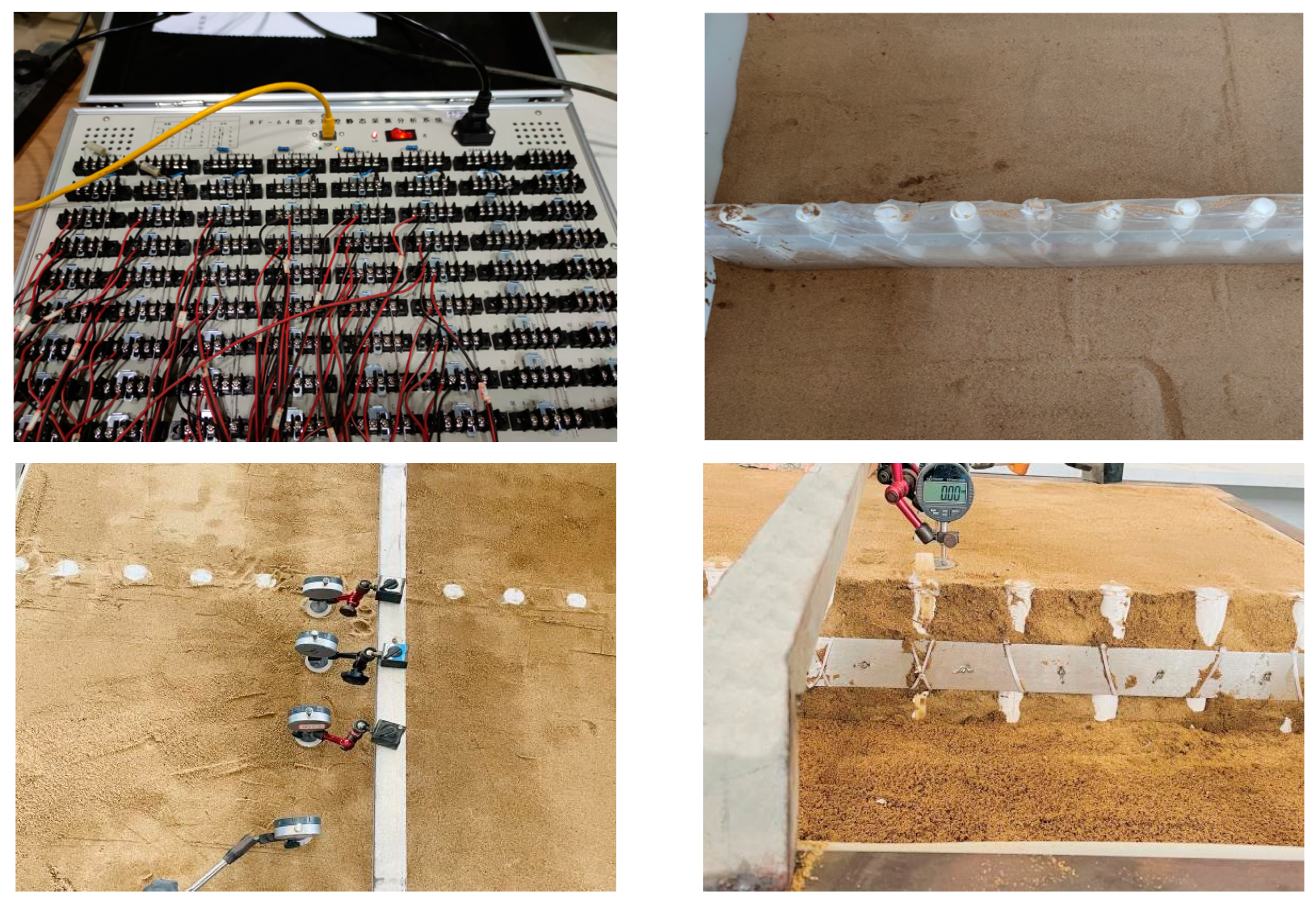
2.3. Model Test Device

The size of the model box used in the model test was 100 cm × 100 cm × 75 cm (length × width × height). The model box was composed of a 1 cm thick PP plate and a 0.5 cm thick steel plate. The model pile was composed of PVC pipe with a length of 65 cm and an outer diameter of 3.2 cm, an anchor rod with a length of 55 cm, and a steel pipe with a diameter of 0.32 cm.
The model test is exhibited in Figure 2. Seven groups of strain gauges were pasted on the model’s pile body, and an earth pressure box was placed 2 cm behind the supporting pile. During the excavation of the foundation pit, a dial indicator was utilized to measure the displacement, and a small hard pad was placed every 15 cm at the position where the settlement needed to be measured to reduce the error. Surface settlement and the stress and deformation of the supporting pile in the process of the foundation pit excavation were investigated following the strain change and dial indicator measurement results during the test, the axial force of the anchor rod.
The elastic modulus of the supporting pile and anchor rod was measured by the simply supported beam method. The dial indicator was placed in the middle of the supporting pile and anchor rod, and the displacement was measured by step loading at the mid-span position. The elastic modulus can be calculated by:
E = F l 3 48 I f
where F denotes the load acting at the midpoint of the model pile (N); I represents the modulus of inertia (m4); f signifies the deflection (m); l indicates the length between the model pile fulcrum (m).

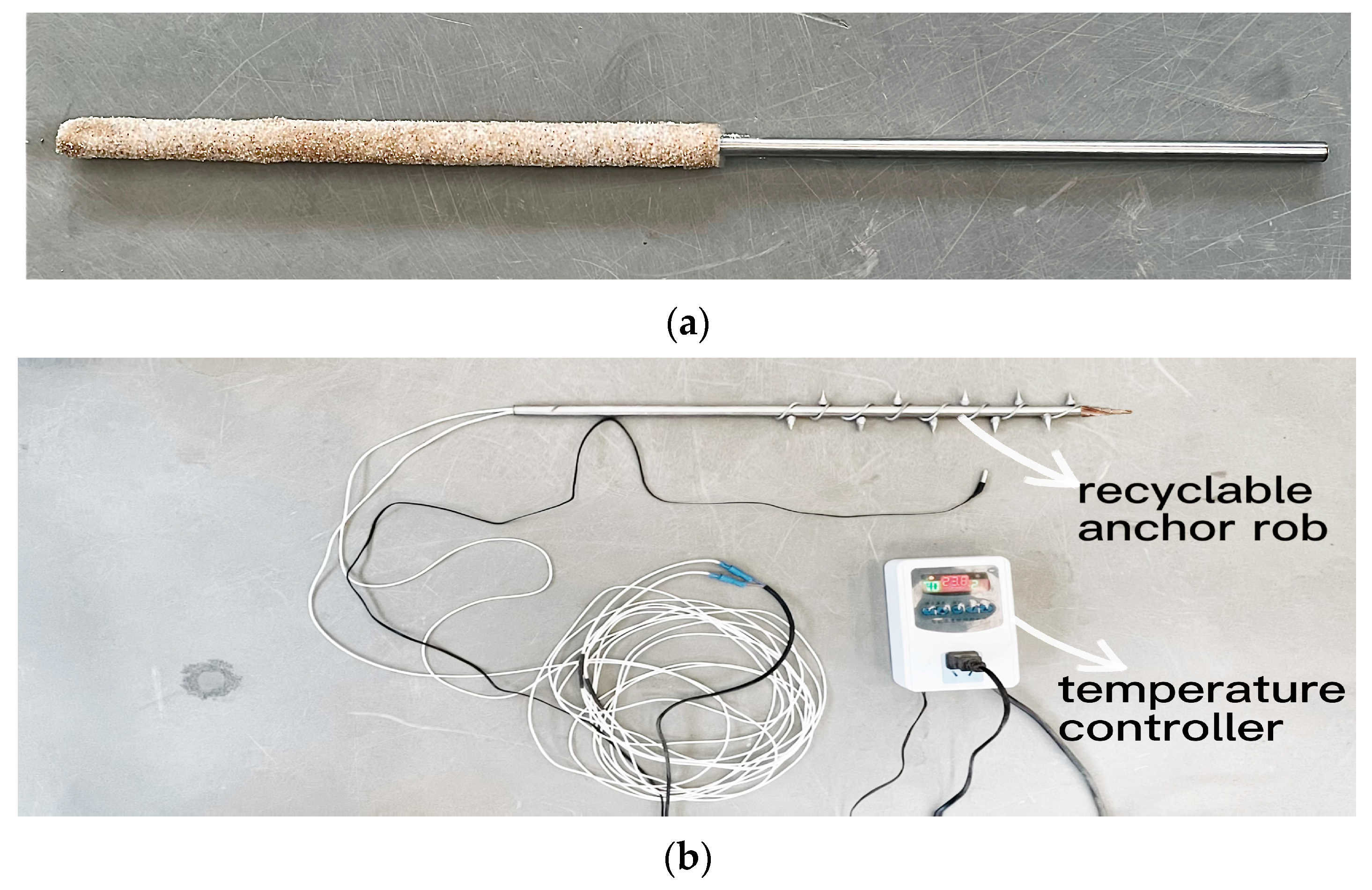
2.4. Introduction of the Test’s Recoverable Anchor Bolt

The anchor bolt used in the test is a new type of recoverable anchor bolt that adopts hot melting to fuse the friction nail and then pull out the bolt body. This kind of anchor bolt can be largely recovered, and only the fused friction nails are left in the soil. The small size of the friction nail exerts negligible influence on future underground construction. This patent is simplified based on the recycling principle of an externally installed friction nail recyclable anchor rod invented by Zhou Shengquan et al. [26]. The recyclable anchor rod employed in the production test was established with a 0.5 cm diameter steel pipe as the main body. The outer part of the steel pipe was surrounded by welded steel bars and coated with epoxy resin to act as a spiral rib. The main body of the steel pipe was drilled to install the cone rivet, and the rivet was cut into two parts. Additionally, the hot melt glue was utilized in the middle to bond them for simulating the fusible part of the friction nail. During the test, the friction nail in the steel pipe was pushed out by booster pump inflation to achieve the anchoring effect. The temperature controller was set inside the steel pipe as the softening point (60 °C) of the hot melt glue, and the temperature controller was turned on during the recovery of the bolt and adjusted to 75 °C. The externally exposed friction nails were fused and separated from the bolt body when the temperature reached the softening point of the hot melt glue. At this time, the recoverable bolt was pulled out, and the friction nails were separated from the main body of the recoverable bolt, suggesting that the recovery was completed. During the heating period, the generated temperature had negligible influence on the performance of the recyclable bolt body, owing to the low softening point of the hot melt adhesive.
The material used for both the ordinary bolt body and the recoverable bolt body in the test is the same. The main difference mainly lies in the anchoring section. In the ordinary anchor rod, the anchoring section is made of epoxy cast material. The anchor rod body is fixed in a cylindrical abrasive tool with an internal diameter of 9 mm (Figure 3). The abrasive tool is internally measured and coated with an oil seal. Subsequently, epoxy is poured into the tool to form a cylindrical structure with a diameter of 9 mm. After the epoxy has hardened, the epoxy is coated on the surface and coated with quartz sand with a particle size of 0.5–1.0 mm. This is done to enhance the friction between the anchoring segment and the surrounding soil.

2.5. The Test Scheme

The excavation depth was marked on the wall of the model box with markers. Then, the location was performed. The model piles were placed vertically. The quality of sand for each layer was calculated using Formulas (7)–(9). The river sand was evenly scattered into the model box using a burial method. Laser positioning was employed to achieve a level surface, and the sand was compacted using a stopwatch and a vibrator meter, and the overall layer filling was conducted. When the filling reached the predetermined height, the surface was scraped flat and left standing for more than 24 h to ensure the stability of soil deformation.
For each layer of test sand, the corresponding earthwork quantity and quality can be described as follows:
V = L 2 h .
m = ρ V .
In the formula, L represents the side length of the model box; h represents the thickness of each layer of test sand; ρ represents the density of the test sand.
In the course of filling, the amount of filling was controlled by regulating the dry density of the sand.
ρ = ρ d 1 + ω .
In the formula, ρ d denotes the dry density of sand for the test, and ω denotes the mass fraction (water content) of water in the sand used in the experiment.
The excavation process of the foundation pit was divided into five steps involving five project conditions, as detailed in Table 2:
The foundation pit’s backfill was divided into five stages, and each layer was filled with 10 cm and compacted. The method for recovering anchor rods while backfilling was adopted.
After the end of each excavation and backfill, a dial indicator and strain gauge data were recorded until the data were stable.

3. Test Results

Figure 4 depicts the symmetrical distribution of measuring points in this test. Considering that the central pile was less influenced by the boundary effect, the test results were analyzed for the corresponding position of the central pile.

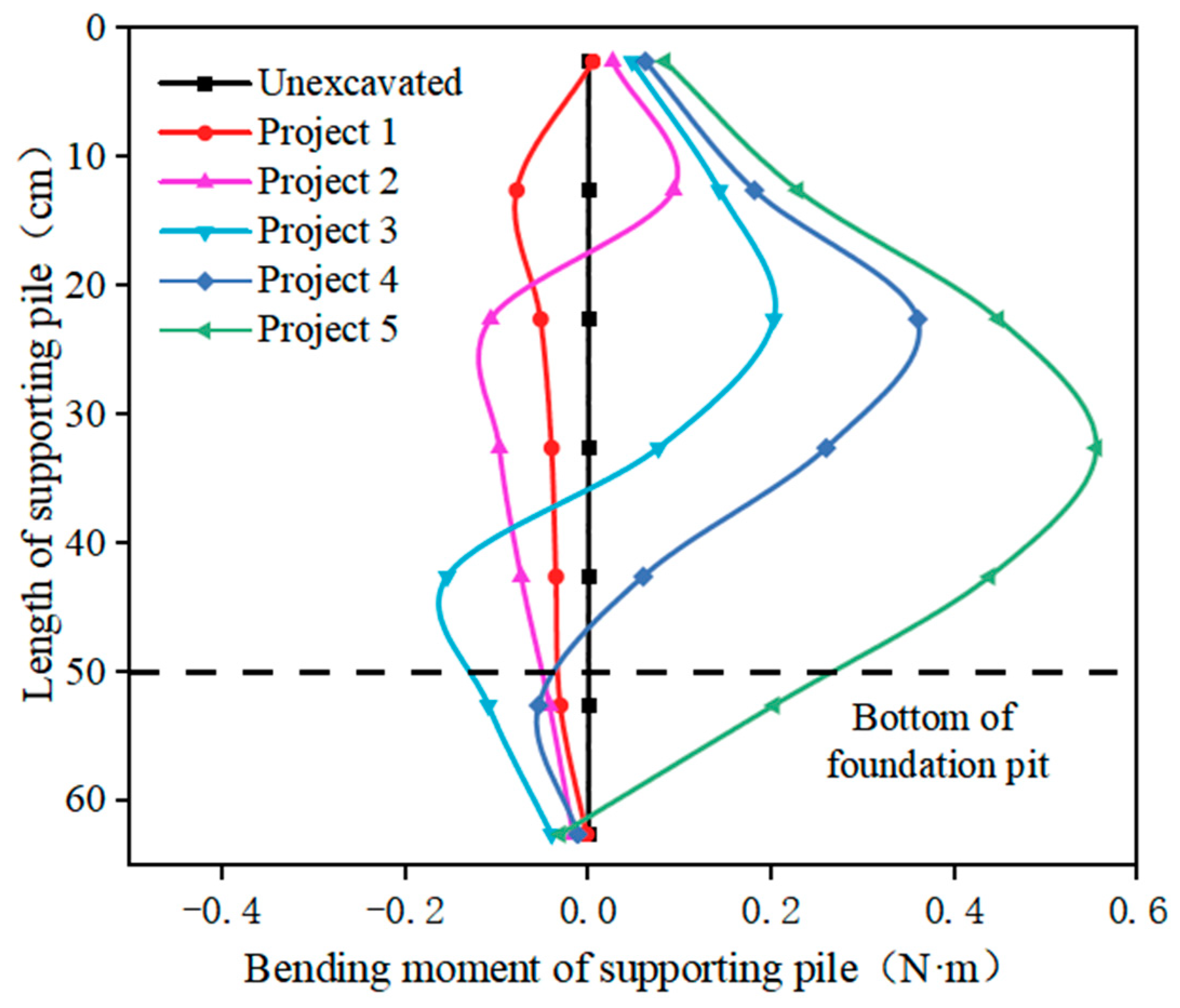
3.1. Analysis of Bending Moment of Supporting Pile

In the process of excavation, the central pile was selected to analyze its bending moment, and the measured strain data were obtained according to Formulas (10) and (11).
M = E I ( ε + + ε - ) / h
I = π ( D 4 - d 4 ) / 64
where M indicates the pile’s bending moment (N·m); E refers to the elastic modulus of the support pile (Pa); ε+, ε denote the strain data; h represents the strain gauge measurement point spacing (m); D, d signify the outer diameter and inner diameter of the support pile (m), respectively.
The bending moment variation curve of the central pile was obtained by processing the data, as presented in Figure 5:
Figure 5 suggests that the upper part of the supporting pile with the recyclable anchor rod support structure mainly bears a positive bending moment, while the lower part mainly bears a negative bending moment. The overall supporting pile presents a trend of a large middle bending moment and a small bending moment on both sides. With the deepening of excavation, the position of the reverse bending point of the supporting pile gradually declines. The overall supporting pile is a positive bending moment when the excavation reaches the design depth. The maximum bending moment reaches 0.56 N.
As a retaining structure, the retaining pile primarily withstands the external, active earth pressure exerted on the foundation pit. The anchor body transfers the load to the deep soil layer, thereby reducing the displacement and internal forces acting on the supporting pile and maintaining the stability of the foundation pit. At the early stage of excavation, the bending moment of the supporting pile changes slightly, owing to the small excavation depth. The bending moment value of the supporting pile increases with the increase in the excavation depth. The bending moment of the supporting pile decreases slightly near 10 cm. The reason for this phenomenon is that the prestressed anchor rod was installed at 10 cm. Under the action of the earthwork unloading, the prestressed anchor rod plays its role and generates the tension resisting the earth pressure behind the supporting pile, and the anchoring section of the recoverable anchor transmits the force into the soil and shares the effect of part of the earth pressure on the supporting pile, restricting the bending moment and deformation of the supporting pile and restricting the bending moment and deformation of the supporting pile. In the process of excavation, the maximum positive bending moment and a minimum negative bending moment of the supporting pile increased gradually, and the maximum bending moment value of the supporting pile was about 1/3 of the length of the pile. Moreover, the position of the maximum bending moment value of the supporting pile gradually declined with the deepening of the excavation. Two anchor rods were set in this supporting structure, equivalent to adding two elastic fulminations on the supporting pile. Therefore, the supporting pile exhibited an overall trend of an inverted S-shape change under the action of soil stress and the prestressed anchor rod.

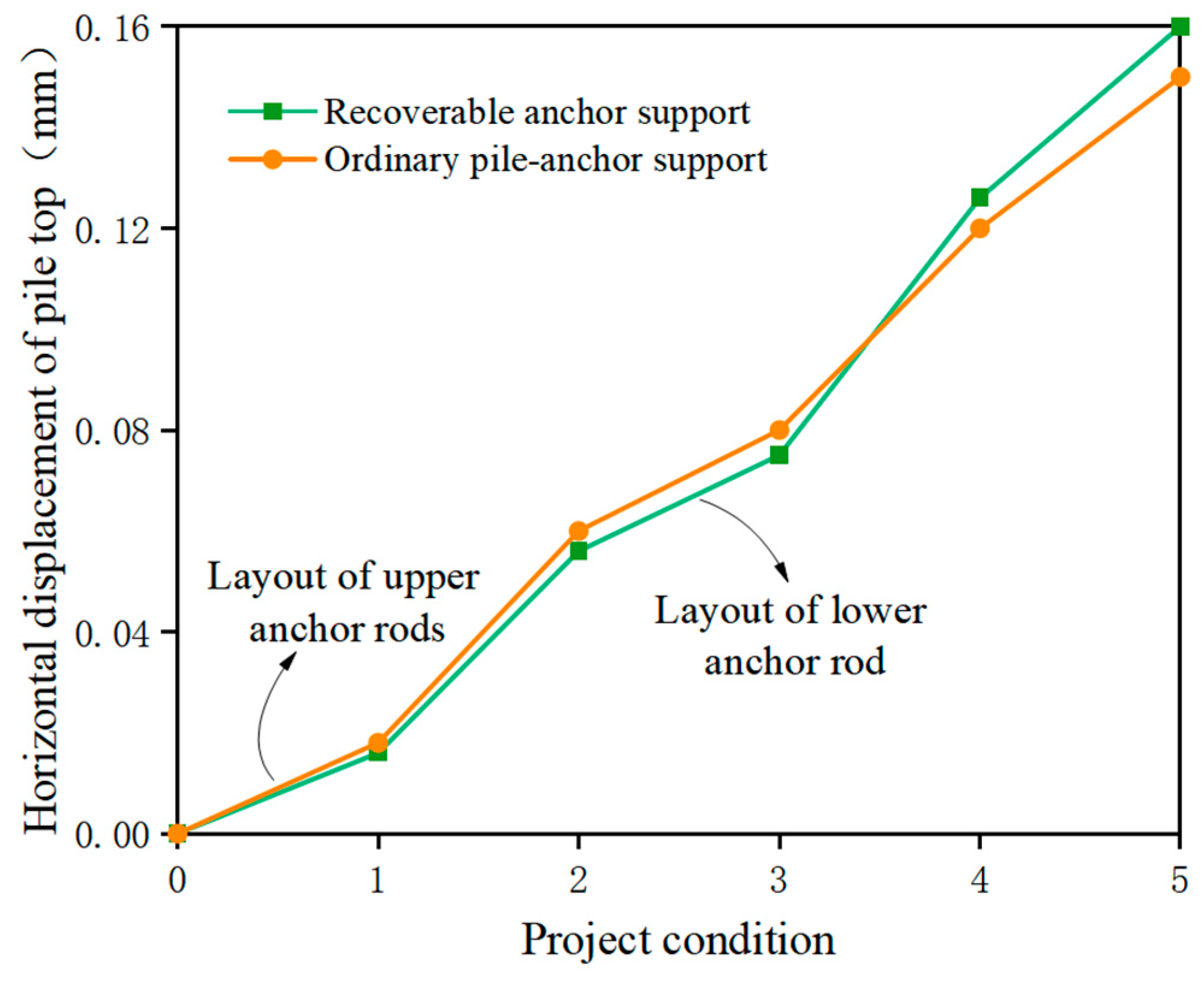
3.2. Horizontal Displacement of Pile Top

The changes in the pile top horizontal displacement during excavation are shown in Figure 6.
It can be observed in Figure 6 that the horizontal displacement of the pile top of the supporting structure using recycled anchor rods and the common pile–anchor rod support structure increases with the gradual excavation of the deep foundation pit. In the process of excavation, the displacement development of both structures is consistent.
The horizontal displacement of the pile top gradually increases. At the early stage of excavation, soil stress in the excavation area is redistributed due to the unloading of the soil mass in the excavation area, and active earth pressure is generated on the unexcavated side. Since the excavation depth is small in the early stage of excavation, the range of soil stress variation is not large, resulting in a small range of the horizontal displacement of the pile top in the early stage of excavation. With the continuous excavation of the foundation pit, the active earth pressure on the unexcavated side continuously increases, and the development of pile top horizontal displacement develops a positive correlation with the excavation depth. Furthermore, the change range of the horizontal displacement of the top of the supporting pile decreases when the excavation reaches the design depth. This is in that after the excavation reaches the design depth, the soil unloading is completed, the stress distribution tends to be stable, and the horizontal displacement of the top of the supporting pile begins to stabilize. The horizontal displacement of the top of the supporting pile reaches the maximum in project condition 5, with a maximum displacement of 0.15 mm.
Figure 7 exhibits the rates of change in the horizontal displacement of the pile top of the ordinary pile–anchor rod support structure and the support structure using recyclable anchor rods with the project condition. As suggested in Figure 7, the first recyclable anchor rod is laid at the excavation to 10 cm. After the excavation of the soil mass in the first layer, the anchor rod is prestressed by tightening the nut at the end of the excavation. The horizontal displacement of the pile top in project condition 1 is less than that in other project conditions. The second layer of the rock anchor rod does not play a role when the second layer of soil is excavated to the second layer of soil. Thus, the horizontal displacement of the pile top in project condition 2 is larger, and the growth rate is faster than that in project condition 1. Afterward, the foundation pit continues to excavate. When the excavation reaches 30 cm, the prestress is applied to the second layer of the rock anchor rod, and the second layer of the rock anchor rod plays a role in resisting part of the active earth pressure. The growth range of the pile top horizontal displacement in project conditions 1 and 3, corresponding to the effect of the anchor rod, is smaller than that in other project conditions. Therefore, the pile–anchor rod support structure with a recyclable anchor rod can effectively limit horizontal displacement during the excavation of the foundation pit.

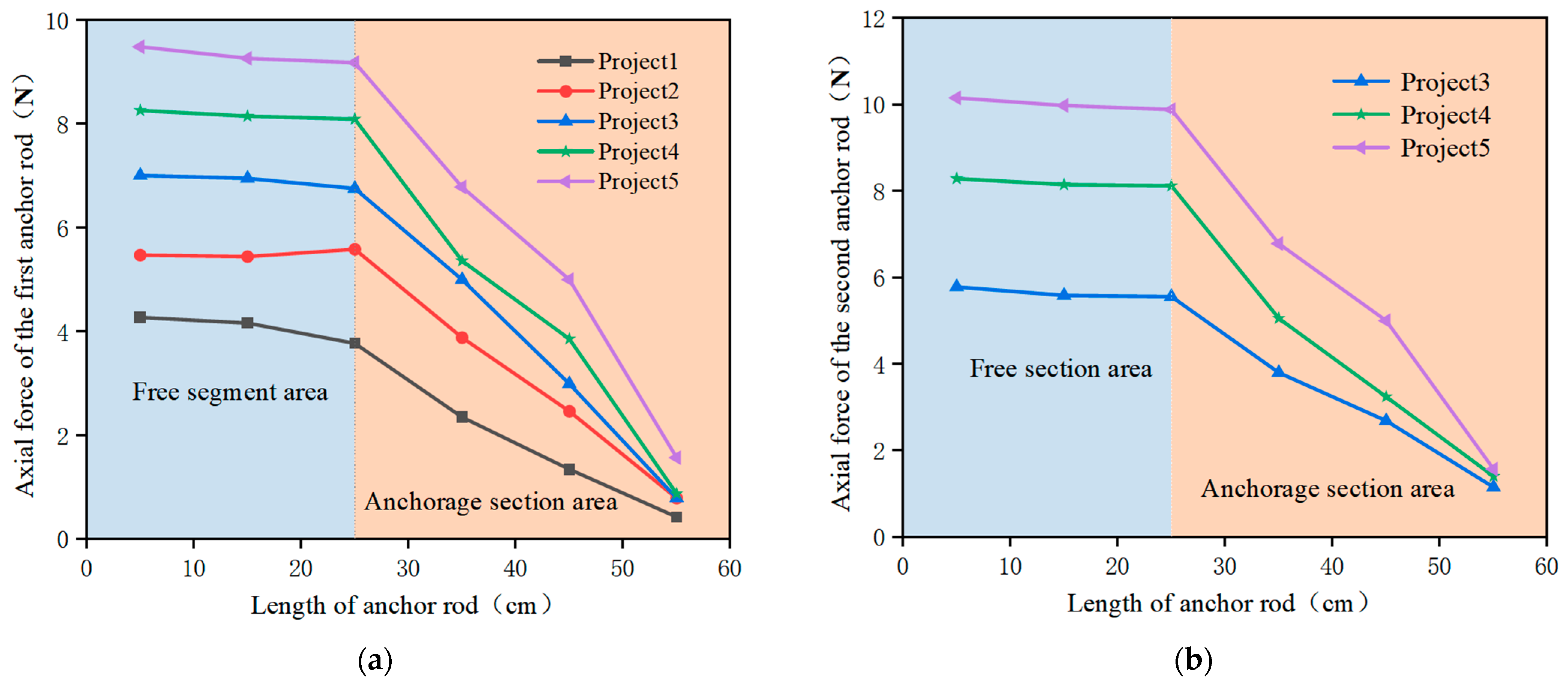
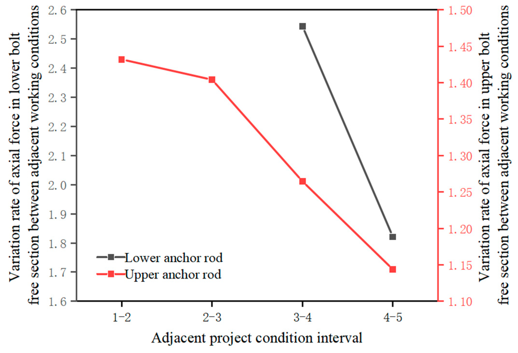
3.3. Axial Force of Anchor Rod

The measured strain data of the recyclable anchor rod can be calculated by Formula (12) to obtain the axial force value of the recyclable anchor rod.
F = E A ε i
where F represents the anchor rod axial force (N); E denotes the anchor rod elastic modulus (Pa); A refers to the cross-section area of the anchor rod (m2); εi indicates the axial strain at anchor rod i.
Two anchor rods are arranged in this supporting structure. The changes in the first anchor rod and the second anchor rod in the process of foundation pit excavation are exhibited in Figure 8.
The interaction between the supporting structure and earth pressure gradually appears with the gradual excavation of deep excavation and the laying of two recyclable anchor rods. In the process of foundation pit excavation, lateral displacement of the supporting piles emerges, which is attributed to earthwork excavation and unloading. The recyclable anchor rod is connected with the supporting pile as a whole through the waist beam, while the deformation and stress of the whole supporting structure impact each other. Figure 8a,b demonstrate that the variation trend of the recyclable anchor rod in the excavation process is similar to the trapezoid on the whole, and the development trend from the beginning end of the free section to the end of the anchor rod section presents a trend of attenuation. Moreover, the axial force of the free section of the recyclable anchor rod is larger than that of the anchor rod section on the whole, and the variation range of the axial force of the free section of the recyclable anchor rod is small and evenly distributed. Nonetheless, the axial force in the anchor rod section of the recyclable anchor rod decreases rapidly. This is because friction nails were added to the anchor rod section of the recyclable anchor rod to increase the anchor rod force, and part of the force in the anchor rod section of the anchor rod was transferred to the soil through the friction nails. As a result, the axial force in the anchor rod section of the anchor rod was less than that in the free section. The lower anchor rod bore the main tension when the excavation reaches project conditions 4 and 5. When the second anchor rod came into play, thus, the overall change trend of the first anchor rod increased, whereas the change rate between the two adjacent project conditions decreased. This is in that the two anchor rods cooperated to resist the soil pressure after the second anchor rod was laid.
In the process of excavation, the recyclable anchor rod is mainly under tension, and the axial force value of the anchor rod under each project condition increases with the excavation. The effect of the second anchor rod gradually appears with the arrangement of the second anchor rod and its function. The axial force of the lower anchor rod is higher than that of the upper anchor rod, and the axial force value of the two-layer anchor rod reaches the maximum after the excavation under project condition 5. In project condition 5, the horizontal displacement generated by the supporting pile is the maximum, and the corresponding project condition 5 has the maximum axial force of the anchor rod. Meanwhile, the maximum axial force of the upper anchor rod and lower anchor rod is 9.48 N and 10.15 N, respectively.
Figure 9 illustrates the change rate of the axial force in the free section of the recyclable anchor rod in two layers between adjacent project conditions.
Figure 9 implies that the change rate of axial force in the free section of the upper anchor rod in each project condition gradually decreases with the progress of excavation. The increase rate of axial force in the free section of the upper anchor rod in each project condition from excavation condition 1 to excavation condition 2 is 1.43, and the increase rate of axial force in the free section of the lower anchor rod decreases to 1.14 at the end of the excavation in project conditions 4 to 5. Since the soil pressure on the anchor rod increases accordingly, the axial force change rate of the lower anchor rod increases in each project condition.

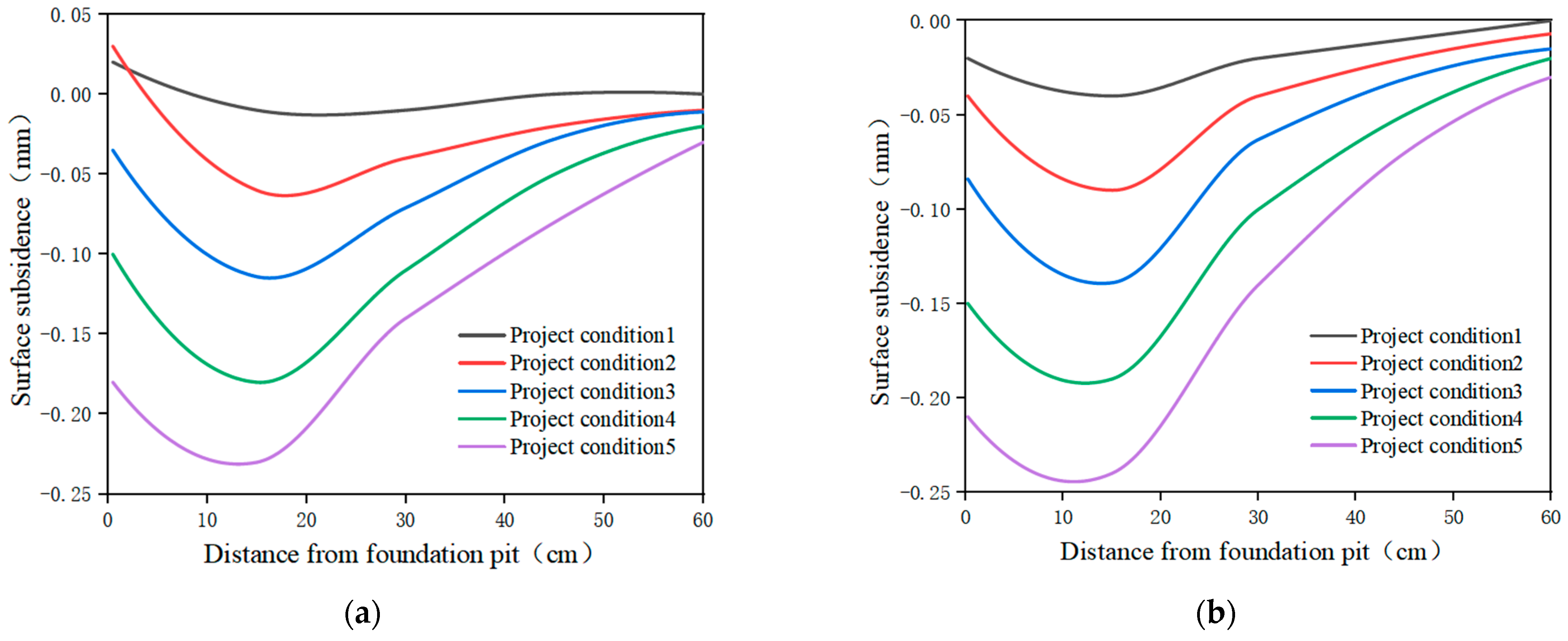
3.4. Surface Settlement

In the process of excavation, the external surface settlement of the foundation pit of the recyclable anchor rod support structure and the ordinary pile–anchor rod support structure is depicted in Figure 10.
It can be observed that the overall trend of the surface settlement of the ordinary pile–anchor rod support structures is consistent with that of recyclable anchor rod support structures. The peak value of the surface settlement of both is about −0.25 mm until the end of the excavation. Additionally, the support structure using a recyclable anchor rod achieves the same effect as that of an ordinary pile–anchor rod support structure. Furthermore, the limited displacement of some project conditions is better than that of ordinary pile–anchor rod support structures.
The excavation of the foundation pit is a process of soil unloading, which will cause the static balance of soil to be broken, the stress redistribution of the foundation’s pit soil, and thus the settlement of the surface outside the foundation pit. Figure 10 demonstrates that the excavation volume is small at the early stage of foundation pit excavation, resulting in a small amount of surface settlement. With the gradual deepening of excavation, the surface outside the foundation pit gradually increases, and different degrees of settlement appear at different positions from the edge of the foundation pit. Finally, the overall variation trend of the surface settlement is similar to that of the “spoon” shape.
At the early stage of foundation pit excavation, the displacement of the ordinary pile–anchor rod supporting structure is positive, leading to upward displacement. Nevertheless, the surface settlement of the recyclable anchor rod supporting structure is negative from the beginning because the constraint of the recyclable anchor rod on the supporting pile is not as good as that of the ordinary anchor rod. Therefore, the surface settlement of the ordinary pile–anchor rod supporting structure is positive at the early stage of excavation. The surface settlement increases as the excavation deepens. The surface settlement outside the foundation pit reaches its peak value when the excavation reaches the designed depth. The maximum value of the surface settlement outside the foundation pit emerges at a certain distance from the edge of the foundation pit. The monitoring of the surface settlement outside the foundation pit should be strengthened in practical engineering.

3.5. Analysis of Soil Pressure Results behind Piles in the Process of Foundation Pit Excavation

There is a dynamic change between the supporting structure and the soil mass in the process of excavation. The excavation and unloading of the soil mass provoke the displacement of the supporting pile. Consequently, the relative displacement between the supporting pile and the soil mass is behind the pile, and the stress of the soil mass behind the pile changes from the original static soil pressure to active soil pressure. The variation trend of the soil pressure behind the pile during excavation is drawn in Figure 11.
Figure 11 reflects that, under the combined action of a prestressed recyclable anchor rod and excavated soil, the soil pressure behind the pile is redistributed, and the soil pressure behind the pile has a non-linear change law as a whole. Moreover, the soil pressure behind the pile gradually increases along the depth direction. The change of the soil pressure value behind the pile is negatively correlated with the excavation depth with the development of various project conditions.
At the early stage of excavation, the soil load of the foundation pit is small, and the earth pressure begins to change from static earth pressure to the main earth pressure. The first anchor rod is laid at the excavation to 10 cm, and the prestress is applied. The anchor rod generates tension and drives the displacement of the supporting pile to the outside of the foundation pit. The soil pressure behind the pile presents a triangular distribution at the early stage of excavation and increases after continued excavation. At the end of the excavation in project condition 3, a second prestressed anchor rod is applied at a distance of 25 cm, with the same application law as that of the first layer. The soil pressure behind the pile decreases and continues to increase at the later stage of excavation, with the overall linear distribution similar to that of the pile.

3.6. Displacement Characteristics of Foundation Pit

Figure 12 depicts the trend of the foundation pit displacement before and after excavation. Observations reveal that the ground settlement continues to increase within 5 h after excavation; however, the growth rate is noticeably lower compared to the completion of the excavation. Eventually, the overall development reaches a state of stability. The horizontal displacement at the top of the pile follows a similar trend as the ground settlement, and the overall change becomes stable after the excavation of the foundation pit. It can be observed that the displacement of the recoverable anchor does not exhibit remarkable increases for a period of time after excavation.

3.7. Foundation Pit Backfilling Analysis

3.7.1. Analysis of Surface Settlement Results in the Backfilling Process

The change of the surface settlement in the recovery period is illustrated in Figure 13.
Figure 13 demonstrates little difference between the surface settlement of the first layer and that of the last excavation condition when the first layer is backfilled. The maximum surface settlement after the first layer is finished is −0.39 mm, and the surface settlement changes from −0.39 mm to −0.40 mm when the backfilling reaches 30 cm. Thus, there is little change in land subsidence. When the lower anchor rod is recovered, the change of the surface settlement noticeably increases compared with the previous two project conditions, and the maximum surface settlement is −0.46 mm. Simultaneously, the lower waist beam is backfilled, the anchor rod is recovered, and the original two-fulcrum pile–anchor rod supporting structure is altered into a single-fulcrum pile–anchor rod supporting structure. Therefore, the maximum surface settlement changes the most under this project condition. Compared with the previous project condition, the increase is 0.06 mm, which is six times the increase of the previous project condition. The backfill continues after the recovery of the lower anchor rod. During this period, the surface settlement increases by 0.02 mm, the backfill reaches the top of the pit, and the upper anchor rod is recovered. The maximum surface settlement is −0.50 mm.

3.7.2. Analysis of Horizontal Displacement of Pile Top in the Backfilling Process

Backfilling is divided into five stages at an interval of 10 cm. The changes in the horizontal displacement of the pile top are drawn in Figure 14.
In the process of foundation pit backfilling, the horizontal displacement of the pile top still increases and moves towards the pit. The horizontal displacement of the pile top is 0.16 mm and 0.18 mm after backfilling the first and second layers of soil, respectively. The earth pressure generated by backfilling the soil twice offsets the active earth pressure on the excavated side. As a result, the change in the horizontal displacement of the pile top is small. When the third layer of soil is backfilled, the anchor rod is recycled. At this stage, the horizontal displacement of the pile top increases rapidly, and the horizontal displacement of the pile top is 0.22 mm, which is 200% of the previous project condition. Meanwhile, the soil stress of the foundation pit changes owing to the small backfill depth and the failure of the anchor rod pull-out. Moreover, the active earth pressure of the foundation pit is greater than the passive earth pressure. Consequently, the supporting pile moves into the pit. When the fourth layer is backfilled, the horizontal displacement of the pile top decreases, and it is pulled out at the waist beam.

4. Conclusions

In this study, a model test was conducted to analyze the stress and displacement of the recyclable anchor rod support structure. The conclusions drawn were as follows.
(1)
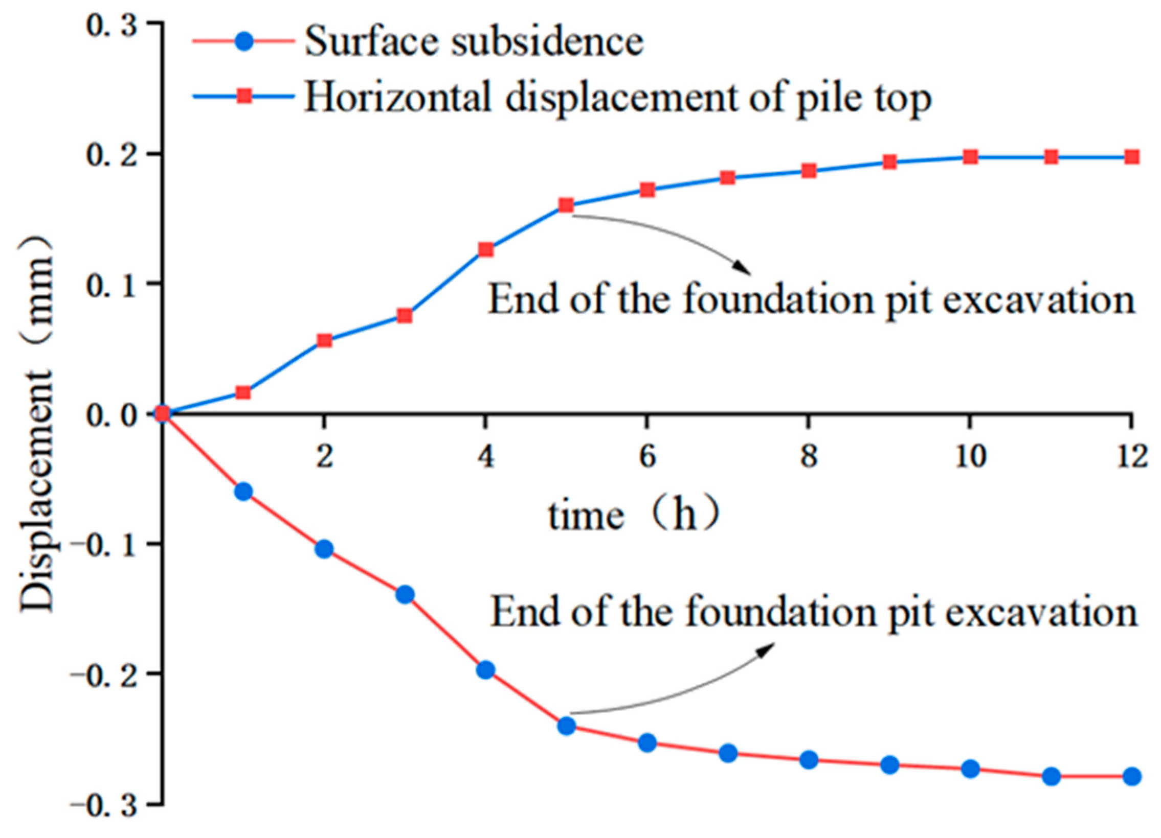
During the excavation process, the horizontal displacement of the pile top of the recoverable anchor-supporting structure exhibits a gradual upward trend. However, the rate of displacement increase at the pile top is comparatively lower under working conditions 1 and 3 compared to the other conditions. Moreover, a notable reduction in the bending moment of the supporting pile is observed around the lengths of 10 cm and 30 cm, which shows that the recoverable anchor can effectively limit the horizontal displacement of the top of the supporting pile.
(2)
The ground settlement of the common pile–anchor-supporting structure exhibits positive values in working condition 1 and negative in working condition 2. In contrast, the ground settlement of the recoverable anchor-supporting structure is consistently negative throughout. After excavation, the maximum ground settlement observed in the foundation pit with a recoverable anchor is 0.05% of the excavation depth.
(3)
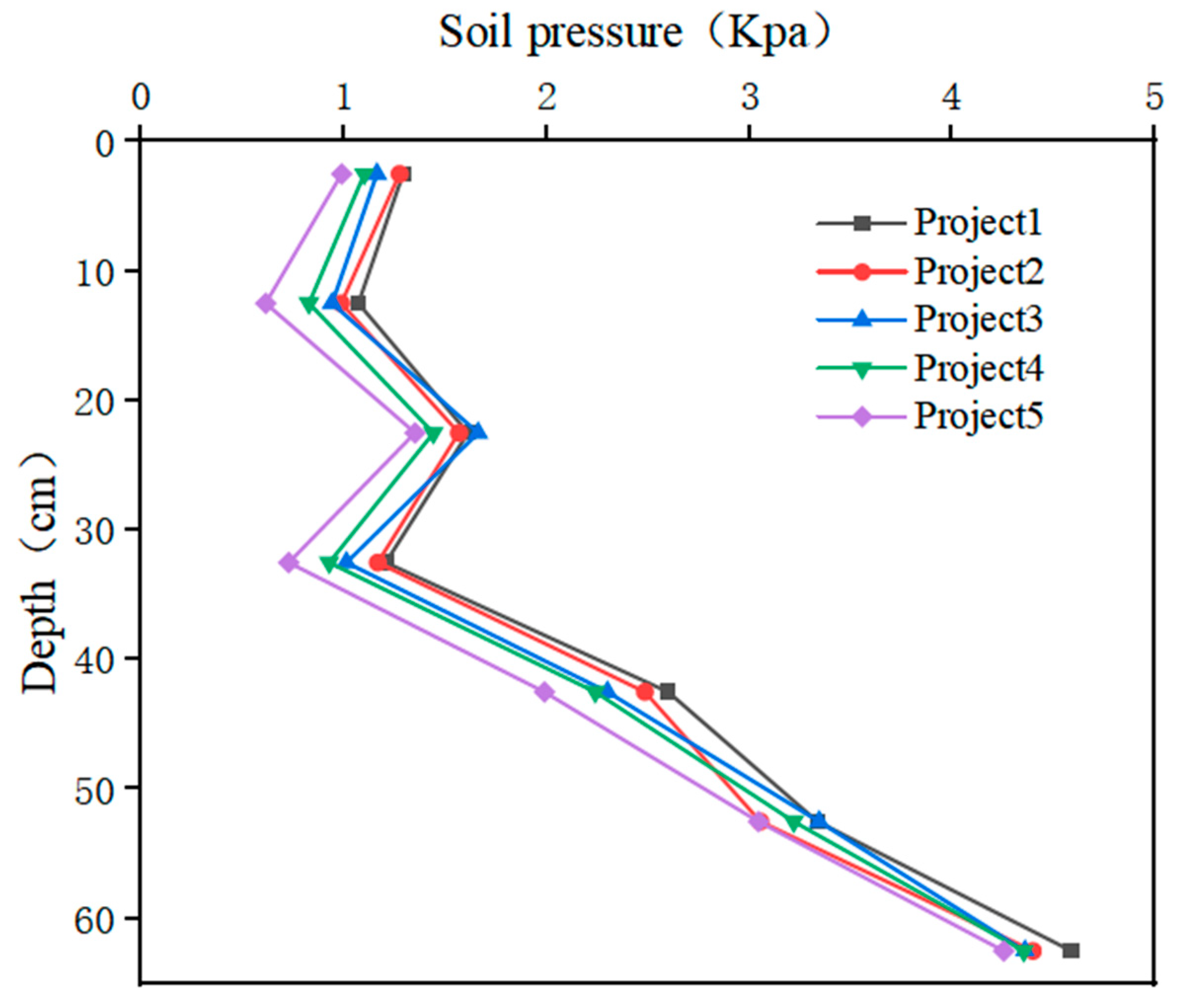
The earth pressure distribution of the recoverable anchor-supporting structure exhibits a non-linear pattern. Initially, the earth’s pressure decreases, followed by a distinctive “R” shape distribution. Additionally, there is a positive correlation between the earth pressure distribution and the depth of excavation.
(4)
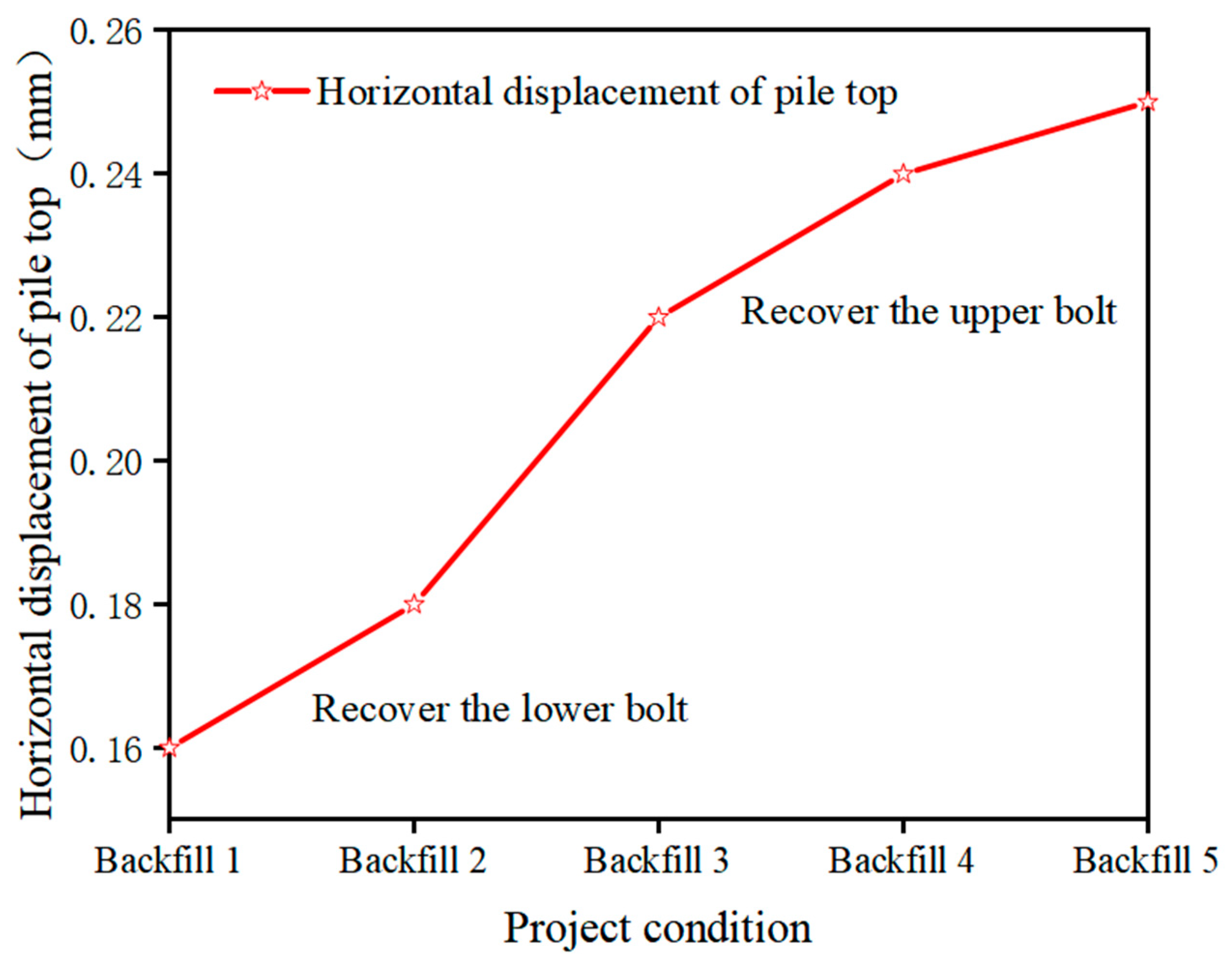
In the backfilling stage, both the horizontal displacement of the pile top and the surface settlement exhibit a progressive increase as the working conditions change. The surface settlement experiences the most significant increase when the anchor rod is pulled out from the lower layer, eventually reaching a state of relative stability. The maximum settlement recorded is 0.1% of the excavation depth. Therefore, it is necessary to increase the strength of the waist beam and the thickness of the shotcrete at the position of the lower anchor when the anchor is recovered. Furthermore, it is crucial to enhance monitoring efforts.

Author Contributions

Conceptualization, S.Z. and S.F.; methodology, S.F., C.D. and Q.X.; validation, S.Z., S.F. and C.D.; formal analysis, S.F.; investigation, S.F.; resources, S.Z.; data curation, S.F.; writing—original draft preparation, S.F.; writing—review and editing, S.Z. and S.F.; supervision, S.Z.; project administration, Z.K.; funding acquisition, Z.K. All authors have read and agreed to the published version of the manuscript.

Funding

This work was Supported by Open Research Fund of Anhui Province Key Laboratory of Green Building and Assembly Construction, Anhui Institute of Building Research & Design, Grant NO. 2022-JKYL-006.

Institutional Review Board Statement

Not applicable.

Informed Consent Statement

Not applicable.

Data Availability Statement

Data will be available on request.

Acknowledgments

Supported by Open Research Fund of Anhui Province Key Laboratory of Green Building and Assembly Construction, Anhui Institute of Building Research & Design, Grant NO. 2022-JKYL-006.

Conflicts of Interest

The authors declare no conflict of interest.

References

  1. Feng, Z.; Li, D. Study on safety optimization of embedded ratio of deep foundation pit support in sandy pebble. China Saf. Sci. J. 2021, 31, 125–131. [Google Scholar]
  2. Zhou, A.; Wang, B.; Li, J.; Zhou, X.; Xia, W. Long-term stability analysis and deformation prediction of soft soil foundation pit in Taihu Tunnel. J. Zhejiang Univ. Eng. Ed. 2022, 56, 692–701. [Google Scholar]
  3. Zheng, G.; Zhu, H.; Liu, X.; Yang, G. Foundation pit engineering and underground engineering safety and environmental impact control. J. Civ. Eng. 2016, 49, 1–24. [Google Scholar]
  4. Zhang, Q.; Liang, D.; Xu, C. Application of pile-anchor rod supporting structure in backfill area. J. Geotech. Eng. 2012, 34, 358–363. [Google Scholar]
  5. Li, M.; Chen, Q.; Zhao, X. Application of pile-anchor rod supporting technology in deep foundation pit engineering. Build. Struct. 2020, 50, 789–792. [Google Scholar]
  6. Peng, Y. Construction Design of Pile Anchor rod Support in Deep Foundation Pit Excavation. Int. J. Multiphysics 2021, 15, 19–28. [Google Scholar]
  7. Gang, L.; Huang, B. Analysis of deformation characteristics of adjacent buildings caused by deep foundation pit excavation with pile-anchor rod support. Constr. Technol. 2017, 46, 54–57. [Google Scholar]
  8. Liu, C.; Zhang, Z.; Lou, H.; Kuang, S. Application of prefabricated foundation pit supporting structure in Guangzhou. Geotech. Found. 2007, 4, 28–30. [Google Scholar]
  9. Fu, W.; Zou, J.; Huang, K. Research summary of recyclable anchor rod technology. Chin. J. Undergr. Space Eng. 2021, 17, 512–522, 528. [Google Scholar]
  10. Wu, R.; Xu, J.; Zhou, B.; Wang, Q. Development and application of new recyclable resin metal anchor rod. Min. Mach. 2011, 39, 19–22. [Google Scholar]
  11. Wei, Y. Analysis of the influence of foundation pit excavation on the surrounding environment. J. Lanzhou Univ. Technol. 2022, 48, 136–144. [Google Scholar]
  12. Jin, J.; Du, H.; Zhang, Z.; Guo, Y.; Song, W. Analysis of pile-anchor rod soil nailing composite support in complex environment. J. Shenyang Jianzhu Univ. Nat. Sci. Ed. 2017, 33, 613–620. [Google Scholar]
  13. Zhang, B.; Huang, X.; Song, N. Analysis of anchor rod rod (cable) of pile-anchor rod supporting structure in deep foundation pit. Sichuan Build. Sci. Res. 2015, 41, 168–171. [Google Scholar]
  14. Ma, J. Application of recyclable spin soil nail anchor rod pipe in Xi ‘an Metro Line 4. Road Mach. Constr. Mech. 2017, 34, 80–83. [Google Scholar]
  15. Gong, X.; Yu, J. Development and prospect of recyclable anchor rod technology. J. Civ. Eng. 2021, 54, 90–96. [Google Scholar]
  16. Du, C.; Xiao, T.; He, Y.; Yang, X. Experimental and Numerical Studies on the Inflatable Recyclable Anchor rod in the Tube Piece Type Based on the Soil-Anchor rod Interaction Mechanism. Adv. Civ. Eng. 2021, 2021, 8866211. [Google Scholar]
  17. Chen, Z.; Xiang, J.; Ding, W. Numerical analysis of mechanical properties of large diameter recyclable anchor rod. J. Geotech. Eng. 2012, 34, 172–176. [Google Scholar]
  18. Yu, L.; Yu, Z.; Wang, W.; Han, Z.; Zhao, T. Stress and deformation analysis of assembled recyclable support and pile-anchor rod support structure for foundation pit. J. Jilin Univ. Earth Sci. Ed. 2021, 51, 1789–1800. [Google Scholar]
  19. Liu, G.; Lian, B. Proposal and experimental study of the expanded anchor rod structure with recyclable fast anchor rod. J. Earthq. Eng. 2022, 44, 551–557. [Google Scholar]
  20. Li, H.; Zhang, K. Application of recyclable anchor rod in foundation pit supporting engineering. J. Build Struct. 2019, 49, 110–114+21. [Google Scholar]
  21. Zheng, Q.; Zhang, X.; Liu, J.; Liu, Y.; He, D.; Wang, Y.; Feng, X. Mechanical properties of foundation pits and basements during pile-anchor rod recovery. J. Jinan Univ. Nat. Sci. Ed. 2022, 36, 16–20. [Google Scholar]
  22. Liu, W.; Ge, M.; Wan, J.; Yu, L.; Hai, J. Numerical analysis of deformation characteristics and influencing factors of deep and large foundation pit supported by pile-anchor rod considering spatial effect. J. Railw. Sci. Eng. 2021, 18, 3188–3200. [Google Scholar]
  23. Li, J.; Li, L. Numerical Analysis on a New Pressure-Type Anchor Rod Cable with Precast Anchor Rod Head Based on FLAC3d: 2nd International Conference on Electronics. Network and Computer Engineering (ICENCE 2016); Atlantis Press: Amsterdam, The Netherlands, 2016. [Google Scholar]
  24. Craig, W.H. Simulation of foundations for offshore structures using centrifuge modelling. In Developments in Soil Mechanics and Foundation Engineering: Model Studies; Applied Science Publisher: London, UK, 1983. [Google Scholar]
  25. GB 50123-2019; Standard for Soil Method. Ministry of Housing and Urban-Rural Development of the People’s Republic of China (MOHURD): Beijing, China, 2019.
  26. Zhou, S.; Zhang, Y.; Li, Q.; Li, D.; Wang, W.; Shi, M.; Chen, W. An Externally Installed Friction Nail Recyclable Anchor Rod. Patent CN111075486B, 15 June 2021. [Google Scholar]
Figure 1. Grading curve of sandy soil for test.
Applsci 13 07713 g001
Figure 2. Model test diagram used in experiments.
Applsci 13 07713 g002
Figure 3. Model of anchor rod. (a) Common pile–anchor rod; (b) recoverable pile–anchor rod.
Applsci 13 07713 g003
Figure 4. Layout of measuring points.
Applsci 13 07713 g004
Figure 5. Bending moment curves of supporting pile.
Applsci 13 07713 g005
Figure 6. Horizontal displacement variation curve of pile top.
Applsci 13 07713 g006
Figure 7. Variation of horizontal displacement of pile top.
Applsci 13 07713 g007
Figure 8. Anchor rod axial diagram. (a) Axial diagram of the first anchor rod; (b) axial diagram of the second anchor rod.
Applsci 13 07713 g008
Figure 9. Axial force variation rates of the bolt in the free section.
Applsci 13 07713 g009
Figure 10. Surface settlement under different bolt systems. (a) Surface settlement map of an ordinary pile–anchor support structure; (b) surface settlement map of recyclable bolt support structure.
Applsci 13 07713 g010
Figure 11. Distribution curve of earth pressure behind the pile.
Applsci 13 07713 g011
Figure 12. Displacement–time relation curve.
Applsci 13 07713 g012
Figure 13. Surface settlement variation curve in the backfilling process.
Applsci 13 07713 g013
Figure 14. Curve of horizontal displacement of the roof.
Applsci 13 07713 g014
Table 1. Model test similarity ratio.
ParametersPrototypeModelSimilarity Ratio
Foundation pit depth/m12.50.525
support pile length/m160.6524.62
support pile diameter/m0.80.03225
anchor length/m160.6026.67
support pile elastic modulus/GPa302.8510.53
anchor elastic modulus/GPa2108.3526
Table 2. Parameter table of project conditions.
Project ConditionTypeAnchor RodDepth (cm)
1Excavation and laying of an anchor rodAnchor rod 110.00
2Excavation 20.00
3Excavation and laying of an anchor rodAnchor rod 230.00
4Excavation 40.00
5Excavation 50.00
Disclaimer/Publisher’s Note: The statements, opinions and data contained in all publications are solely those of the individual author(s) and contributor(s) and not of MDPI and/or the editor(s). MDPI and/or the editor(s) disclaim responsibility for any injury to people or property resulting from any ideas, methods, instructions or products referred to in the content.

