Article

Experimental Study on Femtosecond Laser Processing Performance of Single-Crystal Silicon Carbide

School of Mechanical and Electronic Engineering, Shandong Jianzhu University, Jinan 250101, China
*
Author to whom correspondence should be addressed.
Appl. Sci. 2023, 13(13), 7533; https://doi.org/10.3390/app13137533
Submission received: 8 May 2023 / Revised: 25 May 2023 / Accepted: 14 June 2023 / Published: 26 June 2023
(This article belongs to the Special Issue Advances in Additive Manufacturing and Laser Processing)

Abstract

:
Femtosecond laser processing technology offers a promising technique for the preparation of micro and nanostructures of single-crystal silicon carbide (SiC), thanks to its high precision and non-destructive processing. However, further research is needed to optimize processing parameters, as well as improve efficiency and quality of the process. This study conducts experiments to explore the effects of femtosecond laser ablation on single-crystal SiC. The influence and significance of parameters, such as fluence (F), repetition rate, scan speed (S), multipass scanning (c) and numerical aperture on the performance of grooves, including groove depth, groove width, heat-affected zone (HAZ) width, material removal rate (MRR) and side wall inclination angle, were studied. The results show that the influence of fluence and numerical aperture on groove depth, groove width, HAZ width, MRR and side wall inclination angle is very significant. The scan speed has a very significant effect on the groove depth, groove width, HAZ width and side wall inclination angle but has insignificant effect on the MRR. Repetition rate and multipass scanning have a very significant effect on groove depth, HAZ width, MRR and side wall inclination angle and a moderately significant effect on groove width. The experimental methods of increasing the aspect ratio and reducing the HAZ width were studied, and a significance analysis was carried out. Fluence, multipass scanning and z-layer feed have significant effects on groove depth, groove width, aspect ratio, HAZ width and MRR. The influence of polarization angle on groove depth, groove width, aspect ratio and MRR is insignificant.

1. Introduction

Single-crystal SiC possesses many advantages, including outstanding optical properties, excellent thermal stability, high chemical inertia and high hardness. Owing to these features, it finds widespread applications in various fields, such as integrated circuits, solar cells and photoelectric detection, among others [1]. Fabricating micro/nanostructures on the surface of single-crystal SiC using traditional manufacturing technologies is challenging due to its difficult-to-machine property. However, femtosecond laser technology offers a powerful solution for the micro/nano fabrication of SiC materials. This method has advantages, such as high 3D-precision and non-invasive manufacturing characteristics [2]. The femtosecond laser processing technology, which has the advantages of three-dimensional high-precision and non-destructive processing, provides a technical means for the preparation of micro/nanostructures of single-crystal SiC [3,4]. Based on the characteristics and application requirements of femtosecond laser machining, many scholars have conducted experimental research on femtosecond laser micro-machining [5,6].
To fabricate grooves or ablation craters with low thermal damage, high aspect ratio, and MRR, commonly used methods include changing the processing environment or adjusting laser parameters, such as liquid assisted processing, selective chemical etching assisted processing and the temporal and spatial modulation of the beam. When machining grooves are fabricated in an ambient environment, the depth of material removal is mainly controlled via the optical penetration depth within the low fluence range [7]. With the increase in fluence and its pulse number, the interaction between pulses increases the absorption of materials to subsequent pulses, and the effect of heat accumulation on material removal cannot be ignored. However, cracks, fragments and recast layers appeared around the ablation crater [8]. In addition, pulse width and wavelength also have a certain impact on material ablation [9,10]. When the pulse width is narrower and the peak fluence is higher, the enhanced ultrafast absorption of laser energy by the material is stronger, resulting in an increase in ablation depth. However, when the pulse width decreases to a certain value, the further reduction of the pulse width will lead to an increase in threshold fluence and the width of the groove will not change with the change of pulse width. When the laser wavelength is shorter and the photon energy is greater, the processing accuracy will be higher, the ablation depth will be greater and the ablation threshold will be lower [10].
In order to eliminate the recast layer and thermal damage introduced by femtosecond laser processing in the air environment, many scholars have adopted liquid assisted methods. The flow and volatilization of ethanol help further carry away the ablative debris, reduce the redeposition of ablative materials and facilitate the discharge of debris from the crater [11]. The ablation depth of ethanol assisted lithography is deeper than that of processing in ambient air, and ethanol-assisted lithography does not generate additional thermal damage around the crater. Distilled water assistance is also commonly used in the preparation of high surface quality grooves [12]. The underwater femtosecond laser processing method can effectively reduce the redeposition of debris in the surrounding area of the groove, thereby improving the processing quality. However, the uncertainty of laser-induced bubbles and material deposition limits the surface accuracy and processing efficiency of grooves. Zheng et al. [13] observed the femtosecond laser processing of underwater SiC ceramics using a high-speed camera and found that the disturbance degree of laser induced bubbles is closely related to the size, distribution and motion of the bubbles. When small bubbles aggregate into large bubbles and adhere to the bottom or side wall of the groove, it greatly affects the reflection, refraction and scattering of the laser beam.
Due to the limitations of underwater processing, many scholars have combined femtosecond laser processing with selective chemical etching methods to process SiC. After processing the surface of the workpiece material with femtosecond laser, a mixture of hydrofluoric acid and nitric acid is used for the selective chemical etching of the laser modified area. Craters can be fabricated on the workpiece material, and the chemical composition around the craters is the same as that of the unprocessed surface, without introducing impurities [14]. In addition to craters, grating structures can also be prepared on the surface of workpiece materials using femtosecond laser processing combined with chemical etching methods [15].
Changing the characteristics of the laser beam is also a commonly used measure to improve the processing effect. To improve processing efficiency and consistency, a diffractive optical element is used to divide a laser beam into five laser beams [16]. A single scan can obtain five uniform laser induced modified regions with similar morphology. Then, the materials of these modified regions are etched with hydrofluoric acid to form a micro-groove array, which increases processing efficiency by five times and obtains high aspect ratio grooves. In addition, when the laser intensity is higher than the ablation level, the Gaussian beam will be nonlinear distortion, and the Bessel beam can resist this instability. Therefore, Bessel beams are more suitable for groove machining with high aspect ratios [17].
The changes in the processing environment also have a significant impact. When the ambient pressure drops, the ionization effect of the air weakens, the depth of erosion increases and the sediment around the erosion crater is less [18]. When using etching gas and nitrogen gas for material processing, rough surface quality can be formed on the material, while in a vacuum environment, relatively good surface quality can be obtained [19]. As the ambient pressure increases, the collision between plasmas increases, resulting in an increase in energy reaching the material surface and an increase in ablation depth. However, the number of splashes on the sample surface increases. When the environmental pressure continues to increase, due to the obstruction of environmental gases and dense plasma, the processing depth decreases and the splashes on the surface of the workpiece will decrease [20].
In order to further understand the femtosecond laser processing performance of single-crystal silicon carbide and obtain a low thermal damage, high aspect ratio and high MRR, it is essential to conduct experiments on the femtosecond laser processing of silicon carbide micro-grooves. Hence, in the present study, experimental research was conducted on the feasibility of femtosecond laser processing of single-crystal SiC. Based on previous research [21,22], this paper conducts single factor experiments and significance analysis to investigate the femtosecond laser processing of grooves of SiC. The effects of laser parameters, such as laser fluence, scan speed, repetition rate and multi-pass scanning on the depth, width, HAZ width and side wall inclination angle of the grooves, are discussed. Experimental methods for improving the aspect ratio and surface quality of grooves are discussed and the significance of the experimental results is analyzed.

2. Materials and Methods

The femtosecond laser micro-processing system employed in the experiment can emit a collimated beam with a wavelength of 800 nm, a pulse width of 35 fs, maximum single pulse energy of 13 mJ and a maximum repetition rate of 1 kHz. The laser beam is horizontally linearly polarized, and the pulse energy approximately follows a Gaussian distribution. The diameter of the laser beam before focusing is 12 mm. After focusing the laser beam through a 20 × 0.4 long-focus objective lens, the spot diameter is 36.63 μm. The sample used in this experiment is N-type 4H single-crystal SiC, with a diameter of 50 mm and a thickness of 350 µm. Before laser processing, the workpiece was ultrasonically cleaned with ethanol and distilled water for 15 min. After cleaning, it was installed on an X-Y workbench, and the experiment was conducted in ambient air. After the experiment, the depth, width, HAZ width and side wall inclination angle of the grooves were observed via laser microscope. The surface morphology was observed using scanning electron microscopy.
Figure 1 shows the machined surface morphology of the groove. The groove depth, groove width, HAZ width, side wall inclination angle and cross-sectional area can be observed and measured under the laser microscope. MRR is equal to the scan speed multiplied by the cross-sectional area.
Table 1 contains two single factor experimental schemes. Experiment 1 was used to analyze the significance of the influence of process parameters on the machined surface morphology (groove depth, groove width, HAZ width and side wall inclination angle) and MRR. Each group of experiments was repeated three times. For each group of experiments, the magnification of a long focal length objective lens is 20 and 60, respectively, and the numerical aperture NA is 0.4 and 0.6, respectively. A total of 25 experiments were conducted, with each experiment repeated three times.
Experiment 2 shows a single factor experimental scheme, with each experiment repeated three times using a long focal length of 20 × 0.4 objective lens processing. The morphology of the grooves after processing was observed using confocal laser microscopy and scanning electron microscopy. Use a half-wave plate to adjust the polarization (E, electric field) direction of the laser beam to be parallel to the scanning direction (polarization angle 0°) or perpendicular to the scanning direction (polarization angle 90°). As shown in Figure 2, when machining layer by layer along the z-direction (referred to as z-layer feeding), the total feed rate of the laser beam in the depth direction remains at 30 µm. The purpose of this experiment is to design experimental parameters according to the previous single factor experiment, so as to obtain grooves with larger aspect ratio and smaller HAZ width.

3. Results and Discussions

3.1. Significance Analysis

Table 2 shows variance analysis results of the groove depth D, groove width W, MRR, HAZ width and side wall inclination angle θ. The influence of fluence and numerical aperture on groove depth, groove width, HAZ width, MRR and side wall inclination angle is very significant. The scan speed has a very significant effect on the groove depth, groove width, HAZ width and side wall inclination angle but has an insignificant effect on the MRR. Repetition rate and multipass scanning have a very significant effect on groove depth, HAZ width, MRR and side wall inclination angle, and a moderately significant effect on groove width. The effect of scan speed on MRR is insignificant, while the effect of repetition rate on groove width is moderately significant.
The femtosecond laser processing of silicon carbide grooves is mainly used for micro-cavities, micro-mechanical systems, water droplet based micro-fluidic devices, micro-fluidic sensors and biosensors. Grooves with high aspect ratio, high MRR and small HAZ width help reduce friction in micro-fluidic devices and improve flow ability. A larger scan speed has insignificant impact on MRR, while a smaller scan speed has a very significant impact on MRR. A smaller number of multipass scanning has a moderately significant impact on groove width, while a larger number of multipass scanning has a very significant impact on groove width. In order to inject more laser energy into the workpiece, a smaller scanning speed and larger number of multipass scanning were used in Experiment 2. Table 3 shows the variance analysis results of groove depth, groove width, MRR, HAZ width and aspect ratio. The fluence, multipass scanning, scan speed and z-layer feed all have a significant impact on the machining characteristics. The polarization angle only has a significant effect on the HAZ width but has insignificant effect on the groove depth, groove width, aspect ratio and MRR.

3.2. Experimental Results

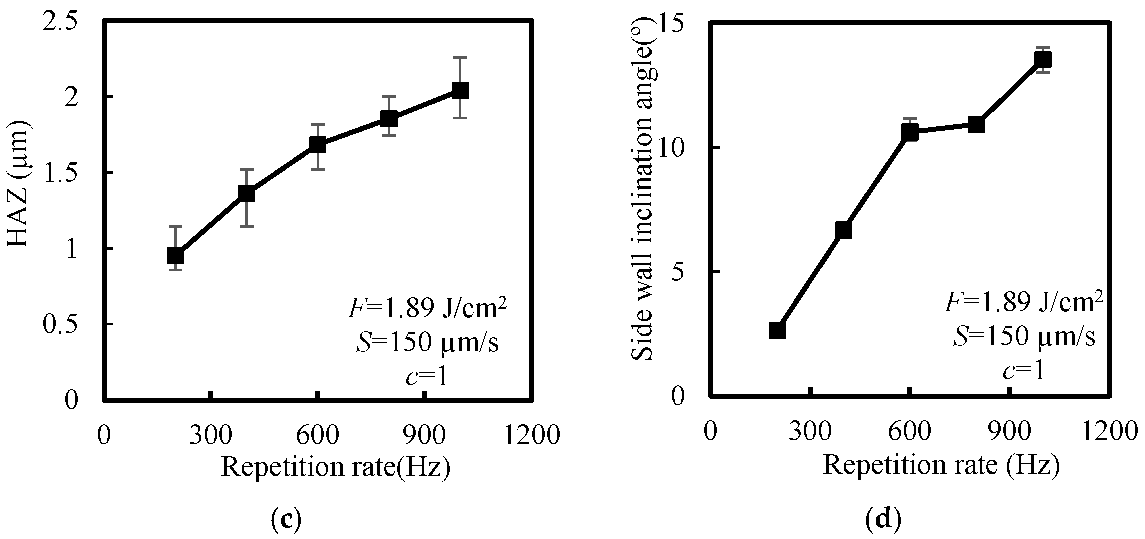
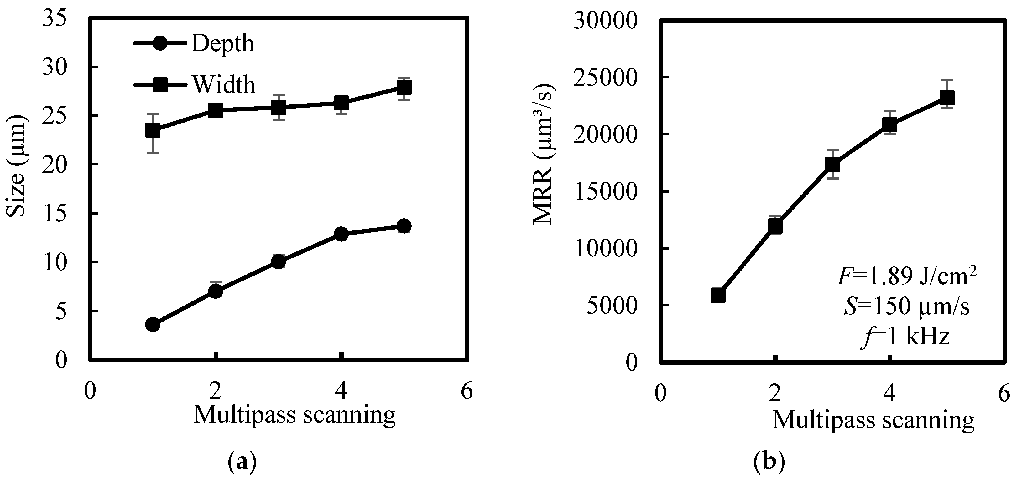
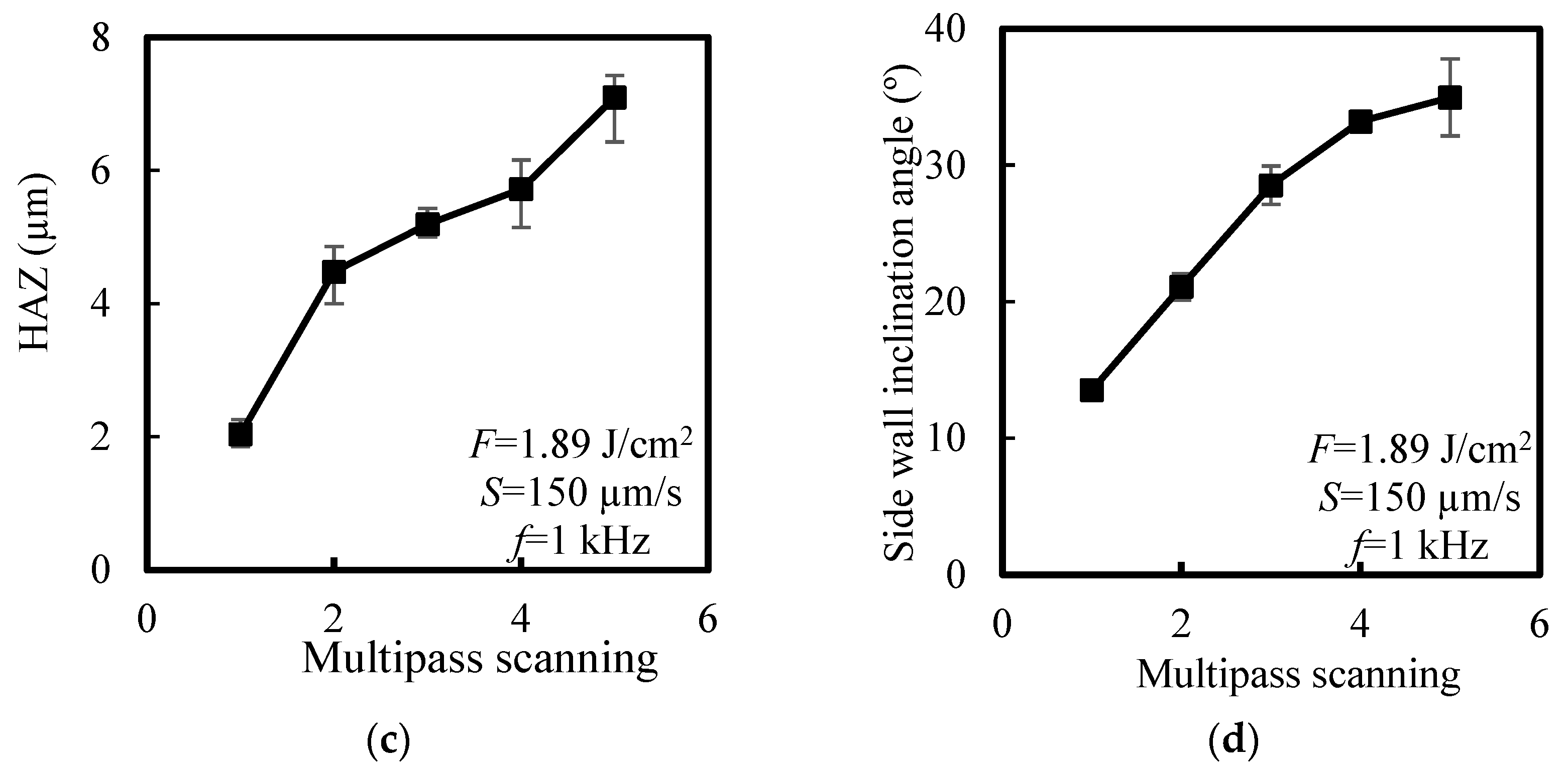
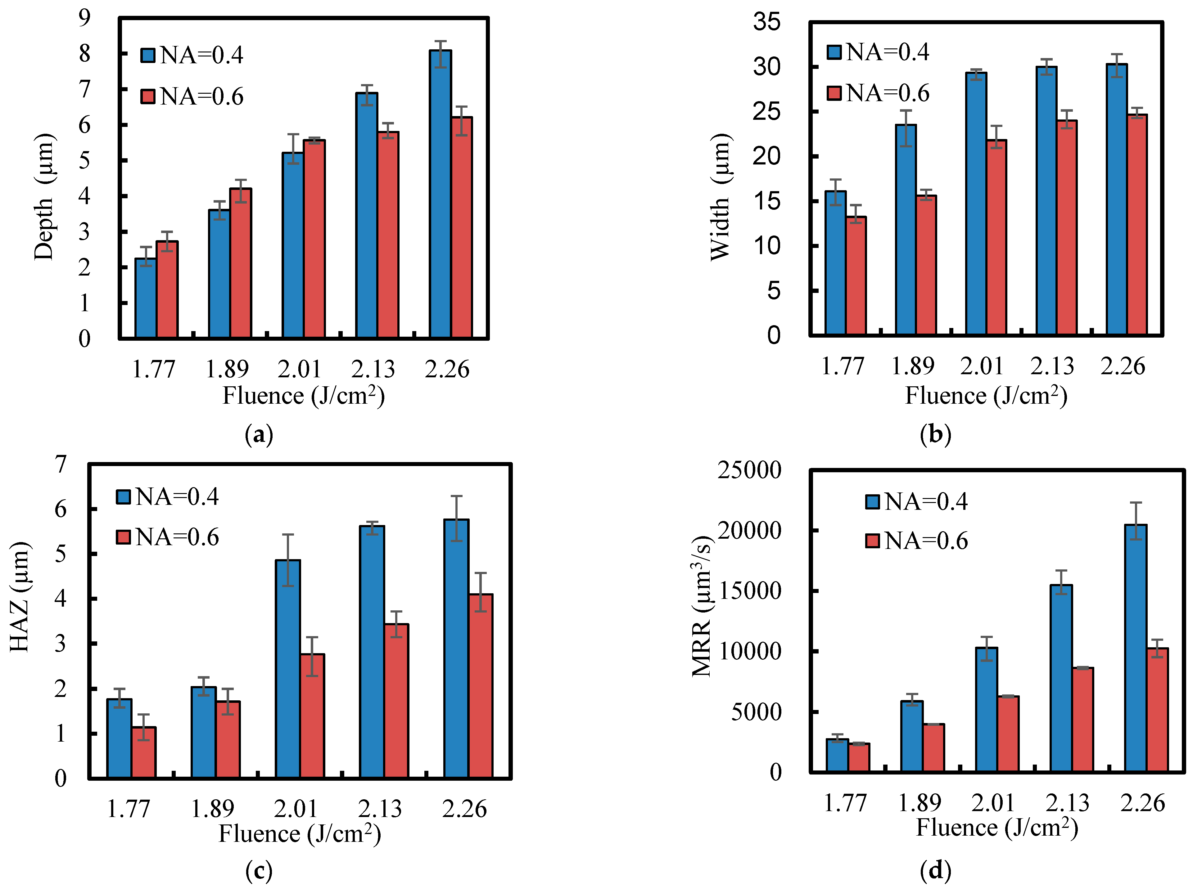
3.2.1. Analysis of Single Factor Experimental Results

Figure 3 shows the fluence distribution of Gaussian beam. The spatial distribution of Gaussian beam shows that the energy is mainly concentrated in the center of the laser spot, so only the energy at the center of the spot is greater than the ablation threshold energy. As the laser fluence increases, the central radius of the spot area with energy greater than the ablation threshold increases. The distribution of laser fluence in the direction of spot radius is [9]:
F r = F m a x e 2 r 2 ω 0 2  
where F m a x . is the peak fluence, r is the radial size, and ω0 is the waist radius.
From Equation (1), it can be seen that in the direction of laser radius, the laser fluence decreases exponentially with the increase in radius. As the peak fluence increases, more energy is injected into the workpiece in the laser propagation direction, and the change in the depth direction of the groove is more significant than the change in the width direction of the groove.
Figure 4 shows the effect of fluence on the size of groove, MRR, HAZ and side wall inclination angle. As shown in Figure 4a, as the fluence increases, the temperature and carrier density in the conduction band increase, thereby increasing light absorption [23]. The more energy is deposited in the material and the groove is wider and deeper. As shown in Figure 4b, the MRR increases with the increase in laser fluence. Due to the high laser fluence allowing more energy to be input into the material at a constant scan speed and pulse repetition rate, the depth and width of the groove increase, resulting in an increase in the cross-sectional area of the groove. It can be seen from Figure 4c that with the increase in laser fluence, the laser cladding layer increases and the HAZ increases. The recoil force is the main reason for the irregular edges of redeposition and recasting humps [24]. As shown in Figure 4d, as the laser fluence increases, material removal increases, the inclination angle of the sidewall increases and the grooves become steeper.
Figure 5 shows the effect of scan speed on the size of groove, MRR, HAZ and side wall inclination angle. With the increase in laser scan speed, the laser energy received by SiC in unit time decreases and the width, depth, side wall inclination angle and HAZ of the groove gradually decrease. The laser energy deposited into the material is directly proportional to the spot overlap rate (PO), and the spot overlap rate and effective pulse number (N0) can be expressed as [7]:
PO = ( 1 S f D   )   100 %
N 0 = 1 1 P O = f D S .
In the formula, D is the diameter of the laser spot on the workpiece, S is the scanning speed and f is the repetition rate.
According to Equations (2) and (3), when the scan speed increases from 50 µm/s to 450 µm/s, the spot overlap rate decreases from 99.86% to 98.77%. As can be seen from Figure 5a,b, with the increase in scan speed, the overlap rate of light spot decreases, and the energy of injected material decreases, so the material removal decreases. It can be seen from Figure 5c,d that with the increase in scan speed, the number of effective pulses decreases and the HAZ decreases. Due to the decrease in groove depth, groove width and groove cross-sectional area, the inclination angle of the material sidewall decreases.
Figure 6 shows the effect of repetition rate on the size of groove, MRR, HAZ and side wall inclination angle. As shown in Figure 6a, the size of the groove increases with the increase in pulse repetition rate. When the repetition rate increases from 200 Hz to 1 kHz, the spot overlap rate increases from 97.95% to 99.59%, resulting in an increase in the laser energy received by the workpiece per unit time.
As shown in Figure 6b, with the increase in repetition rate, the MRR increases. Increasing the repetition rate of laser pulses can provide more energy for the target material of a given area at constant scan speed and laser fluence, thereby increasing the cross-sectional area and achieving a higher MRR. It can be seen from Figure 6c,d that with the increase in repetition rate, the energy of injected material increases and the HAZ and side wall inclination angle increase.
Figure 7 shows the effect of multipass scans on the groove size, MRR, HAZ and side wall inclination angle. Figure 7a,b show that repeated scanning increases the laser energy injected into the groove, increases the material absorption rate induced by multi-pulse laser [23] and melts the amorphous material in the groove under the repeated high temperature caused by multi pulse laser. Therefore, the groove depth and MRR increase with the increase in multipass scanning. Due to the fixed diameter of the spot, the groove width slightly increases with the increase in multipass scanning. It can be seen from Figure 7c that with the increase in multipass scanning, the laser energy is injected repeatedly, the laser energy at the edge of the spot accumulates and the HAZ increases. As shown in Figure 7d, as the number of scans increases, the inclination angle of the sidewall increases and the sidewall of the V-shaped groove become steeper.
Figure 8 shows the influence of numerical aperture on the size of groove, HAZ and MRR. With the increase in the numerical aperture, the focus energy of the processing area increases while the focus energy of the HAZ decreases in the direction of the laser radius. It can be seen from Figure 8a–c that with the increase in numerical aperture, the groove depth increases and the groove width and HAZ decrease. When NA = 0.6, as the fluence increases, due to the width of the groove is smaller, the recast material accumulates and blocks in the groove and the groove depth first increases and then remains unchanged. As shown in Figure 8d, an increase in numerical aperture means a decrease in the size of the laser spot and a decrease in the cross-sectional area of the groove, resulting in a decrease in MRR.

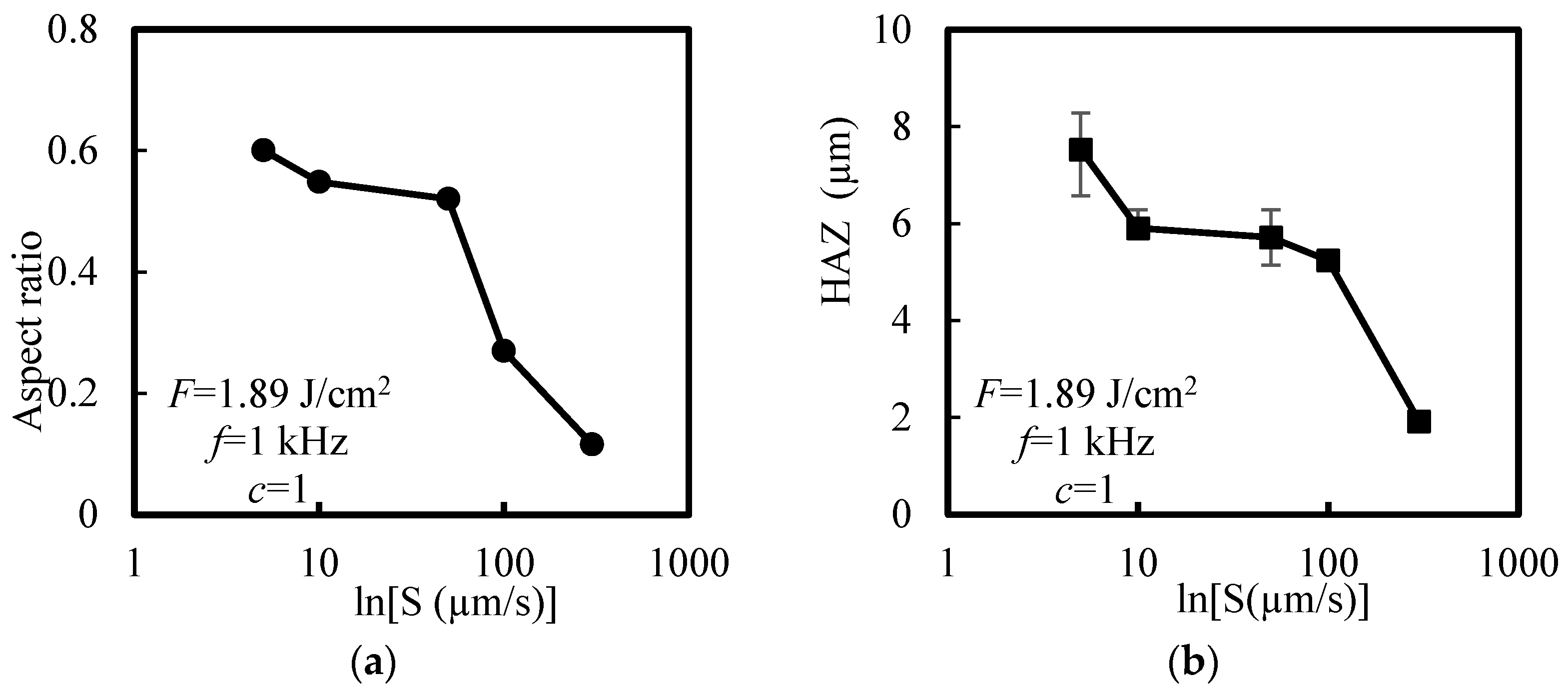
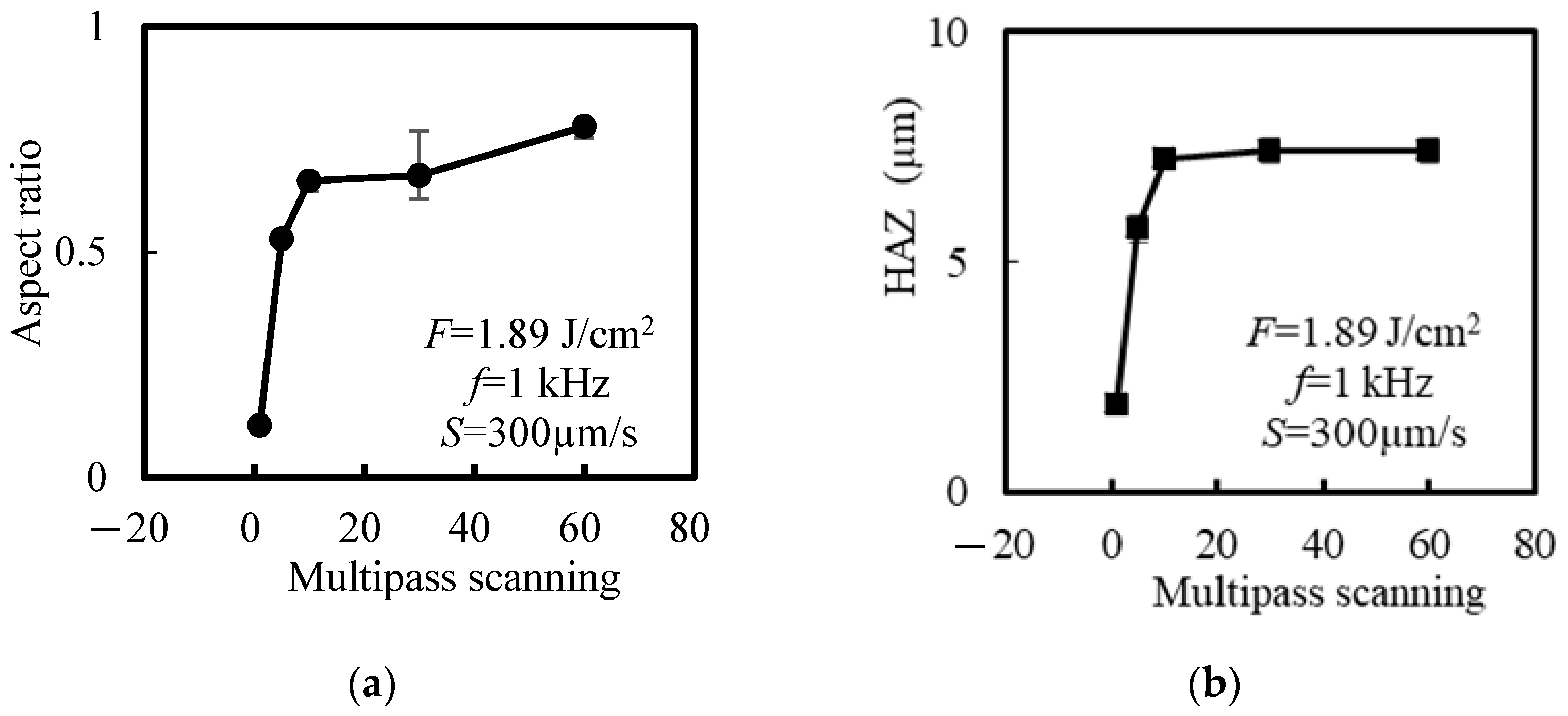
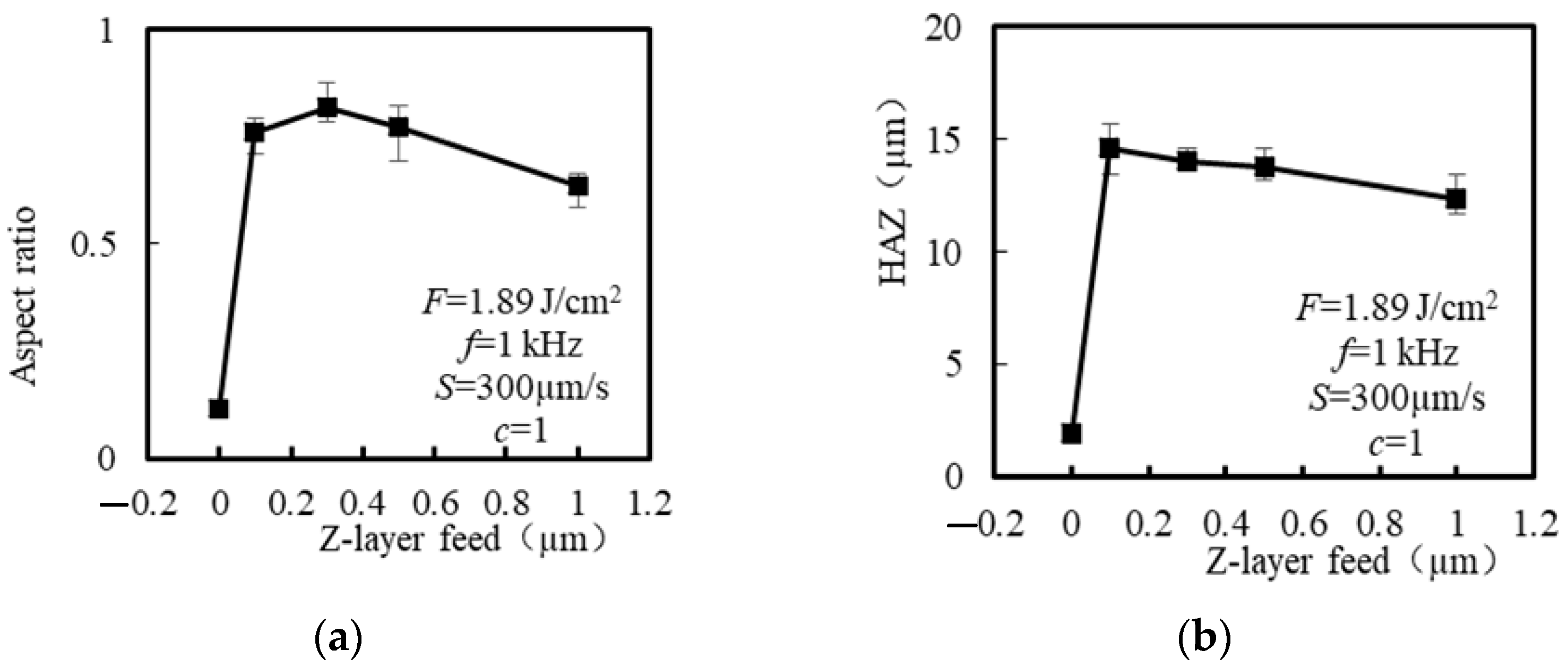
3.2.2. Analysis of the Experimental Results of the Aspect Ratio and the HAZ Width of Grooves

Figure 9 shows the effect of laser fluence on the aspect ratio and the HAZ of the groove. As shown in Figure 9a, the maximum aspect ratio of the groove is 0.15. According to Section 3.2.1, since the laser fluence has a greater impact on the groove depth than the groove width, increasing the fluence can increase the aspect ratio of the groove. It can be seen from Figure 9b that increasing the fluence can increase the HAZ of the groove, and the maximum HAZ is 5.62 µm.
Figure 10 shows the effect of scan speed on the aspect ratio and HAZ of grooves. When the scan speed is 5 µm/s, the maximum aspect ratio is 0.6 and the HAZ is 7.52 µm. Figure 11 shows the effect of scan speed on the ablation morphology. It can be seen from the figure that with the increase in scan speed, ripples appear on the side wall of the groove and in the HAZ. Due to a decrease in scan speed and an increase in spot overlap rate, the injected laser energy increases, resulting in a recast layer at the edge of the groove and a valley-like overlap layer on the side wall of the groove [5,6].
Figure 12 shows the effect of multipass scanning on the aspect ratio and the HAZ of grooves. As shown in Figure 12a, as the number of scans increases, the aspect ratio of the groove increases. When the number of scans is 60, the maximum aspect ratio is 0.79. Figure 12b shows that the HAZ is basically unchanged due to the limitation of the spot diameter when the number of scans is 10, 30 and 60.
Figure 13 shows the effect of multipass scanning on the ablation morphology. When scanning with a single laser beam, due to the Gaussian distribution of the laser beam, the center of the groove is coarse ripple structure, and the edge is fine ripple structure. As the number of multi-pass scans increases, thermal damage caused by thermal accumulation will form at the edge of the laser spot, resulting in an increase in irregular craters on the sidewall of the groove. Figure 14 shows the effect of multipass scanning on the ablation profile. As the number of scans increases, the depth and width of the groove increase.
Figure 15 shows the effect of polarization angle on the aspect ratio and the HAZ of grooves. As shown in Figure 15a, the polarization angle has little effect on the aspect ratio of the groove. Due to the same material removal mechanism, laser polarization mainly affects the direction of the electric field distribution, without affecting the total energy transferred to the workpiece. Therefore, the depth of the groove is mainly affected by variables related to energy, such as laser fluence, scan speed, repetition rate, etc., but is little affected by the polarization of the stimulated light. It can be seen from Figure 15b that the HAZ slightly increases with the increase in polarization angle due to the acceleration of the photoelectric field on the super-hot electron jet.
By using a z-layer feeding layer-by-layer machining method, both sides of the groove will interfere with the laser beam, so excessive feeding layers will limit the removal of the groove. For the same objective and laser parameters, the Rayleigh length is a collimation distance, and the ablation process is carried out on the focal plane. When z = 0, the HAZ is 1.92 µm, and the aspect ratio is 0.12. When the laser is fed downwards, the radiation area of the material increases, resulting in a significant increase in groove width. Although a certain depth was fed, some of the laser was reflected and scattered, so the next processing cannot produce the same depth as the initial processing. The depth of the groove is less than the total feed rate and decreases with the increase in the z-layer feed step.
Figure 16 shows the effect of z-layer feeding on the aspect ratio of groove and the HAZ. It can be seen from the figure that with the increase in feed step, the aspect ratio and the HAZ decrease, and the maximum aspect ratio is 0.82. When the feed step size of z layer decreases, the number of repeated feeds required increases, which can significantly improve the aspect ratio, but at the cost of increasing the HAZ and processing time. Figure 17 shows the effect of z-layer feeding on the ablation morphology. It can be seen from Figure 17a–c that the side wall of the groove presents uneven blocky structure and fine particles, and the HAZ presents an irregular recast layer. It can be seen from Figure 17d–f that when the multipass scanning is 30 and the feed step is 1 µm, the side wall of the groove has an uneven periodic corrugated structure, a small amount of crater structure and a small amount of recast layer in the HAZ. The z-layer feeding method is an improvement on the multipass scanning, but the aspect ratio is greater than that obtained by the same scanning time.

4. Conclusions

This study aims to investigate the significance and analyze the variance of different factors that can influence femtosecond laser processing of single-crystal SiC, through experimental methods. The findings indicate that laser fluence and numerical aperture have a significant impact on the size of groove and the HAZ during femtosecond laser processing of single-crystal SiC. The study findings suggest that repetition rate and multipass scanning have a considerable influence on groove depth, MRR, HAZ and sidewall inclination angle during the femtosecond laser processing of single-crystal SiC. Additionally, they also moderately affect the groove width. The scan speed has a significant effect on the groove depth, groove width, HAZ and side wall inclination angle but has insignificant effect on the MRR. Increasing the laser energy injected into the workpiece, such as increasing the fluence, reducing the scan speed, increasing the repetition rate, increasing the multipass scanning and increasing the numerical aperture, can increase the material removal and HAZ.
The effects of process parameters on the aspect ratio and the HAZ of grooves were experimentally studied. The results show that the aspect ratio and the HAZ can be increased by increasing the multipass scanning, increasing the laser fluence, decreasing the scan speed and decreasing the z-layer feed step. Increasing the laser polarization angle will slightly increase the HAZ width on the surface of single-crystal SiC but has little effect on the size of the groove. With an increase in the number of scans, the aspect ratio of the groove also increases. However, due to the spot diameter limitation, the HAZ remains relatively unchanged when the number of scans is 10, 30 and 60. Furthermore, the aspect ratio obtained through the z-layer feeding method is greater compared to that obtained through the same scanning time.

Author Contributions

Conceptualization, R.Z. and Q.W.; methodology, R.Z. and Q.W.; validation, Q.C. and A.T.; investigation, R.Z. and Q.W.; data curation, R.Z. and Q.W.; writing—original draft preparation, R.Z.; writing—review and editing, Q.W., Q.C., A.T. and W.Z.; visualization, R.Z.; supervision, R.Z.; project administration, Q.C., Q.W. and A.T. All authors have read and agreed to the published version of the manuscript.

Funding

This research was funded by Jinan City School Integration Development Strategy Engineering Project: Intelligent Manufacturing “VR+” Online Education Technology Innovation Research Institute, funder grant number JNSX2021050; Construction of Case Library for the Course of Intelligent Manufacturing Technology Based on VR Technology, funder grant number ALK202108; and the High Quality Curriculum Construction Project of Shandong Jianzhu University Graduate Education, funder grant number YZKC202210.

Institutional Review Board Statement

Not applicable.

Informed Consent Statement

The manuscript is approved by all authors for publication.

Data Availability Statement

The data that support the findings of this study are available from the corresponding author upon reasonable request.

Conflicts of Interest

The authors declare no conflict of interest. The manuscript is approved by all authors for publication, and it is not under consideration for publication elsewhere, in whole or in part.

References

  1. Casady, J.B.; Johnson, R.W. Status of silicon carbide (SiC) as a wide-bandgap semiconductor for high-temperature applications: A review. Solid-State Electron. 1996, 39, 1409–1422. [Google Scholar] [CrossRef]
  2. Chichkov, B.N.; Momma, C.; Nolte, S.; Von Alvensleben, F.; Tünnermann, A. Femtosecond, picosecond and nanosecond laser ablation of solids. Appl. Phys. A Mater. Sci. Process. 1996, 63, 109–115. [Google Scholar] [CrossRef]
  3. Zhang, R.; Huang, C.; Wang, J.; Zhu, H.; Yao, P.; Feng, S. Micromachining of 4H-SiC using femtosecond laser. Ceram. Int. 2018, 44, 17775–17783. [Google Scholar] [CrossRef]
  4. Zhang, R.; Huang, C.; Wang, J.; Feng, S.; Zhu, H. Evolution of micro/nano-structural arrays on crystalline silicon carbide by femtosecond laser ablation. Mater. Sci. Semicond. Process. 2021, 121, 105299. [Google Scholar] [CrossRef]
  5. Rehman, Z.U.; Janulewicz, K.A. Structural transformations in femtosecond laser-processed n-type 4H-SiC. Appl. Surf. Sci. 2016, 385, 1–8. [Google Scholar] [CrossRef]
  6. Mastellone, M.; Bellucci, A.; Girolami, M.; Montereali, R.M.; Orlando, S.; Polini, R.; Trucchi, D.M. Enhanced selective solar absorption of surface nanotextured semi-insulating 6H–SiC. Opt. Mater. 2020, 107, 109967. [Google Scholar] [CrossRef]
  7. Manickam, S.; Wang, J.; Huang, C.Z. Laser-material interaction and grooving performance in ultrafast laser ablation of crystalline germanium under ambient conditions. J. Eng. Manuf. 2013, 227, 1714–1723. [Google Scholar] [CrossRef]
  8. Qi, L.; Nishii, K.; Yasui, M.; Aoki, H.; Namba, Y. Femtosecond laser ablation of sapphire on different crystallographic facet planes by single and multiple laser pulses irradiation. Opt. Lasers Eng. 2010, 48, 1000–1007. [Google Scholar] [CrossRef]
  9. Sudani, N.; Venkatakrishnan, K.; Tan, A.B. Experimental study of the effect of pulsewidth on ablation of silicon substrate using mega hertz repetition rate femtosecond laser. Mater. Manuf. Process. 2011, 26, 661–667. [Google Scholar] [CrossRef]
  10. Gen, N. Research on Femtosecond Laser Processing of Microstructure on Silicon Surface. Master’s Thesis, Tianjin University, Tianjin, China, 2006; pp. 21–29. [Google Scholar]
  11. Li, C.; Shi, X.; Si, J.; Chen, T.; Chen, F.; Liang, S.; Hou, X. Alcohol-assisted photoetching of silicon carbide with a femtosecond laser. Opt. Commun. 2009, 282, 78–80. [Google Scholar] [CrossRef]
  12. Ma, Y.; Shi, H.; Si, J.; Ren, H.; Chen, T.; Chen, F.; Hou, X. High-aspect-ratio grooves fabricated in silicon by a single pass of femtosecond laser pulses. J. Appl. Phys. 2012, 111, 093102. [Google Scholar]
  13. Zheng, Q.; Fan, Z.; Jiang, G.; Pan, A.; Yan, Z.; Lin, Q.; Mei, X. Mechanism and morphology control of underwater femtosecond laser microgrooving of silicon carbide ceramics. Opt. Express 2019, 27, 2–18. [Google Scholar] [CrossRef] [PubMed]
  14. Khuat, V.; Ma, Y.; Si, J.; Chen, T.; Chen, F.; Hou, X. Fabrication of through holes in silicon carbide using femtosecond laser irradiation and acid etching. Appl. Surf. Sci. 2014, 289, 529–532. [Google Scholar] [CrossRef]
  15. Gao, B.; Chen, T.; Khuat, V.; Si, J.; Hou, X. Fabrication of grating structures on silicon carbide by femtosecond laser irradiation and wet etching. Chin. Opt. Lett. 2016, 14, 021407. [Google Scholar] [CrossRef] [Green Version]
  16. Li, Y.; Chen, T.; Pan, A.; Li, C.; Tang, L. Parallel fabrication of high-aspect-ratio all-silicon grooves using femtosecond laser irradiation and wet etching. J. Micromech. Microeng. 2015, 25, 115001. [Google Scholar] [CrossRef]
  17. Zhao, L.L.; Wang, F.; Xie, J.; Zhao, W.W. Fabrication of high-aspect-ratio structural change microregions in silicon carbide by femtosecond Bessel beams. Adv. Mater. Res. 2015, 1102, 143–147. [Google Scholar] [CrossRef]
  18. Xia, B. The Mechanism and Online Observation of High-Quality and High Aspect Ratio Micro Hole Machining Using Femtosecond Laser. Ph.D. Thesis, Beijing University of Technology, Beijing, China, 2016; pp. 69–95. [Google Scholar]
  19. Yang, M. Femtosecond Laser Induced Microstructures and Nanostructures on Silicon Surface. Ph.D. Thesis, Nankai University, Tianjin, China, 2014; pp. 4–6. [Google Scholar]
  20. Qi, Y. Research on the Ablation of Semiconductor and Metal Materials by Femtosecond Laser. Ph.D. Thesis, Jilin University, Jilin, China, 2014; pp. 64–69. [Google Scholar]
  21. Zhang, R.; Huang, C.; Wang, J.; Chu, D.; Liu, D.; Feng, S. Experimental investigation and optimization of femtosecond laser processing parameters of silicon carbide–based on response surface methodology. Ceram. Int. 2022, 48, 14507–14517. [Google Scholar] [CrossRef]
  22. Zhang, R.; Huang, C.; Wang, J.; Zhu, H.; Liu, H. Industrial Lubrication and Tribology. Ind. Lubr. Tribol. 2021, 73, 718–726. [Google Scholar] [CrossRef]
  23. Zhao, Q.Z.; Ciobanu, F.; Malzer, S.; Wang, L.J. Enhancement of optical absorption and photocurrent of 6H-SiC by laser surface nanostructuring. Appl. Phys. Lett. 2007, 91, 121107. [Google Scholar] [CrossRef]
  24. Li, W.B. Research on the Process of Femtosecond Laser Polishing Silicon Carbide Ceramic Materials. Master’s Thesis, Harbin Institute of Technology, Harbin, China, 2011; pp. 16–18. [Google Scholar]
Figure 1. Machined surface morphology of groove shape.
Applsci 13 07533 g001
Figure 2. Laser beam movement mode.
Applsci 13 07533 g002
Figure 3. Fluence distribution of Gaussian beam (F1 > F2).
Applsci 13 07533 g003
Figure 4. Effect of fluence on groove size, MRR, HAZ and side wall inclination angle. (a) Depth and width; (b) MRR; (c) HAZ; (d) side wall inclination angle.
Applsci 13 07533 g004aApplsci 13 07533 g004b
Figure 5. Effect of scan speed on groove size, MRR, HAZ and side wall inclination angle. (a) Depth and width (b) MRR; (c) HAZ; (d) side wall inclination angle.
Applsci 13 07533 g005aApplsci 13 07533 g005b
Figure 6. Effect of repetition rate on groove size, MRR, HAZ and side wall inclination angle. (a) depth and width; (b) MRR; (c) HAZ; (d) side wall inclination angle.
Applsci 13 07533 g006aApplsci 13 07533 g006b
Figure 7. Effect of multipass scans on groove size, MRR, HAZ and side wall inclination angle. (a) depth and width (b) MRR; (c) HAZ; (d) side wall inclination angle.
Applsci 13 07533 g007aApplsci 13 07533 g007b
Figure 8. Effect of numerical aperture on groove size, HAZ and MRR. (a) Depth; (b) width; (c) HAZ; (d) MRR.
Applsci 13 07533 g008
Figure 9. Influence of laser fluence on the aspect ratio and HAZ of grooves. (a) Aspect ratio; (b) HAZ.
Applsci 13 07533 g009
Figure 10. Effect of scan speed on the aspect ratio and HAZ of grooves. (a) Aspect ratio; (b) HAZ.
Applsci 13 07533 g010
Figure 11. Effect of scan speed on ablation morphology. (a) Morphology at S = 5 µm/s; (b) HAZ at S = 5 µm/s; (c) Side wall at S = 5 µm/s; (d) morphology at S = 300 µm/s; (e) HAZ at S = 300 µm/s; (f) side wall at S = 300 µm/s.
Applsci 13 07533 g011
Figure 12. Effect of multipass scanning on the aspect ratio and HAZ of grooves. (a) Aspect ratio; (b) HAZ.
Applsci 13 07533 g012
Figure 13. Effect of multipass scanning on femtosecond laser ablation morphology. (a) Morphology at c = 1; (b) side wall at c = 1; (c) HAZ at c = 1; (d) morphology at c = 60; (e) side wall at c = 60; (f) HAZ at c = 60.
Applsci 13 07533 g013
Figure 14. Effect of multipass scanning on ablation profile. (a) 3D topography at c = 1; (b) profile at c = 1; (c) 3D topography at c = 30; (d) profile at c = 30.
Applsci 13 07533 g014
Figure 15. Effect of polarization angle on the aspect ratio and HAZ of grooves. (a) Aspect ratio; (b) HAZ.
Applsci 13 07533 g015
Figure 16. Effect of z-layer feeding on the aspect ratio and HAZ of grooves. (a) Aspect ratio; (b) HAZ.
Applsci 13 07533 g016
Figure 17. Effect of z-layer feed on ablation morphology. (a) Morphology at Δz = 0.1 µm; (b) side wall at Δz = 0.1 µm; (c) HAZ at Δz = 0.1 µm; (d) morphology at Δz = 1 µm; (e) side wall at Δz = 1 µm; (f) HAZ at Δz = 1 µm.
Applsci 13 07533 g017
Table 1. Single factor experimental scheme.
Experiment 1
ParameterLevel 1Level 2Level 3Level 4Level 5
Fluence (J/cm2)1.771.892.012.132.26
Scan speed (μm/s)50150250350450
Repetition rate (Hz)2004006008001000
Multi-scanning12345
NA0.40.6---
Experiment 2
ParameterLevel 1Level 2Level 3Level 4Level 5
Fluence (J/cm2)1.771.892.012.132.26
Scan speed (μm/s)51050100300
Polarization angle (°)0306090-
Multi-scanning15103060
Feed step size Δz (µm)00.10.30.51
Table 2. Significance analysis of the effect of process parameters on the morphology of grooves.
VariableDepth (µm)Width (µm)MRR (µm3/s)HAZ (µm)Θ (°)
Fluence (J/cm2)***************
Scan speed (µm/s)******-******
Repetition rate (Hz)**************
Multi-scanning**************
NA***************
** moderately significant 0.01 < p ≤ 0.05; *** very significant p ≤ 0.01; - insignificant p > 0.1.
Table 3. Significance analysis of process parameters on processing characteristics.
VariableDepth (µm)Width (µm)Aspect RatioMRR (µm3/s)HAZ (µm)
Fluence (J/cm2)***************
Scan speed (µm/s)***************
Multipass scanning***************
Polarization angle (°)----***
z-layer feed (µm)***************
*** very significant p ≤ 0.01; - insignificant p > 0.1.
Disclaimer/Publisher’s Note: The statements, opinions and data contained in all publications are solely those of the individual author(s) and contributor(s) and not of MDPI and/or the editor(s). MDPI and/or the editor(s) disclaim responsibility for any injury to people or property resulting from any ideas, methods, instructions or products referred to in the content.

