Article

Comparison of Electrochemically Deposited Bi and Sn Catalysts onto Gas Diffusion Electrodes for the Electrochemical CO2 Reduction Reaction to Formate

1
Department of Electrochemical Energy Systems, Research Institute for Precious Metals & Metals Chemistry (fem), Katharinenstrasse 17, 73525 Schwäbisch Gmünd, Germany
2
Institute of Technical Chemistry, University of Stuttgart, Pfaffenwaldring 55, 70569 Stuttgart, Germany
*
Author to whom correspondence should be addressed.
Appl. Sci. 2023, 13(13), 7471; https://doi.org/10.3390/app13137471
Submission received: 4 May 2023 / Revised: 16 June 2023 / Accepted: 21 June 2023 / Published: 24 June 2023
(This article belongs to the Section Chemical and Molecular Sciences)

Abstract

:
In this publication, we report about the selectivity and stability of bismuth (Bi)- and tin (Sn)-based electrocatalysts for the electrochemical CO2 reduction reaction (eCO2RR) for formate production. Bismuth and tin were successfully electrodeposited using the pulse plating technique on top of and inside of the gas diffusion layers (GDLs). The distribution of the catalyst throughout the thickness of the gas diffusion electrodes (GDEs) was investigated by using scanning electron microscopy and computer tomography; it was found that the catalyst morphology determines the performance of the electrode. Inhomogeneous deposits, with their enlarged catalyst surface area, provide more active centres for the eCO2RR, resulting in increased Faraday efficiency (FE) for formate. The initial electrochemical characterisation tests of the bismuth- and tin-loaded GDEs were carried out under laboratory operating conditions at an industrially relevant current density of 200 mA·cm−2; complete Sn dissolution with a subsequent deformation of the GDL was observed. In contrast to these results, no leaching of the electrodeposited Bi catalyst was observed. An FE of 94.2% towards formate was achieved on these electrodes. Electrodes based on an electrodeposited Bi catalyst on an in-house prepared GDL are stable after 23 h time-on-stream at 200 mA·cm−2 and have very good selectivity for formate.

1. Introduction

To achieve the global climate targets, the investigation of new technologies for a decarbonized energy production and storage method as well as defossilised chemical production method is inevitable. With the use of renewable electricity generated from solar or wind sources, CO2 can be used as raw material for the electrochemical CO2 reduction reaction (eCO2RR) [1,2,3,4,5]. The electrochemical conversion of CO2 into a diverse spectrum of chemicals is a potential technology to change the role of CO2 from harmful waste to a valuable resource. Depending on the electrocatalyst, value-added products such as CO, formate/formic acid, alcohols, and other hydrocarbons can be produced from CO2 by the eCO2RR reaction [6,7,8,9,10].
Besides CO, formate/formic acid is an easily accessible product that can be used in various industrial applications and in downstream processes in the chemical industry [4,11,12]. The most common catalysts for the eCO2RR reaction to formate/formic acid are based on tin (Sn) and bismuth (Bi). Both of these elements exhibit high selectivity towards formate/formic acid and high overpotentials towards the hydrogen evolution reaction [4,13,14,15,16,17,18,19]. Additionally, these catalysts are of interest because of their non-toxic properties and low cost [20].
To achieve industrially relevant current densities of 200 mA·cm−2 and greater, the use of gas diffusion electrodes (GDEs) is necessary [21,22]. State-of-the-art GDEs are fabricated by depositing a catalyst layer on a gas diffusion layer (GDL) [23,24]. This is typically performed by spray coating an ink [25,26,27,28] consisting of the catalyst, a binder, and a solvent onto the gas diffusion layer. Typically, to obtain the catalyst, the active phase (electrocatalyst) is deposited on a conducting support consisting of mainly carbon materials by a precipitation process [29].
Electrodeposition is a cost-effective and uncomplicated method that offers the possibility to selectively place catalyst particles at active positions of the triple-phase boundary [30]. Through a suitable choice of substrate, process, and electrolyte parameters, the nucleation rate and morphology of the precipitates can be influenced. As shown in the literature, defects, grain sizes, and orientation of the catalyst material that can be influenced in this way have a decisive influence on the selectivity and activity of the catalyst in the electrochemical CO2 reduction [14,15,16,17,18,31,32,33,34,35,36,37]. Compared with the other techniques available, electrodeposition is the most straightforward method to fabricate large electrodes for real industrial electrolysers.
Aside from galvanostatic deposition, pulse current deposition (pulse plating, PP) is one of the most commonly techniques used in electrodeposition. It is known that the morphology, microstructure, hardness, ductility, porosity, and surface roughness of electrodeposits are impacted by the process parameters [20]. PP also yields a finer, homogeneous surface appearance because it is possible to achieve higher instantaneous current densities during electrodeposition.
In the literature, various metals (Sn, Bi, Pb, Hg, In) [13,21,22,23,24,25,26,27,29,30,31,32,33,38,39,40,41] have been investigated for the production of formate from CO2 by electrolysis according to the following reaction:
CO2 + H2O + 2e ⇌ HCOO + OH E0 = −0.72 V
In most of the published papers, the catalyst precursors were deposited using the precipitation method, or the catalyst was used in the form of an ink. Some authors used electrodeposited catalysts on planar electrode substrates [15,42,43,44,45,46,47,48,49]. Only a few papers used GDEs/GDLs as the substrate for electrochemical deposition of Bi or Sn [50,51,52]. Usually, the electrodes have been investigated at low current densities [15,42,43,44,45,46,47,48] and short reaction times [15,43,45,47,49,52,53,54]. To clearly show the advantages of the electrochemical deposition, some of the results for Bi and Sn catalysts produced by different methods are compared in Table S1. There has been no study where the electrodeposited catalyst on GDE has been tested for long-term stability at the industrially relevant high current density of 200 mA·cm−2.
In this work, Sn and Bi electrocatalysts were electrodeposited from commercial electrolytes using a pulse plating method on in-house fabricated and commercial carbon-based GDLs. The electrodes prepared in this way were investigated by using scanning electron microscopy and computer tomography before and after electrolysis. Different structures and morphologies of both electrocatalysts were electrodeposited on the surface and inside of the GDLs. The electrodes were electrochemically characterised at the high current density of 200 mA·cm−2 and the Faraday efficiency (FE) for formate was determined. The long-term stability (24 h) of the most promising electrodes was tested at industrially relevant current densities. The influence of the different coatings on the performance of the gas diffusion electrode concerning activity, selectivity, and stability in eCO2RR was analysed. The catalytic performance (activity, selectivity, lifetime) of the electrodes was compared with GDEs that were produced via a precipitation method.
To achieve the high catalytic activity, selectivity, and long-term stability of the system, it is not only the catalyst selection, electrode materials and deposition techniques that are important. The choice of electrolyte [36,55,56,57,58], gas diffusion electrode design [22,23,29,34,35,36,37,59,60,61,62,63,64,65], and reactor design [4,66,67,68,69,70,71,72,73,74] can also influenced the CO2RR reaction. The used cell design for the electrochemical characterisation of the prepared electrodes has been described in previous work [29,36].

2. Materials and Methods

Chemicals: For the gas diffusion layers, 29 BC (SGL CARBON GmbH) (5% Polytetrafluoroethylene, areal weight 90 g·m−2, thickness: ca. 235 µm, el. resistance < 12 mΩ·cm−2 [75]) and in-house (IH) fabricated gas diffusion layers were used; the latter items were prepared by mixing a carbon material (Acetylene Black, AB, Alfa Aesar, >99.9%) with polytetrafluoroethylene (PTFE, Dyneon, TF 92070Z, d ¯ p = 450 µm). For electrodeposition, commercial electrolytes supplied by Schloetter were used (Sn: Slototin MT 1110, conductivity 393 mS/cm; Bi: Slotoson MB 1880, pH 1, conductivity 314 mS/cm). The temperatures that were used were room temperature for Slototin MT 1110 and 45 °C for Slotoson MB 1880. For the anode, a Sn or Bi plate (Schloetter, 30 cm2) was used. Potassium chloride (Carl Roth GmbH & Co KG, ≥99.5%), potassium bicarbonate (Carl Roth GmbH & Co KG, ≥99.9%), and potassium hydroxide (Carl Roth GmbH & Co KG, ≥85.0%) were used as conductive salts in the electrolyte for the electrochemical characterisation.
GDL preparation: The in-house fabricated GDLs were prepared using homogeneous mixing AB with PTFE at a ratio of 65:35 (30% PTFE) followed by dry-pressing at up to 7.29 kN·cm−2 for 4 min and a thermal treatment at 340 °C for 10 min in a nitrogen atmosphere [29]. In contrast to the thinner (235 µm) commercial GDL (Sigracet 29 BC carbon paper) used, for better stability, the in-house fabricated GDLs were thicker (thickness: ca. 900 µm). The two GDLs are schematically shown in Figure S1a,b.
Preparation of GDEs with precipitated electrocatalyst: GDEs with highly dispersed tin- or bismuth-based catalyst were used as the benchmarks for the GDEs with electrodeposited catalysts. First, the catalyst precursors were deposited using a pH-controlled precipitation method on acetylene black. Subsequently, the acetylene black with a deposited catalyst and the PTFE were mixed at a ratio of 65:35 followed by dry-pressing and thermal treating steps. The preparation method is described in detail in our previous work [34].
Preparation of GDEs with electrodeposited electrocatalyst (Scheme in Figure S1c): The electrochemical deposition experiments were conducted using a model SP-150 potentiostat/galvanostat (BioLogic) and were controlled using EC-Lab Software (BioLogic). The GDLs were coated using Sn electrolyte at room temperature (RT) and Bi electrolyte at 45 °C. In the PP experiments, square-wave pulses with cathode pulse current densities (jp) of 5, 10, and 15 A·dm−2 and a pulse time (ton) and relaxation time (toff) of 1:1 s or 0.005:0.05 s (ton/toff), respectively, were used. The used current densities were recommended from the electrolyte producer, and the pulse and relaxation times were based on previous experience. The average current density jav was calculated according to the following equation:
jav = jp·ton/(ton + toff) = jp·ton·f = jp θ
The duty cycle θ (θ = ton/(ton + toff), %) and pulse frequency f (f = 1/(ton + toff), Hz) for the used on-/off-times were θ = 50%, f = 0.5 Hz and θ = 9%, f = 18.18 Hz, respectively. These values were chosen according to previous experience and preliminary tests. The electrodeposited amounts of the different catalysts were kept constant by adjusting the deposition times. The reason for doing so is the nature of the GDL. For depositing inside of the GDL, the Bi electrolyte has to easily penetrate into the inside of the GDL. Both investigated GDLs were thick, and PTFE was part of their structure. The hydrophobic properties of PTFE are useful for the eCO2RR reaction but complicate the penetration of an electrolyte into the inside of the GDL and complicate metal deposition. To enhance this process, the GDLs were pre-treated for 2 min in an ultrasonic bath of Sonorex (Bandelin electronics).
The used PP parameters are systemised in Table 1.
GDE characterisations: The surface morphology and chemical composition of the electrodeposits were determined using a high-resolution scanning electron microscope (SEM, Gemini SEM 300, Zeiss) with energy dispersive X-ray spectroscopy (EDX) operated at 15 kV. Computer tomography (CT) cross-sections of the GDEs were performed using a Phoenix VtomexL 450 system (GE Sensing & Inspection Technologies). The phase analysis was performed by using X-ray diffraction in the Bragg–Brentano geometry using a D8 discover Da Vinci diffractometer (Bruker AXS GmbH, Karlsruhe, Germany) equipped with a 1D Lynxeye-XET detector using copper radiation. A variable divergence slit with an opening of 10 mm was used to keep the radiated area of the sample constant during the measurement. The phase analysis was performed by comparing the measured reflections to the ICDD-PDF2 database (International Centre for Diffraction Data). The roughness of the electrodes was investigated using the Nanofocus µsurf custom, (NanoFocus AG, Germany). The evaluation of the data was carried out using the software “Digital Surf MountainsMap® 7.2”.
Electrochemical characterisation: The electrochemical characterisation of the prepared electrodes was performed in a custom-made semi-batch cell constructed from poly(methyl methacrylate) (PMMA). The used cell design was described in a previous work [29]. For the reaction condition, the conditions optimized by Löwe et al. were used as a starting point [36]. For experiments with reaction times (time on stream, TOS) > 1 h, the cell was modified for a continuous exchange of the electrolyte. The electrodes were separated by a cation exchange membrane (Nafion® 117, DuPont). The experiments were conducted using a Gamry Inferface 1010E potentiostat.
For GDEs coated with Sn, 1 M of KHCO3 with a pH value of 10 was used as the electrolyte. Hg/HgO (1 mol/L KOH) served as the reference electrode. A platinum wire was used as the counter electrode. The electrolyte was heated and monitored by an external heat exchanger. On the gas side, a nickel mesh was used as a current collector. To protect the GDE from mechanical destruction by the nickel mesh, a GDL (SGL, Sigracet GDL 35AA) was placed between the mesh and the GDE. For Bi-based catalysts, to avoid the formation of carbonate and bicarbonate in the GDL, 1 M of KCl (pH 10) was used as a catholyte. The other materials and parameters remained the same. For the electrochemical characterisation, the geometrical area of the GDE was limited to 1 cm2 by a PTFE mask. The characterisation was carried out at 50 °C and a CO2 flow rate of 5.57 mL·min−1. These conditions have been shown to be the optimum scenario in a similar system in a previous work [29]. The FE was calculated according to Equation (3) [36]:
F E = n t I z F
where n is the amount of substance (mol), t is the time (s), I is the current (A), z is the number of transferred electrons, and F is the Faraday constant (C·mol−1).
All FE values presented in the manuscript are the average values from 3 different electrodes prepared in the same way.
To characterise the GDE, the current was increased in 60 s from 0 mA·cm−2 to −200 mA·cm−2 as preconditioning. This was followed by a galvanostatic hold for 1 h at −200 mA·cm−2. Long-term experiments over 24 h were performed at a current density of −200 mA·cm−2 and −50 mA·cm−2. The electrolyte was continuously exchanged at a flow rate of 1 mL·min−1. The gaseous products (H2, CO) were analysed using a thermal mass flow meter and online GC (Agilent 7890A). To quantify the formate concentration, a high-performance liquid chromatography (HPLC, Agilent Technology, 1260 Infinity, column: NUCLEOGEL Sugar 810 H) analysis was performed.

3. Results and Discussion

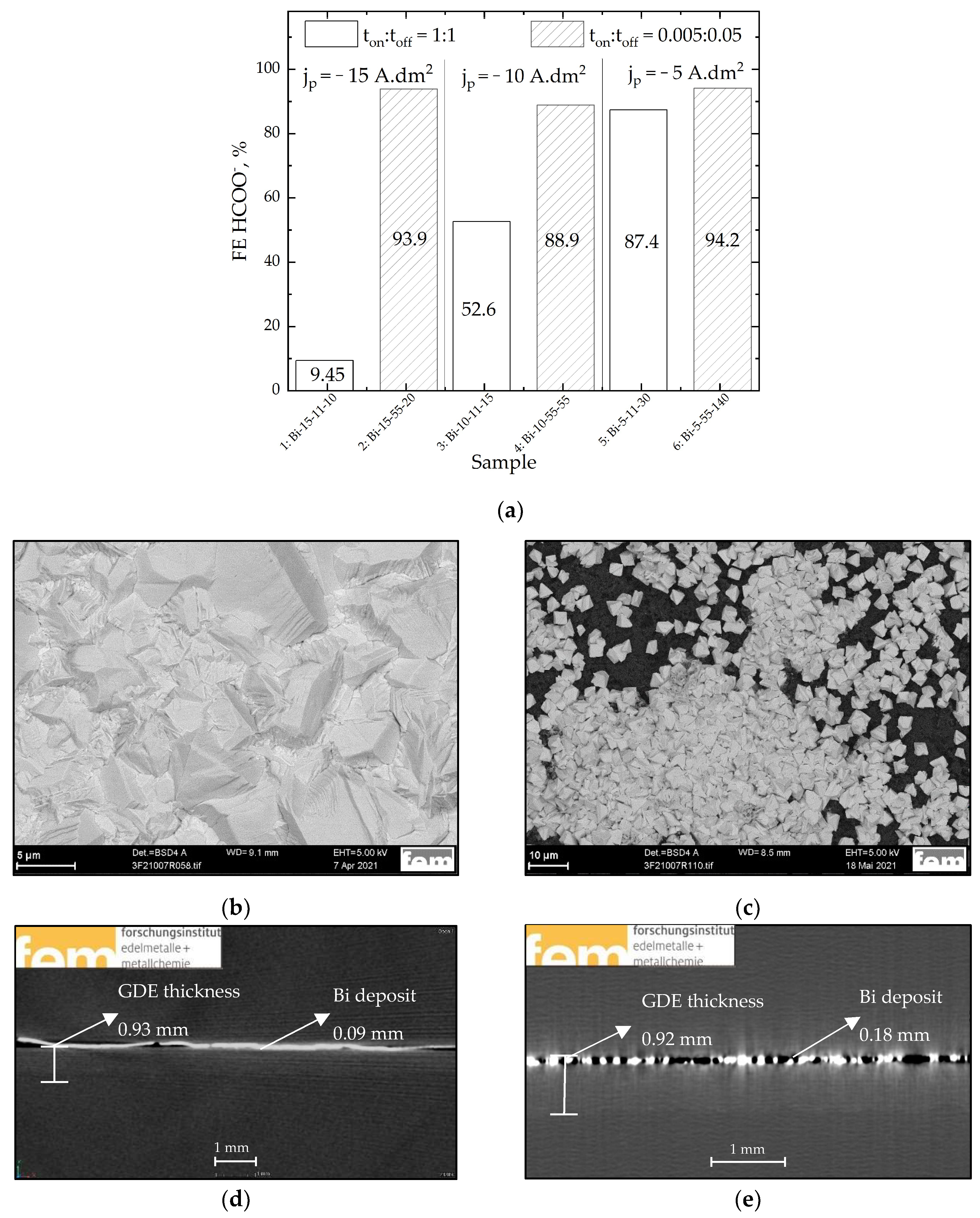
3.1. Bi PP Electrodes Based on In-House GDLs

The performance of the Bi-IH-PP-GDLs for formate production highly depends on the used PP parameters, such as the cathodic pulse current density jp, pulse time ton, and relaxation time toff. (Figure 1a). The PP parameters had an effect on the surface morphology of the deposited Bi, which determines the FE for the formate production. Decreasing jp with a ton:toff of 1:1 led to an increase in the electrode performance from approx. 10% to approx. 90% (white bars in Figure 1a). The deposition time was calculated such that coatings of an equal thickness of 5 µm were deposited. At jp = −15 A·dm−2 and ton:toff = 1s:1s, a compact Bi deposit with crystallites of over 5 µm, which were separated from each other through a few grain boundaries, were electrodeposited on the GDL (Figure 1b). The CT cross-section image shows that the Bi deposit is only located on the top of the GDL (Figure 1d). With the decrease in PP current density, the size of the crystallites decreases (Figure S2a). Small current densities (jp = −5 A·dm−2) lead to the growth of more nuclei on the GDL. The resulting Bi deposit is coarse-grained with crystallites of up to 2 µm (Figure S2b), and it is rich in different defects. This enhances the CO2 diffusion through the catalyst layer. As a result, the FE for formate reaches its maximum value (Figure 2a, white bars, 5 A·dm−2). The potentials of the electrodes are shown in Table S2.
The effect of a short deposition time ton in combination with longer pause time toff on the morphology and electrode performance, respectively, is especially visible at high current densities. The Bi deposit at ton:toff = 1 s:1 s is compact, only being located on the top of the GDL (Figure 1b,d) and having only reached a 10% FE for formate (Figure 1a white bar, jp = −15 A·dm−2). On the surface of Bi-IH-PP deposited at the same jp but with ton:toff = 0.005 s:0.05 s, an increased number of single Bi crystallites and their aggregates randomly grew. This inhomogeneous structure, which is rich in sharp edges, grain boundaries, and other defects, provides an enlarged active surface area. Moreover, the CT cross-section image of the same GDE shows that at ton:toff = 0.005 s:0.05 s, the growth of inhomogeneous insular structures occur not only on the top of the GDE electrode, but also inside of the GDE up to a 170 µm depth (Figure 1e). During CO2 electrolysis, the wetted area as well as the reaction zone moves towards the gas side of the GDL used [76,77]. According to this information, to achieve better electrode performance, the catalyst grains or particles should be evenly distributed not only on the top of the GDL but also inside of the GDL. Due to the reduction of mass transport limitations of CO2 and liquid products, such a catalyst distribution can improve the FE to 90% (Figure 1a, hatched bar, jp = −15 A·dm−2). At this ton:toff, Bi was also deposited inside of the GDLs independent of the used current density (Figure S2c).
The catalyst roughness also influences the FE of the GDEs. A homogeneous Bi catalyst (Bi-15-11-10) with area roughness parameters (Sa) of 1.55 µm has a low FE for formate (10%). Bi deposits with inhomogeneous insular structures (Bi-5-55-140, Figure S1c) with an almost fourfold increase in the Sa of 5.57 µm (Figure S3) reached a greater than 90% FE for formate (Figure 1a).
After CO2 electrolysis, the Bi deposit remains on the top and also inside of the GDL (Figure 2a); however it remains with a structure that has changed (Figure 2b). The Bi crystallites are converted independent of the electrolysis parameters into sharp plates (scales) with enormous surface area (Figure 2b). The EDX spectra show a high amount of oxygen (Figure S4). We suppose that the Bi catalyst was oxidized during the CO2 reduction reaction; this did not change the FE of the electrode, because it is well-known from the literature that Bi-based catalysts are active in oxide and reduced metal forms [50,77,78].
During PP deposition with short deposition time and longer pauses (ton:toff = 0.005 s:0.05 s), thin channels were formed inside of the Bi deposit (Figure 2c). Thus, an increase in the active surface area was achieved. The electrolyte wets and CO2 diffuses are facilitated through the channels inside of the Bi electrocatalyst, and the aimed synergetic effect between catalyst and GDL properties is achieved. As a result, the FE for formate for Bi-IH-PP GDE reaches 93% (Figure 2a).
The Bi-IH-PP GDEs that showed the best results during the shorter eCO2RR (Figure 1a) were tested for the long-term CO2 electrolysis. It is supposed that the most possible reason for this very good performance of the PP electrode is the uneven distribution of the Bi catalyst (see Figure 1c,e) on top of and also inside of the GDL. The FE of formate for all tested Bi-IH-PP electrodes (long-term tests) was greater than 80%, and in some cases, it reached 94%. It was found that the FE was dependent on the GDL that was used. The reproducibility in one GDL batch was 95–100%. However, there were observed distinctions between different batches. Freshly produced GDLs after Bi deposition reached an FE of greater than 94% (Figure 1a). Older batches showed a lower FE because the deposited Bi amount was lower. Egetenmeyer et al. [79] showed that the laser surface etching of GDL before the electrodeposition of Pt enhanced the electrochemical deposition. Most likely, the in-house prepared substrates achieved different aging stages because of time, which only affects the electrochemical deposition. The carried out electrochemical measurements (CV, galvanostatic experiments) of the blank GDL did not show any changes; therefore, in Figure 3, the electrode with the best performance is not shown. The benchmark electrode Bi-IH-P with the fine catalyst distribution is still better (Figure 3) than the Bi-IH-PP electrodes. The electron balance for electrodes with an electrodeposited catalyst is sometimes not closed. In the used setup, the produced hydrogen typically diffuses through the porous GDL towards the gas side of the electrode; it is there that hydrogen, other gaseous products, and non-converted CO2 are detected. Due to the Bi that was deposited on top of the GDE, some H2 was released into the electrolyte on the cathode side, which could be observed as gas bubbles in the electrolyte. A detection of gases at the electrolyte side of the GDL was not possible in the setup used. As a result, the missing FE can be dedicated to H2. A small increase in the HER at TOS > 15 h was observed. After a reaction time of 23 h at these high current densities (200 mA·cm−2), the FE for formate was still 76.4%. The loss on selectivity and the small increase in the HER are not related to a degradation of the Bi catalyst. It is supposed that the growth of sharp plates of oxidized Bi and the restructuring of the last Bi atomic layer mechanically deformed the GDL structure. The optimized relation between the distribution of electrodeposited Bi and the GDL stability must be thoroughly investigated. Through this analysis, it should be possible to fabricate functioning GDEs over a long period of time, which is required for an industrial application of these electrodes. The potentials of the electrodes are shown in Figure S5.

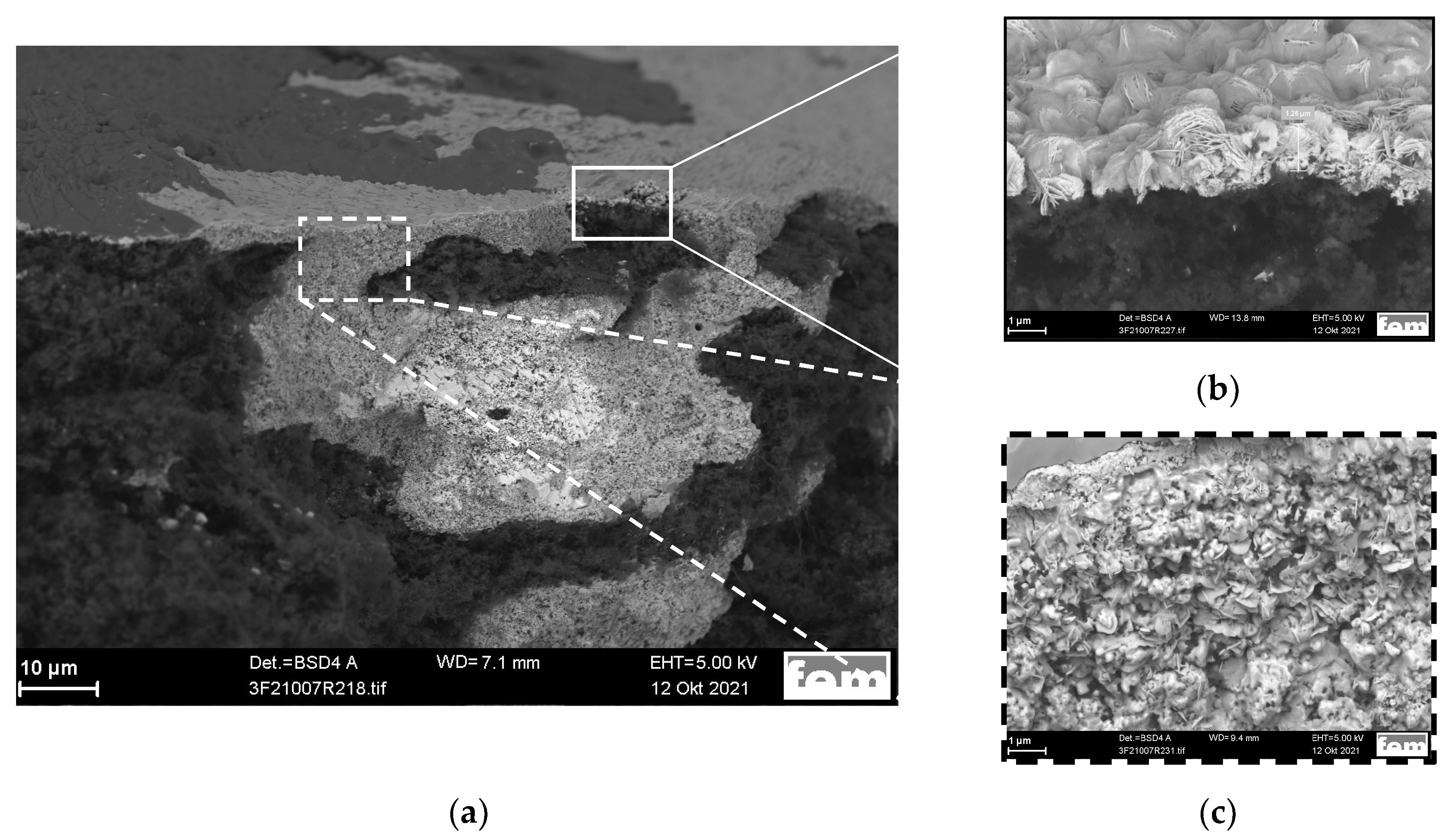
3.2. Bi PP Electrodes Based on 29 BC GDLs

In order to prove if a commercial GDL provides similarly good electrodes when using a PP method to deposit Bi, a 29 BC gas diffusion layer from SGL Carbon was chosen. The BC GDL was thinner (230 µm) and had a structure and composition that was different than the IH GDL. Using SEM images, it was possible to distinguish the different layers of the BC GDL. Using CT imaging, the well-ordered pore structure of the different layers can be seen [30]. After Bi PP depositon, coarse-grained Bi deposits were placed not only on top of the BC but also inside of the microporous layer (Figure 4a). In the middle of the GDL BC, Bi was homogeneously deposited, preserving the well-ordered pore structure (Figure 4b). Bi was deposited into the whole GDL layer down to the backside of it at 190 µm.
In agreement with the investigations on the IH GDL with Bi, no Bi dissolution on the top or inside of the GDL was observed (Figure 4c). The FE reached for formate for 1 h in a Bi-BC-PP electrode was 80%, which is at least 10% lower compared with the Bi-IH-PP and Bi-IH-P GDEs (Figure S6). Until now, it was not possible to achieve a higher FE for formate.
After 24 h of operation at 50 mA·cm−2, only the Bi crystallites transformed into sharp plates (scales) with a higher surface area (inset of Figure 4c). This is in accordance with our results for Bi-IH-PP GDE (see Figure 1b). XRD measurements revealed that the main phase after 24 h of CO2 electrolysis was metallic Bi with a preferred <012> orientation normal to the sample surface. Regarding the intermediate phase, bismutite carbonate (Bi2(CO3)O2) was found. Some reflections with low intensity indicated the presence of potassium bismuth oxide (KBi12O18) in traces (Figure S7). According to the Pourbaix diagram of Bi, under reaction conditions (−1.43 V vs. SHE, pH > 10), the thermodynamically stable Bi species is elementary Bi [80]. The selectivity of the tested Bi-PP-BC electrode did not change with time. The reason for this could be that there is no difference in the reactivity of the metallic Bi phase and Bi oxides in the eCO2RR reaction towards formate [42]. After eCO2RR, the texture of the GDL remained unchanged. This is at odds with our previous research for the Sn catalyst, where the GDL texture was completely destroyed after 1 h of electrolysis [30]. The observed black spots (blemishes) in Figure 4d are only mechanical deformations that are caused by the electrolysis process.
The Bi-BC-PP GDE were also tested for their long-term stability at a higher current density of 200 mA·cm−2. However, the mechanical stability of the GDE based on the commercial GDL was not good enough, and after 10 h, the Bi-BC-PP GDE was mechanically destroyed.
Due to a different structure and composition, the in-house fabricated GDLs are more suitable as substrates for catalysts constructed via electrodeposition compared with the chosen commercial GDLs. With the further optimisation of the structure and composition of GDLs, an optimized electrodeposition of catalysts, and a good understanding of the processes during electrolysis, the long-term stable operation of Bi-GDEs fabricated by the pulse plating technique should be achieved.

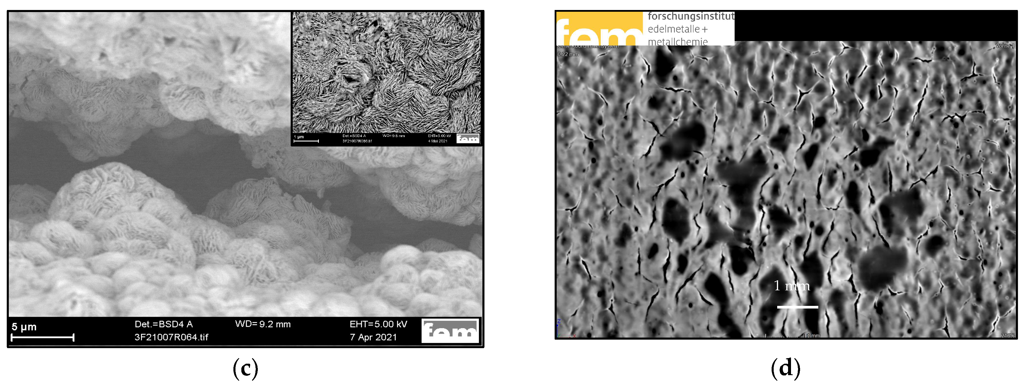
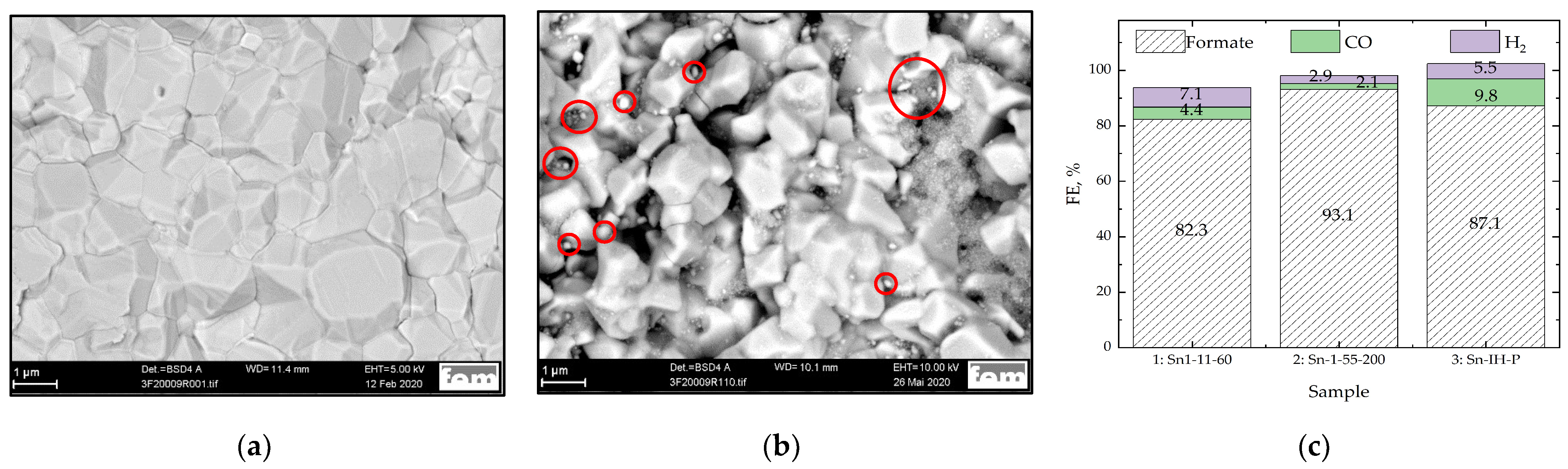
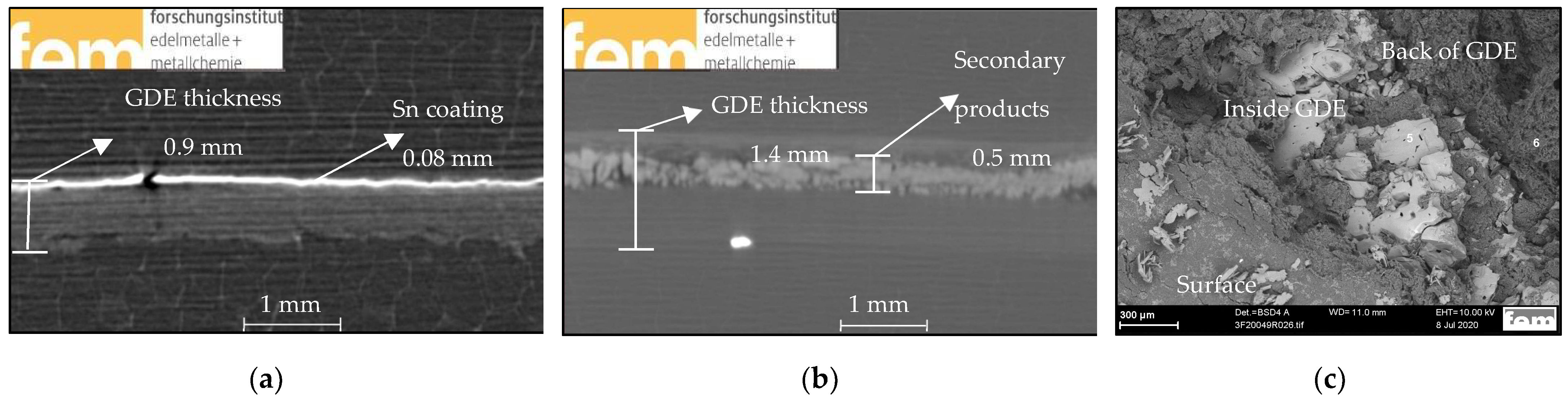
3.3. Sn PP Electrodes Based on In-House GDLs

In our previous work [30], Sn electrodeposition was demonstrated on the top of and inside of the commercial GDL 29 BC. The highest FE for formate that was attained with such GDEs was 85%. In this work, in order to increase the Faraday efficiency for formate as well as the electrode stability for the Sn electrodeposition, the optimized in-house fabricated electrode [37] was used.
Coarse-grained Sn coatings with intergrown crystallites ranging from 0.5 µm to 2 µm were deposited on the top of IH fabricated GDL by PP at jp = −1 A·dm−2 and ton:toff = 1 s:1 s (Figure 5a). At a shorter ton:toff time, single coarse-grained crystallites (1 µm) with sharp edges grew on the GDL surface (Figure 5b). The crystallites were separated from each other through hollows or were grouped into islands. Additionally, unevenly distributed small crystallites with a size of about 0.1 µm were deposited on top of them; some of them are marked with red circles in Figure 5b. It is supposed that such an inhomogeneous surface morphology of the electrodeposited catalyst additionally enlarges the active surface area and will lead to an increased FE of the GDE.
The Sn-IH-PP GDEs were thoroughly investigated in the CO2 electrolysis. As a benchmark, state-of-the-art Sn-IH-P GDEs were used [36,37]. In accordance with the Bi-IH-PP GDEs, it was found that the surface morphology of the electrodeposited Sn coating has an influence on the FE for formate and on the product distribution (Figure 5c). The more compact deposit (Figure 5a), where CO2 mainly penetrated through the grain boundaries and other deposit defects, showed a lower selectivity for formate (FE: 82.3%) than the inhomogeneous deposit (FE: 93.1%) (Figure 5b), where CO2 additionally penetrated through the enlarged catalyst surface (an increased number of sharp edges) and free spaces between the crystallite islands. On the GDL with the pulse plated electrocatalyst with shorter ton:toff time, the FE for formate (93.1%) was even better than that of the Sn-IH-P electrodes (87.1%, Figure 5c, last column). The Sn content of both electrodes (Figure 5c) was comparable (2.6 wt.% Sn on GDEs with precipitated catalyst, 3.7 wt.% Sn on GDEs with electrodeposited catalyst). These electrodes feature a low selectivity for the side products of CO (12%) and H2 (1%), as shown in our previous publication [30]. The potentials of the electrodes are shown in Table S3.
The long-term electrolysis for Sn-IH-PP GDE was carried out at 50 mA·cm−2 because when applying a current density of 200 mA·cm−2, the HER increases after two hours, wherein no stable reaction would be possible after this time. In the beginning of the electrolysis, the FE was at about 97% and was quite stable for 4 h (Figure 6). Then, the selectivity for formate decreased to approximately 90% and was almost stable for another 6 h. The FE for hydrogen evolution reaction at this time was under 2%. After 11 h, the FE for formate decreased in a step-by-step manner. Simultaneously, the HER as a competing reaction became more favoured. This could indicate the leaching of the active catalyst. Furthermore, leaching of a SnOX catalyst prepared by the precipitation method has been reported [34,67]. After 18 h, the main reaction was that the HER and experiment was interrupted.
The same Sn-IH-PP GDE was investigated using CT imaging before and after the long-term electrolysis. The Sn catalyst was only deposited on the surface of the IH-GDL (Figure 7a). After 19 h of CO2 electrolysis at 50 mA·cm−2, the Sn catalyst layer on top of the sample was completely dissolved, large agglomerates were found inside of the GDL, and the GDL thickness increased from 0.9 mm to 1.4 mm (Figure 7b). In the SEM image (Figure 5c), the dark grey areas represent the GDL (Spectra 6, Figure S8a). EDX measurements in some lighter areas on the surface and inside of the GDL (Spectra 5, Figure S8b) revealed the presence of large amounts of K and O. During the long-term electrolysis, secondary products such as carbonates or bicarbonates were formed in a non-Faradaic side reaction at high pH values in the pore systems of the used electrodes. These carbonate salts precipitated inside the GDL and increased its thickness through the process of swelling. Bienen et al. [34] also observed SnO2 leaching from the same in-house fabricated GDL, where the Sn catalyst was not electrochemically deposited but instead had Sn particles finely deposited on the carbon black via a homogeneous precipitation method with urea. According to the Pourbaix diagram of Sn [80], metallic Sn is the thermodynamically stable phase at these potentials at a pH value of at least 10. It must be mentioned that due to the generated OH- ions during the ongoing reactions of eCO2RR and HER, the pH value inside the GDL can significantly exceed the value of 10 [66]. It seems that at such high pH values, and due to the negative potential, the metallic Sn is not stable. Sn dissolves, and over time, less catalyst is available in the deposited layer of the Sn electrocatalyst. Finally, no catalyst remains on the surface (see Figure 7b,c).
To summarise, these results indicate that Sn is not stable as a catalyst for eCO2RR at high current densities. Locally high pH values undoubtedly cause the dissolution of Sn. This can be unambiguously concluded to be due to the complete dissolution of the electrodeposited Sn layer at these conditions.

4. Conclusions

Sn and Bi catalysts were successfully electrodeposited using the pulse plating method on top of and inside of the commercial and in-house fabricated GDLs.
The electrodes were tested in an electrolysis cell at industrially relevant current densities up to 200 mA·cm−2.
It was found that the catalyst morphology determines the performance of the electrode. Inhomogeneous deposits provide more active centres for the CO2 reduction reaction, resulting in an increased FE for formate.
Upon CO2 electrolysis at high current densities, complete dissolution of the electrodeposited Sn catalyst was observed. Furthermore, carbonate and bicarbonate formation was found inside of the GDLs.
No leaching of the electrochemically deposited Bi catalyst on the in-house fabricated GDLs was observed during CO2 electrolysis at high current densities. An FE of 94.2% towards formate was achieved in these electrodes.
Such electrodes also have promising long-term stability (23 h) for the eCO2RR at industrially relevant current densities (200 mA·cm−2) and have a very good selectivity for formate.

Supplementary Materials

The following supporting information can be downloaded at https://www.mdpi.com/article/10.3390/app13137471/s1: Figure S1: Investigations of Bi-IH-PP GDEs. (a) SEM image of Bi-IH-PP, Bi-10-11-15; (b) SEM image of Bi-IH-PP, Bi-5-11-30; (c) CT image of Bi-IH-PP, Bi-5-55-140. Table S1: Potentials of the electrodes shown in Figure 1a–c. Table S2: Potentials of the electrodes shown in Figure 4 (1–6). Table S3: Potentials of the electrodes shown in Figure 5a–c. Figure S2: EDX-spectra of Bi-IH-PP, Bi-5-55-140 GDE after eCO2RR at 200 mA·cm−2, 50 °C, 60 min. Figure S3: (a) Spectra 6 and (b) Spectra 5. Figure S4: Potentials of Figure 6. Potentials of Bi-IH-PP GDE, Bi-5-55-140 (blue) with Bi-IH-P GDE (red). Tested at 200 mA·cm−2, 50 °C, 24 h. Figure S5: The FE for formate and product distribution for electrodes with electrodeposited catalysts Bi-BC-PP (15-11-10), shown in column (a); the electrodeposited catalysts Bi-IH-PP (15-55-20), shown in column (b); and an electrode with a precipitated Bi catalyst, shown in column (c). Electrochemical tests conditions: 200 mA·cm−2, 50 °C, time on stream (TOS): 60 min. Figure S6: XRD measurements of Bi-BC-PP GDE Bi-15-11-10 after eCO2RR (50 mA·cm−2, 50 °C, 24 h). Figure S7. XRD measurements of Bi-BC-PP GDE Bi-15-11-10 after eCO2RR (50 mA·cm−2, 50 °C, 24 h). Figure S8. (a) GDL (Spectra 6); (b) GDL (Spectra 5).

Author Contributions

Conceptualization, E.K. and Ş.S.; investigation, M.M., J.H. and S.H.; writing—original draft preparation, M.M. and J.H., writing—review and editing, Ş.S. and E.K.; supervision, E.K. and H.K.; project administration, M.M. All authors have read and agreed to the published version of the manuscript.

Funding

This research was funded by the German Federal Ministry for Economic Affairs and Climate Action under grant number AiF/IGF 47 EWN.

Institutional Review Board Statement

This study did not require ethical approval.

Informed Consent Statement

Not applicable.

Data Availability Statement

Not applicable.

Acknowledgments

The authors thank Reinhard Böck, who provided review and editing assistance during the composition of the manuscript.

Conflicts of Interest

The authors declare no conflict of interest. The funders had no role in the design of the study; in the collection, analyses, or interpretation of data; in the writing of the manuscript; or in the decision to publish the results.

Abbreviations

BCCommercial 29 BC GDL
IHIn-house prepared GDL
PPPulse plating
EDElectrodeposition
PPrecipitation
NSNanostructure
NPNanoparticles
For GDEs:
Bi-BC-PPBi deposited on a commercial GDL via pulse plating
Bi-IH-PPBi deposited on an in-house fabricated GDL via pulse plating
Bi-IH-PBi deposited on an in-house fabricated GDL via precipitation
Sn-BC-PPSn deposited on a commercial GDL via pulse plating
Sn-IH-PPSn deposited on an in-house fabricated GDL via pulse plating
Sn-IH-PSn deposited on an in-house fabricated GDL via precipitation

References

  1. De Luna, P.; Hahn, C.; Higgins, D.; Jaffer, S.A.; Jaramillo, T.F.; Sargent, E.H. What Would It Take for Renewably Powered Electrosynthesis to Displace Petrochemical Processes? Science 2019, 364, eaav3506. [Google Scholar] [CrossRef] [Green Version]
  2. Abanades, J.C.; Rubin, E.S.; Mazzotti, M.; Herzog, H.J. On the Climate Change Mitigation Potential of CO2 Conversion to Fuels. Energy Environ. Sci. 2017, 10, 2491–2499. [Google Scholar] [CrossRef]
  3. Jouny, M.; Luc, W.; Jiao, F. General Techno-Economic Analysis of CO2 Electrolysis Systems. Ind. Eng. Chem. Res. 2018, 57, 2165–2177. [Google Scholar] [CrossRef]
  4. Fernández-Caso, K.; Díaz-Sainz, G.; Alvarez-Guerra, M.; Irabien, A. Electroreduction of CO2: Advances in the Continuous Production of Formic Acid and Formate. ACS Energy Lett. 2023, 8, 1992–2024. [Google Scholar] [CrossRef]
  5. Aldaco, R.; Butnar, I.; Margallo, M.; Laso, J.; Rumayor, M.; Dominguez-Ramos, A.; Irabien, A.; Dodds, P.E. Bringing Value to the Chemical Industry from Capture, Storage and Use of CO2: A Dynamic LCA of Formic Acid Production. Sci. Total Environ. 2019, 663, 738–753. [Google Scholar] [CrossRef]
  6. Saravanan, A.; Senthil Kumar, P.; Vo, D.V.N.; Jeevanantham, S.; Bhuvaneswari, V.; Anantha Narayanan, V.; Yaashikaa, P.R.; Swetha, S.; Reshma, B. A Comprehensive Review on Different Approaches for CO2 Utilization and Conversion Pathways. Chem. Eng. Sci. 2021, 236, 116515. [Google Scholar] [CrossRef]
  7. Jhong, H.R.M.; Ma, S.; Kenis, P.J. Electrochemical Conversion of CO2 to Useful Chemicals: Current Status, Remaining Challenges, and Future Opportunities. Curr. Opin. Chem. Eng. 2013, 2, 191–199. [Google Scholar] [CrossRef]
  8. Gao, D.; Arán-Ais, R.M.; Jeon, H.S.; Roldan Cuenya, B. Rational Catalyst and Electrolyte Design for CO2 Electroreduction towards Multicarbon Products. Nat. Catal. 2019, 2, 198–210. [Google Scholar] [CrossRef]
  9. Rumayor, M.; Dominguez-Ramos, A.; Perez, P.; Irabien, A. A Techno-Economic Evaluation Approach to the Electrochemical Reduction of CO2 for Formic Acid Manufacture. J. CO2 Util. 2019, 34, 490–499. [Google Scholar] [CrossRef]
  10. Rumayor, M.; Dominguez-Ramos, A.; Irabien, A. Formic Acid Manufacture: Carbon Dioxide Utilization Alternatives. Appl. Sci. 2018, 8, 914. [Google Scholar] [CrossRef] [Green Version]
  11. Agarwal, A.S.; Zhai, Y.; Hill, D.; Sridhar, N. The Electrochemical Reduction of Carbon Dioxide to Formate/Formic Acid: Engineering and Economic Feasibility. ChemSusChem 2011, 4, 1301–1310. [Google Scholar] [CrossRef] [PubMed]
  12. Kim, H.-Y.; Choi, I.; Ahn, S.H.; Hwang, S.J.; Yoo, S.J.; Han, J.; Kim, J.; Park, H.; Jang, J.H.; Kim, S.-K. Analysis on the Effect of Operating Conditions on Electrochemical Conversion of Carbon Dioxide to Formic Acid. Int. J. Hydrogen Energy 2014, 39, 16506–16512. [Google Scholar] [CrossRef]
  13. Yang, Z.; Oropeza, F.E.; Zhang, K.H.L. P-Block Metal-Based (Sn, In, Bi, Pb) Electrocatalysts for Selective Reduction of CO2 to Formate. APL Mater. 2020, 8, 060901. [Google Scholar] [CrossRef]
  14. Han, N.; Wang, Y.; Yang, H.; Deng, J.; Wu, J.; Li, Y.; Li, Y. Ultrathin Bismuth Nanosheets from in Situ Topotactic Transformation for Selective Electrocatalytic CO2 Reduction to Formate. Nat. Commun. 2018, 9, 1320. [Google Scholar] [CrossRef] [PubMed] [Green Version]
  15. Su, P.; Xu, W.; Qiu, Y.; Zhang, T.; Li, X.; Zhang, H. Ultrathin Bismuth Nanosheets as a Highly Efficient CO2 Reduction Electrocatalyst. ChemSusChem 2018, 11, 848–853. [Google Scholar] [CrossRef]
  16. Qiu, Y.; Du, J.; Dai, C.; Dong, W.; Tao, C. Bismuth Nano-Flowers as a Highly Selective Catalyst for Electrochemical Reduction of CO2 to Formate. J. Electrochem. Soc. 2018, 165, H594–H600. [Google Scholar] [CrossRef]
  17. Wang, H.; Tang, C.; Sun, B.; Liu, J.; Xia, Y.; Li, W.; Jiang, C.; He, D.; Xiao, X. In-Situ Structural Evolution of Bi2O3 Nanoparticle Catalysts for CO2 Electroreduction. Int. J. Extrem. Manuf. 2022, 4, 035002. [Google Scholar] [CrossRef]
  18. Zelocualtecatl Montiel, I.; Dutta, A.; Kiran, K.; Rieder, A.; Iarchuk, A.; Vesztergom, S.; Mirolo, M.; Martens, I.; Drnec, J.; Broekmann, P. CO2 Conversion at High Current Densities: Stabilization of Bi(III) Containing Electrocatalysts under CO2 Gas Flow Conditions; American Chemical Society: Washington, DC, USA, 2022. [Google Scholar]
  19. Xia, D.; Yu, H.; Xie, H.; Huang, P.; Menzel, R.; Titirici, M.M.; Chai, G. Recent Progress of Bi-Based Electrocatalysts for Electrocatalytic CO2 Reduction. Nanoscale 2022, 14, 7957–7973. [Google Scholar] [CrossRef]
  20. Medina-Ramos, J.; Dimeglio, J.L.; Rosenthal, J. Efficient Reduction of CO2 to CO with High Current Density Using in Situ or Ex Situ Prepared Bi-Based Materials. J. Am. Chem. Soc. 2014, 136, 8361–8367. [Google Scholar] [CrossRef] [Green Version]
  21. Burdyny, T.; Smith, W.A. CO2 Reduction on Gas-Diffusion Electrodes and Why Catalytic Performance Must Be Assessed at Commercially-Relevant Conditions. Energy Environ. Sci. 2019, 12, 1442–1453. [Google Scholar] [CrossRef] [Green Version]
  22. Nguyen, T.N.; Dinh, C.T. Gas Diffusion Electrode Design for Electrochemical Carbon Dioxide Reduction. Chem. Soc. Rev. 2020, 49, 7488–7504. [Google Scholar] [CrossRef] [PubMed]
  23. Yang, K.; Kas, R.; Smith, W.A.; Burdyny, T. Role of the Carbon-Based Gas Diffusion Layer on Flooding in a Gas Diffusion Electrode Cell for Electrochemical CO2 Reduction. ACS Energy Lett. 2021, 6, 33–40. [Google Scholar] [CrossRef]
  24. Junge Puring, K.; Siegmund, D.; Timm, J.; Möllenbruck, F.; Schemme, S.; Marschall, R.; Apfel, U.P. Electrochemical CO2 Reduction: Tailoring Catalyst Layers in Gas Diffusion Electrodes. Adv. Sustain. Syst. 2021, 5, 2000088. [Google Scholar] [CrossRef]
  25. De Gregorio, G.L.; Burdyny, T.; Loiudice, A.; Iyengar, P.; Smith, W.A.; Buonsanti, R. Facet-Dependent Selectivity of Cu Catalysts in Electrochemical CO2 Reduction at Commercially Viable Current Densities. ACS Catal. 2020, 10, 4854–4862. [Google Scholar] [CrossRef] [Green Version]
  26. Sen, S.; Brown, S.M.; Leonard, M.; Brushett, F.R. Electroreduction of Carbon Dioxide to Formate at High Current Densities Using Tin and Tin Oxide Gas Diffusion Electrodes. J. Appl. Electrochem. 2019, 49, 917–928. [Google Scholar] [CrossRef]
  27. Li, M.; Idros, M.N.; Wu, Y.; Garg, S.; Gao, S.; Lin, R.; Rabiee, H.; Li, Z.; Ge, L.; Rufford, T.E.; et al. Unveiling the Effects of Dimensionality of Tin Oxide-Derived Catalysts on CO2 Reduction by Using Gas-Diffusion Electrodes. React. Chem. Eng. 2021, 6, 345–352. [Google Scholar] [CrossRef]
  28. Del Castillo, A.; Alvarez-Guerra, M.; Solla-Gullón, J.; Sáez, A.; Montiel, V.; Irabien, A. Sn Nanoparticles on Gas Diffusion Electrodes: Synthesis, Characterization and Use for Continuous CO2 Electroreduction to Formate. J. CO2 Util. 2017, 18, 222–228. [Google Scholar] [CrossRef] [Green Version]
  29. Löwe, A.; Rieg, C.; Hierlemann, T.; Salas, N.; Kopljar, D.; Wagner, N.; Klemm, E. Influence of Temperature on the Performance of Gas Diffusion Electrodes in the CO2 Reduction Reaction. ChemElectroChem 2019, 6, 4497–4506. [Google Scholar] [CrossRef] [Green Version]
  30. Manolova, M.; Freudenberger, R.; Hildebrand, J.; Klemm, E.; Bienen, F.; Kopljar, D.; Wagner, N. Sn Electrodeposition on Gas Diffusion Electrodes for the Electrochemical CO2 Reduction. In Proceedings of the 14th European SOFC & SOE Forum 2020, Lucerne, Switzerland, 20–23 October 2020. [Google Scholar] [CrossRef]
  31. Liu, J.; Li, P.; Bi, J.; Zhu, Q.; Han, B. Design and Preparation of Electrocatalysts by Electrodeposition for CO2 Reduction. Chem. —Eur. J. 2022, 28, e202200242. [Google Scholar] [CrossRef]
  32. Puippe, J.-C.; Leaman, F.; American Electroplaters and Surface Finishers Society. Theory and Practice of Pulse Plating; American Electroplaters and Surface Finishers Society: Orlando, FL, USA, 1986; ISBN 978-0-936569-02-4. [Google Scholar]
  33. Shah, S.S.A.; Sufyan Javed, M.; Najam, T.; Molochas, C.; Khan, N.A.; Nazir, M.A.; Xu, M.; Tsiakaras, P.; Bao, S.-J. Metal Oxides for the Electrocatalytic Reduction of Carbon Dioxide: Mechanism of Active Sites, Composites, Interface and Defect Engineering Strategies. Coord. Chem. Rev. 2022, 471, 214716. [Google Scholar] [CrossRef]
  34. Bienen, F.; Löwe, A.; Hildebrand, J.; Hertle, S.; Schonvogel, D.; Kopljar, D.; Wagner, N.; Klemm, E.; Andreas Friedrich, K. Degradation Study on Tin- and Bismuth-Based Gas-Diffusion Electrodes during Electrochemical CO2 Reduction in Highly Alkaline Media. J. Energy Chem. 2021, 62, 367–376. [Google Scholar] [CrossRef]
  35. Bienen, F.; Hildebrand, J.; Kopljar, D.; Wagner, N.; Klemm, E.; Friedrich, K.A. Importance of Time-Dependent Wetting Behavior of Gas-Diffusion Electrodes for Reactivity Determination. Chem. Ing. Tech. 2021, 93, 1015–1019. [Google Scholar] [CrossRef]
  36. Löwe, A.; Schmidt, M.; Bienen, F.; Kopljar, D.; Wagner, N.; Klemm, E. Optimizing Reaction Conditions and Gas Diffusion Electrodes Applied in the CO2 Reduction Reaction to Formate to Reach Current Densities up to 1.8 A Cm–2. ACS Sustain. Chem. Eng. 2021, 9, 4213–4223. [Google Scholar] [CrossRef]
  37. Kopljar, D.; Wagner, N.; Klemm, E. Transferring Electrochemical CO2 Reduction from Semi-Batch into Continuous Operation Mode Using Gas Diffusion Electrodes. Chem. Eng. Technol. 2016, 39, 2042–2050. [Google Scholar] [CrossRef]
  38. Alvarez-Guerra, M.; Quintanilla, S.; Irabien, A. Conversion of Carbon Dioxide into Formate Using a Continuous Electrochemical Reduction Process in a Lead Cathode. Chem. Eng. J. 2012, 207–208, 278–284. [Google Scholar] [CrossRef]
  39. Alvarez-Guerra, M.; Del Castillo, A.; Irabien, A. Continuous Electrochemical Reduction of Carbon Dioxide into Formate Using a Tin Cathode: Comparison with Lead Cathode. Chem. Eng. Res. Des. 2014, 92, 692–701. [Google Scholar] [CrossRef] [Green Version]
  40. Díaz-Sainz, G.; Alvarez-Guerra, M.; Solla-Gullón, J.; García-Cruz, L.; Montiel, V.; Irabien, A. CO2 Electroreduction to Formate: Continuous Single-Pass Operation in a Filter-Press Reactor at High Current Densities Using Bi Gas Diffusion Electrodes. J. CO2 Util. 2019, 34, 12–19. [Google Scholar] [CrossRef]
  41. Zhang, W.; Hu, Y.; Ma, L.; Zhu, G.; Zhao, P.; Xue, X.; Chen, R.; Yang, S.; Ma, J.; Liu, J.; et al. Liquid-Phase Exfoliated Ultrathin Bi Nanosheets: Uncovering the Origins of Enhanced Electrocatalytic CO2 Reduction on Two-Dimensional Metal Nanostructure. Nano Energy 2018, 53, 808–816. [Google Scholar] [CrossRef]
  42. Lu, P.; Gao, D.; He, H.; Wang, Q.; Liu, Z.; Dipazir, S.; Yuan, M.; Zu, W.; Zhang, G. Facile Synthesis of a Bismuth Nanostructure with Enhanced Selectivity for Electrochemical Conversion of CO2 to Formate. Nanoscale 2019, 11, 7805–7812. [Google Scholar] [CrossRef]
  43. Huang, J.; Guo, X.; Yang, J.; Wang, L. Electrodeposited Bi Dendrites/2D Black Phosphorus Nanosheets Composite Used for Boosting Formic Acid Production from CO2 Electroreduction. J. CO2 Util. 2020, 38, 32–38. [Google Scholar] [CrossRef]
  44. Koh, J.H.; Won, D.H.; Eom, T.; Kim, N.-K.; Jung, K.D.; Kim, H.; Hwang, Y.J.; Min, B.K. Facile CO2 Electro-Reduction to Formate via Oxygen Bidentate Intermediate Stabilized by High-Index Planes of Bi Dendrite Catalyst. ACS Catal. 2017, 7, 5071–5077. [Google Scholar] [CrossRef]
  45. Li, J.; Li, J.; Liu, X.; Chen, J.; Tian, P.; Dai, S.; Zhu, M.; Han, Y.-F. Probing the Role of Surface Hydroxyls for Bi, Sn and In Catalysts during CO2 Reduction. Appl. Catal. B Environ. 2021, 298, 120581. [Google Scholar] [CrossRef]
  46. Li, H.; Yue, X.; Qiu, Y.; Xiao, Z.; Yu, X.; Xue, C.; Xiang, J. Selective Electroreduction of CO2 to Formate over the Co-Electrodeposited Cu/Sn Bimetallic Catalyst. Mater. Today Energy 2021, 21, 100797. [Google Scholar] [CrossRef]
  47. Lv, W.; Zhou, J.; Bei, J.; Zhang, R.; Wang, L.; Xu, Q.; Wang, W. Electrodeposition of Nano-Sized Bismuth on Copper Foil as Electrocatalyst for Reduction of CO2 to Formate. Appl. Surf. Sci. 2017, 393, 191–196. [Google Scholar] [CrossRef]
  48. Pan, J.; Li, P.; Jiang, X.; Shen, Y.; Wang, M. Electrochemical CO2 Reduction on Few-Atomic-Layer Bismuth Nanosheets. Mater. Today Phys. 2023, 35, 101096. [Google Scholar] [CrossRef]
  49. Li, L.; Cai, F.; Qi, F.; Ma, D.-K. Cu Nanowire Bridged Bi Nanosheet Arrays for Efficient Electrochemical CO2 Reduction toward Formate. J. Alloy. Compd. 2020, 841, 155789. [Google Scholar] [CrossRef]
  50. Dutta, A.; Zelocualtecatl Montiel, I.; Kiran, K.; Rieder, A.; Grozovski, V.; Gut, L.; Broekmann, P. A Tandem (Bi2O3 → Bimet) Catalyst for Highly Efficient Ec -CO2 Conversion into Formate: Operando Raman Spectroscopic Evidence for a Reaction Pathway Change. ACS Catal. 2021, 11, 4988–5003. [Google Scholar] [CrossRef]
  51. Rabiee, H.; Ge, L.; Zhang, X.; Hu, S.; Li, M.; Smart, S.; Zhu, Z.; Yuan, Z. Shape-Tuned Electrodeposition of Bismuth-Based Nanosheets on Flow-through Hollow Fiber Gas Diffusion Electrode for High-Efficiency CO2 Reduction to Formate. Appl. Catal. B Environ. 2021, 286, 119945. [Google Scholar] [CrossRef]
  52. Rabiee, H.; Zhang, X.; Ge, L.; Hu, S.; Li, M.; Smart, S.; Zhu, Z.; Yuan, Z. Tuning the Product Selectivity of the Cu Hollow Fiber Gas Diffusion Electrode for Efficient CO2 Reduction to Formate by Controlled Surface Sn Electrodeposition. ACS Appl. Mater. Interfaces 2020, 12, 21670–21681. [Google Scholar] [CrossRef]
  53. Liu, S.; Hu, B.; Zhao, J.; Jiang, W.; Feng, D.; Zhang, C.; Yao, W. Enhanced Electrocatalytic CO2 Reduction of Bismuth Nanosheets with Introducing Surface Bismuth Subcarbonate. Coatings 2022, 12, 233. [Google Scholar] [CrossRef]
  54. Liang, X.-D.; Tian, N.; Hu, S.-N.; Zhou, Z.-Y.; Sun, S.-G. Recent Advances of Bismuth-Based Electrocatalysts for CO2 Reduction: Strategies, Mechanism and Applications. Mater. Rep. Energy 2023, 3, 100191. [Google Scholar] [CrossRef]
  55. Setterfield-Price, B.M.; Dryfe, R.A.W. The Influence of Electrolyte Identity upon the Electro-Reduction of CO2. J. Electroanal. Chem. 2014, 730, 48–58. [Google Scholar] [CrossRef] [Green Version]
  56. Thorson, M.R.; Siil, K.I.; Kenis, P.J.A. Effect of Cations on the Electrochemical Conversion of CO2 to CO. J. Electrochem. Soc. 2013, 160, F69–F74. [Google Scholar] [CrossRef] [Green Version]
  57. König, M.; Vaes, J.; Klemm, E.; Pant, D. Solvents and Supporting Electrolytes in the Electrocatalytic Reduction of CO2. iScience 2019, 19, 135–160. [Google Scholar] [CrossRef] [PubMed]
  58. Díaz-Sainz, G.; Alvarez-Guerra, M.; Solla-Gullón, J.; García-Cruz, L.; Montiel, V.; Irabien, A. Gas–Liquid–Solid Reaction System for CO2 Electroreduction to Formate without Using Supporting Electrolyte. AIChE J. 2020, 66, e16299. [Google Scholar] [CrossRef]
  59. Rabiee, H.; Ge, L.; Zhao, J.; Zhang, X.; Li, M.; Hu, S.; Smart, S.; Rufford, T.E.; Zhu, Z.; Wang, H.; et al. Regulating the Reaction Zone of Electrochemical CO2 Reduction on Gas-Diffusion Electrodes by Distinctive Hydrophilic-Hydrophobic Catalyst Layers. Appl. Catal. B Environ. 2022, 310, 121362. [Google Scholar] [CrossRef]
  60. Leonard, M.E.; Orella, M.J.; Aiello, N.; Román-Leshkov, Y.; Forner-Cuenca, A.; Brushett, F.R. Flooded by Success: On the Role of Electrode Wettability in CO2 Electrolyzers That Generate Liquid Products. J. Electrochem. Soc. 2020, 167, 124521. [Google Scholar] [CrossRef]
  61. Nwabara, U.O.; Cofell, E.R.; Verma, S.; Negro, E.; Kenis, P.J.A. Durable Cathodes and Electrolyzers for the Efficient Aqueous Electrochemical Reduction of CO2. ChemSusChem 2020, 13, 855–875. [Google Scholar] [CrossRef]
  62. Nwabara, U.O.; Hernandez, A.D.; Henckel, D.A.; Chen, X.; Cofell, E.R.; de-Heer, M.P.; Verma, S.; Gewirth, A.A.; Kenis, P.J.A. Binder-Focused Approaches to Improve the Stability of Cathodes for CO2 Electroreduction. ACS Appl. Energy Mater. 2021, 4, 5175–5186. [Google Scholar] [CrossRef]
  63. Kim, B.; Hillman, F.; Ariyoshi, M.; Fujikawa, S.; Kenis, P.J.A. Effects of Composition of the Micro Porous Layer and the Substrate on Performance in the Electrochemical Reduction of CO2 to CO. J. Power Sources 2016, 312, 192–198. [Google Scholar] [CrossRef] [Green Version]
  64. Baumgartner, L.M.; Koopman, C.I.; Forner-Cuenca, A.; Vermaas, D.A. When Flooding Is Not Catastrophic─Woven Gas Diffusion Electrodes Enable Stable CO2 Electrolysis. ACS Appl. Energy Mater. 2022, 5, 15125–15135. [Google Scholar] [CrossRef] [PubMed]
  65. Merino-Garcia, I.; Alvarez-Guerra, E.; Albo, J.; Irabien, A. Electrochemical Membrane Reactors for the Utilisation of Carbon Dioxide. Chem. Eng. J. 2016, 305, 104–120. [Google Scholar] [CrossRef] [Green Version]
  66. Oßkopp, M.; Löwe, A.; Lobo, C.M.S.; Baranyai, S.; Khoza, T.; Auinger, M.; Klemm, E. Producing Formic Acid at Low PH Values by Electrochemical CO2 Reduction. J. CO2 Util. 2022, 56, 101823. [Google Scholar] [CrossRef]
  67. Van Daele, K.; De Mot, B.; Pupo, M.; Daems, N.; Pant, D.; Kortlever, R.; Breugelmans, T. Sn-Based Electrocatalyst Stability: A Crucial Piece to the Puzzle for the Electrochemical CO2 Reduction toward Formic Acid. ACS Energy Lett. 2021, 6, 4317–4327. [Google Scholar] [CrossRef]
  68. Alfath, M.; Lee, C.W. Recent Advances in the Catalyst Design and Mass Transport Control for the Electrochemical Reduction of Carbon Dioxide to Formate. Catalysts 2020, 10, 859. [Google Scholar] [CrossRef]
  69. Endrődi, B.; Bencsik, G.; Darvas, F.; Jones, R.; Rajeshwar, K.; Janáky, C. Continuous-Flow Electroreduction of Carbon Dioxide. Prog. Energy Combust. Sci. 2017, 62, 133–154. [Google Scholar] [CrossRef]
  70. Garg, S.; Li, M.; Weber, A.Z.; Ge, L.; Li, L.; Rudolph, V.; Wang, G.; Rufford, T.E. Advances and Challenges in Electrochemical CO2 Reduction Processes: An Engineering and Design Perspective Looking beyond New Catalyst Materials. J. Mater. Chem. A 2020, 8, 1511–1544. [Google Scholar] [CrossRef]
  71. Perry, S.C.; Leung, P.; Wang, L.; Ponce de León, C. Developments on Carbon Dioxide Reduction: Their Promise, Achievements, and Challenges. Curr. Opin. Electrochem. 2020, 20, 88–98. [Google Scholar] [CrossRef]
  72. De Mot, B.; Hereijgers, J.; Duarte, M.; Breugelmans, T. Influence of Flow and Pressure Distribution inside a Gas Diffusion Electrode on the Performance of a Flow-by CO2 Electrolyzer. Chem. Eng. J. 2019, 378, 122224. [Google Scholar] [CrossRef]
  73. Chen, Z.; Rodriguez, A.G.; Nunez, P.; van Houtven, D.; Pant, D.; Vaes, J. Experimental Investigation of Anion Exchange Membrane Water Electrolysis for a Tubular Microbial Electrosynthesis Cell Design. Catal. Commun. 2022, 170, 106502. [Google Scholar] [CrossRef]
  74. Yang, H.; Kaczur, J.J.; Sajjad, S.D.; Masel, R.I. Performance and Long-Term Stability of CO2 conversion to Formic Acid Using a Three-Compartment Electrolyzer Design. J. CO2 Util. 2020, 42, 101349. [Google Scholar] [CrossRef]
  75. Schweiss, R.; Meiser, C.; Damjanovic, T.; Galbiati, I.; Haak, N. SIGRACET® Gas Diffusion Layers for PEM Fuel Cells, Electrolyzers and Batteries (White Paper); SGL Group: Wiesbaden, Germany, 2016. [Google Scholar]
  76. Li, M.; Idros, M.N.; Wu, Y.; Burdyny, T.; Garg, S.; Zhao, X.S.; Wang, G.; Rufford, T.E. The Role of Electrode Wettability in Electrochemical Reduction of Carbon Dioxide. J. Mater. Chem. A 2021, 9, 19369–19409. [Google Scholar] [CrossRef]
  77. Bertin, E.; Garbarino, S.; Roy, C.; Kazemi, S.; Guay, D. Selective Electroreduction of CO2 to Formate on Bi and Oxide-Derived Bi Films. J. CO2 Util. 2017, 19, 276–283. [Google Scholar] [CrossRef]
  78. Pander, J.E.; Baruch, M.F.; Bocarsly, A.B. Probing the Mechanism of Aqueous CO2 Reduction on Post-Transition-Metal Electrodes Using ATR-IR Spectroelectrochemistry. ACS Catal. 2016, 6, 7824–7833. [Google Scholar] [CrossRef]
  79. Egetenmeyer, A.; Radev, I.; Durneata, D.; Baumgärtner, M.; Peinecke, V.; Natter, H.; Hempelmann, R. Pulse Electrodeposited Cathode Catalyst Layers for PEM Fuel Cells. Int. J. Hydrogen Energy 2017, 42, 13649–13660. [Google Scholar] [CrossRef]
  80. Pourbaix, M. Atlas of Electrochemical Equilibria; National Association of Corrosion Engineers: Houston, TX, USA, 1966. [Google Scholar]
Figure 1. Investigations of Bi-IH-PP GDEs. (a) Effect of PP parameters on the FE for formate. Tested at 200 mA·cm−2, 50 °C, 60 min; (b) SEM image from the surface of Bi-15-11-10 GDE; (c) SEM image of Bi-15-55-20 GDE; (d) CT cross-section of Bi-15-11-10 GDE; (e) CT cross-section of Bi-15-55-20 GDE.
Applsci 13 07471 g001
Figure 2. Bi-IH-PP GDE Bi-5-55-140 after CO2 electrolysis at 200 mA·cm−2, 50 °C, 60 min: (a) SEM cross-section image; (b) enlargement of the active surface by Bi deposited on top of the GDL; and (c) enlargement of the active surface by Bi deposited inside of the GDL.
Applsci 13 07471 g002
Figure 3. Product contribution of Bi-IH-PP GDE, Bi-5-55-140 (dots) with Bi-IH-P GDE (squares). Tested at 200 mA·cm−2, 50 °C, 24 h.
Applsci 13 07471 g003
Figure 4. Bi-BC-PP GDE Bi-15-11-10 before eCO2RR: (a) SEM image with surface morphology on top of the GDL and on the next microporous layer; (b) CT scan in the middle of the sample. Bi-BC-PP GDE Bi-15-11-10 after eCO2RR (50 mA·cm−2, 50 °C, 24 h): (c) SEM image, surface morphology inside of the GDL. Inset with surface morphology on top of the GDL; (d) CT scan inside of the GDE.
Applsci 13 07471 g004aApplsci 13 07471 g004b
Figure 5. Investigations of Sn-IH-PP GDE. (a) SEM images of Sn-1-11-60; (b) SEM images of Sn-1-55-200; (c) FE for formate and product distribution for the electrodes with electrodeposited catalysts Sn-1-11-60 and Sn-1-55-200, as well as an electrode with a precipitated Sn catalyst. Electrochemical tests conditions: 200 mA·cm−2, 50 °C; time on stream (TOS): 60 min.
Applsci 13 07471 g005
Figure 6. Product distribution of the Sn-IH-PP GDE, Sn-1-11-60. Electrochemical tests conditions: 50 mA·cm−2, 50 °C, 19 h.
Applsci 13 07471 g006
Figure 7. Sn-IH-PP GDE, Sn-1-11-60: (a) CT cross-section of Sn-IH-PP-GDE before electrolysis; (b) CT cross-section of the Sn-IH-PP-GDE after 19 h of electrolysis; (c) SEM cross-section of the electrode after 19 h of electrolysis at 50 mA·cm−2 at 50 °C with the secondary products inside the GDL.
Applsci 13 07471 g007
Table 1. Pulse plating parameters and their abbreviations.
BiSn−jav,
mA·cm−2
−jp,
mA·cm−2
ton:toff,
s:s
θ,
%
f,
Hz
t,
min
Bi-1-11-60Sn-1-11-600.511:1500.560
Bi-5-11-30Sn-5-11-302.551:1500.530
Bi-10-11-15Sn-10-11-155101:1500.515
Bi-15-11-10Sn-15-11-107.5151:1500.510
Bi-1-55-200Sn-1-55-2000.0910.005:0.05918.18200
Bi-5-55-140Sn-5-55-1400.4550.005:0.05918.18140
Bi-10-55-55Sn-10-55-550.91100.005:0.05918.1855
Bi-15-55-20Sn-15-55-201.36150.005:0.05918.1820
Disclaimer/Publisher’s Note: The statements, opinions and data contained in all publications are solely those of the individual author(s) and contributor(s) and not of MDPI and/or the editor(s). MDPI and/or the editor(s) disclaim responsibility for any injury to people or property resulting from any ideas, methods, instructions or products referred to in the content.

