Featured Application
In the subject research, cluster analysis was applied to vibration signals from the aggregates of the laboratory drilling stand. This scientific research is important because, until now, this method had not been applied to the signals accompanying aggregates, although it was significant used in identifying and classifying objects. The presented scientific results can be used to optimize the operation of individual aggregates, make them more efficient, and help prevent possible emergency conditions related to the drilling equipment. Vector symptoms of aggregates as objects were investigated and proposed, objects were identified, and clusters were classified. The recognized clusters can be understood as referential for objects with the same symptoms.
Abstract
Rotary drilling technology with diamond tools is still essential in progressively extracting the earth’s resources. Since investigating the disintegration mechanism in actual conditions is very difficult, the practice must start with laboratory research. Identifying and classifying the drilling stand and its aggregates as objects will contribute to the clarification of certain problems related to streamlining the process, optimizing the working regime, preventing emergencies, and reducing energy and economic demands. For these purposes, the cluster method was designed and applied. Applying the clustering method has a significant place in complex and dynamic processes. Eight vibration signals were measured and processed during the operation of the aggregates, such as the motor, pump, and hydrogenerator, with a sampling frequency of 18 kHz and a time interval of 30 s. Subsequently, 16 symptoms were designed and numerically calculated in the time and frequency domain, creating the symptom vector of the aggregate. The aim of the study and article was the classification of aggregates as objects into recognizable clusters. The results show that the strong symptoms include a measure of variability, variance in the signal, and kurtosis. The weak symptoms are skewness and the moment of the signal spectrum. Visualization in the symptom plane and space proved their influence on cluster formation. According to the cluster analysis results, six to seven clusters presenting the activity of the aggregates were classified. It was found that the boundaries between the clusters were not sharp. As part of the research, the centroids of clusters of aggregates and the distances between them were calculated. Classified clusters can rebuild reference clusters for objects with a similar character in a broader context.
1. Introduction
The identification and classification of the technological process assume that sufficient information is available on its static and dynamic properties and there is information on the current state of the process during its control—the structure and principle of the control system corresponding to the quantity and quality of available data. Therefore, the identification of the process precedes the design of the control system. This procedure includes obtaining its static and much of its dynamic properties. If enough information is received by identifying the process and if it is sufficiently stable, it is possible to design a control system without the need for the continuous measurement of the state of the process. However, suppose the process is unstable or sensitive to external influences. In that case, it is necessary to continuously update information about the process’s status and properties during control and make management decisions based on them. In industrial practice, a possible solution is cluster analysis, the result of which is the classification process or object. For example, Sekula et al. [1], and Hood et al. [2] proposed a new approach for disintegrating rocks without high tool wear or failure rates. From a scientific point of view, rock separation by rotary drilling is a dynamic process with a strong stochastic component. In terms of the measurability of state quantities, it is also complicated because the essence of the rotary drilling process is the cutting and chipping of the material by the drilling tool. Such elementary mechanical processes are challenging to measure in operating conditions, and their mathematical modeling is more theoretical than practical. For these reasons, in industrial practice, drilling and embossing rigs are used, the operating mode of which is defined in advance by the stand manufacturer or is set by an expert based on the average geomechanical properties of the rock massif. Rotary rock drilling can be understood as a system whose inputs are the control variables, such as the revolutions of the drilling tool n (rps), the pressure force F (N), and the amount of borehole flushing water Q (m). The outputs of the system are controlled variables, such as drilling speed v (mm/s), well length l (mm), and specific disintegration energy w (J.m). In addition, the drilling system can be affected by other state parameters, such as the properties of the drilling tool (e.g., the diameter of the drill bit or several channels) and the geomechanical properties (e.g., hardness, strength, abrasiveness, etc.) of the rock being disintegrated. The separation of rocks by cutting tools simulated by the finite element method was investigated in [3,4].
In terms of the wear of the disintegrating tool, but also terms of drilling speed v, the theoretical research on the disintegration of rocks by rotary drilling and subsequent experiments on the drill stand showed that there is an optimal drilling mode in terms of specific energy consumption w (J.m) [5,6,7,8]. Krepelka et al. [9] and Flegner et al. [10] presented the results of processing the vibroacoustic signal from the process of uncoupling rocks. Time-frequency methods process the measured signal. These authors described the dynamic parameters of the drilling system. Moreover, these optimal mode criteria were met in at least one (i.e., optimal) working mode (i.e., the optimal speed or pressure force). Following the above, the system of optimal control of the rock disintegration process by rotary drilling must be based on sufficient and reliable information about the current state of the process or the geomechanical properties of the rock. These properties strongly determine the drilling process itself. Therefore, the question is which specific information characterizes the state of the disintegrating process and how it can be obtained. Qiu et al. [11] investigated the vibration of a drilling rig under combined deterministic and random excitation. As part of the research, the accompanying vibration signals were investigated as an integrating source of information about the state of the rotary rock separation process and the drilling equipment’s current state. By examining the measured accompanying signals, it was shown that periodic mechanical vibrations and stochastic mechanical shocks occur at the indentor–rock interface during the drilling process, corresponding to elementary mechanical processes of cutting and chipping the material. These vibrations and shocks subsequently cause a corresponding noise. The researchers in [12,13] performed an experimental study of the drilling process on selected rocks to determine whether vibration signals can help classify drill bit wear. Based on this theory, a scientific assumption was made that the mechanical vibration signal and the accompanying signal contain information about the conditions and the state of the rock disintegration process and the technical condition of the drilling equipment, which could be used for identification and process classification. In [14,15], monitoring and evaluation of sounds generated as unwanted by-products at the bit–rock dividing line were proposed to predict the type of rock being drilled.
The idea of using vibrations makes it possible to apply the analysis of vibration signals in the field of technical diagnostics or condition monitoring. In addition to the measurement result, the goal is to provide an evaluation and, in the narrower case, a diagnosis of the object’s state (see Figure 1). Further research showed that near the optimal drilling operating mode, the accompanying measured signal has typical identifiable and classifiable characteristics. A recent study [16] proposed a technique to improve the feature extraction capability before using the PCA method for feature selection.

Figure 1.
General scheme of recognition in technical diagnostics.
The authors of the manuscript deal with the scientific topic of effective control of the drilling process based on the classification of vibration signals from the aggregates of the drilling stand. Flegner et al. [17] investigated vibrations and their effect on the aggregates of a horizontal drilling stand. Vibration signals from the working modes of drilling and individual aggregates were continuously measured. Subsequently, a symptom vector was extracted for each vibration signal. On this basis, clusters characterizing the operation of the drill stand unit and the regime of the rock being disintegrated were recognized and classified using the cluster method. Sharif et al. [18], Piltan and Kim [19] applied a machine learning approach to classify technical components in the manufacturing equipment. A cluster expertly obtained offline for the aggregate of the drilling stand was shown to represent an effective mode of operation. The proposed approach to solving the task of classifying the condition of the equipment and controlling the drilling process allows for artificial intelligence methods to be used, such as clustered analysis. Its application to mining operations is justified by the complexity and stochasticity of the drilling equipment and the drilling process (see Figure 2).

Figure 2.
A simple model for the classification of drilling stand aggregates.
In various research works [20,21], the authors described the classification system of drilling stand aggregates in more detail. Then, using a mathematical formalism, they explained the principle of a classifier based on cluster analysis. They implemented selected artificial intelligence methods. The results indicate a strong potential for solving scientific and technical tasks. The preliminary results of the scientific research were presented based on an investigation of the dependencies between the properties of the accompanying signals and clusters created by the activity of the aggregates. Zhang et al. [22] applied cluster analysis in seismic contexts, where it can help improve the prediction accuracy of machine learning methods for earthquakes in mines.
This paper presents essential new knowledge from the original research on the classification of vibration signals from the drilling stand aggregates’ operation. The goal was to create a complex vector of symptoms that differentiates based on the clusters, the current state and activity of the aggregates, and the drilling mode.
2. Experiment Methodology
The horizontal laboratory drill stand and rock disintegration mechanism can be characterized as a complex device and process. Significant scientific knowledge is based on experimental measurements and empirical hypotheses. This knowledge can be summarized in this area in the following aspects:
- With the increasing length of the well in the initial phase of drilling with a specific type of tool, it may sharpen, which results in an initial increase in the drilling speed in (m/s) and a decrease in the volume density of the disintegration energy;
- In general, as the length l (mm) of the borehole increases, the drilling speed gradually decreases;
- In general, with increasing borehole length up to a certain limit length, the volume density of the disintegrating energy is approximately constant;
- It is not realistic to determine the optimal parameters of the drilling mode for a given rock at once because the geometry of the tool changes due to its wear, and the physical-mechanical properties of the rocks also change. The geostatic and hydrostatic pressure acting on the disintegration process varies with the drilling depth;
- The optimal drilling mode can be determined directly in the drilling process based on information about the rock being drilled, based on sensing the characteristics of the disintegration process and evaluating the corresponding parameters of the drilling mode;
- The drilling process control aims to maintain such process parameters when the volume density of the decoupling energy acquires minimum values. In this area, the tool has the most extended service life, and high drilling speed is achieved with low-speed sensitivity to the state of tool wear.
From the point of view of the economic operation of drilling rigs, the following are most often used as optimality criteria:
- Maximum tool life criterion;
- Maximum drilling speed criterion;
- Total minimum cost criterion.
To ensure that these criteria are met, it is necessary to have reliable drilling equipment and processes. Since the drilling conditions change dynamically and the probability of their repetition is low, the appropriate solution is the application of unique artificial intelligence methods. The obtained current information on aggregate and drilling parameters could be processed for recognition and identification purposes. A proposal of multidimensional statistical methods integrating the vector machine algorithm to improve the monitoring of multidimensional processes can be found in [23,24].
The scientific findings published in the authors’ article [25] confirm that the proposed and applied artificial intelligence method is a possible solution to recognize and identify the state of the drilling stand and its aggregates, the critical technological parameters of the drilling process, and the optimal operational parameters in more detail. The authors performed experimental measurements of the rock disintegrating process, where the rock–bit interaction was modeled using oscillations.
The objective of the experimental measurements was to obtain an accompanying vibration signal during the operation of individual aggregates. By processing the measured signal, it was assumed that information would be obtained about their technical condition. In addition, the research condition of using the signal as a carrier of information was expanding the existing drilling stand with measuring systems. Their task was to digitally measure, display, and archive the process data. For example, a weighted support vector machines (WSVM) method was proposed for automated process monitoring and early fault diagnosis in [26,27].
The drilling stand consists of a support stand driven by a synchronous motor. The number of spindle revolutions and the pressure of the drilling tool on the rock can be controlled by software through the Twido control system. The drill stand tries to keep them at a set constant level. The control system allows one to set and measure the depth of the well as a function of time and torque (Nm). Drilling speed or the depth of the well is measured indirectly using a magnetostrictive position sensor. The sensor has an encapsulated part containing a transducer and a 50 cm long metal rod. The ring moves freely along the rod. The position of the ring on the rod is evaluated by the transducer and converted into a time delay between two output pulses. The position sensor is fixed on the fixed structure of the stand, and the ring is connected to the moving head, in which the drilling tool is fixed. Thus, simultaneously with the moving drilling tool, the ring also moves along the sensor rod.
The drilling stand currently consists of a controlled drill drive, sensors for measuring process variables (ADASH 3900-II), and a Twido control system.
This measurement and control system solution was designed to use the stand’s existing sensors and control elements.
After completing the above-mentioned measuring and control elements, the drilling stand enables experiments to be carried out objectively. The authors of [28] describe the measurement and control system in more detail (see Figure 3).
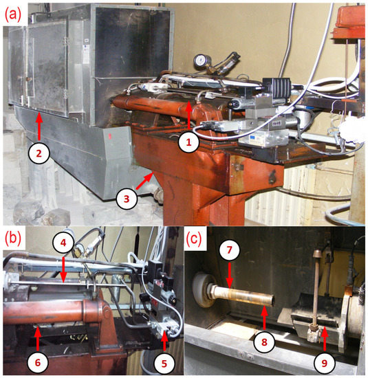
Figure 3.
Laboratory horizontal drilling stand: (a) 1—feed mechanism; 2—sheet metal cover of the working tool; 3—stand; (b) 4—slide; 5—control system for the drive spindle; 6—double acting hydraulic cylinder; (c) 7—core barrel; 8—drilling bit; 9—centering sled clamping mechanism.
The measured accompanying signal is a response to the operation of the drilling stand. It can be characterized (i.e., with some simplification) as the result of the superposition of a periodic signal derived from the activity of the stand and a periodic signal with a strong stochastic component. It is formed during the operation of individual aggregates and at the interface between the drilling tool and the rock. Research papers [29,30] present the use of vibration and acoustic signals for determining the geomechanical properties of rocks.
This research aimed to find a suitable method that would indirectly determine the state of the aggregates and the process of uncoupling the rock concerning its optimal mode. Kumar et al. [31], and Salimi and Esmaeili [32] proposed an optimal working mode of the drilling process based on the vibration signal. Such a method is the cluster analysis of the vibration signal [33,34].
In the cluster analysis of signals in the time domain, it is assumed that the sought-after information is hidden in one of the time characteristics of the signal, such as the signal period, arithmetic mean, dispersion, power, energy, or probability density distribution. Here, a distinction is made whether it is a deterministic signal or a signal with a random component. This was the first partial research task regarding the possibility of process recognition and identification.
Simultaneously analyzing the vibration signal in the time domain, its frequency analysis was also performed. As mentioned, signal processing in the frequency domain is based on the idea that any signal can be replaced by a group of simple harmonic signals, each with a different amplitude, frequency, and initial phase. Similarly, the related idea about the origin of the accompanying vibration signal is authentic. Therefore, it is possible to expect two groups of components carrying information about the current state of aggregates during operation. The first group is the harmonic components derived from operating one of the stand’s aggregates. The second group is the components caused by working two or three stand aggregates simultaneously. Changes in the frequency spectrum of the signal were investigated and calculated. The authors in [35,36] processed the measured signal in the frequency domain and estimated the dominant frequencies of the process.
In the following research stage, the scientific work focused on calculating the symptom vector from the vibration signal and searching for hidden information about the actual state of the equipment and the drilling process. Guo et al. [37] applied Fourier and wavelet transform analysis methods for vibration signals to extract the dominant frequencies in different layers of the rock mass.
3. Theoretical Background
Before the clustering process, it is necessary to determine all of the significant characteristics of the objects. Based on these data, it is then possible to start grouping the objects. The objects of the drilling stand equipment are its aggregates during operation. Therefore, it is possible to describe them using the form for n = 8. The investigated aggregates are the motor, pump, hydrogenerator, and their mutual combination during operation: a total of eight objects. The measured vibration signals define individual objects.
This accompanying vibration signal is the basis for calculating the vector of symptoms of the drilling process and the operation of the aggregates.
Given the empirical knowledge in this area, it can be concluded that the vibrational signal is deterministic with a strong random component. In the research papers [38,39], the vibration signal was processed and presented using digital methods for technical diagnostics.
From a practical point of view, a single realization (i.e., sequence) of the length of the n samples is sufficient for its processing. It is possible to obtain a sufficiently strong informational value by processing it. This realization of the vibration signal can be described as a sequence of measured samples . The authors in [40,41] designed a special acoustic sensor device for the qualitative research and monitoring of technological equipment.
Realizations of signals with a length of 16,384 samples were processed to create a vector of symptoms for scientific purposes. The effort was to design and investigate the numerical signs of the drilling stand, which would sufficiently sensitively differentiate the generated vibration signals by creating clusters from the point of view of the working mode. The authors in [42,43] present useful methods of processing vibration signals for the detection and diagnosis of mechanical systems. These symptoms can be calculated from one realization or a sequence of several consecutively measured realizations of the vibration signal. Extraction of the j-th numerical symptom from the measured realization of the signal for which samples for , is understood as the n-dimensional complex vector function:
where is the signal realization organized into a vector structure . It is necessary to design and numerically calculate several symptoms to describe the state of individual aggregates. Subsequently, m numerical signs where represents the m-component sign vector , which presents the state of the process or its parts. Equation (1) describes the extraction of symptoms from the vibration signal.
When applying mathematical abstraction, it is possible to imagine that the investigated process is located in an m-dimensional linear vector space . It is assumed that for each . It is an infinite and continuous m-dimensional vector space for which .
In industrial conditions, where the vibration signal is measured and digitized by an AD converter with limited resolution, the designed vector space of symptoms is finite. Therefore, numerically calculated symptoms are components of a symptom vector and take values from finite sets of values.
In general, the symptoms themselves have different physical dimensions and different ranges of values. One symptom can acquire huge values, and the other can be very small. Standardizing the values of the characteristic vector using statistics is necessary to avoid distortion of results due to different scales of measurement parameters during cluster analysis of multivariate data. Equation (2) can be used to standardize the values of the characteristic:
where is the unstandardized j-th symptom, calculated from the k-th signal realization; N is the number of evaluated signal realizations; is the normalized j-th symptom, calculated from the k-th realization of the signal.
It was necessary to choose a suitable metric for the feature space , which determines the distance between a pair of feature vectors to be able to accurately distinguish the individual states of the process and aggregates based on the values of the vector of symptoms. In this research, the classic Euclidean metric was used, for which (3) applies [44]:
This obtained the metric feature space of the object drilling stand and drilling process. In a broader context, it can be understood as a symptom space of the rock separation process by rotary drilling.
A vibration signal was used as the basic information signal from which the proposed numerical indicators of the condition of the drilling stand were extracted.
The essential partial task of experimental research was to design the symptom vector of the process under investigation. Laboratory experiments and measurements aimed to process the vibration signal of 16 symptoms as a probable symptom vector. An analysis of the numerical values of the symptoms depending on the drilling mode and aggregates of the horizontal experimental drilling stand was carried out. In addition, it was necessary to analyze the differentiability of vector signs concerning aggregate modes using metrics.
The proposed symptoms were numerically calculated from one realization of the realization length samples. The signal samples were measured with a sampling frequency of . The calculation was repeated for consecutive realizations of the signal. Subsequently, the symptom values calculated this way were normalized according to Equation (2). This procedure was used to analyze and compare accompanying vibration signals from the operation of individual aggregates and the drilling process. In the following text of the article, the calculation relations for the proposed symptoms are given. They were designed and calculated according to the area in which they were applied. In the time domain, vibration signal values generally change over time. As a result of the need to create a symptom vector, statistical characteristics were used as the basis.
The first proposed feature was the average value of the vibration signal . It is the value of the amplitude in the waveform of the signal calculated according to relation (4):
The average value is a symptom of the position around which the other values are more or less concentrated. The disadvantage is the high sensitivity to extreme values and the possible fictitious nature of the calculated value. The second significant feature of is the variance. It expresses the degree of variability, which provides information on how the individual observed values in the analyzed signal are scattered or describes the variability of measured values. The dispersion symptom is the average value of the squares of the deviations of the measured values of the monitored symptom from their average value. The relation (5) applies to the dispersion:
The skewness symptom expresses the size of the asymmetry of the measured signal (6).
The kurtosis symptom (7) informs whether the values of the investigated signal symptom are flatter or sharper than the values of the Gaussian curve.
Other selected characteristics were specific to the vibration signal in the time domain. The following features were proposed: the peak is the maximum distance of the wave’s top from the reference value, which is usually the x-axis (8).
The peak-to-peak symptom , which represents the difference between the maximum and minimum value. The value is the maximum distance of opposite signal peaks (9):
The symptom effective value (i.e., root mean square level (rms)), where rms is an objective value used in diagnostic regulations, determined according to relation (10):
The symptom is the energy of the signal. The energy of the accompanying vibration signal is given by the sum of the squares of the signal samples (11):
The significant symptom is the norm of the measured signal from the time waveform of the signal; thus, Equation (12) applies:
The design of the ninth symptom was based on the idea of a vector whose components are the individual sample’s realization of the signal . The norm of the vector was defined for the feature vector (13):
Specifically, the norm of the vector .
The symptom represents the signal power; thus, Equation (14) applies:
The entropy of the signal is the symptom (15):
An essential statistical characteristic in time analysis is the autocorrelation function of the measured vibration signal . The autocorrelation function represents a generalization of the mean square value. It is defined by Equation (16):
It presents periodic parts of the vibration signal , and nonperiodic ones disappear quickly. It provides information about the dependence of the values of the function at time t on the values at time . For the design of the vector symptom , the norm of the autocorrelation function of the vibrational signal was calculated. It was determined based on Equation (17):
Amplitude and power spectra were calculated in the frequency domain. Their complex values are significant for the design of the feature vector in the frequency domain. Fourier transformation was used to calculate the amplitude spectrum of the vibration signal of the drilling stand. It is defined by the integral Equation (18):
Since the signal generated by some aggregates of the drilling equipment is processed directly, a numerical method known as discrete Fourier transformation (DFT) was used. For the calculation (DFT) and to obtain the resulting amplitude spectrum, it was advisable to use the fast Fourier transform (FFT) algorithm. The DFT is defined by relation (19):
The discrete value represents the amplitude. The values and have the same physical dimension. Subsequently, the moment of the vibration signal in the frequency domain was calculated from the amplitude spectra. The moment of signal spectra as a vector symptom is a numerical characteristic that is calculated from the amplitude spectrum vibration signal. The moment symptom represents the center of gravity of the spectrum or the virtual center of the spectrum. When designing the signs for the drilling process, the moment is an essential numerical characteristic. The moment of the signal represents the sum of products of all possible values of the spectrum with the frequencies of these spectra (20).
Since the result of the FFT is a vector of complex values, a suitable symptom is also the norm of the amplitude spectrum of the signal and Equation (21) applies:
In industrial practice, power spectra are also calculated in addition to amplitude spectra. In complex industrial processes, to which the drilling process and equipment belong, power spectra have a stronger telling value about the complex state of the technological process. The Equation (22) was used to calculate the power spectrum:
where is valid for a signal in the discrete form with a finite number of samples N. On this basis, the moment of the power spectrum was calculated (23):
Subsequently, the norm of the power spectrum was calculated as , as the last proposed symptom (24).
After determining the symptoms of the aggregates, it is necessary to create clusters of objects. Clusters form a set of objects. The set of clusters for the investigated drilling stand can be written as , i.e., for n = 8. In addition, each cluster contains at least one object.
A typical symbolic representative was determined for the clusters created by the symptoms of the aggregates, which is the center of the symptom cluster. It was considered that if the objects represent points in the space, then it is possible to consider the center of gravity (centroids) of the objects in the feature cluster.
Then, for a more effective assessment of the differentiability of the vibration signal from the drill stand aggregates using a defined symptom vector, centroids (centroids) were calculated (25). Centroids were calculated for each cluster of aggregates and symptoms. They represent an essential center of a cluster of symptoms because they can have the character of an object.
where are the numerical symptoms for each and N is the number of symptoms in the set.
4. Results and Discussion
The main task of the experimental research was the design of the characteristic vector s and the determination of clusters during the operation of the drilling equipment aggregates from the vibration signal. First, the experiments were performed on 16 specific symptoms as possible elements of the symptom vector. Then, an analysis was conducted of the values of these symptoms depending on the activity of the aggregates on the horizontal drilling stand. In addition, it was necessary to analyze the differentiability of individual symptoms using the Euclidean metric.
The symptoms were always numerically calculated from one realization of the signal with the length of the realization of samples and measured with a sampling frequency = 18 kHz.
All proposed symptoms were calculated from realizations of the vibration signal from the operation of aggregates and normalized according to the Equation (2). It was necessary to look for significantly different symptoms that fundamentally differentiate the operation of aggregates, engine, pump, hydrogenerator, or their combined operation. Another point of view is the effort to exclude common symptoms, unimportant or redundant. The following variables were proposed as state indicators of the aggregates based on laboratory experiments: —mean value (i.e., measure of variability); —variance of the signal time waveform; —skewness; —kurtosis; —peak (i.e., maximum value); —peak2peak; —rms of the signal; —Lx norm of signal time waveform; —signal energy; —signal power; —signal entropy; — autocorrelation norm; — moment of the signal spectrum; — norm of the signal spectrum; — moment of the power spectrum of the signal; — norm of the power spectrum of the signal.
Due to the large number of results obtained by signal processing, only significant results are presented in this paper.
Figure 4 shows individual symptoms , , , of the vibration signal of all aggregates. It is possible to assess the good differentiability of the signals from the display of the symptom waveforms. The biggest recognizable differences are the mean value for the symptom (see Figure 4a). Waveforms of symptoms show strong fluctuations. The highest symptom values have the pump and the hydro generator. On the contrary, the lowest values are during the motor and pump, motor, and hydrogenerator operation. Symptoms and partially have the same waveform (see Figure 4b,c). A greater difference is in the -skewness symptom, which divides the waveforms into two groups. The first group is the aggregates pump, hydrogenerator, and their joint operation. The second group consists of the activity of the other aggregates, while the motor aggregate has the largest values (see Figure 4d). All symptoms were calculated with statistical characteristics.
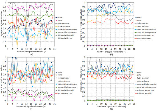
Figure 4.
Waveforms of values of selected symptoms of all aggregates , , , : (a) symptom —mean values; (b) symptom —dispersion values; (c) symptom —kurtosis values; (d) symptom —maximum values.
Figure 5 shows the waveform of symptoms , , , and . A more detailed description is required (see Figure 5a) with the waveforms of the symptom —rms. It is clear that the symptom strongly divides the aggregates into two groups again. Similarly to , , and , the first group consists of a pump, hydrogenerator, and their combination. Their symptom values are lower than those of the other aggregates. From this point of view, it can be assumed that the symptom is significant for the recognition and classification of vibration signals. Symptoms , , and are strongly fluctuating in values. The pump has the highest symptom value —entropy. However, the values fluctuate strongly. It is different for the hydrogenerator, which has high but relatively constant values of the symptom (see Figure 5b). At and , the aggregate-separated motor has the highest values, and a pump and hydrogenerator have the lowest (see Figure 5c,d). Symptoms , , and belong to the specific characteristics of the vibration signal, and symptom is calculated from the frequency characteristic.
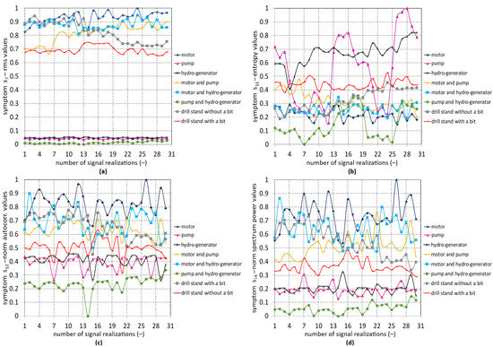
Figure 5.
Waveforms of values of selected symptoms of all aggregates , , , : (a) symptom —rms value; (b) symptom —entropy values; (c) symptom —norm autocorrelation values; (d) symptom —norm spectrum power values.
The presented different waveforms of symptoms provide a good basis for creating clusters, which aim to recognize and classify vibration signals from the operation of the drilling stand aggregates.
Among the less suitable symptoms based on their waveforms, it is possible to choose , i.e., skewness and , i.e., the moment of the signal spectrum (see Figure 6). The values of the symptom , i.e., the skewness, oscillate vigorously. Assessing the maximum and minimum values is complicated, and the differences between individual aggregates are negligible (see Figure 6a). At the symptom , i.e., the moment of the signal spectrum, two groups of objects are visible (see Figure 6b). The first group consists of a pump, a hydrogenerator, and their joint operation. However, the waveforms overlap so strongly that it is impossible to assess their difference. The second group of objects consists of other aggregates. It is possible to distinguish them partially but not significantly.
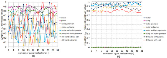
Figure 6.
Waveforms of values of selected symptoms of all aggregates , : (a) symptom —skewness values; (b) symptom —moment spectrum values.
The important results and indicators are the presentation of the waveform of the symptom values for one aggregate of the drilling stand. Therefore, their plot is essential from the point of view of efficiency of the classification and differentiability of the sought symptoms (see Figure 7, Figure 8, Figure 9, Figure 10, Figure 11, Figure 12, Figure 13 and Figure 14).
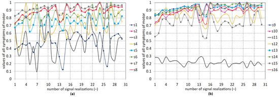
Figure 7.
Motor as the aggregate: (a) symptom values –; (b) symptom values –.
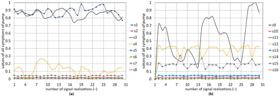
Figure 8.
Pump as the aggregate: (a) symptom values –; (b) symptom values –.
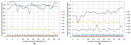
Figure 9.
Hydrogenerator as aggregate: (a) symptom values –; (b) symptom values –.
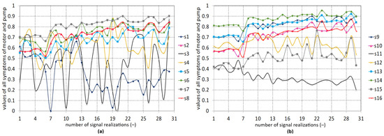
Figure 10.
Motor and pump as aggregates: (a) symptom values –; (b) symptom values –.
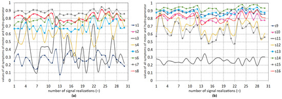
Figure 11.
Motor and hydrogenerator as aggregates: (a) symptom values –; (b) symptom values –.
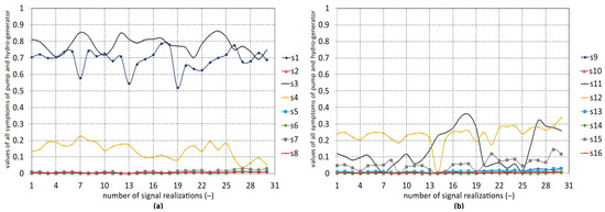
Figure 12.
Pump and hydrogenerator as aggregates: (a) symptom values –; (b) symptom values –.
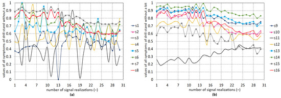
Figure 13.
All stand aggregates without drill bit: (a) symptom values –; (b) symptom values –.
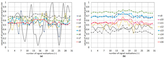
Figure 14.
All stand aggregates with drill bit: (a) symptom values –; (b) symptom values –.
Plotting all motor symptoms in Figure 7 gives a partial idea of the possibility of clustering for a single aggregate. For example, from Figure 7b, it can be concluded that has the lowest values, other symptoms for the motor are not fully pronounced, and their values are relatively high, such as and (see Figure 7a).
Figure 8 shows all the symptoms for the pump. From Figure 8a, it can be concluded that the symptoms have relatively low values except for and . A similar situation is seen in Figure 8b where , , and have higher values. The other symptoms for the pump are not significant.
Figure 9a,b show all the symptoms for the hydrogenerator. A similar symptom analysis applies to the hydrogenerator as to the pump.
From Figure 10a,b of the operation of the motor and pump, it is possible to draw the partial conclusion that the symptoms are well differentiated and have a constant waveform. The exceptions are and .
From Figure 11a,b, which show the operation of the motor and hydrogenerator, it is possible to derive a similar partial result as that for the motor and pump operation. The motor and its vibration signal represent an aggregate that, by its operation, fundamentally affects the vibration signals and symptoms of the other units, such as the pump and hydrogenerator.
The presentation of symptoms for the operation of the pump and the hydrogenerator are similar to those for the pump and the hydrogenerator in their separate operation. Most symptoms have low values, and there are few differences (Figure 12a,b).
From Figure 13a,b, it can be concluded that individual symptom differences are good if all aggregates are active. A strong fluctuation is only observed for .
From Figure 14a,b, it is possible to see that the difference in symptoms is very good in the operation of all aggregates if the drill bit is installed. There is a strong fluctuation at and partly at . Overall, it is possible to draw a partial conclusion that the designed symptoms and the created symptom vectors are suitable criteria for classifying the objects of the drill stand. It was assumed that it will be possible to create clusters based on the analysis, description, and visualization.
Figure 15 shows the positions of the symptom vectors of the objects in the two-dimensional symptom plane that form individual clusters. Clusters of objects form calculated symptoms from N = 30 realizations of the vibration signal of all aggregates. Individual aggregates as objects (i.e., ) of the drilling stand have their own defined part of the symptom space. However, the border between them is not sharp, and there is mutual overlap and the emergence of penetrations between clusters. When viewed in a two-dimensional symptom plane with symptoms and , five clusters can be formed (see Figure 15a). Relatively good differentiability of clusters is possible for aggregates such as the motor (C), the motor and hydrogenerator (C), the drilling stand without a drill bit (C), and the drilling stand with a drill bit (C). The cluster (C) represents a group of pump aggregates, the hydrogenerator, and their joint activity. Creating their separate clusters is not quite possible. Creating a cluster for the motor and pump unit together as an object is impossible because its symptoms are extensive. Symptom values were found in multiple clusters. Figure 15b shows the symptoms and in the symptom plane. The significance of the partial results is that it is possible to create clusters from the objects of the pump (C), hydrogenerator (C), and their joint activity (C). Partial recognizability of objects through the clusters was noted for the motor and hydrogenerator (C), the drill stand without a drill bit (C), and the drill stand with a drill bit (C). The motor and the motor and pump together were hard to recognize. Similar results were obtained for symptoms and shown in the plane in Figure 15c and for symptoms , (see Figure 15d). Common features represent the possibility of creating a cluster (C) and further clusters (C, C, C,C). Another feature is a different distribution in the symptom plane.
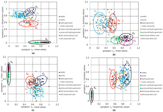
Figure 15.
Cluster graphs of all objects in two-dimensional symptom space with symptoms , , , : (a) graph of symptoms and in the plane; (b) graph of symptoms symptoms and in the plane; (c) graph of symptoms and in the plane; (d) graph of symptoms and in the plane.
A similar cluster analysis was performed and is presented in Figure 16 for symptoms , , , and . In Figure 16a, four clusters are formed, of which well-recognizable objects are marked as (C, C, C). The combination of the representation from the symptoms and does not allow the creation of separate clusters for the other aggregates, so they were labeled as C because they contain other objects than C. In the next combination of symptoms, and , the clusters from the previous partial results were confirmed (see Figure 16b). The best results were obtained with the and . It was possible to recognize seven clusters of objects in Figure 16c based on the symptoms. The unrecognizable object is just the motor and the pump working together. This combination of symptoms and determination of clusters of objects represents a significant achievement in identifying and classifying the drill stand and its aggregates. The opposite case is shown in Figure 16d with symptoms and . It can be seen that only four clusters could be formed. The significance is that these were clusters (i.e., C, C, and C) for aggregates considered as objects (i.e., ) that are weakly or hardly recognizable in other symptoms. All other objects form another cluster (C). It is also important that the results of displaying the clusters in the plane represent a variant in which the symptoms are from different areas of signal processing. While the symptom norm of autocorrelation of the signal is calculated in the time domain, the symptom is in the frequency domain. The fact that the autocorrelation function of the signal and its power spectrum are equivalent and mutually transformable characteristics of the process also plays a role here. However, their numerical form in the structure of the symptom vector from which they are calculated is different.
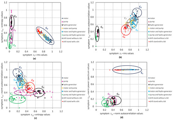
Figure 16.
Cluster graphs of all objects in the two-dimensional symptom space with symptoms , , , : (a) graph of symptoms and in the plane; (b) graph of symptoms and in the plane; (c) graph of symptoms and in the plane; (d) graph of symptoms and in the plane.
The selected and displayed symptoms of objects and the created clusters in a two-dimensional plane are significant partial results from the presented research. They provide valuable information about suitable symptoms for forming clusters and classifying the drill stand’s objects.
In the following section of the paper, Figure 17 shows the clusters of symptom vectors of the drill stand aggregates in the three-dimensional symptom space. For such a display, three symptoms were used, making it possible to assume the differentiability of the aggregates. From the many research results, only the representative ones were selected. This three-dimensional representation comprised the following symptoms, i.e., —mean values; —dispersion values; —energy values (see Figure 17a). There was sufficient diversity of the uniform clusters of aggregates created (i.e., C, C, C, C, C, and C). A cluster could not be created for the hydrogenerator, motor, and pump objects. This makes their classification more difficult. For Figure 17b, where the symptoms (i.e., —energy values; —entropy values; and -norm autocorrelation values) were displayed, it was possible to, at least partially, display the cluster (i.e., C—for the motor and pump together) despite being located between the two defined C and C. Similar results are provided in Figure 17c,d.
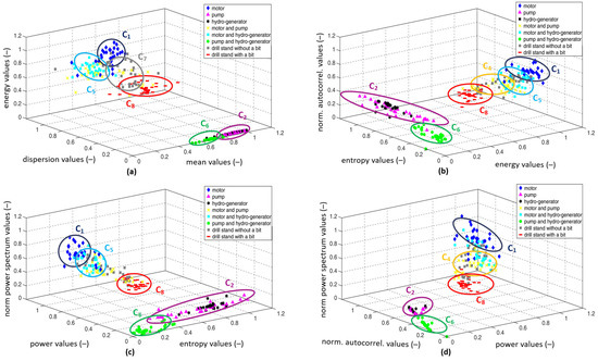
Figure 17.
Clusters of symptom vectors of the drill stand aggregates in a three-dimensional symptom space: (a) graph of symptoms: mean, dispersion, and energy values in space; (b) graph of symptoms: energy, entropy, and norm autocorrelation values in space; (c) graph of symptoms: entropy, power and norm power spectrum values in space; (d) graph of symptoms: power, norm autocorrelation and norm power spectrum values in space.
Partial results are also presented in Figure 18a–d. Identified clusters of aggregates can be seen, which means that the differentiability is sufficient. It was stated that six clusters of drill stand aggregates were defined. However, the boundaries between clusters are strongly blurred. Nevertheless, the resulting clusters indicate that the calculated symptoms from the vibration signal measurement are suitable for classification.
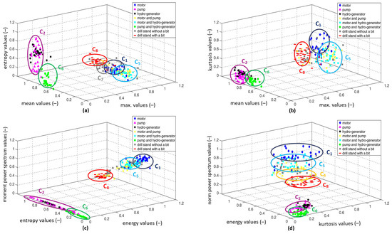
Figure 18.
The location of clusters of symptom vectors of the drill stands aggregates in three-dimensional symptom space: (a) graph of symptoms: maximum, mean, and entropy values in space; (b) graph of symptoms: maximum, mean, and kurtosis in space; (c) graph of symptoms: energy, entropy, and moment power spectrum values in space; (d) graph of symptoms: kurtosis, energy, and norm power spectrum values in space.
Suppose one compares symptom display and cluster formation in the vector plane and space; in that case, it can be concluded that visualization in space gives a more effective and detailed view of the position (i.e., location in space), character (i.e., a span in space), and mutual overlap.
Another option for assessing the differentiability of aggregates when using a defined symptom vector is based on the cluster’s calculated center of gravity (i.e., centroid). Figure 19 shows the centroids of individual clusters, representing an essential representative center in the cluster. Centroids are displayed in three-dimensional symptom space. The distribution of centroids in three-dimensional space confirms the formation of clusters in their vicinity.
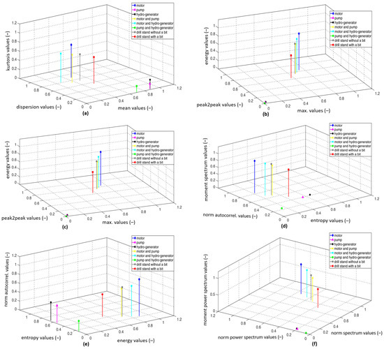
Figure 19.
Centroids of the symptoms of the aggregates as objects in a three-dimensional symptom vector: (a) symptom centroids: mean, dispersion, and kurtosis values; (b) symptom centroids: maximum, peak2peak, and energy values; (c) symptom centroids: norm, power, and rms values; (d) symptom centroids: entropy, norm autocorrelation, and moment spectrum values; (e) symptom centroids: energy, entropy, and norm autocorrelation values; (f) symptom centroids: norm spectrum, norm power spectrum, and moment power spectrum.
Table 1 shows the centroid values of individual objects. Table 2, Table 3, Table 4, Table 5, Table 6 and Table 7 show the calculated distances between the centroids of the clusters in the three-dimensional feature space. The present research solves the identification of symptoms, classification, and recognition of clusters of aggregates of the laboratory horizontal drilling stand. The starting point of the research was processing the accompanying vibration signal for the cluster analysis. The differentiability of eight objects proves the appropriateness of the proposed symptoms.

Table 1.
Centroid values of individual objects.

Table 2.
Distances between the centroids of the clusters in the three-dimensional feature space.

Table 3.
Distances between the centroids of the clusters in the three-dimensional feature space.

Table 4.
Distances between the centroids of the clusters in the three-dimensional feature space.

Table 5.
Distances between the centroids of the clusters in the three-dimensional feature space.

Table 6.
Distances between the centroids of the clusters in the three-dimensional feature space.

Table 7.
Distances between the centroids of the clusters in the three-dimensional feature space.
The goal of this and future research will be oriented towards controlling the rock drilling process and drilling equipment so that the mode of operation is economically efficient and environmentally acceptable.
5. Conclusions
This paper follows previous research work in obtaining and processing raw materials and processing the signals from the process of rotary disintegrating of rocks. The problem of the proposal of symptoms and the classification of aggregates as objects of laboratory drilling equipment was solved. Sixteen symptoms were investigated, designed, and numerically calculated based on the vibration signal. The accompanying vibration signal was measured as an integrating information source of their activity. Visualization in the symptom and space plane made classifying the searched clusters of objects possible. The created clusters of objects confirmed the classifiability based on the measured vibration signal and its calculated symptoms. The results of scientific research present sufficient differentiability of drilling equipment objects. Overall, the applied method offers great potential in the search for additional symptoms by optimizing the symptom dimension. Extraction of significant symptoms and exclusion of redundant ones will be important. Representative results were demonstrated for symptoms such as , , , , , and . Weakly satisfactory results were obtained for symptoms and . The main contributions of this scientific study are:
- A drill stand was presented as an object of research and related measurements;
- A cluster analysis method was proposed for the classification of drilling stand aggregates;
- Specific symptoms of the vibration signal in the time and frequency domain and the creation of the symptom vector were designed and calculated;
- The effectiveness of the classification of aggregates based on centroids and their mutual distances was analyzed;
- The creation of classifiable clusters of aggregates;
- Displaying clusters of aggregates in 2D and 3D graphs.
Searching for additional symptoms is possible in the cepstral and wavelet analysis of signals. Promising research can be undertaken in the application of clustering using fuzzy sets. This research aimed to identify a sufficient number of clusters from the point of view of the equipment’s effective mode during the aggregates’ operation. Under the effective mode, the setting of optimal drilling parameters (i.e., revolutions and pressure force), wear of the drill bit and aggregates, drilling speed, and energy consumption are understood. Experimental measurements were performed in laboratory conditions, where the working environment was controlled, from the technical condition of the equipment to the drilled rock. However, various emergency conditions can occur in the industrial practice of geotechnical engineering. Therefore, future research will be oriented towards experiments in real conditions. These will provide information that is more reflective of real geoengineering applications.
Author Contributions
Conceptualization, P.F., R.F. and J.K.; Data curation, P.F. and R.F.; Formal analysis, M.D. and M.L.; Methodology, P.F. and J.K.; Project administration, P.F.; Resources, M.D. and M.L.; Supervision, M.D. and M.L.; Validation, M.D.; Writing—Original draft preparation, P.F., R.F. and J.K.; Writing—review and editing J.K. All authors have read and agreed to the published version of the manuscript.
Funding
This work was supported by the Cultural and educational grant agency of the Ministry of Education, science, research and sport of the Slovak Republic under grant KEGA 010TUKE-4/2023 “Application of educational robots in the process of teaching the study program industrial logistics”.
Institutional Review Board Statement
Not applicable.
Informed Consent Statement
Not applicable.
Data Availability Statement
Not applicable.
Acknowledgments
We appreciate the support from the Cultural and educational grant agency of the Ministry of Education, science, research and sport of the Slovak Republic under grant KEGA 010TUKE-4/2023 “Application of educational robots in the process of teaching the study program industrial logistics”.
Conflicts of Interest
The authors declare no conflict of interest.
References
- Sekula, F.; Koči, M.; Bejda, J.; O. Krajecová, O. The drilling stand research in optimization issues of diamond drilling, Standový výskum v problematike optimalizácie diamantového vŕtania. Geol. Prieskum 1976, 6, 169–173. [Google Scholar]
- Hood, M.; Alehossein, H. A development in rock cutting technology. Int. J. Rock Mech. Min. Sci. 2000, 37, 297–305. [Google Scholar] [CrossRef]
- Tiryaki, B.; Dikmen, A.C. Effects of Rock Properties on Specific Cutting Energy in Linear Cutting of Sandstones by Picks. Rock Mech. Rock Eng. 2005, 39, 89–120. [Google Scholar] [CrossRef]
- Qi, G.; Zhengying, W.; Junhui, R. New rock material definition strategy for FEM simulation of the rock cutting process by TBM disc cutters. Tunn. Undergr. Space Technol. 2017, 65, 179–186. [Google Scholar] [CrossRef]
- Chlebová, Z. Simulation analysis of vibratory device controlled vibration. Acta Mech. Slovak. 2008, 12, 323–334. [Google Scholar]
- Atici, U.; Ersoy, A. Correlation of specific energy of cutting saws and drilling bits with rock brittleness and destruction energy. J. Mater. Process. Technol. 2009, 209, 2602–2612. [Google Scholar] [CrossRef]
- Trefová, L.; Lazarová, E.; Krúpa, V. Application of fuzzy methods in tunnelling. Acta Montan. Slovaca 2011, 16, 197–208. [Google Scholar]
- Mirani, A.A.; Samuel, R. Discrete vibration stability analysis with hydromechanical specific energy. J. Energy Resour. Technol. Trans. ASME 2018, 140, 032904. [Google Scholar] [CrossRef]
- Krepelka, F.; Chlebová, Z.; Ivaničová, L. Measurement, analyzes and evaluation of stochastic processes operating in rock drilling. Acta Mech. Slovak. 2008, 12, 229–236. [Google Scholar]
- Flegner, P.; Kačur, J.; Durdán, M.; Leššo, I.; Laciak, M. Measurement and processing of vibro-acoustic signal from the process of rock disintegration by rotary drilling. Measurement 2014, 56, 178–193. [Google Scholar] [CrossRef]
- Qiu, H.; Yang, J.; Butt, S.; Zhong, J. Investigation on random vibration of a drillstring. J. Sound Vib. 2017, 406, 74–88. [Google Scholar] [CrossRef]
- Klaic, M.; Murat, Z.; Staroveski, T.; Brezak, D. Tool wear monitoring in rock drilling applications using vibration signals. Wear 2018, 408–409, 222–227. [Google Scholar] [CrossRef]
- Kessai, I.; Benammar, S.; Doghmane, M.Z.; Tee, K.F. Drill bit deformations in rotary drilling systems under large-amplitude stick-slip vibrations. Appl. Sci. 2020, 10, 6523. [Google Scholar] [CrossRef]
- Shreedharan, S.; Hegde, C.; Sharma, S.; Vardhan, H. Acoustic fingerprinting for rock identification during drilling. Int. J. Min. Miner. Eng. 2014, 5, 89–105. [Google Scholar] [CrossRef]
- Khoshouei, M.; Bagherpour, R.; Jalalian, H. Rock Type Identification Using Analysis of the Acoustic Signal Frequency Contents Propagated While Drilling Operation. Geotech. Geol. Eng. 2022, 40, 1237–1250. [Google Scholar] [CrossRef]
- Buatoom, U.; Jamil, M.U. Improving Classification Performance with Statistically Weighted Dimensions and Dimensionality Reduction. Appl. Sci. 2023, 13, 2005. [Google Scholar] [CrossRef]
- Flegner, P.; Kačur, J.; Durdán, M.; Laciak, M. Evaluation of the Acceleration Vibration Signal for Aggregates of the Horizontal Drilling Stand. Appl. Sci. 2022, 12, 3984. [Google Scholar] [CrossRef]
- Sharif, W.; Mumtaz, S.; Shafiq, Z.; Riaz, O.; Ali, T.; Husnain, M.; Choi, G. An Empirical Approach for Extreme Behavior Identification through Tweets Using Machine Learning. Appl. Sci. 2019, 9, 3723. [Google Scholar] [CrossRef]
- Piltan, F.; Kim, J.M. Bearing anomaly recognition using an intelligent digital twin integrated with machine learning. Appl. Sci. 2021, 11, 4602. [Google Scholar] [CrossRef]
- Adolfo, C.M.S.; Chizari, H.; Win, T.Y.; Al-Majeed, S. Sample Reduction for Physiological Data Analysis Using Principal Component Analysis in Artificial Neural Network. Appl. Sci. 2021, 11, 8240. [Google Scholar] [CrossRef]
- Cao, A.; Liu, Y.; Yang, X.; Li, S.; Liu, Y. FDNet: Knowledge and Data Fusion-Driven Deep Neural Network for Coal Burst Prediction. Sensors 2022, 22, 3088. [Google Scholar] [CrossRef] [PubMed]
- Zhang, P.; Li, X.; Chen, J. Prediction Method for Mine Earthquake in Time Sequence Based on Clustering Analysis. Appl. Sci. 2022, 12, 11101. [Google Scholar] [CrossRef]
- Raubitzek, S.; Neubauer, T. A fractal interpolation approach to improve neural network predictions for difficult time series data. Expert Syst. Appl. 2021, 169, 114474. [Google Scholar] [CrossRef]
- Chongfuangprinya, P.; Kim, S.B.; Park, S.K.; Sukchotrat, T. Integration of support vector machines and control charts for multivariate process monitoring. J. Stat. Comput. Simul. 2011, 81, 1157–1173. [Google Scholar] [CrossRef]
- Chiang, L.E.; Elías, D.A. Modeling impact in down-the-hole rock drilling. Int. J. Rock Mech. Min. Sci. 2000, 37, 599–613. [Google Scholar] [CrossRef]
- Xanthopoulos, P.; Razzaghi, T. A weighted support vector machine method for control chart pattern recognition. Comput. Ind. Eng. 2014, 70, 134–149. [Google Scholar] [CrossRef]
- Arena, S.; Manca, G.; Murru, S.; Orrú, P.F.; Perna, R.; Reforgiato Recupero, D. Data Science Application for Failure Data Management and Failure Prediction in the Oil and Gas Industry: A Case Study. Appl. Sci. 2022, 12, 10617. [Google Scholar] [CrossRef]
- Flegner, P.; Kačur, J.; Durdá, M.; Laciak, M. Processing a measured vibroacoustic signal for rock type recognition in rotary drilling technology. Measurement 2019, 134, 451–467. [Google Scholar] [CrossRef]
- Zhao, X.X.; Gong, Y.D. Research on the Load on Cutter Head of Hard Rock Tunnel Boring Machine. Appl. Mech. Mater. 2014, 684, 303–307. [Google Scholar] [CrossRef]
- Khoshouei, M.; Bagherpour, R. Predicting the Geomechanical Properties of Hard Rocks Using Analysis of the Acoustic and Vibration Signals During the Drilling Operation. Geotech. Geol. Eng. 2021, 39, 1–13. [Google Scholar] [CrossRef]
- Kumar, R.; Kumaraswamidhas, L.A.; Murthy, V.M.S.R.; Vettivel, S.C. Experimental investigations on machine vibration in blast-hole drills and optimization of operating parameters. Meas. J. Int. Meas. Confed. 2019, 145, 803–819. [Google Scholar] [CrossRef]
- Salimi, A.; Esmaeili, M. Utilising of linear and non-linear prediction tools for evaluation of penetration rate of Tunnel Boring Machine in hard rock condition. Int. J. Min. Miner. Eng. 2013, 4, 249. [Google Scholar] [CrossRef]
- He, Z.; Cheng, W.; Xia, J.; Wen, W.; Li, M. Vibration source signal separation of rotating machinery equipment and robot bearings based on low rank constraint. Appl. Sci. 2021, 11, 5250. [Google Scholar] [CrossRef]
- Tiboni, M.; Remino, C.; Bussola, R.; Amici, C. A Review on Vibration-Based Condition Monitoring of Rotating Machinery. Appl. Sci. 2022, 12, 972. [Google Scholar] [CrossRef]
- Akçay, H. Spectral estimation in frequency-domain by subspace techniques. Signal Process. 2014, 101, 204–217. [Google Scholar] [CrossRef]
- Fernández-Ros, M.; Parra, J.A.G.; Salvador, R.M.G.; Castellano, N.N. Optimization of the periodogram average for the estimation of the power spectral density (PSD) of weak signals in the ELF band. Measurement 2016, 78, 207–218. [Google Scholar] [CrossRef]
- Guo, G.; Zhao, H.; Qi, Z.; Hu, C.; Zhao, B.; Wang, S. Experiment Analysis of Drilling Feedback Signal from Simulation of Roadway Roof. Geofluids 2022, 2022, 1471264. [Google Scholar] [CrossRef]
- Prasad, B.S.; Babu, M.P. Correlation between vibration amplitude and tool wear in turning: Numerical and experimental analysis. Eng. Sci. Technol. Int. J. 2017, 20, 197–211. [Google Scholar] [CrossRef]
- Zhu, D.C.; Zhang, Y.X.; Zhu, Q.W. Fault Diagnosis Method for Rolling Element Bearings Under Variable Speed Based on TKEO and Fast-SC. J. Fail. Anal. Prev. 2018, 18, 2–7. [Google Scholar] [CrossRef]
- Wang, K.; Hu, Y.; Yang, K.; Qin, M.; Li, Y.; Liu, G.; Wang, G. Experimental evaluation of rock disintegration detection in drilling by a new acoustic sensor method. J. Pet. Sci. Eng. 2020, 195, 107853. [Google Scholar] [CrossRef]
- Sierra-Alonso, E.F.; Caicedo-Acosta, J.; Gutiérrez, A.A.O.; Quintero, H.F.; Castellanos-Dominguez, G. Short-time/-angle spectral analysis for vibration monitoring of bearing failures under variable speed. Appl. Sci. 2021, 11, 3369. [Google Scholar] [CrossRef]
- Shim, J.; Kim, G.; Cho, B.; Koo, J. Application of vibration signal processing methods to detect and diagnose wheel flats in railway vehicles. Appl. Sci. 2021, 11, 2151. [Google Scholar] [CrossRef]
- Krajňák, J.; Homišin, J.; Grega, R.; Kaššay, P.; Urbanský, M. The failures of flexible couplings due to self-heating by torsional vibrations—validation on the heat generation in pneumatic flexible tuner of torsional vibrations. Eng. Fail. Anal. 2021, 119, 104977. [Google Scholar] [CrossRef]
- Du, S.; Lv, J. Minimal Euclidean distance chart based on support vector regression for monitoring mean shifts of auto-correlated processes. Int. J. Prod. Econ. 2013, 141, 377–387. [Google Scholar] [CrossRef]
Disclaimer/Publisher’s Note: The statements, opinions and data contained in all publications are solely those of the individual author(s) and contributor(s) and not of MDPI and/or the editor(s). MDPI and/or the editor(s) disclaim responsibility for any injury to people or property resulting from any ideas, methods, instructions or products referred to in the content. |
© 2023 by the authors. Licensee MDPI, Basel, Switzerland. This article is an open access article distributed under the terms and conditions of the Creative Commons Attribution (CC BY) license (https://creativecommons.org/licenses/by/4.0/).