Abstract
This paper analyzes and calculates the mechanical properties of composite tape spring structures during folding and bending and establishes a non-linear control equation for the folding and bending of composite laminate tape spring structures. Accurate expressions for folding and bending displacements are obtained. The influence of the cross-section’s central angle and the composite tape spring’s ply thickness on their mechanical properties are analyzed. Finite element numerical analysis is performed on [−45 45]s laminated composite tape springs, and the correctness of the theoretical derivation is proved by comparing the curvature radius-bending moment curve. Based on previous research, the mechanical properties of different tape spring materials and structures are compared, further studying the lightweight design of space deployment mechanisms. The results show that the steady-state bending moment performance of composite tape springs is excellent, with a 162.1% improvement in steady-state bending moment performance per unit mass compared to traditional metallic tape springs. Additionally, the critical bending moment performance of negative Poisson ratio honeycomb structure tape springs is also excellent, with a 62.3% improvement in steady-state bending moment performance per unit mass compared to traditional metallic tape springs.
1. Introduction
In recent times, the tape spring has garnered increasing attention due to its advantageous engineering characteristics. Notably, structures constructed from tape springs possess a multitude of beneficial features, including a low mass, uncomplicated mechanics, high efficiency of enfoldment, and an absence of mechanical joints. Moreover, they are capable of spontaneous deployment without requiring external driving forces [1,2]. While conventional tape springs made from metallic materials such as beryllium-copper or high-strength steel have been utilized in space deployable structures for several decades, the demand for cheaper, simpler, and more reliable deployable structures has brought carbon fiber reinforced plastic (CFRP) tape springs to the fore. Such springs are increasingly gaining prominence owing to their tailorable performance, low mass, and low coefficient of thermal expansion [3]. Short leaf springs are used for automatic locking in the deployed state, as shown in Figure 1, such as the locking mechanism of solar sails. Long tape springs are used to deploy space antennas, as shown in Figure 2. The tape spring driving mode belongs to a passive driving mode. The tape spring components are arranged according to the design requirements at the mechanism members’ or rods’ nodes or midpoints. When folded, the spring stores elastic potential energy due to pre-stress. After the mechanism is unlocked, the spring releases the energy, and the mechanism is deployed. Tape spring structures include single tape springs, two tape springs, and more tape springs [4].
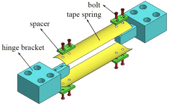
Figure 1.
Applications of tape spring structures [5].
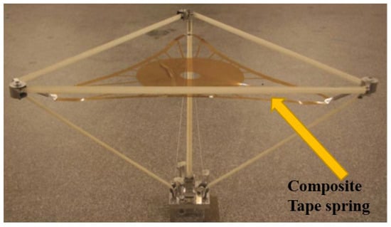
Figure 2.
Applications of composite tape spring structures [6].
K. A. Seffen [7,8,9] studied the folding and unfolding performance of single-tape springs and double-tape springs, analyzed their unfolding behavior, and derived the relationship between the curvature radius and the driving moment during the bending process. Scott J. I. Walker [10] provided a photography method to study the post-buckling curvature at the folding position, including two-dimensional (2D) and three-dimensional (3D) analyses. The results revealed the strain distribution at the folding position of the tape hinge, which generates an opening moment related to the curvature, making the modeling of unfolding using these hinges more accurate. Wei Chang [11] studied the influence of different geometric parameters on the mechanical properties of tape springs, especially on their driving and anti-interference capabilities during the bending process. This provides reference values to improve the kinematic accuracy and reliability of deployable structures. Lan Xin et al. [12] studied the shape memory polymer composites (SMPC) reinforced by carbon fiber fabric and thermosetting styrene-based matrix. They demonstrated the feasibility of using SMPC hinges as deployable structures. The main advantage of shape memory polymers (SMP) is their high recovery rate, low density, and low cost. Oberst S et al. [13] verified experimentally the response of a thin-wall flexible structure represented by tape spring under static and vibrational loads and compared the material parameters of single-curved and double-curved surface designs. Yang H [14] studied the folding and unfolding behavior of single-layer and double-layer tape spring hinges by analyzing numerical and experimental methods. They also explored the establishment of a surrogate model for a multi-layer tape spring (MLTS) hinge using response surface methodology (RSM) and the solution of multi-objective optimization design problems using a modified non-dominated sorting genetic algorithm (NSGA-II). Wang et al. [15] embedded strain gauged in the bistable composite tape springs and obtained the change of strain during the bending and folding process of the bistable composite tape springs. Elsheikh A [16] investigated the energy storage performance of bistable composite tape spring structures and optimized and predicted their response under different driving schemes using artificial intelligence techniques. Kajihara [17] studied the influence of cross-sectional geometric dimensions on the loading efficiency and unfolding behavior of bistable composite tape springs and found that bistable performance is lost under certain dimensions. Yang [18] developed a novel optimization methodology for the design of TRAC boom wraps, utilizing response surface theory as well as a parametric investigation of the geometric parameters that influence the wrap behavior and deployment stability. Meanwhile, Yao [19] implemented an innovative sensor system capable of in situ validation of the structural integrity of deployable tape-spring hinges. Notably, the system leverages an ultra-thin and soft electronic skin, and the study provides an in-depth analysis of the design, fabrication, and materials of this cutting-edge technology. Whilst significant strides have been made in understanding the bending-torsion behavior of traditional metallic tape springs, the mechanical behavior of CFRP tape springs is notably more intricate, attributed to their anisotropic material properties. As such, this paper acknowledges the complexity inherent to CFRP tape springs and employs thin shell theory to consider geometric nonlinearity in the derivation of a formula for the calculation of the bending moment of such springs. This formula is subsequently applied for practical design purposes, and a finite element model is established to confirm the accuracy of the derived formula. In our previous study [20], we analyzed the substitution effect of negative Poisson honeycomb structures for tape spring structures and conducted theoretical analysis and finite element simulation to investigate the folding and bending process of the negative Poisson ratio honeycomb structure. A comparison is made using the unit mass index, and the results show that the honeycomb structure exhibits superior mechanical properties per unit mass compared to the conventional spring steel structure. This achievement contributes to the lightweight design of space deployment mechanisms. In this paper, we further compare the mechanical properties of tape spring structures with different structures and materials, optimize the design of tape spring structures, for space deployable structures, lightweight design is crucial while ensuring the functionality of deployment. This paper focuses on the lightweight requirements of space-deployable mechanisms and investigates the mechanical performance of different structural and material tape springs. and seek the optimal mechanical performance of tape spring structures.
2. Theoretical Analysis
The main purpose of this section is to establish the non-linear control equation for the folding and bending of composite tape springs, derive the precise expressions of the z-direction displacement w and steady-state bending moment during the folding and bending of composite tape springs, analyze the factors affecting the bending moment, obtain the moment–curvature characteristic curve, and carry out finite element numerical calculations and analyses. Figure 3 is a schematic diagram of a composite tape spring, where L is the length of the cylindrical shell along the generatrix direction, R is the radius of curvature of the surface in the open shell, t is the shell thickness, and θ is the opening angle. Figure 4 is a schematic diagram of the folding and bending of the cylindrical shell deployable mechanism, where M is the folding and bending moment, r is the curvature radius of the bending point after folding and bending, and φ is the opening angle of the generatrix after folding and bending.
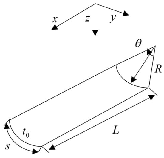
Figure 3.
Schematic diagram of the geometry of composite tape spring cylindrical shell.
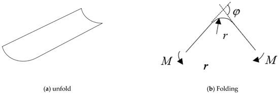
Figure 4.
Schematic diagram of folding and bending of composite tape spring cylindrical shell.
The bending and folding form is shown in Figure 4b, with a bending and folding rotation angle of and a radius of curvature of r. Establishing the coordinate system is shown in the figure, the deformation after bending and folding is shown in Figure 5a, and the analysis is carried out using the infinitesimal element.
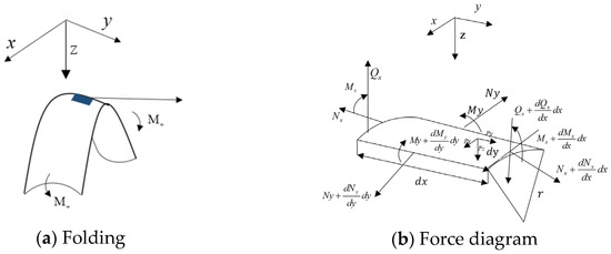
Figure 5.
Force diagram of the infinitesimal element of folding and bending of composite tape spring.
For composite structures, a cylindrical coordinate system is used. Assuming that the membrane force per unit width of the shell is N(), the internal bending force per unit width is M(), the mid-plane strain is , and the mid-plane deflection is (), the conversion is conducted.
Equilibrium equation:
Geometric equation:
Let , then
Constitutive equation:
Expression for internal force in the mid-surface:
For composite tape springs, commonly used layer configurations are symmetric layups, so
Substituting into the equilibrium equation:
Simplify:
Let ; therefore, Equation (15) can be simplified as
Obtaining:
Considering .
On the boundary ,
Obtaining:
The bending moment required for driving in the bending process of the tape spring is M, and M can be calculated by integration:
Among:
For isotropic materials:
Then
For the negative Poisson’s ratio honeycomb structures, , then
Establishing the calculation example, taking L = 350 mm, R = 35 mm, and a composite material spring model with [−45 45]s layup, assuming a single layer thickness of 0.1 mm, the geometric dimensions of the composite material spring are shown in Table 1, and the material parameters are shown in Table 2. Since plain weave and triaxial fabrics are used, all laminates have equal tensile stiffness [21]. Substituting the parameters into Equation (20) yields the curve of the curvature radius–moment variation of the reverse bending process of the spring structure shown in the figure. From Figure 6, it can be seen that as the curvature radius increases, the required bending moment sharply increases to 2249 Nmm, which is called the critical bending moment, reflecting the anti-interference ability of the spring. Then, it sharply decreases and tends to a constant value of 625 Nmm, which is called the steady-state bending moment. By changing the thickness from 0.08 mm to 0.12 mm, as shown in Figure 7, the relationship between the curvature radius and the bending moment of the composite material spring during the bending process can be obtained. The performance of the composite material spring is significantly improved with an increase in thickness. By changing the central angle of the section from 60° to 90°, as shown in Figure 8, the relationship between the curvature radius and the bending moment of the composite material spring during the bending process with different central angles of the section can be obtained. It can be seen that the performance of the composite material spring linearly improves with an increase in the central angle of the section. Specific values are shown in Table 3 and Table 4.

Table 1.
Geometry parameters of tape spring.
Table 2.
Composite spring material parameters (M40JB).
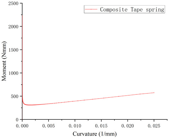
Figure 6.
Relationship between curvature radius and bending moment during the bending process of composite tape spring.
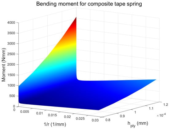
Figure 7.
Relationship between curvature radius and bending moment during the bending process of composite springs with different thicknesses.
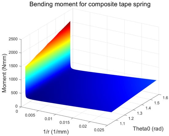
Figure 8.
Relationship between curvature radius and bending moment during bending process of composite material spring with different section central angles.
Table 3.
Mechanical properties of various ply thicknesses of composite tape spring.
Table 4.
Mechanical properties of composite spring with different section central angle.
Combining with previous work [20,22], we compared three types of materials and structures of the spring, as shown in Figure 9. It can be seen that compared with the negative Poisson ratio honeycomb structure spring, the composite material spring has a lower critical bending moment and a higher steady-state bending moment. The unit mass mechanical properties of the three types of materials and structures of the spring are shown in Table 5. It can be seen that in the indicator of critical bending moment, the unit mass critical bending moment performance of the composite material spring is close to that of the ordinary spring, far lower than that of the negative Poisson ratio structure spring. In terms of steady-state bending moment indicators, the composite material spring is better than the ordinary spring and the negative Poisson ratio honeycomb structure spring. Specifically, in terms of critical bending moment, the performance of composite tape spring structures, in terms of unit mass, is improved by 0.2% compared to traditional metal tape spring structures, while the performance improvement is 62.3% compared to negative Poisson ratio honeycomb structure tape spring structures. In terms of steady-state bending moment, the performance of composite tape spring structures, in terms of unit mass, is improved by 162.1% compared to traditional metal tape spring structures, while the performance improvement is 42.9% compared to negative Poisson ratio honeycomb structure tape spring structures. The mechanical performance of different structures has its own advantages. In subsequent research, we will explore the intrinsic mechanical factors that influence bending moments.
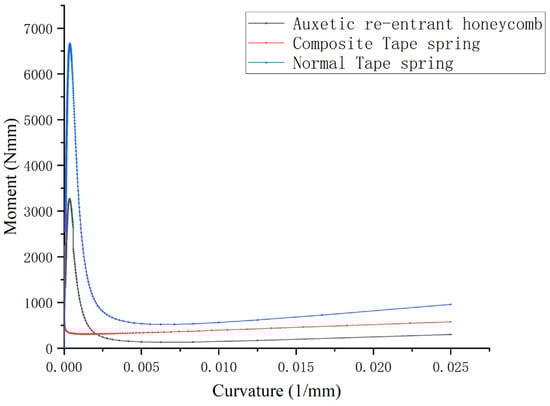
Figure 9.
Different material structure spring mechanical properties comparison.
Table 5.
Different material structure spring mechanical properties comparison.
3. Numerical Analysis
The present study employed a robust methodology to investigate the bending process of a composite material helical spring cylindrical shell using SolidWorks and ABAQUS finite element software. Specifically, a non-linear finite element analysis was carried out by directly importing the SolidWorks model into the ABAQUS software to simulate the bending process of the composite material helical spring cylindrical shell. Furthermore, a reverse bending process simulation was performed by creating a finite element model with shell element S4R5 and employing ABAQUS software. To ensure that the space deployable mechanism model achieves a purely bending state during actual operational processes, MPC constraints were used to establish nodes on both ends of the model, with the centroid of the end face serving as the control node, and coupled them as MPC constraints.
In the ABAQUS finite element software, boundary conditions were applied at the end face’s centroid to simulate the bending moment’s loading effect. The automatic meshing feature of ABAQUS was used with an approximate global size of 0.5 mm and a maximum offset factor of 0.1 for the curvature control. Additionally, the minimum size control was set as a proportion of the global size, with a factor of 0.1. The finite element analysis process employed a large non-linear deformation (NLGEOM) incremental analysis using a solution method based on. Moreover, the automatic stabilization coefficient STABILIZE was set to 0.0002.
The boundary conditions with applied displacement constraints were established as follows: among the six degrees of freedom on one end face of the model, the X-direction displacement, Y- and Z-direction displacements, and rotations were constrained, and an X-direction rotation of 1.57 radians was applied, i.e., an X-direction rotation of 1.57 radians was applied while the other five degrees of freedom were constrained. For the other end section, the X- and Y-direction displacements were constrained, the Y- and Z-direction rotations were constrained, and an X-direction rotation of −1.57 radians was applied. This application ensured that the model bent into a U-shape, which is consistent with the actual working state of the space unfolding mechanism. The parameters used in the analysis are given in Table 1 and Table 2, the boundary conditions are shown in Table 6. And the ply angles are shown in Figure 10. Figure 11 presents the FEM model in detail.
Table 6.
Boundary conditions.
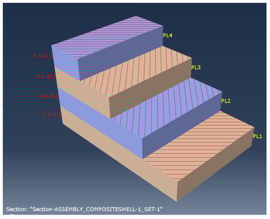
Figure 10.
Laminate ply angle.
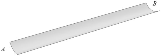
Figure 11.
Finite element model.
Figure 12 shows the stress contour plot of the composite tape spring after folding and bending. The figure shows that the stress distribution is similar to a rectangle, and the middle part of the cylindrical shell becomes flat, which is in line with the variation of cross-sectional curvature in the theoretical model. The maximum stress values for the four layers are 214.0 Mpa, 145.8 Mpa, 153.7 Mpa, and 238.8 Mpa, respectively. The maximum stress value occurs in the fourth layer, and the stress values σ1, σ2, and τ12 in the principal axis direction of the material at the node with the maximum stress value of −255 Mpa, −30.9 Mpa, and −13.6 Mpa are extracted. The material strength parameters are shown in Table 7. Calculations are performed based on the Tsai–Hill failure criteria.
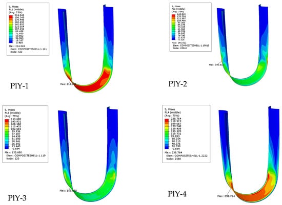
Figure 12.
Stress contour map of composite tape spring laminate ply.
Table 7.
Material strength parameters [23].
The material is within the allowable range.
4. Conclusions
This paper analyzes the mechanical properties of composite laminated tape springs and analyzes and calculates the mechanical characteristics of the folding and bending process of composite laminated open-shell springs. The following conclusions were obtained:
- (1)
- Based on classical laminated plate shell theory, considering the nonlinearity of geometric equations, a nonlinear control equation for the folding and bending of composite laminated tape springs was established, and precise expressions for the folding and bending displacement and bending moment were obtained. The influence of laminate thickness and the central angle of the section on the performance of composite material springs was investigated. It was found that increasing the laminate thickness significantly improves the performance of the composite material spring. Similarly, the performance of the composite material spring shows a linear improvement with an increase in the central angle of the section.
- (2)
- Finite element numerical analysis is carried out on the [−45 45]s laminated composite tape spring, and the correctness of the theoretical derivation is proved by comparing the curvature radius-bending moment change relationship curve.
- (3)
- The mechanical properties of traditional spring structures, negative Poisson ratio honeycomb structures, and composite laminated spring structures are compared with previous work. In terms of critical bending moment, the unit mass critical bending moment performance of the composite laminated tape spring is close to that of the ordinary tape spring and much lower than that of the negative Poisson ratio honeycomb structure tape spring. In terms of steady-state bending moment, the composite laminated spring is better than the ordinary tape spring and the negative Poisson ratio honeycomb structure tape spring.
In the subsequent research, we will delve deeper into the following aspects:
- (1)
- Comparative analysis between composite material springs and negative Poisson ratio honeycomb springs: In further studies, we will conduct an in-depth analysis of the mechanical performance factors that affect the tape spring structure. We aim to identify the key mechanical parameters that influence the mechanical performance of the tape springs and explore more optimal structures. By achieving superior mechanical performance with lighter mass, we aim to contribute to the lightweight design of space-deployable structures.
- (2)
- Composite tape springs are subjected to extreme temperature conditions in practical applications. Therefore, in the subsequent research, it is necessary to consider the influence of the temperature field in the constitutive equations.
Author Contributions
Conceptualization, Y.Y. and F.W.; methodology, Y.Y. and F.W.; software, Y.Y.; validation, Y.Y. and J.L.; writing—original draft preparation, Y.Y.; writing—review and editing, Y.Y., F.W. and J.L.; visualization, Y.Y.; supervision, F.W.; project administration, F.W.; funding acquisition, F.W. All authors have read and agreed to the published version of the manuscript.
Funding
This research was supported by the Key Laboratory of Disaster Forecast and Control in Engineering (Jinan University), MOE of China.
Informed Consent Statement
Not applicable.
Data Availability Statement
The data presented in this study are available on request from the corresponding author.
Conflicts of Interest
The authors declare no conflict of interest.
References
- Seffen, K.; You, Z.; Pellegrino, S. Folding and deployment of curved tape springs. Int. J. Mech. Sci. 2000, 42, 2055–2073. [Google Scholar] [CrossRef]
- Kim, K.-W.; Park, Y. Solar array deployment analysis considering path-dependent behavior of a tape spring hinge. J. Mech. Sci. Technol. 2015, 29, 1921–1929. [Google Scholar] [CrossRef]
- Eigenmann, M.; Schmalbach, M.; Schiller, M.; Schmidt, T.; Scolamiero, L. Ultra-light deployment mechanism (UDM) for sectioned large deployable antenna reflectors. In Proceedings of the 14th European Space Mechanisms & Tribology Symposium—ESMATS 2011, Konstanz, Germany, 28–30 September 2009. [Google Scholar]
- Ye, H.; Zhang, Y.; Yang, Q.; Zhang, B. Quasi-static analysis and multi-objective optimization for tape spring hinge. Struct. Multidiscip. Optim. 2019, 60, 2417–2430. [Google Scholar] [CrossRef]
- Gu, W.; Zhang, J.; Pan, L.; Qu, Y.; Choi, J.-H.; Zhu, X. Coupling Effect of Nonlinear Stiffness of Tape Spring Hinges and Flexible Deformation of Panels during Orbit Maneuvers. Aerospace 2022, 9, 30. [Google Scholar] [CrossRef]
- Footdale, J.N.; Murphey, T.W. Mechanism design and testing of a self-deploying structure using flexible composite tape springs. In Proceedings of the 42nd Aerospace Mechanism Symposium 2014, Baltimore, MD, USA, 14–16 May 2014. [Google Scholar]
- Seffen, K.; Pellegrino, S. Deployment of a Rigid Panel by Tape-Springs; Cambridge University Department of Engineering: Cambridge, UK, 1997. [Google Scholar]
- Seffen, K.A. Analysis of Structures Deployed by Tape-Springs. Ph.D. Thesis, University of Cambridge, Cambridge, UK, 1997. [Google Scholar]
- Seffen, K.; Pellegrino, S. Deployment dynamics of tape springs. Proc. R. Soc. Lond. A 1999, 45, 1003–1048. [Google Scholar] [CrossRef]
- Walker, S.J.; Aglietti, G.S. An investigation of tape spring fold curvature. In Proceedings of the 6th International Conference on Dynamics and Control of Systems and Structures in Space, Liguria, Italy, 18–22 July 2004; Citeseer: Princeton, NJ, USA, 2004. [Google Scholar]
- Chang, W.; Cao, D.; Lian, M. Simulation and analysis of tape spring for deployed space structures. In Proceedings of the Young Scientists Forum 2017, Shanghai, China, 24–26 November 2017. [Google Scholar] [CrossRef]
- Lan, X.; Wang, X.; Lu, H.; Liu, Y.; Leng, J. Shape recovery performances of a deployable hinge fabricated by fiber-reinforced shape-memory polymer. Proc. SPIE 2009, 7289, 728910. [Google Scholar] [CrossRef]
- Oberst, S.; Tuttle, S.; Griffin, D.; Lambert, A.; Boyce, R. Experimental validation of tape springs to be used as thin-walled space structures. J. Sound Vib. 2018, 419, 558–570. [Google Scholar] [CrossRef]
- Yang, H.; Liu, R.; Wang, Y.; Deng, Z.; Guo, H. Experiment and multiobjective optimization design of tape-spring hinges. Struct. Multidiscip. Optim. 2015, 51, 1373–1384. [Google Scholar] [CrossRef]
- Wang, B.; Seffen, K.A.; Guest, S.D. Folded strains of a bistable composite tape-spring. Int. J. Solids Struct. 2021, 233, 111221. [Google Scholar] [CrossRef]
- Elsheikh, A. Bistable morphing composites for energy-harvesting applications. Polymers 2022, 14, 1893. [Google Scholar] [CrossRef] [PubMed]
- Kajihara, S.; Yokozeki, T.; Aoki, T. Dimension effects on the stowability and self-deployment behavior of CFRP bistable open-section semi-cylindrical beam. Compos. Struct. 2023, 307, 116628. [Google Scholar] [CrossRef]
- Yang, H.; Lu, F.; Guo, H.; Liu, R. Design of a new N-shape composite ultra-thin deployable boom in the post-buckling range using response surface method and optimization. IEEE Access 2019, 7, 129659–129665. [Google Scholar] [CrossRef]
- Yao, Y.; Li, G.; Ning, X. Ultra-thin, Ultra-lightweight Structural Electronic Skin for Measurements of Tape-spring Hinge Behavior. In Proceedings of the AIAA Scitech 2021 Forum, Virtual Event, 11–21 January 2021. [Google Scholar] [CrossRef]
- Yang, Y.; Wang, F.; Liu, J. Application of Honeycomb Structures in Key Components of Space Deployable Structures. Adv. Mater. Sci. Eng. 2022, 2022, 4756272. [Google Scholar] [CrossRef]
- Yee, J.; Soykasap, O.; Pellegrino, S. Carbon fibre reinforced plastic tape springs. In Proceedings of the 45th AIAA/ASME/ASCE/AHS/ASC Structures, Structural Dynamics & Materials Conference, Palm Springs, CA, USA, 19–22 April 2004. [Google Scholar] [CrossRef]
- Yang, Y.; Wang, F.; Liu, J. The Exact Solution of the Bending Moment in the Folding Process of Negative Poisson’s Ratio Honeycomb Tape Spring and Multi-Objective Optimization Design. Aerospace 2023, 10, 390. [Google Scholar] [CrossRef]
- Olsson, R.; André, A.; Hellstrm, P. Analytical modelling and FE simulation of impact response and damage growth in a thin-ply laminate. In Proceedings of the 20th International Conference on Composite Materials, Copenhagen, Denmark, 19–24 July 2015. [Google Scholar]


Disclaimer/Publisher’s Note: The statements, opinions and data contained in all publications are solely those of the individual author(s) and contributor(s) and not of MDPI and/or the editor(s). MDPI and/or the editor(s) disclaim responsibility for any injury to people or property resulting from any ideas, methods, instructions or products referred to in the content. |
© 2023 by the authors. Licensee MDPI, Basel, Switzerland. This article is an open access article distributed under the terms and conditions of the Creative Commons Attribution (CC BY) license (https://creativecommons.org/licenses/by/4.0/).