Article

Impacts of Micro-Deviations of Aperture on the Characteristics of Collision Atomization Field

1
Centre of Ultra-Precision Optoelectronic Instrument Engineering, Harbin Institute of Technology, Harbin 150080, China
2
Key Lab of Ultra-Precision Intelligent Instrumentation, Harbin Institute of Technology, Ministry of Industry and Information Technology, Harbin 150080, China
*
Author to whom correspondence should be addressed.
Appl. Sci. 2022, 12(9), 4685; https://doi.org/10.3390/app12094685
Submission received: 22 February 2022 / Revised: 26 April 2022 / Accepted: 5 May 2022 / Published: 6 May 2022

Abstract

:
As the final flow channel of the liquid rocket engine, the manufacturing of impinging atomization nozzles has become a critical link in the manufacture of impinging atomization components. At present, the high-precision machining of millimeter nozzles in large-scale production is quite difficult, which inevitably leads to the diversity of internal flow field and atomization field parameters. In this investigation, the influence of the diameter deviation of impinging nozzles on the atomization field is analyzed by experiment. The transparent nozzle is installed in a typical colliding atomizer. The ultra-precision measurement is carried out by the optical fiber measurement system and the flow field in the nozzle is visualized. The information of atomized droplets in the atomization field is assembled by the laser interferometric particle imaging technology (IPI). The experimental results indicate that the micro-deviations of the collision aperture have a profound influence on the cavitation state of the flow field in the nozzles and the atomization characteristics (droplet diameter and atomization cone angle) of the atomization field.

1. Introduction

The impinging nozzle, which applies kinetic energy to break the propellant jet, has the characteristics of brisk response, expeditious mixing and combustion, is universally employed in liquid rocket engines. Manufacturing practice establishes that the particle diameter and distribution of atomized droplets influence combustion and efficiency of liquid rocket engines significantly [1]. With the speedy advancement of high-precision machining and measurement technology, the diameter of the nozzle in a liquid rocket engine can be manufactured to hundreds or even tens of millimeters to the atomization performance. Many scholars have researched high-precision measurement approaches for micropores with large aspect ratio, which can earn high-precision measurement data of the internal geometry structure of an orifice, to upgrade the enhancement of micropore processing technology [2,3,4,5,6]. These consequences are also constructive to fathom and inspect the atomization excellence of the fuel atomization field involved by the relative position and geometry of nozzles comprehensively. The accuracy of the freshest measurement technology can attain nanometer level at a high aspect ratio [4,5,6]. Therefore, it is expedient to calibrate the orifice to glean more comprehensive data, which can confirm the consistency of the internal diameter of the orifice and ensure the disclosure of the individual microscopic deviation induced by machining deviation.
The existing methods of manufacturing are challenging to produce ideal smooth orifices, which thoroughly conform to the expected ones, especially in volume production, due to the limitations of the manufacturing mechanisms and technical level, such as insufficient strength and rigidity of carving apparatuses. For bounteous pairs of orifices of the liquid rocket engine, the internal diameter of the nozzle directly affects the exit velocity of two jets [7]. According to extensive nozzle appraisal data, the machining deviation generally fluctuates within the range of 15% of the ideal value, which is diversified, such as the diameter of the impinging orifices, inclination angle and relative position, etc. However, in factual construction, more than one type of deviation will exist in the impinging nozzles, making it imperative to inspect heterogeneous deviation to explore the influence of specific deviation on the internal flow field and atomization characteristics. In addition, the influence of nozzle structure deviation on atomization characteristics must be considered when designing nozzle manufacturing tolerance and controlling machining error. The most influential structural deviation should be strictly controlled to ensure the atomization characteristics and appropriately tolerate microstructural deviation to enhance the construction efficiency and decrease the manufacturing costs.
In double jet impingement atomization, two impinging jets are ejected from two nozzles, respectively, and then collide at a certain collision angle, forming an oval liquid membrane perpendicular to the plane of the two jets, whose boundary is closed at low velocity [8]. Under the condition of high-speed impact, the liquid membrane is disturbed by the surrounding air flow, and vibration waves will be generated on the surface [9]. When the amplitude of the vibration wave reaches a certain value, the liquid membrane will break, resulting in fracture zone and liquid filament, which belongs to the primary stage of atomization. When moving with the surrounding air relatively, the fracture zone and the liquid filament extend to break up, developing atomization droplets, which belongs to secondary atomization. When the fracture zone appears in the liquid membrane rupture, the fracture occurs at the two adjacent peaks of the liquid membrane vibration wave. Therefore, the width of the fracture zone is approximately half the wavelength of the liquid membrane rupture [10]. Due to the effect of liquid surface tension, the fracture zone will gradually converge to form a liquid filament, which will break and produce large droplets. Under the synthetical influence of surface tension, density, viscous force and ambient air flow, large droplets proceed to break. When the droplet adapts itself to dynamic equilibrium with the surrounding airflow field, the eventual atomized droplet is generated [11].
Since the jet impingement atomizer has the advantages of uncomplicated structure, marvelous atomization and mixing performance, researchers have carried out extensive and in-depth research since Savart observed two identical coaxial jets in 1833, and the liquid membrane generated by the collision broke into droplets [12]. Droplet size, atomization angle and flow coefficient are the most prominent parameters that an abundant amount of researchers are interested in. Based on the current research, the effects of liquid membrane breakage characteristics, atomization droplet formation process, spray conditions and nozzle structural parameters on the spray characteristics of impinging nozzles have been investigate extensively [13,14,15,16,17]. Chen et al. [11] and Zheng et al. [18] employed numerical simulation to capture the liquid membrane formed after impact and inspect the impingement atomization growth of two jets, summarizing that the rupture process of the liquid membrane is mainly affected by liquid viscosity and surface tension. Salvador et al. [19] have inquired the atomization process of incompressible multiphase flow of diesel under low pressure injection by adaptive octree grid and VOF which involves a complex physical process and gas–liquid interaction. Lee et al. [20] studied the breakup and atomization process of two impinging jets with non-Newtonian fluid as working fluid and found that with the increase in jet pressure, the shape of the liquid membrane formed after the impact of the gel propellant simulation material is transformed from the edge closed state to the edge opening state. Yang et al. [21] and Baek et al. [22] studied the atomization characteristics of different working fluids and found that the development process of spray can be divided into four parts: the complete conical liquid membrane stage, the liquid membrane and liquid zone coexistence stage, the turbulent reticulated liquid zone stage and the liquid zone and droplet coexistence stage, and the size of the liquid membrane increases with the increase in the jet velocity when the working mediums are water and the gel material. Ren et al. [23] mainly researched the effects of nozzle geometry and Weber number on the characteristics of liquid membrane and droplet. The decisions demonstrate that the breakup mode of the liquid membrane is determined by Weber number and nozzle length. The increase in the Weber number promotes the breakup of liquid tape into liquid filaments and droplets. Ma et al. [24] studied the effects of impingement parameters, geometry parameters and fluid viscosity on atomization performance and found that with the increase in injection pressure, the velocity of the droplet increases in all directions, the SMD (Sauter Mean Diameter) of the droplet decreases and the dimensionless average size SMD/D (D is Droplet diameter) of the droplet tends to be a constant value of 0.14. Nowadays, the research has gradually been enriched by simulation and experiment; however, there still exists indispensable research that requires enriching.
From the brief review, it indicates that the diversity of the nozzle structure parameters, injection conditions and collision angle which may affect the atomization performance of the colliding atomizer has been investigated. Nonetheless, owing to the complexity of fluid dynamics, the miniaturization of nozzles and the lack of high-precision measurement and processing approaches, the analysis of the influence of machining errors on the atomization field is still in the primary stage. The existing attempts mostly assume the apertures as fixed, the micro-deviation of the nozzle structure created by machining error or abrasion in the machining process is therefore entirely neglected.. As one of the minor deviations caused by machining errors, the diameter deviation of orifice seriously affects the quality of collisional atomization. Moreover, there are few available perspective holes to show the flow field in the impact atomizer in the current research. It is necessary to develop a visual orifice so that we can better obtain the real-time state of the internal flow field.
In this paper, the influence of the small deviation of pore size on hydraulic parameters and atomization characteristics, and the sensitivity of atomization field to its response are studied in a targeted manner. A transparent nozzle was applied to visualize the internal flow field to study the effect of cavitation phenomena on the atomization field parameters. The nozzle diameter is ultra-precisely measured by the self-developed optical fiber probe based on orthogonal micro-focus alignment to ensure the accuracy of the nozzle diameter. In this paper, by building a collision atomization and laser interference particle measurement device, the flow coefficient, droplet diameter and atomization cone angle were measured, and the influence of the nozzle hole processing deviation on the above parameters was clarified.

2. Theoretical Background

Cavitation indicates the phenomenon of violent vaporization on the liquid surface and inside by curtailing the local liquid pressure to lower than the saturated vapor pressure under constant temperature [25,26,27,28]. With the increase in internal and external pressure distinction and flow velocity, the cavitation flow field in the orifice will present four contrasting states, as shown in Figure 1. When the pressure reaches the critical value of cavitation, bubbles emerge at the inlet of the nozzle, generating the initial stage of cavitation (Cavitation inception, see Figure 1a). When the injection pressure increases, the cavitation domain in the nozzle progressively extends to the nozzle outlet (Cavitation growth, see Figure 1b), until it expands to the orifice outlet and forms super-cavitation (Super cavitation, see Figure 1c). When the pressure increases further, the flow field in the orifice will develop into an advanced state (Hydraulic flip, see Figure 1d). Under the condition of flip flow, the vapor outside the nozzle will pour back into the nozzle, occupying the original cavitation area, with the severe bubble phenomenon disappearing. Instead, a slim membrane of vapor adheres to the inwall of the nozzle separating the liquid, which decreases the passage area in the orifice, and enormously diminishes the flow coefficient (the mass flow rate of the fluid flowing through the orifice in unit time and under constant pressure). A more considerable flow coefficient initiates a narrower pressure loss when the fluid flows through the nozzle, which reflects the nozzle performance more critically.
The state of cavitation effect determines that of the jet, therefore encountering the critical pressure of cavitation effect and evaluating the state of cavitation effect for the stability and atomization characteristics of direct injection nozzle appear extremely significant. There are two considerable demarcation points for the reversal of cavitation effect state: cavitation inception and hydraulic flip. The critical pressure of these two stages divides the jet into stable and unstable states. When the jet pressure is less than the initial critical pressure of cavitation, there is no cavitation in the orifice with a stable jet. The cavitating flow will conversely develop into a jet which represents instability.
The parameters characterizing the cavitation effect in the orifice are cavitation coefficient K and discharge coefficient Cd, which are expressed as
K = P i n P v P i n P o u t ( P i n P o u t )
C d = m ˙ A 2 ρ l ( P i n P o u t ) ( P i n P o u t )
where Pin, Pout and Pv are the injection pressure, ambient pressure and saturated vapor pressure, respectively (KPa). Moreover, m ˙ is the mass flow (g/s) and A is the cross-sectional area of the orifice (cm2).
The cavitation coefficient reflects the relationship between the internal and external pressure distinction and the saturated vapor pressure and determines the length of the cavitation area. The narrower the cavitation coefficient, the more conducive to cavitation. The bubbles generated by cavitation will occupy the internal capacity of the orifice and narrow the flow channel, affecting the discharge coefficient, which signifies the mass flow of fluid medium through the orifice in a unit time and under constant pressure. The increase in the flow coefficient provokes the decrease in pressure loss when fluid flows through the nozzle, which reveals the performance of the nozzle effectively.

3. Principle and Methods

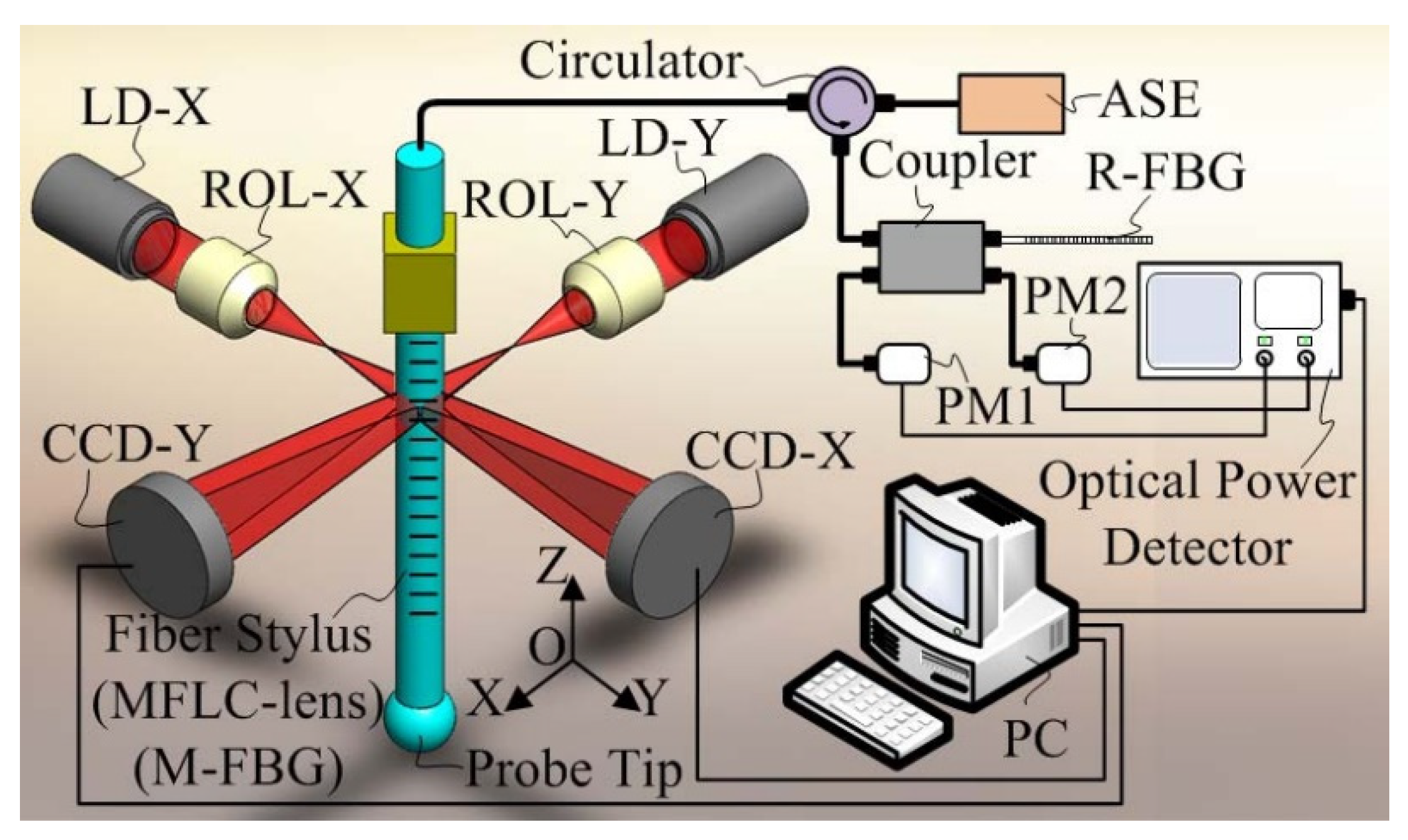
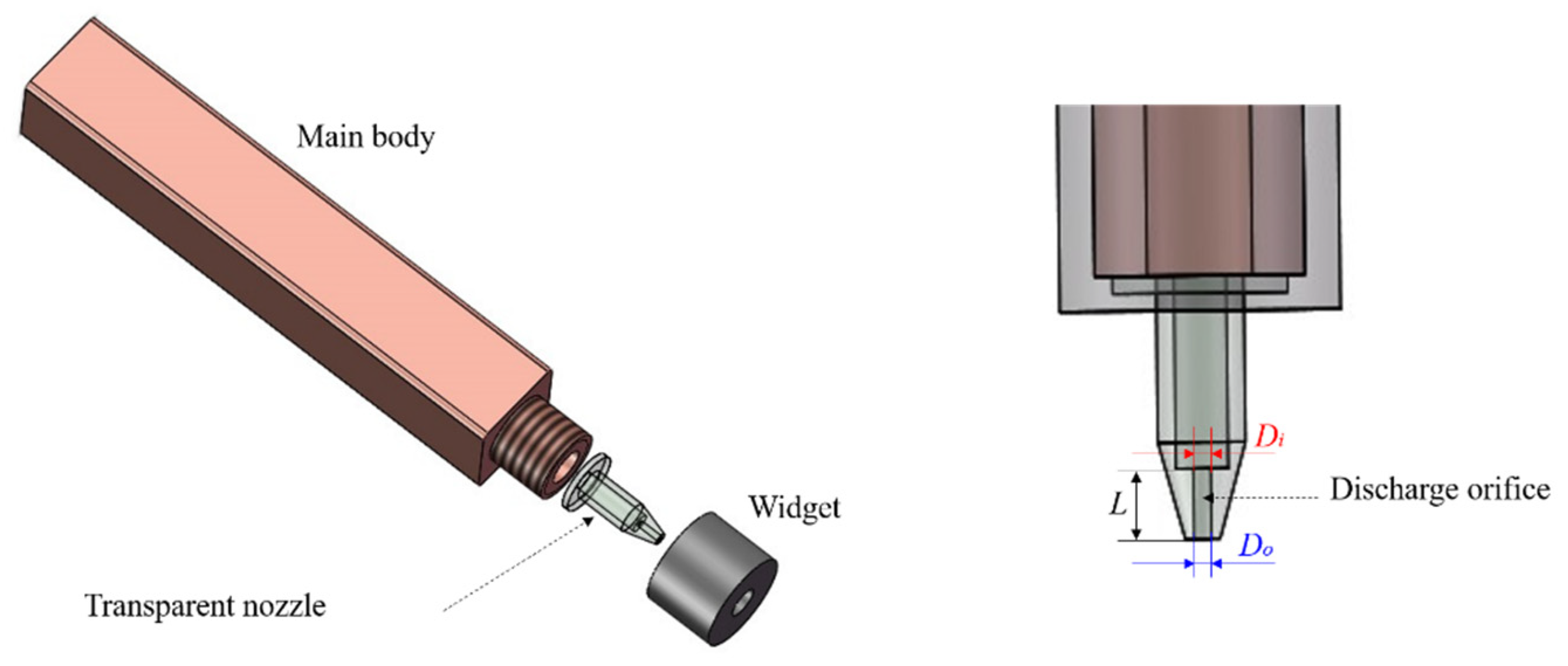
3.1. Measurement Method of Nozzle Diameter

To enhance measurement precision, the nozzle evaluation adopted in this investigation is an ultra-high-precision three-dimensional micro-displacement measurement system independently developed by an optical fiber probe based on orthogonal optical fiber collimation, which is made of FBG (fiber Bragg grating). The radial deflection or axial buckling deformation of the fiber probe is induced by the force of the fiber probe. The deformation displacement of the fiber rod at the detection point is measured by the optical fiber collimation optical path. The fiber probe converts the three-dimensional micro-displacement of the fiber probe into the centroid displacement of the collimating image, which can realize high-precision three-dimensional micro-displacement measurement.
The principal diagram of the optical fiber probe and measurement system based on orthogonal optical fiber collimation is shown in Figure 2 [5]. The optical fiber probe consists of an optical fiber rod and a spherical tip. The optical fiber rod is used as a MFLC-lens (micro focal-length cylindrical lens). The arrangement of two mutually orthogonal optical fiber collimating paths is identical, which are distributed along X and Y directions, respectively. The beam emitted by the laser diode (LD/Laser-X, LD/Laser-Y) through the reflective objective lens (ROL) converges into a point light source on the front focal plane of the cylindrical lens through the long working distance objective lens (Objective-X, Objective-Y). The beam emitted by the point light source is collimated through the cylindrical lens, and its collimating image is detected by the linear array charge-coupled devices (CCD-X, CCD-Y). The deformation and displacement of the optical fiber measuring rod are measured at the detection point OP by the orthogonal optical fiber collimating optical path. The optical power meters (PM1 and PM2) receive the power spectrum.
The experimental device of the optical fiber probe based on orthogonal fiber collimation is exhibited in Figure 3. The length of the optical fiber probe is 15 mm, the diameter of the optical fiber rod (single-mode optical fiber without coating) is 125 μm and the focal length is 93 μm. The tip diameter is 131.52 μm, the working distance of the long working distance objective is 20 mm, the resolution of the linear array camera is 2048 pixel × 1 pixel and the pixel size is 10 µm/pixel. The imaging distance between the detection surface of the linear array camera and the optical fiber probe is 125 mm, and the detection point is OP, whose height is about 6 mm.
The system is allocated with a visual system to monitor the fiber probe in real time. The experimental instrument is established in a glass enclosure to decrease the influence of air flow and installed on the active vibration isolation platform to curtail the effect of vibration interference. Driven by the three-dimensional nanopositioning platform, the plane mirror engages with the tip of the optical fiber probe.
The three-dimensional detection organization can accomplish 5 nm radial resolution and 8 nm axial resolution. The expanded uncertainty of optical fiber probe based on orthogonal optical fiber collimation is 0.21 μm for k = 2 (k is coverage factor). There are more adequate descriptions of the optical fiber probe measurement arrangement in Refs. [5,29,30]. Recently, an advanced three-dimensional isotropy microprobe for the assessment of microstructures to estimate the diameter was proposed by Li et al. [31] to provide higher efficiency and accuracy of the appraisal. The measurement data of employed nozzles experimentally are detailed in Table 1.

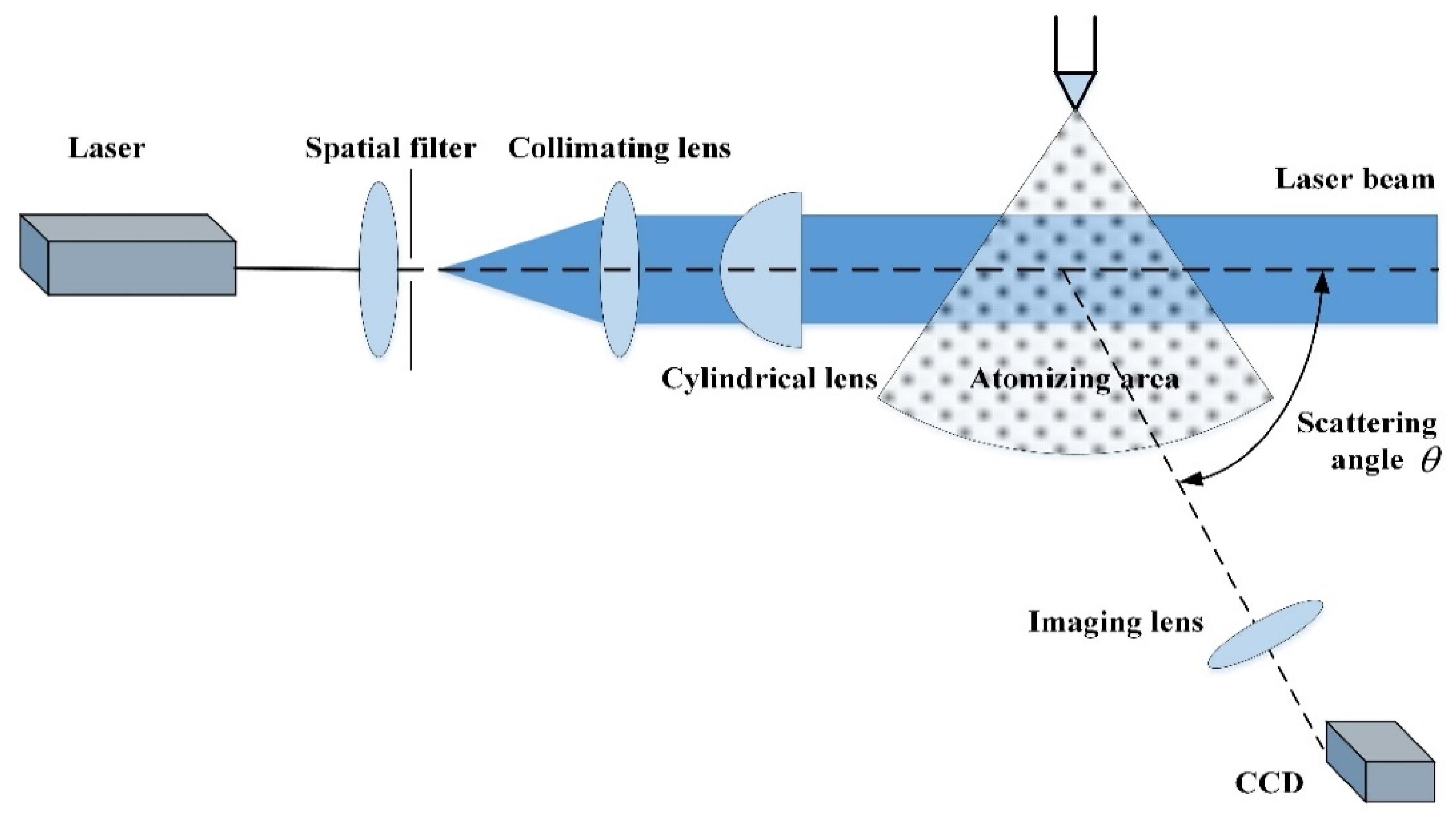
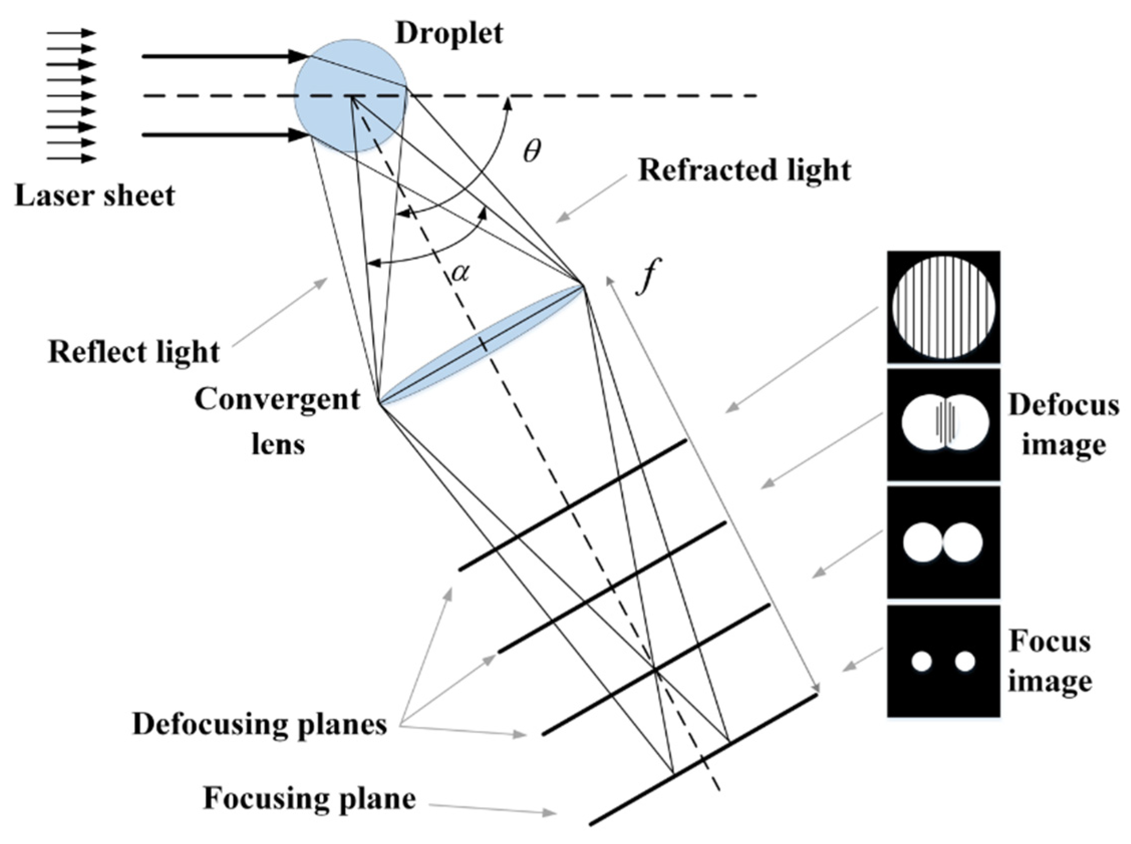
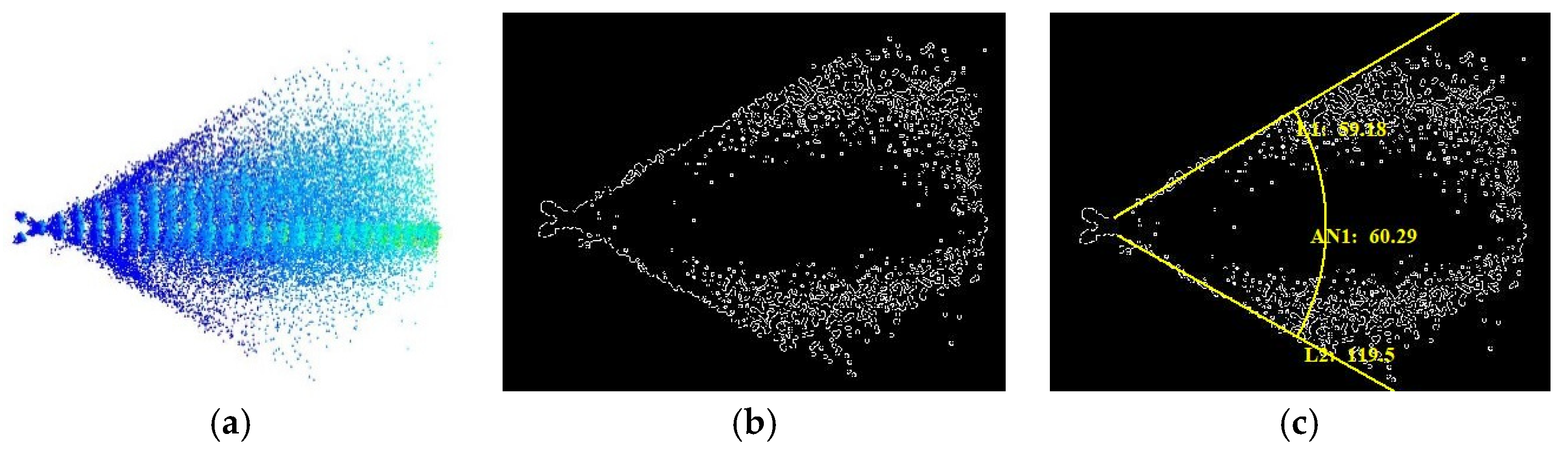
3.2. The Extraction Method of Atomized Particle Information

Droplet diameter is estimated by laser interferometric particle imaging technology [7,32,33,34], which was initially proposed by Knig et al. [32] in 1986 based on the scattered light distribution of particles. The relationship between light intensity distribution and particle diameter is accessed by Mie scattering theory. A focused laser beam is experimented to irradiate the particle field, and a one-dimensional light intensity detector is employed to receive the scattered light in the forward scattering region of the particle. Instantaneous particle size distribution is achieved, which convinces that this arrangement incarnates ultra-precision. IPI technology has become a hot topic in particle field measurement because of its non-contact and high-precision characteristics. It is also suitable for collision atomization particle field.
Figure 4 is the IPI measurement optical path for colliding particle field. The specific measurement process is as follows: the laser emits a thin beam, which is expanded, filtered and collimated, compressed into a sheet by a cylindrical lens and irradiates the particle field to be measured. Scattered light imaging of the single droplet is shown in Figure 5. When the spherical particles are irradiated by laser beam, the focused images of reflected light and refracted light are generated on the focusing image plane of particles, and the interference fringe pattern is formed on the defocusing image plane of particles. The diameter information of particles can be obtained by analyzing two-point image or interference particle fringe pattern. Based on the phase difference method, the formula of droplet size is deduced as follows
d p = 2 λ n 1 f ( cos θ 2 + n sin θ 2 1 + n 2 2 n cos θ 2 ) 1
where f is the ratio of α (the collection angle) to N (the number of interference fringes), which means the frequency of interference fringes, λ is the wavelength of the laser (nm), n is the relative refractive index, n1 is the air refractive index and θ is the scattering angle (°).
The measurement of the atomization cone angle is completed by image shooting and post-processing of atomization field. Through image processing and experimental shooting, the collision atomization image is obtained, and the specific software is used for programming to realize the filtering and denoising (mean filter), binarization and morphological edge extraction of the original image, so as to obtain the outer contour of the atomization field. The atomization cone angle can be obtained by importing the processing image into the IPP6.0 software and automatic recognition processing. Taking an atomization simulation result as an example, the original, process and result images of the atomization cone angle detection are shown in Figure 6a–c, respectively.

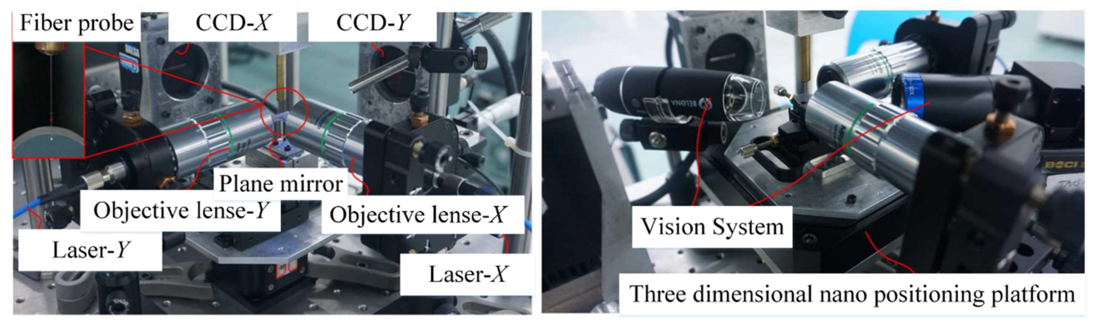
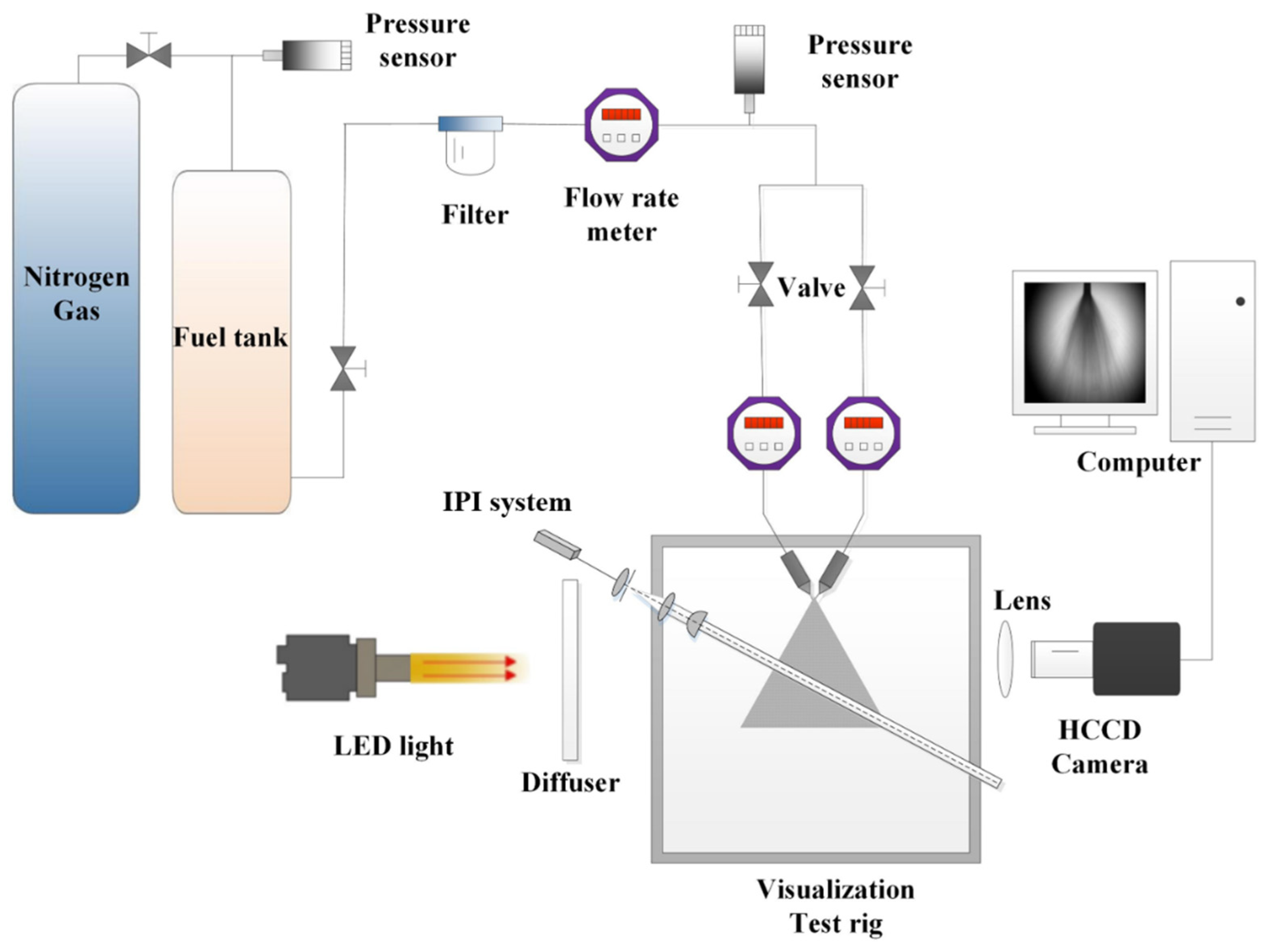
4. Experimental Setup

The experimental system for the internal flow field of the impinging nozzle is shown in Figure 7. The nitrogen bottle outputs high-pressure nitrogen to the sealed water tank, and the injection pressure of 0~1.0 MPa can be provided by adjusting the pressure reducing valve. Before entering the tributary, a flow sensor and a pressure sensor detect the total flow value and injection pressure value in real time. After entering the tributary, before reaching the nozzle, a flow sensor and a filter were installed to detect the branch flow and purify water quality. The measurement accuracy of flow and pressure sensors were ±0.5% (1.5~100 L/h) and 0.25% (0~1.0 MPa) of full scale, respectively. The image acquisition system is provided with stable background light by 15 W white LED light source and diffusion plate. The high-speed CCD camera of MotionBLITZ EoSens Cube7 combined with a large depth of field continuous zoom microscope lens which can be adjusted manually can be used to acquire high-quality images of flow field and atomization field in the orifice. The system is also applied to the measurement of the atomization cone angle, as shown in Figure 6.
For the purpose of this paper, an atomizer with a replaceable orifice is designed. The collision structure consists of two identical atomizers. Since the diameters of the two jets are relatively small, in order to realize the two jets can collide together or adjust the collision angle, the azimuth adjustment system needs to be able to accurately adjust the direction of the two jets. Therefore, the two atomizers are, respectively, installed on two 360° rotating cloud disks with different adjustable angles. The collision angle of the two jet orifices is adjusted by the cloud disk. The adjustment range is between 0° and 180° without directly adjusting the positions of the two atomizers. The structure of a single injector is shown in Figure 8. It consists of three parts: body, replaceable transparent orifice and a small part. The main body is symmetrically mounted on the rotating cloud disk. Transparent orifice is processed by poly (methyl methacrylate) to visualize the flow field inside the orifice. The small part is to install the orifice on the main body through the internal thread to achieve the purpose of fixing the orifice. The flow orifice and its upstream flow channel are exposed, so that the internal flow field can be observed clearly.

5. Results and Discussion

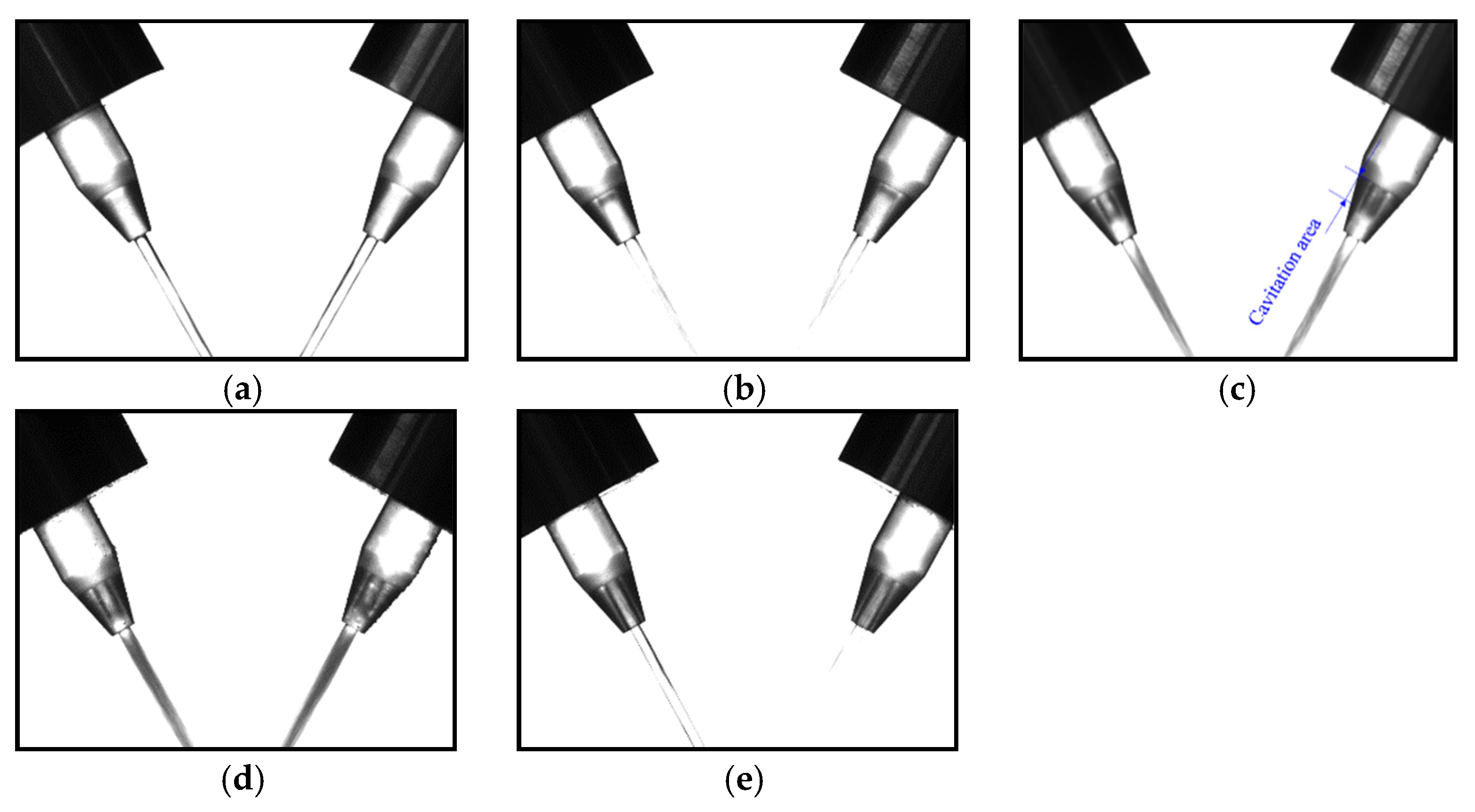
5.1. Cavitation Experiment of Internal Flow Field

Previous investigations on the influence of nozzle diameter are usually carried out at the same time as the research on the influence of the nozzle aspect ratio, and it is concluded that it is more difficult for the initiation and development of cavitation at a higher aspect ratio. To the best of our knowledge, a separate study on the influence of diameter and its sensitivity level has not been reported, especially for the colliding orifices. In this paper, eleven pairs of nozzles with design diameters varying in the range of 0.95 mm~1.00 mm~1.05 mm are used to study the influence of small diameter differences, and the measurement data are detailed in Table 1.
Firstly, the cavitation phenomenon of the internal flow field is simulated. According to the simulation results, the range of injection pressure in the experiment is set as 0.2 MPa ~ 0.8 MPa. In this range, the internal flow field will appear in four states: initial cavitation, cavitation development, supercavitation and jet. Figure 9 shows the cavitation state of the flow field in the 1 mm orifice when the aspect ratio is 4 in the experiment. The experimental phenomena of the flow field in other apertures can be seen from Ref. [35]. It can be seen from Figure 9a that when the jet pressure is 0.2 MPa, there is no cavitation phenomenon in the orifice, the two jets are very soft and the collision is not intense. When the pressure reaches 0.3 MPa [see Figure 9b], cavitation begins to appear in the orifice and the collision between the two jets becomes intense. With the increase in pressure [see Figure 9c], the cavitation area in the orifice becomes larger and the jet collision becomes more intense. Until the pressure is 0.4 MPa [see Figure 9d], the cavitation area in the orifice almost reaches the maximum, which is very close to the supercavitation state and almost reaches the most intense collision state. When the pressure increases to 0.8 MPa [see Figure 9e], the internal flow field has reached the state of jet flip, and the two jets return to a relatively stable state again. The experimental results are consistent with the simulation results detailed in Ref. [36].
According to the cavitation experimental results, the increase in the nozzle diameter leads to the gradual increase in the critical pressure at the beginning of cavitation, and the pressure required for super-cavitation and hydraulic turnover will be higher. On the contrary, the nozzle with smaller aperture has more chance to reduce cavitation, which is due to the changes in pressure and velocity. When other factors remain unchanged, the smaller the diameter, the higher the fluid velocity and the lower the local pressure at the orifice inlet; therefore, the easier it is to reduce to the saturated vapor pressure, thereby promoting cavitation.

5.2. Influence of Colliding Aperture Deviation on Atomization Effect

Figure 10 shows the atomization field structure of three equal diameter nozzles (the diameter of each pair of colliding nozzles remains equal) N1, N6 and N11 at the collision angle of 60° under different input pressures. It can be found that no matter what kind of inner diameter of the nozzle, when the injection pressure increases, accompanied by the breakup of the liquid membrane, the collision between the two jets will become more intense. When the pressure reaches a certain value, the atomization field will almost maintain a steady state, and the parameters of the atomization field will tend to be stable. When the jet pressure is small, the liquid membrane has a relatively complete and regular edge, and the size of the liquid membrane increases with the Weber number. For N1, N6 and N11, when the injection pressure is 0.30 MPa, 0.35 MPa and 0.32 MPa, respectively, the edge of the corresponding liquid membrane begins to break, becoming no longer continuous and regular, and obvious surface waves appear on the surface of the liquid membrane. This is because the liquid membrane is disturbed by the external air at the gas–liquid interface and forms waves on its surface, which is also called air disturbance wave. The bottom liquid membrane appears to peel and then gradually breaks up to form droplets.
From the change in the atomization field shown in Figure 10, we can see that with the increase in injection pressure, the liquid membrane formed at the bottom of the liquid membrane shrinks and the spray angle continues to increase. In Figure 10a–c, when the jet pressure reaches 0.84 MPa, 0.87 MPa and 0.85 MPa, respectively, it is difficult to see the edge of the liquid membrane formed by jet collision, which is called boundless mode. With the increase in the Weber number, the position of the liquid membrane breaking is closer to the impact point of the jet, which indicates that the air disturbance wave increases with the increase in the Weber number. In the boundless mode, during the downward movement of the periodic bow-shaped liquid filament, a large number of droplets appear due to continuous breaking.
The diameter directly affects the orifice flow, while the injection pressure controls the growth rate and trend of volume flow. Figure 11 shows the relationship between volume flow rate and injection pressure in single nozzles with small deviation. Taking N6 (1.00 mm) as the standard diameter, the critical pressure required to induce cavitation and hydraulic turnover will be reduced by approximately 2.1% and 2% when the diameter is reduced by 2%, and will be further reduced to 5.3% and 6.3% when the diameter is reduced by 4%. Similarly, when the diameter increases by 2%, the critical values of the initial cavitation and hydraulic turnover increase by approximately 2.6% and 2.5%, and when the diameter increases by 4%, the critical values will further increase to 4.7% and 5%.
In addition, it can be seen from Figure 11 that for a nozzle with a specific diameter, the volume flow rate increases with the increase in injection pressure. However, when cavitation occurs, the flow channel narrows and the volume flow rate decreases sharply until the hydraulic overturning phenomenon is completed, and the volume flow rate begins to increase again, but the growth rate slows down. In the 4% deviation orifice with a diameter of 1 mm as the standard, from the initial pressure of 0.2 MPa to the hydraulic turnover, the volume flow rate increases by nearly 30 L/h at most and 21.7 L/h at least. When the injection pressure increases to 0.8 MPa after hydraulic turnover, the volume flow rate generally increases by only approximately 20 L/h. Figure 11 also shows that for the orifice with diameter deviation, the larger the aperture is, the greater the flow of the nozzle is. The nozzle with negative deviation (0.95–1.00 mm) is easier to reach the state of hydraulic turnover than the nozzle with positive deviation, which also illustrates that the smaller aperture nozzles can bear less pressure.
The relationship between the discharge coefficient Cd and cavitation number K of single side small deviation cylindrical nozzles is depicted in Figure 12. The variation characteristics of Cd show a great difference with the increase in K before and after hydraulic turnover. Before the hydraulic turnover, for a specific orifice, when the injection pressure gradually increases, the influence of the viscous resistance on the liquid movement in the orifice inner wall will decrease, which leads to the monotonic increase in Cd with the decrease in K. When hydraulic overturning occurs, due to the generation and development of cavitation, the flow in the orifice decreases rapidly, resulting in a significant reduction in the discharge coefficient. After hydraulic turnover, because a layer of gas membrane is attached to the inner wall of the nozzle, the viscous resistance is greatly reduced and the flow coefficient increases again. For the nozzle with diameter deviation, the larger the forward deviation, the lower the Cd corresponding to the nozzle, which is directly related to the outlet area of the nozzle, and the larger the area, the lower the flow rate.
It can also be seen from the curves of multiple orifices that the inflection point of each curve changes regularly. The smaller the nozzle, the larger the corresponding inflection point. The inflection point of each curve is the critical point for the emergence and end of hydraulic pressure. This also implies that a small orifice requires less injection pressure, and vice versa. It can be concluded from Figure 12 that the increase in the orifice diameter (positive deviation) reduces the flow coefficient and the curve inflection point gradually moves to the left and down, making cavitation and hydraulic overturning more difficult to occur. On the contrary, the decrease in the orifice diameter (negative deviation) increases the flow coefficient, and cavitation and hydraulic turnover will occur earlier with the increase in injection pressure.
Figure 13 is the SMD curve of different injection pressures and small range of impact nozzle diameter change. Among them, Figure 13a shows the relationship between SMD and collision aperture under different injection pressures. Figure 13b is the curve of SMD with injection pressure for collision aperture with 5% deviation based on 1.00 mm.
It is obvious from Figure 13a that SMD increases with the increase in the diameter of the impinging nozzle. Under the same injection pressure, the increase in the nozzle diameter leads to the weakening of the cavitation in the internal flow field, the softer collision between the two jets, the insufficient atomization in the atomization field and the larger SMD. When the diameter of impinging nozzle varies in the range of 0.95–1.05 mm, the variation range of SMD becomes smaller and smaller with the increase in injection pressure. In addition, for a fixed orifice diameter, SMD tends to decrease with the increase in injection pressure, and the decreasing range gradually becomes smaller, and finally tends to a stable SMD value. For collision nozzle N1, the maximum difference of SMD corresponding to four injection pressures is 5 μm, while the difference is about 25 μm when colliding with nozzle N11.
In Figure 13b, SMD decreases with the increase in injection pressure. This is because the increase in injection pressure will lead to more obvious cavitation phenomenon in the internal flow field, which directly causes the increase in collision velocity. The impact strength of the two jets is greater, the atomization field is more fully atomized and the SMD is smaller. When the injection pressure is in the range of 0.20–1.00 MPa, the SMD range of N10 jet with colliding aperture is the largest, which is 22 μm, and the SMD range of N2 jet with colliding aperture is the smallest, which is 8 μm. When the diameter of the impinging nozzle changes uniformly about 1 mm, the SMD changes relatively evenly, and with the increase in injection pressure, it will eventually become a stable value. In a word, it can be seen from Figure 13 that the increase in the injection pressure and the decrease in the impinging orifice diameter will lead to higher jet velocity and smaller jet diameter, which will make the impact of the atomization field more intense, the atomization effect more sufficient and obtain smaller SMD.
Figure 14 shows the variation curve of the atomization cone angle with colliding aperture and jet pressure. It can be seen from the figure that with the increase in injection pressure, the atomization cone angle corresponding to the same pair of nozzles increases, and the final atomization cone angle tends to be stable, and gradually approaches and does not exceed the collision angle of the two nozzles. When the injection pressure is 0.3 MPa, the difference in the atomization cone angle of five pairs of nozzles is the smallest, and then the difference increases gradually until the atomization field reaches the steady state. When the pressure is small, the atomization cone angle increases greatly. This is due to the sudden appearance of cavitation, which causes the jet to collide violently. At the same injection pressure, the atomization cone angle increases with the increase in the nozzle diameter. The atomization cone angle of N2 and N10 approaches 53° and 60°, respectively. This is because the process of the liquid membrane breaking is disturbed by the surrounding air. When the inner diameter of the nozzle is small, the liquid membrane formed by the collision of two jets is relatively thin. At the same time, the research of Heidmann [37] shows that the inner diameter of the nozzle has a weak influence on the waviness of the liquid membrane surface, and the waviness of the liquid membrane formed by the small inner diameter of the nozzle is denser. A slight disturbance can rupture the formed liquid membrane, and it is not easy to spread to both sides, so the final spray angle is small.

6. Conclusions

The influence of the small geometric deviation of impinging nozzle caused by machining error on internal flow field and atomization field characteristics of impinging injector has been experimentally investigated by using small-diameter transparent nozzles fabricated with slight differences in their structural parameters. The tested colliding nozzles used in the experiment have been measured by a self-developed ultra-high-precision three-dimensional micro-displacement measurement system to study the influence of micro-deviation more accurately for the first time. This paper focuses on the analysis of the nozzle diameter deviation impact that appears most often on the internal flow field and atomization field. The conclusions of this investigation are summarized as follows:
(1)
For the impinging nozzle with a diameter of 1 mm and a length diameter ratio of 4, the injection pressures corresponding to the initial cavitation and flip states are 0.3 MPa and 0.8 MPa.
(2)
In the initial stage of cavitation, the changes in the SMD and cone angle are especially obvious. When the nozzle with the diameter of 1 mm has a 5% deviation, the maximum changes in the SMD and atomization cone angle can reach 30 μm and 18°. With increasing injection pressure, the decrease in SMD and the increase in the atomization cone angle reach the maximum 23 μm and 30°. The change in the two tends to be smooth, where SMD tends to 245~255 μm and the atomization cone angle tends to 52~60°.
(3)
When the injection pressure is high enough (0.8 MPa) and the air core reaches a certain length, a narrow flow will be formed in the orifice. In this state, the state of the flow field in the impinging nozzle, the SMD of the atomization field and the change in the atomization angle will become very small and almost reach the steady state. For the impinging nozzle with a diameter of 1 mm, the SMD is stable at 251 μm and the atomization cone angle is stable at 58°.
(4)
In addition, the increase in injection pressure will also increase the corresponding atomization cone angle of the same pair of nozzles, and finally the atomization cone angle tends to be stable, gradually approaching and not exceeding the collision angle of the two nozzles. When the impingement angle is 60°, the atomization angle of the nozzle with 1 mm aperture is close to 60°, and the nozzle with a 5% diameter deviation has a maximum stable atomization cone angle of 59.5° and a minimum of 52.3°.
(5)
The diameter deviation of the orifice is studied in this paper. In subsequent work, the influence of other orifice structure deviations or liquid properties on the performance of the atomization field can be considered. Additionally, related findings can be extended beyond the range of experiments to give the mathematical approximation of obtained data.

Author Contributions

Conceptualization, Y.M. and H.W.; methodology, Y.M.; software, Y.M.; validation, Y.M., H.W. and J.C.; formal analysis, Y.M.; investigation, Y.M.; resources, J.C.; data curation, Y.M.; writing—original draft preparation, Y.M.; writing—review and editing, Y.M.; visualization, Y.M.; supervision, H.W.; project administration, J.T.; funding acquisition, J.C. All authors have read and agreed to the published version of the manuscript.

Funding

This research was funded by the Outstanding Youth Project of Natural Science Foundation of Heilongjiang Province, Grant JQ2019E002.

Institutional Review Board Statement

Not applicable.

Informed Consent Statement

Not applicable.

Data Availability Statement

All data are presented in this article in the form of figures and tables.

Conflicts of Interest

The authors declare no conflict of interest.

References

  1. Zhuang, F.; Nie, W.; Zhao, W.; Liu, W. Liquid rocket combustion instability analysis methodology-Methods and representative examples. In Proceedings of the 34th AIAA/ASME/SAE/ASEE Joint Propulsion Conference & Exhibit, Cleveland, OH, USA, 13–15 July 1998. [Google Scholar]
  2. Cui, J.; Feng, K.; Li, J.; Tan, J. Development of a double fiber probe with a single fiber Bragg grating for dimensional measurement of microholes with high aspect ratios. Opt. Lett. 2014, 39, 2868–2871. [Google Scholar] [CrossRef] [PubMed]
  3. Macian, V.; Bermudez, V.; Payri, R.; Gimeno, J. New technique for determination of internal geometry of a diesel nozzle with the use of silicone methodology. Exp. Tech. 2003, 27, 39–43. [Google Scholar] [CrossRef]
  4. Pfeifer, T.; Schmitt, R.; Konig, N. Interferometric measurement of injection nozzles using ultra-small fiber-optical probes. Chin. Opt. Lett. 2011, 9, 37–40. [Google Scholar]
  5. Cui, J.; Li, J.; Feng, K.; Tan, J. Three-dimensional fiber probe based on orthogonal micro focal-length collimation for the measurement of micro parts. Opt. Express 2015, 23, 26386–26398. [Google Scholar] [CrossRef] [PubMed]
  6. Feng, K.; Cui, J.; Zhao, S.; Li, J.; Tan, J. A twin FBG probe and integration with a microhole-measuring machine for the measurement of microholes of high aspect ratios. IEEE/ASME Trans. Mechatron. 2016, 21, 1242–1251. [Google Scholar] [CrossRef]
  7. Cui, J.; Lai, H.; Li, J.; Ma, Y. Visualization of internal flow and the effect of orifice geometry on the characteristics of spray and flow field in pressure-swirl atomizers. Appl. Therm. Eng. 2017, 127, 812–822. [Google Scholar] [CrossRef]
  8. Jung, S.; Hoath, S.D.; Martin, G.D.; Hutchings, I.M. Atomization patterns produced by the oblique collision of two Newtonian liquid jets. Phys. Fluids 2010, 22, 042101. [Google Scholar]
  9. Lefebvre, A. Combustion. In Atomization and Sprays; Hemisphere Publishing Corporation: London, UK; Taylor & Francis: Boca Raton, FL, USA, 1988. [Google Scholar]
  10. Negeed, E.S.R.; Hidaka, S.; Kohno, M.; Takata, Y. Experimental and analytical investigation of liquid sheet breakup characteristics. Int. J. Heat Fluid Flow 2011, 32, 95–106. [Google Scholar] [CrossRef]
  11. Chen, X.; Ma, D.-J.; Yang, V.; Popinet, S. High-fidelity simulations of impinging jet atomization. At. Sprays 2013, 23, 1079–1101. [Google Scholar] [CrossRef] [Green Version]
  12. Huang, J.C.P. The break-up of axisymmetric liquid sheets. J. Fluid Mech. 1970, 43, 305–319. [Google Scholar] [CrossRef]
  13. Zhao, L.; Torelli, R.; Zhu, X.; Scarcelli, R.; Som, S.; Schmidt, H.; Naber, J.; Lee, S.Y. An Experimental and Numerical Study of Diesel Spray Impingement on a Flat Plate. SAE Int. J. Fuels Lubr. 2017, 10, 407–422. [Google Scholar] [CrossRef]
  14. Rodrigues, C.; Barata, J.; Silva, A. Modeling of Droplet Deformation and Breakup. J. Propuls. Power 2016, 32, 698–706. [Google Scholar] [CrossRef]
  15. Yao, C.; Geng, P.; Yin, Z.; Hu, J.; Chen, D.; Ju, Y. Impacts of nozzle geometry on spray combustion of high pressure common rail injectors in a constant volume combustion chamber. Fuel 2016, 179, 235–245. [Google Scholar] [CrossRef]
  16. Ma, D.J.; Chen, X.D.; Khare, P.; Yang, V. Atomization patterns and breakup characteristics of liquid sheets formed by two impinging jets. In Proceedings of the 49th AIAA Aerospace Sciences Meeting including the New Horizons Forum and Aerospace Exposition, Orlando, FL, USA, 4–7 January 2011; pp. 1–14. [Google Scholar]
  17. Fu, Q.F.; Duan, R.Z.; Yang, L.J. Spray of gelled propellants from an impinging-jet injector under different temperatures. Aerosp. Sci. Technol. 2014, 39, 552–558. [Google Scholar] [CrossRef]
  18. Zheng, G.; Nie, W.; Feng, S.; Wu, G. Numerical Simulation of the Atomization Process of a Like-doublet Impinging Rocket Injector. Procedia Eng. 2015, 99, 930–938. [Google Scholar] [CrossRef] [Green Version]
  19. Salvador, F.J.; Romero, J.V.; Roselló, M.D.; Jaramillo, D. Numerical simulation of primary atomization in diesel spray at low injection pressure. J. Comput. Appl. Math. 2016, 291, 94–102. [Google Scholar] [CrossRef]
  20. Lee, I.; Koo, J. Break-up characteristics of gelled propellant simulants with various gelling agent contents. J. Therm. Sci. 2010, 19, 545–552. [Google Scholar] [CrossRef]
  21. Yang, L.J.; Fu, Q.F.; Qu, Y.Y.; Zhang, W.; Du, M.L.; Xu, B.R. Spray characteristics of gelled propellants in swirl injectors. Fuel 2012, 97, 253–261. [Google Scholar] [CrossRef]
  22. Baek, G.; Kim, S.; Han, J.; Kim, C. Atomization characteristics of impinging jets of gel material containing nanoparticles. J. Non-Newton. Fluid Mech. 2011, 166, 1272–1285. [Google Scholar] [CrossRef]
  23. Ren, N.; Marshall, A.W. Characterizing the initial spray from large Weber number impinging jets. Int. J. Multiph. Flow 2014, 58, 205–213. [Google Scholar] [CrossRef]
  24. Ma, Y.C.; Bai, F.Q.; Chang, Q.; Yi, J.M.; Jiao, K.; Du, Q. An experimental study on the atomization characteristics of impinging jets of power law fluid. J. Non-Newton. Fluid Mech. 2015, 217, 49–57. [Google Scholar] [CrossRef]
  25. Nurick, W.H. Orifice cavitation and its effect on spray mixing. J. Fluids Eng. 1976, 98, 681–687. [Google Scholar] [CrossRef]
  26. Sou, A.; Hosokawa, S.; Tomiyama, A. Effects of cavitation in a nozzle on liquid jet atomization. Int. J. Heat Mass Tran. 2007, 50, 3575–3582. [Google Scholar] [CrossRef] [Green Version]
  27. Payri, R.; Salvador, F.J.; Gimeno, J.; Venegas, O. Study of cavitation phenomenon using different fuels in a transparent nozzle by hydraulic characterization and vi-sualization. Exp. Therm. Fluid Sci. 2013, 44, 235–244. [Google Scholar] [CrossRef] [Green Version]
  28. Payri, R.; Salvador, F.; Gimeno, J.; de la Morena, J. Study of cavitation phenomena based on a technique for visualizing bubbles in a liquid pressurized chamber. Int. J. Heat Fluid Flow 2009, 30, 768–777. [Google Scholar] [CrossRef]
  29. Cui, J.; Li, J.; Feng, K.; Tan, J. Three-dimensional fiber probe based on micro focal-length collimation and a fiber Bragg grating for the measurement of micro parts. Opt. Lett. 2015, 40, 3348–3351. [Google Scholar] [CrossRef]
  30. Cui, J.; Li, J.; Feng, K.; Tan, J.; Zhang, J. A 3D fiber probe based on orthogonal micro focal-length collimation and fiber Bragg grating. Meas. Sci. Technol. 2016, 27, 074005. [Google Scholar] [CrossRef]
  31. Li, J.; Cui, J.; Tan, J. Design of Three-dimensional Isotropic Microprobe Based on Three-Flexible-Hinge Suspension for Measurement of Microstructures. IEEE/ASME Trans. Mechatron. 2020, 25, 2123–2133. [Google Scholar] [CrossRef]
  32. Knig, G.; Anders, K.; Frohn, A. A new light-scattering technique to measure the diameter of periodically generated moving droplets-ScienceDirect. J. Aerosol Sci. 1986, 17, 157–167. [Google Scholar] [CrossRef]
  33. Shen, H.; Coetmellec, S.; Brunel, M. Simultaneous 3D location and size measurement of spherical bubbles using cylindrical interferometric out-of-focus imaging. J. Quant. Spectrosc. Radiat. Transf. 2013, 131, 153–159. [Google Scholar] [CrossRef]
  34. Dunker, C.; Roloff, C.; Grassmann, A. Interferometric laser imaging for in-flight cloud droplet sizing. Meas. Sci. Technol. 2016, 27, 124004. [Google Scholar] [CrossRef]
  35. Cui, J.; Lai, H.; Li, J.; Ma, Y. Quantitative analysis of the minor deviations in nozzle internal geometry effect on the cavitating flow. Exp. Therm. Fluid Sci. 2018, 94, 89–98. [Google Scholar] [CrossRef]
  36. Lai, H. Research on The Influence of Nozzle Geometrical Deviations on The Atomization Characteristics of Fuel Injectors. Ph.D. Thesis, Harbin Institute of Technology, Harbin, China, 2018. [Google Scholar]
  37. Heidmann, M.F.; Priem, R.J.; Humphrey, J.C. A Study of Sprays Formed by Two Impinging Jets; National Advisory Committee for Aeronautics: Moffett Field, CA, USA, 1957. [Google Scholar]
Figure 1. Status of cavitating flow. (a) Cavitation inception. (b) Cavitation growth. (c) Super cavitation. (d) Hydraulic flip.
Applsci 12 04685 g001
Figure 2. Schematic diagram of the 3D detection system [5].
Applsci 12 04685 g002
Figure 3. Experimental setup of the fiber probe.
Applsci 12 04685 g003
Figure 4. Schematic diagram of the IPI measurement optical system for colliding particle field.
Applsci 12 04685 g004
Figure 5. Scattered light imaging of single droplet.
Applsci 12 04685 g005
Figure 6. Scattered light imaging of a single droplet. (a) Original image. (b) Processing image. (c) Atomization cone angle.
Applsci 12 04685 g006
Figure 7. Schematic diagram of the whole device of the visualization experimental system for the internal flow field of the impinging nozzle (Figure adapted from [7]).
Applsci 12 04685 g007
Figure 8. Structure of the single injector.
Applsci 12 04685 g008
Figure 9. The cavitation state of the flow field in the 1 mm orifice when the aspect ratio is 4 in the experiment. (a) 0.2 MPa. (b) 0.3 MPa. (c) 0.35 MPa. (d) 0.4 MPa. (e) 0.8 MPa.
Applsci 12 04685 g009
Figure 10. The atomization field structure images of N1, N6 and N11 nozzles under different input pressures at 60° collision angle. (a) N1. (b) N6. (c) N11.
Applsci 12 04685 g010
Figure 11. Relationship between the volume flow rate and injection pressure of single small deviation cylindrical nozzles.
Applsci 12 04685 g011
Figure 12. Relationship between the discharge coefficient and cavitation number of single small deviation cylindrical nozzles.
Applsci 12 04685 g012
Figure 13. The curves of SMD of atomized droplet with colliding aperture and injection pressure. (a) The relationship between SMD and the colliding aperture under different jet pressures. (b) The curve of SMD with injection pressure for the small range of collision aperture.
Applsci 12 04685 g013
Figure 14. The relationship between the atomization cone angle and colliding aperture and jet pressure.
Applsci 12 04685 g014
Table 1. Geometric dimension of nozzles measured by the optical fiber probe system.
Nozzle IDDesigned Value (mm)Inlet Di (mm)Outlet Do (mm)Mean Error (%)
N10.950.947360.95152−0.059
N20.960.962730.960840.186
N30.970.969330.972160.077
N40.980.978790.97753−0.188
N50.990.987850.992190.002
N61.001.000851.003370.211
N71.011.009781.011980.087
N81.021.023271.024230.368
N91.031.028921.02826−0.137
N101.041.042041.03775−0.010
N111.051.045021.05174−0.154
Publisher’s Note: MDPI stays neutral with regard to jurisdictional claims in published maps and institutional affiliations.

