
Heat Transfer Analysis of the Flat Plate Solar Thermal Collectors with Elliptical and Circular Serpentine Tubes

 ,
, 

Abstract
1. Introduction
2. Materials and Methods
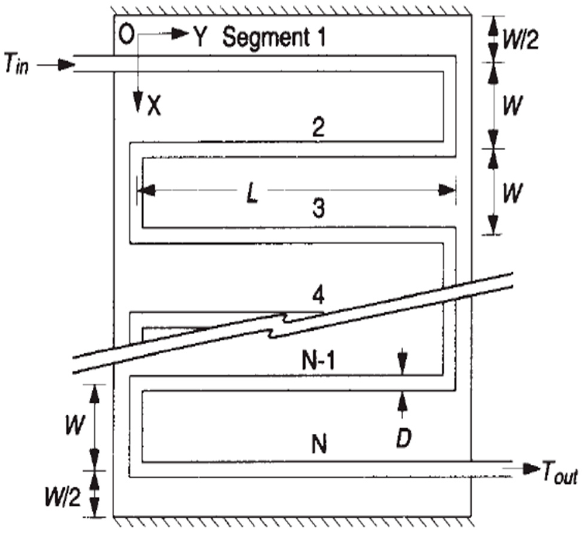
Evaluation of Heat Removal Factor
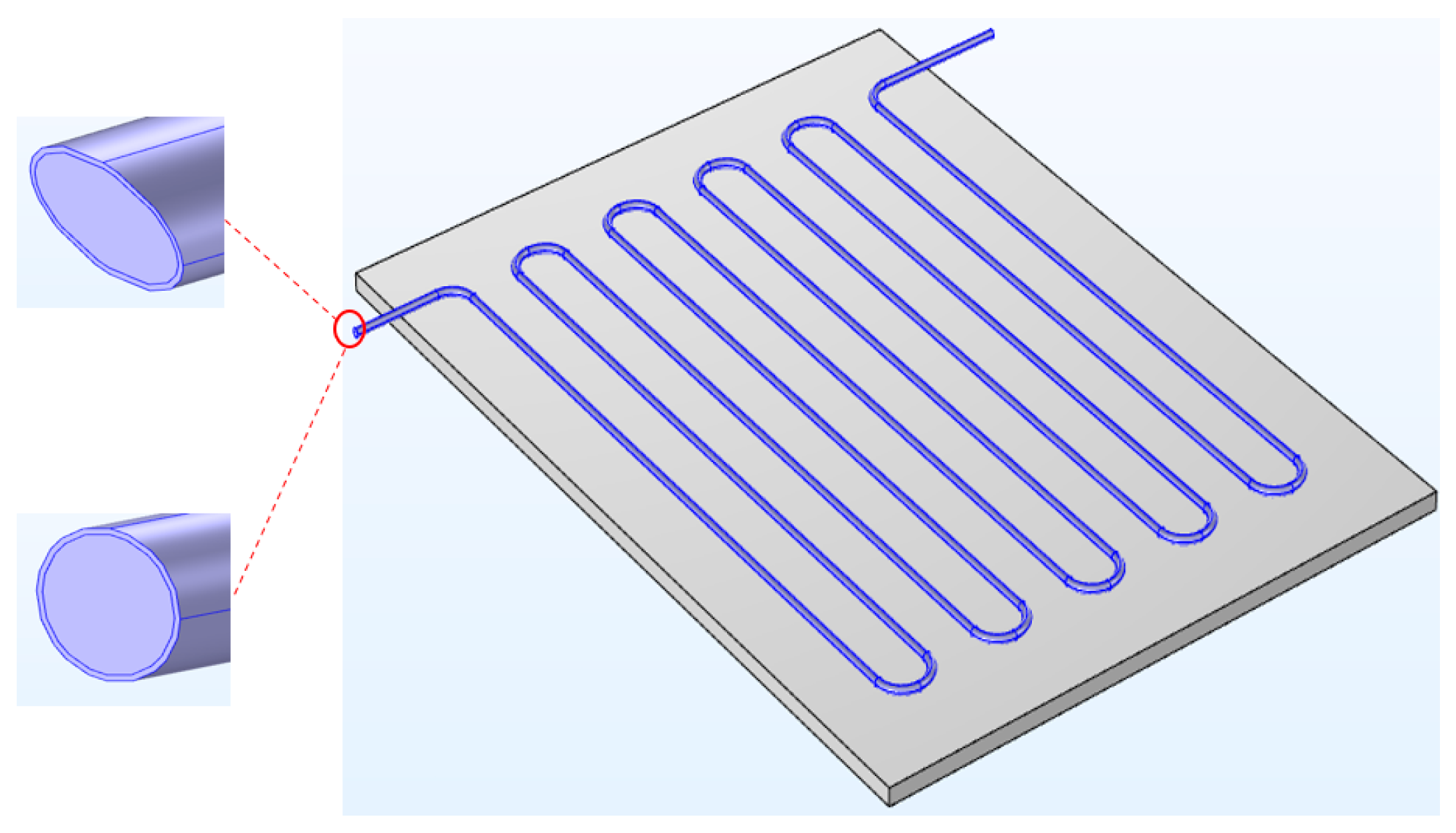
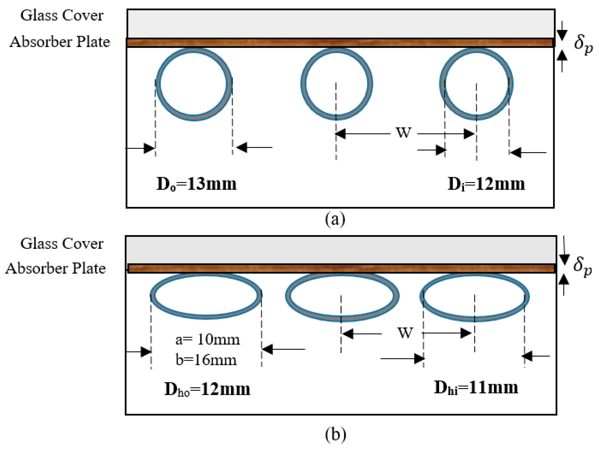
3. Design of the Flat Plate Solar Collectors with Elliptical and Circular Serpentine Tubes
4. Results and Discussion
5. Validation of Results
6. Conclusions
- The lower manufacturing costs and high efficiency even at low flow rates of circulating fluid are principal advantages of serpentine designs compared to their counterparts. However, they require pumping systems at higher flow rates.
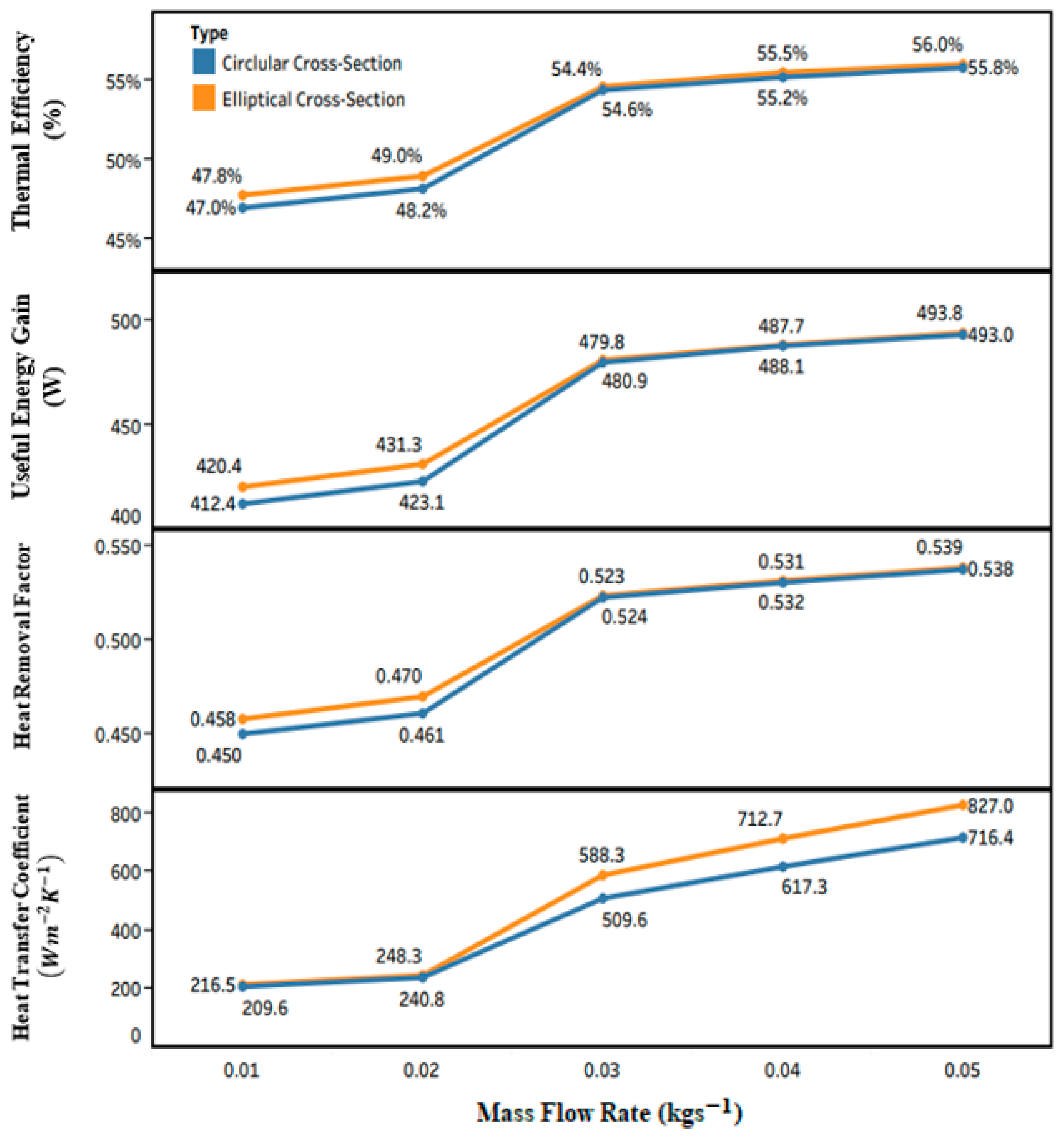
- The greatest values of were obtained for elliptical and circular cross-sections (493.8 W and 493 W, respectively) under turbulent flow ( of 0.05 kg s−1), even though the lowest values were 420.4 W and 412.4 W for circular and elliptical design under laminar flow ( 0.01 kg s−1), respectively. The maximum thermal efficiency (56%) is achievable under turbulent flow for the elliptical cross-section.
- The highest values of corresponded to elliptical and circular design under turbulent flow with 0.538 and 0.539, respectively, and was the minimum for circular and elliptical designs with 0.458 and 0.450, respectively, under laminar flow.
- At various mass flow rates, the tubes with different cross-sections lead to various values for , , , , , and , while the remains constant as it does not depend on the geometry of the tube.
- All heat transfer governing parameters increased notably by changing laminar to non-laminar flow rates for both cross-sections. It was due to the cooling effect of water showing better performance under non-laminar flow rates.
- It was concluded that at the same area, the cross-section geometry with lower values of hydraulic diameter (12 mm for elliptical design) had higher heat transfer characteristics in comparison to a cross-section with a greater hydraulic diameter (13 mm for circular design).
- At the same area, the elliptical tube increased the heat transfer rate () by approximately 2% in comparison to a circular tube due to a larger contact area between the working fluid and the solid surface of tubes.
Author Contributions
Funding
Institutional Review Board Statement
Informed Consent Statement
Data Availability Statement
Acknowledgments
Conflicts of Interest
Nomenclature
| a | minor axis of ellipse (m) |
| b | major axis of ellipse (m) |
| Ac | Collector area (m2) |
| Cb | Bound conductance (W/mK) |
| Cp | |
| Di | Inner diameter of the tube (m) |
| Do | Outer diameter of the tube (m) |
| Dh | Hydraulic diameter (m) |
| F1–F6 | Non-dimension parameters |
| FR | Heat removal factor |
| hfi | Heat transfer coefficient between fluid and tube wall (W/m2 K) |
| hw | Wind heat transfer coefficient (W/m2 K) |
| Kp | Thermal conductivity of absorber plate (W/m K) |
| Kw | Thermal conductivity of water (W/m K) |
| Kin | Thermal conductivity of insulation (W/m K) |
| k | Non-dimensional parameter |
| Lbl | Collector back length |
| Lbw | Collector back width |
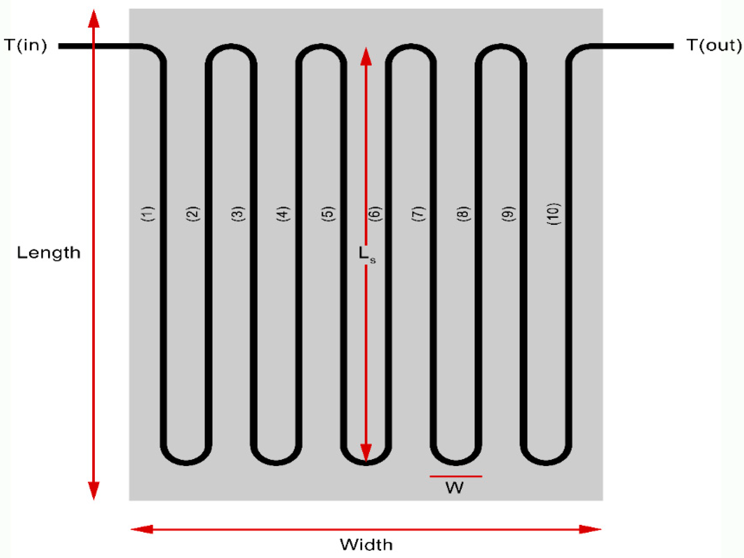
| Ls | Length of the serpentine segments |
| n | Non-dimensional parameter |
| N | Number of segments in serpentine tube |
| Ng | Number of the glass cover |
| The mass flow rate of circulating fluid (kg/s) | |
| Pc | Collector perimeter (m) |
| S | Absorbed solar energy (W/m2) |
| Ta | Ambient temperature (K) |
| Ti | Temperature of the inlet fluid (K) |
| To | Temperature of the outlet fluid (K) |
| Tm | Mean plate Temperature (K) |
| UL | Overall heat loss coefficient (W/m2 K) |
| W | Serpentine spacing (m) |
| Useful energy gain (W) | |
| Greek symbols | |
| α | Absorptance |
| Non-dimensional parameter | |
| Back insulation thickness (m) | |
| Edge insulation thickness (m) | |
| Thickness of collector (m) | |
| The thickness of the absorber plate (m) | |
| Glass emittance | |
| Plate emittance | |
| Thermal efficiency | |
| θ | Collector tilt |
| µd | |
| µb | |
| μw | |
| Density of water (kg/m3) | |
| τ | Transmittance |
References
- Alam, T.; Balam, N.B.; Kulkarni, K.S.; Siddiqui, M.I.H.; Kapoor, N.R.; Meena, C.S.; Kumar, A.; Cozzolino, R. Performance Augmentation of the Flat Plate Solar Thermal Collector: A Review. Energies 2021, 14, 6203. [Google Scholar] [CrossRef]
- Kumar, D.; Mahanta, P.; Kalita, P. Performance analysis of a solar air heater modified with zig-zag shaped copper tubes using energy-exergy methodology. Sustain. Energy Technol. Assess. 2021, 46, 101222. [Google Scholar] [CrossRef]
- Salari, A.; Kazemian, A.; Ma, T.; Hakkaki-Fard, A.; Peng, J. Nanofluid based photovoltaic thermal systems integrated with phase change materials: Numerical simulation and thermodynamic analysis. Energy Convers. Manag. 2020, 205, 112384. [Google Scholar] [CrossRef]
- Sarafraz, M.; Safaei, M.; Leon, A.; Tlili, I.; Alkanhal, T.; Tian, Z.; Goodarzi, M.; Arjomandi, M. Experimental Investigation on Thermal Performance of a PV/T-PCM (Photovoltaic/Thermal) System Cooling with a PCM and Nanofluid. Energies 2019, 12, 2572. [Google Scholar] [CrossRef]
- Abd Hamid, A.S.; Razali, H. Solar Car: Brief Review and Challenges. Borneo Sci. J. 2019, 40, 27–37. [Google Scholar]
- Lee, S.K.; Dayou, J.; Ag, A.S.; Saleh, E.; Ismail, B. A theoretical investigation on the potential application of ocean salinity and temperature energy conversion (OSTEC). Int. J. Renew. Energy Res. 2012, 2, 326–331. [Google Scholar] [CrossRef]
- Sukarno, K.; Hamid, A.S.A.; Jackson, C.H.W.; Pien, C.F.; Dayou, J. Comparison of power output between fixed and perpendicular solar photovoltaic PV panel in tropical climate region. Adv. Sci. Lett. 2017, 23, 1259–1263. [Google Scholar] [CrossRef]
- Sukarno, K.; Hamid, A.S.A.; Razali, H.; Dayou, J. Evaluation on cooling effect on solar PV power output using Laminar H2O surface method. Int. J. Renew. Energy Res. 2017, 7, 1213–1218. [Google Scholar]
- Javadi, F.S.; Metselaar, H.S.C.; Ganesan, P. Performance improvement of solar thermal systems integrated with phase change materials (PCM), a review. Sol. Energy 2020, 206, 330–352. [Google Scholar] [CrossRef]
- Siahkamari, L.; Rahimi, M.; Azimi, N.; Banibayat, M. Experimental investigation on using a novel phase change material (PCM) in micro structure photovoltaic cooling system. Int. Commun. Heat Mass Transf. 2019, 100, 60–66. [Google Scholar] [CrossRef]
- Sukarno, K.; Abd Hamid, A.S.; Dayou, J.; Makmud, M.Z.H.; Sarjadi, M.S. Measurement of global solar radiation in Kota Kinabalu Malaysia. ARPN J. Eng. Appl. Sci. 2015, 10, 6467–6471. [Google Scholar]
- Abd Hamid, A.S.; Ibrahim, A.; Assadeg, J.; Ahmad, E.Z.; Sopian, K. Techno-economic Analysis of a Hybrid Solar Dryer with a Vacuum Tube Collector for Hibiscus cannabinus L. Fibre. Int. J. Renew. Energy Res. 2020, 10, 1608–1613. [Google Scholar] [CrossRef]
- Koşan, M.; Demirtaş, M.; Aktaş, M.; Dişli, E. Performance analyses of sustainable PV/T assisted heat pump drying system. Sol. Energy 2020, 199, 657–672. [Google Scholar] [CrossRef]
- Yazdanifard, F.; Ameri, M. Exergetic advancement of photovoltaic/thermal systems (PV/T): A review. Renew. Sustain. Energy Rev. 2018, 97, 529–553. [Google Scholar] [CrossRef]
- Abd Hamid, A.S.; Makmud, M.Z.H.; Abd Rahman, A.B.; Jamain, Z.; Ibrahim, A. Investigation of Potential of Solar Photovoltaic System as an Alternative Electric Supply on the Tropical Island of Mantanani Sabah Malaysia. Sustainability 2021, 13, 12432. [Google Scholar] [CrossRef]
- Das, D.; Kalita, P.; Dewan, A.; Tanweer, S. Development of a novel thermal model for a PV/T collector and its experimental analysis. Sol. Energy 2019, 188, 631–643. [Google Scholar] [CrossRef]
- Dubey, S.; Tiwari, G.N. Thermal modeling of a combined system of photovoltaic thermal (PV/T) solar water heater. Sol. Energy 2008, 82, 602–612. [Google Scholar] [CrossRef]
- Zondag, H.A.; de Vries, D.W.; van Helden, W.G.J.; van Zolingen, R.J.C.; van Steenhoven, A.A. The thermal and electrical yield of a PV-thermal collector. Sol. Energy 2002, 72, 113–128. [Google Scholar] [CrossRef]
- Razali, N.F.M.; Fudholi, A.; Ruslan, M.H.; Sopian, K. Review of water-nanofluid based photovoltaic/thermal (PV/T) systems. Int. J. Electr. Comput. Eng. 2019, 9, 134. [Google Scholar] [CrossRef]
- Hamid, A.S.A.; Ibrahim, A.; Mat, S.; Sopian, K. Experimental evaluation on large scale solar dryer for drying natural fiber in Malaysia. Int. J. Renew. Energy Res. 2019, 9, 598–604. [Google Scholar]
- Ismail, A.F.; Abd Hamid, A.S.; Ibrahim, A.; Jarimi, H.; Sopian, K. Performance Analysis of a Double Pass Solar Air Thermal Collector with Porous Media Using Lava Rock. Energies 2022, 15, 905. [Google Scholar] [CrossRef]
- Jia, Y.; Alva, G.; Fang, G. Development and applications of photovoltaic–thermal systems: A review. Renew. Sustain. Energy Rev. 2019, 102, 249–265. [Google Scholar] [CrossRef]
- Rosli, M.A.M.; Misha, S.; Sopian, K.; Bin Mat, S.; Sulaiman, M.Y. Parametric Analysis on Heat Removal Factor for a Flat Plate Solar Collector of Serpentine Tube. World Appl. Sci. J. 2014, 29, 184–187. [Google Scholar] [CrossRef]
- Sekhar, R.; Sharma, K.; Rao, M. Evaluation of heat loss coefficients in solar flat plate collectors. J. Eng. Appl. Sci. 2009, 4, 15–19. [Google Scholar]
- Vokas, G.; Christandonis, N.; Skittides, F. Hybrid photovoltaic–thermal systems for domestic heating and cooling—A theoretical approach. Sol. Energy 2006, 80, 607–615. [Google Scholar] [CrossRef]
- Kalogirou, S.A.; Tripanagnostopoulos, Y. Hybrid PV/T solar systems for domestic hot water and electricity production. Energy Convers. Manag. 2006, 47, 3368–3382. [Google Scholar] [CrossRef]
- Pawar, V.R.; Sobhansarbandi, S. Design optimization and heat transfer enhancement of energy storage based solar thermal collector. Sustain. Energy Technol. Assessments 2021, 46, 101260. [Google Scholar] [CrossRef]
- Yeh, C.Y.; Boonk, K.J.F.; Sadeghi, G.; Mehrali, M.; Shahi, M.; Brem, G.; Mahmoudi, A. Experimental and numerical analysis of thermal performance of shape stabilized PCM in a solar thermal collector. Case Stud. Therm. Eng. 2022, 30, 101706. [Google Scholar] [CrossRef]
- Ahmad, E.Z.; Sopian, K.; Jarimi, H.; Fazlizan, A.; Elbreki, A.; Abd Hamid, A.S.; Rostami, S.; Ibrahim, A. Recent advances in passive cooling methods for photovoltaic performance enhancement. Int. J. Electr. Comput. Eng. 2021, 11, 146. [Google Scholar] [CrossRef]
- Korres, D.; Tzivanidis, C. Thermal analysis of a serpentine flat plate collector and investigation of the flow and convection regime. Therm. Sci. 2019, 23, 47–59. [Google Scholar] [CrossRef]
- Kumar, G.V.; Sridhar, K.; Kumar, S.A. Heat Removal Factor of an Integrated Solar Flat Plate Collector with Packed Bed System. Int. J. Eng. Technol. Manag. Appl. Sci. 2017, 5, 720–727. [Google Scholar]
- Allan, J.; Dehouche, Z.; Stankovic, S.; Mauricette, L. Performance testing of thermal and photovoltaic thermal solar collectors. Energy Sci. Eng. 2015, 3, 310–326. [Google Scholar] [CrossRef]
- Birhanu Oliy, G. Experimental Testing of a Serpentine Flat Plate Solar Water Heater. Int. J. Energy Power Eng. 2017, 6, 61. [Google Scholar] [CrossRef][Green Version]
- Al-Waeli, A.H.A.; Chaichan, M.T.; Sopian, K.; Kazem, H.A.; Mahood, H.B.; Khadom, A.A. Modeling and experimental validation of a PVT system using nanofluid coolant and nano-PCM. Sol. Energy 2019, 177, 178–191. [Google Scholar] [CrossRef]
- Sopian, K.; Alwaeli, A.H.A.; Kazem, H.A. Advanced photovoltaic thermal collectors. Proc. Inst. Mech. Eng. Part E J. Process Mech. Eng. 2020, 234, 206–213. [Google Scholar] [CrossRef]
- Abdullah, A.L.; Misha, S.; Tamaldin, N.; Rosli, M.A.M.; Sachit, F.A. Theoretical study and indoor experimental validation of performance of the new photovoltaic thermal solar collector (PVT) based water system. Case Stud. Therm. Eng. 2020, 18, 100595. [Google Scholar] [CrossRef]
- Singh, G.; Kumar, S.; Tiwari, G.N. Design, fabrication and performance evaluation of a hybrid photovoltaic thermal (PVT) double slope active solar still. Desalination 2011, 277, 399–406. [Google Scholar] [CrossRef]
- Agrawal, B.; Tiwari, G.N. Life cycle cost assessment of building integrated photovoltaic thermal (BIPVT) systems. Energy Build. 2010, 42, 1472–1481. [Google Scholar] [CrossRef]
- Tripanagnostopoulos, Y.; Nousia, T.; Souliotis, M.; Yianoulis, P. Hybrid photovoltaic/thermal solar systems. Sol. Energy 2002, 72, 217–234. [Google Scholar] [CrossRef]
- Wouters, V.P.; Bloem, J.J.; Zaaiman, W.J. Combined heat and power from hybrid PV building integrated components: Results from overall performance assessment. In Proceedings of the 2nd World Conference and Exhibition on PV Energy Conversion, Vienna, Austria, 6–10 July 1998; European Commission: Vienna, Austria. [Google Scholar]
- Faysal, S.R.; Ovi, I.R.Q.; Islam, A.K.M.S. Effect of aspect ratio on convective heat transfer for flat cross section using nanofluid. In AIP Conference Proceedings; AIP Publishing LLC: Dhaka, Bangladesh, 2017; Volume 1851, p. 020016. [Google Scholar]
- Sardouei, M.M.; Mortezapour, H.; Jafari Naeimi, K. Temperature distribution and efficiency assessment of different PVT water collector designs. Sādhanā 2018, 43, 84. [Google Scholar] [CrossRef]
- Razi, P.; Akhavan-Behabadi, M.A.; Saeedinia, M. Pressure drop and thermal characteristics of CuO–base oil nanofluid laminar flow in flattened tubes under constant heat flux. Int. Commun. Heat Mass Transf. 2011, 38, 964–971. [Google Scholar] [CrossRef]
- Xu, H.; Zhang, C.; Wang, N.; Qu, Z.; Zhang, S. Experimental study on the performance of a solar photovoltaic/thermal system combined with phase change material. Sol. Energy 2020, 198, 202–211. [Google Scholar] [CrossRef]
- Shah, R.; Srinivasan, P. Hybrid Photovoltaic and Solar Thermal Systems (PVT): Performance Simulation and Experimental Validation. Mater. Today Proc. 2018, 5, 22998–23006. [Google Scholar] [CrossRef]
- Al-Waeli, A.H.A.; Sopian, K.; Chaichan, M.T.; Kazem, H.A.; Ibrahim, A.; Mat, S.; Ruslan, M.H. Evaluation of the nanofluid and nano-PCM based photovoltaic thermal (PVT) system: An experimental study. Energy Convers. Manag. 2017, 151, 693–708. [Google Scholar] [CrossRef]
- Jarimi, H.; Abu Bakar, M.N.; Othman, M.; Din, M.H. Bi-fluid photovoltaic/thermal (PV/T) solar collector: Experimental validation of a 2-D theoretical model. Renew. Energy 2016, 85, 1052–1067. [Google Scholar] [CrossRef]
- Ibrahim, A.; Othman, M.Y.; Sopian, K.; Ruslan, M.H.; Alghoul, M.; Yahya, M.; Zaharim, A. Performance of Photovoltaic Thermal Collector (PVT) with Different Absorbers Design. WSEAS Trans. Environ. Dev. 2009, 5, 321–330. [Google Scholar]
- Abdel-Khalik, S.I. Heat removal factor for a flat-plate solar collector with a serpentine tube. Sol. Energy 1976, 18, 59–64. [Google Scholar] [CrossRef]
- Malvi, C.S.; Gupta, A.; Gaur, M.K.; Crook, R.; Dixon-Hardy, D.W. Experimental investigation of heat removal factor in solar flat plate collector for various flow configurations. Int. J. Green Energy 2017, 14, 442–448. [Google Scholar] [CrossRef]
- Zhang, H.-F.; Lavan, Z. Thermal performance of a serpentine absorber plate. Sol. Energy 1985, 34, 175–177. [Google Scholar] [CrossRef]
- Akgün, M.A. Heat removal factor for a serpentine absorber plate. Sol. Energy 1988, 41, 109–111. [Google Scholar] [CrossRef]
- Duffie, J.A.; Beckman, W.A. Solar Engineering of Thermal Processes. Am. J. Phys. 2013, 53, 944. [Google Scholar] [CrossRef]
- Lund, K.O. General thermal analysis of serpentine-flow flat-plate solar collector absorbers. Sol. Energy 1989, 42, 133–142. [Google Scholar] [CrossRef]
- Dezfouli, M.M.S.; Yazid, M.Z.A.; Zakaria, A.; Ahmed, S.F.; Ali, A.; Moghimi, S. Application of high efficiency motors in HVAC system for energy saving peurpos. In Proceedings of the IEEE International Conference on Innovative Research and Development (ICIRD), Bangkok, Thailand, 11–12 May 2018; pp. 1–5. [Google Scholar] [CrossRef]
- Mills, A.F. Heat Transfer, 2nd ed.; CRC Press: Boca Raton, FL, USA, 1998; ISBN 0139476245. [Google Scholar]
- Hussein, A.M.; Sharma, K.V.; Bakar, R.A.; Kadirgama, K. The effect of cross sectional area of tube on friction factor and heat transfer nanofluid turbulent flow. Int. Commun. Heat Mass Transf. 2013, 47, 49–55. [Google Scholar] [CrossRef]
- Al-Tajer, A.M.; Kramallah, A.A.; Mohsen, A.M.; Mahmoud, N.S. Experimental investigation of heat transfer of nanofluid in elliptical and circular tubes. Math. Model. Eng. Probl. (IIETA) 2021, 8, 665–671. [Google Scholar] [CrossRef]


| Authors | Year of Study | Cross-Section | Type of Study | Location |
|---|---|---|---|---|
| Xu et al. [44] | 2020 | Circular | Experimental | China |
| Korres and Tzivanidis [30] | 2018 | Circular | theoretical | Greece |
| Shah et al. [45] | 2018 | Circular | Experimental and simulation | India |
| Al-Waeli et al. [46] | 2017 | Circular | Experimental | Malaysia |
| Jarimi et al. [47] | 2016 | Circular | theoretical and experimental | Malaysia |
| Rosli et al. [23] | 2014 | Circular, rectangular, and square | Theoretical | Malaysia |
| Ibrahim et al. [48] | 2009 | Circular | Theoretical and simulation | Malaysia |
| Components | Material | Optical and Thermal Properties | |
|---|---|---|---|
| Metal box | Aluminum | 35 mm | |
| Cover | Glass with anti-reflecting coating | 5 mm | |
| Metal absorber plate | Zinc oxide | 1 mm | |
| Serpentine tubes | copper | 1 mm | |
| Back insulation | Glass wool | 20 mm | |
| Side insulation | Glass wool | 20 mm |
| Symbols | Parameters | Values |
|---|---|---|
| Ls | Length of the serpentine segments | |
| W | Serpentine spacing | |
| N | Number of segments in the serpentine tube | 10 |
| Ac | Collector area | |
| Cp | ||
| Kw | ||
| Ta | Ambient temperature | |
| Tm | Mean plate Temperature | |
| Ti | Inlet fluid temperature | |
| Collector tilt | ||
| Lbl | Collector back length | |
| Lbw | Collector back width | |
| Pc | Collector perimeter | |
| hw | Wind heat transfer coefficient | |
| µd | ||
| µb | ||
| μw | ||
| Stephen Boltzmann constant | ||
| S | Absorbed solar energy | |
| ) |
Publisher’s Note: MDPI stays neutral with regard to jurisdictional claims in published maps and institutional affiliations. |
© 2022 by the authors. Licensee MDPI, Basel, Switzerland. This article is an open access article distributed under the terms and conditions of the Creative Commons Attribution (CC BY) license (https://creativecommons.org/licenses/by/4.0/).
Share and Cite
Rostami, S.; Abd Hamid, A.S.; Sopian, K.; Jarimi, H.; Bassim, A.; Ibrahim, A. Heat Transfer Analysis of the Flat Plate Solar Thermal Collectors with Elliptical and Circular Serpentine Tubes. Appl. Sci. 2022, 12, 4519. https://doi.org/10.3390/app12094519
Rostami S, Abd Hamid AS, Sopian K, Jarimi H, Bassim A, Ibrahim A. Heat Transfer Analysis of the Flat Plate Solar Thermal Collectors with Elliptical and Circular Serpentine Tubes. Applied Sciences. 2022; 12(9):4519. https://doi.org/10.3390/app12094519
Chicago/Turabian StyleRostami, Shirin, Ag Sufiyan Abd Hamid, Kamaruzzaman Sopian, Hasila Jarimi, Anwor Bassim, and Adnan Ibrahim. 2022. "Heat Transfer Analysis of the Flat Plate Solar Thermal Collectors with Elliptical and Circular Serpentine Tubes" Applied Sciences 12, no. 9: 4519. https://doi.org/10.3390/app12094519
APA StyleRostami, S., Abd Hamid, A. S., Sopian, K., Jarimi, H., Bassim, A., & Ibrahim, A. (2022). Heat Transfer Analysis of the Flat Plate Solar Thermal Collectors with Elliptical and Circular Serpentine Tubes. Applied Sciences, 12(9), 4519. https://doi.org/10.3390/app12094519