Abstract
Repetitive loads acting on the hip joint fluctuate according to the type of activities produced by the human body. Repetitive loading is one of the factors that leads to fatigue failure of the implanted stems. The objective of this study is to develop lightweight femoral stems with cubic porous structures that will survive under fatigue loading. Cubic porous structures with different volumetric porosities were designed and subjected to compressive loading using finite element analysis (FEA) to measure the elastic moduli, yield strength, and ultimate tensile strength. These porous structures were employed to design femoral stems containing mechanical properties under compressive loading close to the intact bone. Several arrangements of radial geometrical porous functionally graded (FG) and homogenous Ti-6Al-4V porous femoral stems were designed and grouped under three average porosities of 30%, 50%, and 70% respectively. The designed stems were simulated inside the femoral bone with physiological loads demonstrating three walking speeds of 1, 3, and 5 km/h using ABAQUS. Stresses at the layers of the functionally graded stem were measured and compared with the yield strength of the relevant porous structure to check the possibility of yielding under the subjected load. The Soderberg approach is employed to compute the safety factor (Nf > 1.0) for each design under each loading condition. Several designs were shortlisted as potential candidates for orthopedic implants.
1. Introduction
Total hip arthroplasty (THA) is a successful treatment procedure that helps patients achieve pain free movement by hip replacement [1,2]. The cementless femoral stems are introduced in the femur medullary canal and securely fixed to the bone to create a direct press-fit contact to transfer part of the applied loads developed during human daily activities to the adjacent bone [2,3,4]. The femoral stems were designed to live for a minimum of 20 years. However, the life span of the hip implants is affected by many limitation factors leading to stem failure [2]. Fatigue fracture is one of the major problems associated with femoral stem failures [5,6]. In addition, other factors include micromotion (that may lead to poor bone tissue ingrowth), stress shielding (where the stem doesn’t transfer the applied load to the adjacent bone and, as a consequence, may cause aseptic loosening, stem migration), and failure, surrounding bone fractures and requiring revision surgery [3,7,8,9,10]. The proposed solution is to use the mechanical properties of the stem material that can be controlled by introducing porous cellular structure to reduce the modulus of elasticity and yield strength as concluded in our previous study [11,12]. THA revision surgery is more complex compared with the primary one due to the higher risk and unsatisfactory outcomes in terms of further loss of the host bone, perforation, fracture, pain, time, and cost aspects [2,13,14,15].
Total hip arthroplasty is keep raising drastically over the next 30 years. THA in USA is expected to increase from 930,575 in 2020 to 1,537,422 in 2050 with an annual growth rate of 1.7% [15,16]. The revision hip replacement surgery after 20 years varies from 40% for young of less than 50 years old, 30% for ages between 50 and 59 years old, and 15% for ages between 60 and 75 years old [16]. Early hip arthroplasty revisions with a diagnosis of infection and inflammatory reaction, fracture, instability, other mechanical complications, and aseptic loosening over the years 2012 to 2019 are 32.5%, 24.3%, 21,7%, 4.8%, and 4.2%, respectively [15,17].
The femoral stem’s prefabricated design allows using different biocompatible materials with properties fitting the functional requirements [2,18] and increasing the expectations to last longer than before. Studies have proven that the Ti-6Al-4V (Ti alloy) is a perfect biomedical material for hip implants in terms of strength, biocompatibility, corrosion resistance, lightweight, and flexibility [19,20,21]. The stiffness of the Ti-6Al-4V alloy is 5 -10 stiffer than femur bone [11,20]. Thus, stems with porous structure designs were developed to reduce the stiffness, enhance the trabecular bone tissue ingrowth that facilitates the integration of the implanted stem with the hosting bone [22] and significantly reduce the stress shielding [11]. The applied forces on the implanted stem that depend on the different human activities such as running, stair climbing, jogging, and walking at various speeds produce dynamic stresses leading to fatigue fracture [23]. Many researchers focused on transferring part of the applied stresses on the stem to the bone to reduce the stress shielding and micromotion without considering the fatigue failure due to the dynamic stresses in their studies. Most of the previous studies were found predicting the fatigue limit using FEA for bulk stems under concentrated compression loads, but few studies were found carried out for stems with porous structure [24,25]. No literature was discovered on computing the fatigue life for porous stems using different physiological loads.
In our previous study [11], mechanical performance, stress shielding, and micromotion of the designed femoral stems were studied and investigated. To complete the investigations to have the most ideal design that can be recommended for the surgent based on patients’ conditions, it is vital to study the fatigue performance of the proposed designs. Hence, this current study aims to investigate the performance of the designed functionally graded porous structures femoral stem under high cyclic loads, focusing on the stresses obtained on each of the stem’s layers and fatigue factor of safety for each stem. The hypothesis in this study is that such radial functionally graded porous structure will provide optimum designs that can reduce the stress shielding, promote the stability and survive under high cyclic loading focusing on the level of porosity in the stems required to achieve good biomechanical performance. Hence, in this study, Fifteen Ti-6Al-4V functionally and homogeneous fully porous stems were designed and grouped under three average volumetric porosities, namely, 30%, 50%, and 70%. The porosities were integrated into the stem and geometrically arranged in the radial direction using cubic porous structures and tested using 3D Finite Element model (ABAQUS) under physiological loads based on slow (1 km/h), medium (3 km/h), and fast walking speeds (5 km/h) [11]. The stresses within the stem’s porous layers were measured to verify and ensure the designs are safe under certain loading conditions based on the yield strength of the porous structure and fatigue factor of safety limit (Nf > 1.0) [24]. The factor of safety is calculated for each design using the Soderberg approach. This approach is efficient in terms of estimating the stem fatigue limit under high cyclic loads [24].
2. Material and Methods
In this section, various essential aspects are described in detail, including the finite element model details for both porous microstructure and femoral stems, mechanical behavior of the designed stems under physiological loading conditions aiming to predict the fatigue life of the designed functionally graded porous stems.
2.1. Finite Element Model
2.1.1. Porous Microstructure
Square pores microstructure three-dimensional (3D) models with various volumetric porosities ranging from 10% to 90% were designed and simulated under compression loading using ABAQUS 6.17 as illustrated in Figure 1 and presented in Table 1. The square pores’ structure was selected based on the results of a previous fatigue study carried out by Amin Yavari et al. [26] on different Ti-4Al-6V alloy porous structures. The experimental results show the superiority of the cubic porous structures over the other structures such as diamond shape structures. None of the cubic porous structure specimens failed under fatigue testing even at a maximum load of 80% of the relevant porous structure yield strength (0.8σYs). These porous cubic structures reached 106 loading cycles without signs of failure. This is attributed to the vertical struts performing better than the diagonal and horizontal ones in compression loading conditions [26,27].
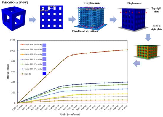
Figure 1.
Porous structure designs sample for finite element model to study the mechanical properties of different volumetric porosities.

Table 1.
Designed samples of porous cubes with the relevant volumetric porosities and obtained mechanical properties from the FEA.
Different sizes of square pores with minimum strut thicknesses of 3.0 mm [26] were fitted within 15 mm × 15 mm × 15 mm 3D cubes. The volumetric porosity percentages were calculated based on the volume of the square pores introduced to the 3D cubes based on Equation (1) generated in our previous study [11]. The top and bottom sides of the cubes were fitted with plates; a displacement boundary condition was assigned to the top plate; and a encastre boundary condition was used to tie up the bottom plate. The designed structures were assigned with bulk Ti-4Al-6V material properties. C3D10 quadratic tetrahedral meshing elements had been used to mesh the assembly using a mesh size of 0.2 mm based on a sensitivity study determined from stiffness convergence of dense cube [11].
where:
- Vp: Volumetric porosity
- L2: cubic pore inner dimension
- N: Number of pores in a single cube face
- x: Full cube dimension
- t: Strut thickness
The upper plate was assigned with axial displacement to attain the yield points using 0.05 increment size to generate more accurate values of the yield points, modulus of elasticity, and ultimate tensile strength. Mass properties in ABAQUS were used to compare the designed volumetric porosity for each designed cube.
2.1.2. Porous Stem Design
The designed porous cellular structures were utilized to design twelve different functionally graded porous stems and three homogeneous porous stems with average volumetric porosities of 30%, 50%, and 70%. Additional porous structures were designed that are needed for designing these 15 stems as shown in Figure 2. The fifteen designed stems were divided into three groups representing these aforementioned average volumetric porosities, each group contains four functionally graded designs and one homogeneous design The functionally graded porous structures were created within the stem’s layers in the radial direction, the layers cross-sectional areas are 15.9 mm2, 17.3 mm2, and 23.6 mm2 for L1 (the stem’s core), layer 2 (L2), and layer 3 (L3), respectively. Figure 2 illustrates the porosities configurations within the stem’s layers to achieve the required overall average volumetric porosity of the pertinent group. The average porosities of the designed stems in a radial direction were calculated based on Equation (2).
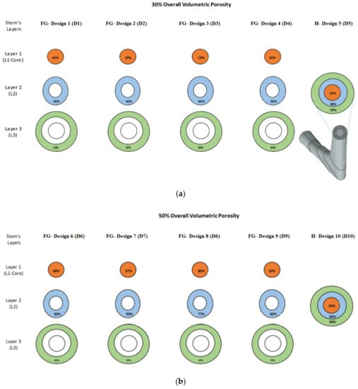
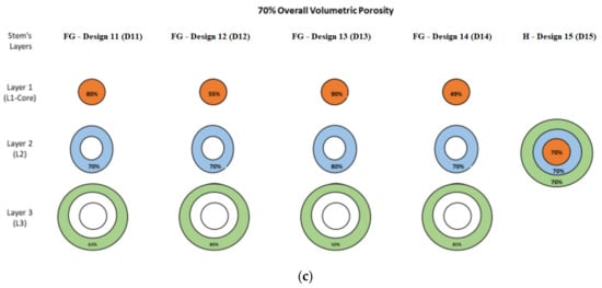
Figure 2.
Design groups of porous functionally graded (FG) and homogeneous designs introduced to stem’s redial layers: (a) average porosity of 30%, (b) average porosity of 50%, and (c) average porosity of 70%.
These fifteen designs (D1 to D15) were integrated into three-dimensional (3D) finite element models in ABAQUS 6.17 software to study the mechanical behavior of the designed stems under physiological loading conditions obtained from walking at speeds of 1 km/h, 3 km/h, and 5 km/h. The stem-bone assembly as shown in Figure 3 was built based on ISO 7206-4 standard [11,28] using surface to surface contact between the stem and the bone interface surfaces with a 0.4 friction coefficient. The assembly was fixed into cylindrical shape epoxy (3.7 GPa) with specific orientations shown in Figure 3, the bone was tied with the epoxy and constrained to move or revolve in any direction [7]. The 3D model of the femur was constructed using computed tomography (CT) scanned images of a patient femur as explained in previous studies [7,29]. Cortical and trabecular bone were considered homogeneous and linear elastic isotropic material, respectively, with material properties as listed in Table 2 [24,30,31].
where
- A: Stem’s radial Layer cross-sectional Area
- : Stems radial Layer Volumetric Porosity
- : Average functionally graded Porosity along the stem’s layers
- : Average homogeneous Porosity along the stem’s layers
- : Stem Homogenous porosity.
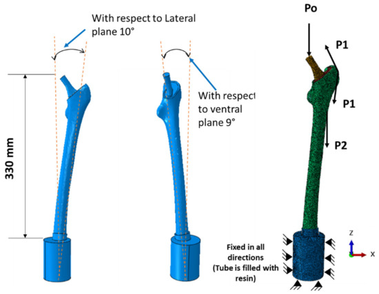
Figure 3.
Stemmed femur complete finite element model with applied physiological loads.
Table 2.
Femur material properties utilized for the finite element model [8,35].
Table 2.
Femur material properties utilized for the finite element model [8,35].
| Bone Material | Young’s Modulus (GPa) | Shear Modulus (GPa) | Poisson’s Ratio |
|---|---|---|---|
| Spongy Bone (Trabecular bone) | 0.4 | ||
| Cortical bone | Exx = 11.5 | Gxy = 3.6 | νxy = 0.51 |
| Eyy = 11.5 | Gyz = 3.3 | νyz = 0.31 | |
| Ezz = 17 | Gzx = 3.3 | νzx = 0.31 |
The femur was subjected to three physiological loads, specifically hip contact force (P0) and muscular forces (P1 and P2) [11,32,33], as shown in Figure 3. The applied forces in their components Fx, Fy, and Fz were calculated based on an average bodyweight of 900 N at different walking speeds (i.e., 1 km/h, 3 km/h, and 5 km/h) as shown in Table 3. The highest hip contact forces used in percent of bodyweight (%BW) were 293%, 352%, and 471% for walking speeds of 1 km/h, 3 km/h, and 5 km/h, respectively [32,33].
Table 3.
Bodyweight and muscular loads for different walking speeds [11,32,33].
The assembly was meshed with a mesh size of 3 mm using C3D10 quadratic tetrahedral elements as illustrated in Figure 3, which was used based on a previous sensitivity study [11,34].
2.2. Fatigue Analysis of the Designed Porous Stems
A fatigue study was performed on the designed stems implanted inside bone by performing finite element analysis based on physiological loading conditions obtained from the three walking speeds as presented in Table 3. Von Mises stress on the stem/stem layers was measured using ABAQUS FEA software and the results were used to calculate the factor of safety as illustrated in Figure 4. Designs D12 and D14 denote that no results were obtained as the FEA simulation does not converge due to the high volumetric porosity at the outer layer of these stems (Figure 4) [11].
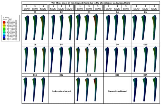
Figure 4.
Von Mises stress obtained from the FEA for the fifteen designed stems planted inside the femur and subjected to the three physiological loads (1 km/hr, 3 km/hr, and 5 km/hr).
The Soderberg approach was used for calculating the factor of safety [24] as shown in Equations (3)–(6):
The minimum stresses and the maximum stresses were measured at the loads associated with a stress ratio of 0.1 (R = 0.1) during the test:
where; (σm) and (σa) denote mean and alternating stresses generated in the porous stems and (σmin) and (σmax) are refereeing to minimum stresses at 0.1 of the applied physiological load and maximum stresses associated with the full load generated from each walking speed.
Hence, the fatigue factor of safety Nf is as follows:
Whereas Se, Sys, and N denote the endurance limit of the porous material calculated using Equation (7) [36], yield strength of the porous material, and factor of safety, respectively.
- : Surface quality factor.
- : Size factor.
- : Reliability factor.
- : Temperature factor.
- : Stress concentration factor.
- : Miscellaneous factor.
- For Ti6Al4V [37]: 0.54
: The Ultimate tensile stress of the porous material, (the for the outer stem’s porous layer for each design was used where it’s associated with the maximum stresses obtained from each walking speed), the reduction percentage in and the calculated endurance limit are shown in Table 4 below:
Table 4.
The obtained elastic moduli, yield strength, ultimate tensile strength, and the associated calculated of the endurance limit values based on the percentage of reduction in due to the introduced porosities.
3. Result and Discussion
Simple cubic microstructure (squire bore) with different volumetric porosities were designed and simulated under compression loading test to estimate the mechanical properties associated with each design. Stress-strain diagram for each sign was plotted (Figure 1) to obtain the yield strength, ultimate tensile stress, and elastic moduli, and the results were listed in Table 4. The results were used for designing and modeling the 15 stems which were grouped under three average volumetric porosities (namely 30%, 50%, and 70%) as shown in Figure 2.
Static finite element analysis (FEA) of the stem-bone assembly was performed for the fifteen designed functionally graded and homogeneous porous stems by applying the physiological loading conditions of the three walking speeds as illustrated in Table 3. Force-displacement data from the porous stem were used to validate the finite element models as explained in our previous study [11].
3.1. Mechanical Properties of the Porous Structures
Mechanical properties of the cubic porous structures were obtained to study the fatigue life and the factor of safety of the designed stems. It was observed that as the porosity increase the yield strength and elastic moduli decrease as presented in Table 4 and illustrated in Figure 5. A bulk Ti cube with the same dimensions was simulated using the same boundary conditions for validation and comparison purposes, the computed effective Young’s Modulus was 123.6 GPa, which shows a good agreement with Hedayati et. al. results of 122.6 GPa [38].
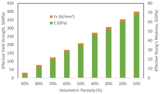
Figure 5.
Finite element analysis mechanical properties of the porous structures under compression loading.
3.2. Stresses in Porous Stem Layers
3.2.1. Stem-Bone Model Validation
A bulk Ti stem was simulated inside the femur by applying a concentrated force of 3000 N in ten increments with increment size of 300 N at the stem head. Force-displacement data were plotted by tracking the displacement values at a certain point on the femur head as illustrated in Figure 6, the results were compared with Jette et al. finite element model results [19] for our model validation using the same boundary conditions test data, a strong agreement was noticed between both models as shown in Figure 6.
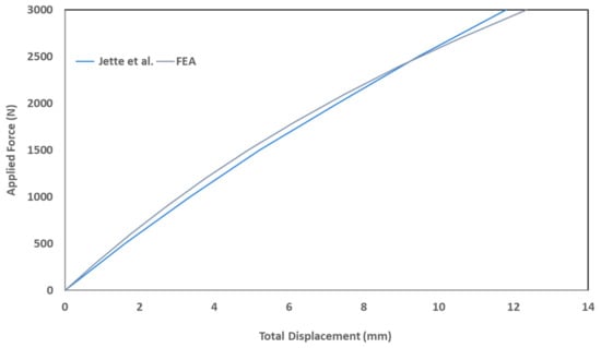
Figure 6.
Stem-bone model validation of bulk stem against Jett el. al. FE results [11,19].
It can be concluded from this validation result that the difference in implant geometry between Jette et al. [19] and our model has less impact on the results. The slight difference in the curves can be attributed to the difference in the exact position of the selected point on the bone head.
3.2.2. Stresses in Porous Stem’s Section
The stresses within each porous layer were computed through the FEA results for the fifteen FG designs and for each of the three walking speeds (as illustrated in Figure 7). The stresses within the stem’s layers are increasing radially up to reach the maximum stress at the outer stem’s layer (L3). The stresses associated with layer 3 (L3) were considered for the fatigue calculations as this layer is associated with the maximum stress and on direct contact with the bone. Stresses at the outer layer (L3) of the porous stems were found to be less than the stresses generated on the bulk stem for all designs and walking speeds, which indicates that the applied loads/stresses are distributed between the femur and the stem (more stress transfer to the femur). This is attributed to the reduction of the stiffness associated with each porous stem designs in comparison with the bulk stem stiffness (114 GPa). Hence, the stress level is on the stem is affected by two factors: the applied loads associated with the walking speeds and the stiffness of the designed stems. Although the stress distribution along the FG stem’s layers was varied, this is attributed to the difference in the Young’s modulus of each porous layer. The yield strength was studied for each stem’s porous layer and compared with the stress values computed via FEA of the stem-bone models and found that all designs are not yielding at walking speed of 1 km/h except designs 9, 12 which holds stress value at the stem’s outer layer equal to the yield strength value related to 70% and 80% porosities, respectively, and design 14 which gave no results. At 3 km/h walking speed only designs 1, 3 and 8 were observed to be not yielding and safe. All designs found to be yielded at walking speed of 5 km/h as the stresses encountered are higher than the yield strength associated with the relevant porous structure of each design. stem’s failure (SF) is calculated based on the stress ratio between the relevant stem layer yield strength and the maximum stress value of that layer ( based on Equation (8):
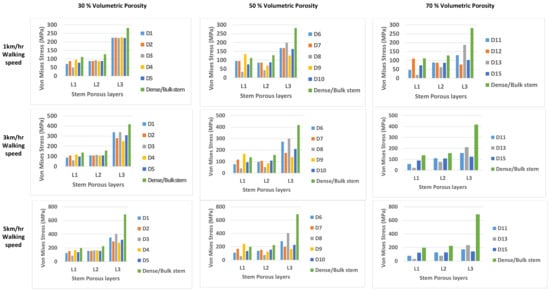
Figure 7.
Stresses within each porous layer were computed through the FEA results for the fifteen FG designs and for each of the three walking speeds: 1 km/hr, 3 km/hr, and 5 km/hr walking speed.
The design will not fail/yield if SF value > 1.0, the results are illustrated in Figure 8.
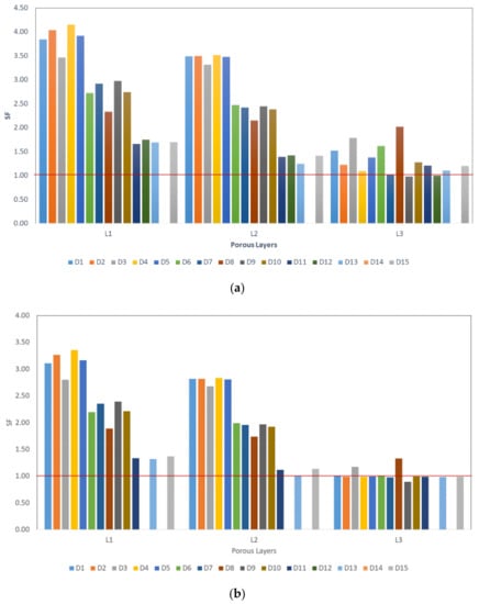
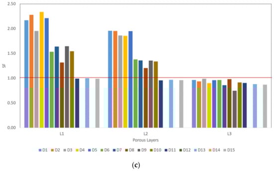
Figure 8.
Stress ratio between the relevant stem layer yield strength and the maximum stress value of that layer (; (a) at 1 km/h walking speed, (b) at 3 km/h walking speed, and (c) at 5 km/h walking speed.
Previous experimental study Amin Yavari et al. [26] shows the superiority of the cubic porous structures over the other structures such as diamond shape structures. None of their cubic structure tested samples were failed under cyclic loading at maximum load of 80% of the relevant porous structure yield strength (0.8σYs) [26]. This finding is comparable with our computational analysis findings up to certain loading conditions as illustrated in Figure 8.
3.3. Fatigue Factor of Safety (Soderberg Approach)
The fatigue factor of safety is one of the important factors used for the evaluation of the femoral stem’s durability [23]. Taking into consideration the other factors that need to be included in the porous femoral stem design such as stress shielding, micromotion for enhancing the implant’s stability through improving bone tissue ingrowth in order to avoid premature implant failures. Stresses encountered within the stem during the daily activities shall be computed and compared with the yield strength of the used porous structure [39,40]. Most of the previous studies were predicting the fatigue limit using FEA for solid stems and under concentrated compression load, and less studies were found for porous stem [24,25]/No literature was discovered on computing the fatigue life for FG porous stems in the radial direction using different physiological loads. Hence, in this study, the factor of safety was calculated for each design using Soderberg approach. This approach is efficient in terms of estimating the stem fatigue limit under high cyclic loads [24] and this approach provide the worst-case scenario among the other approaches (namely, Goodman and Gerber [24]).
The maximum and the minimum stress were identified based on increments 1 and 10 of the FEA (ABAQUS) results, i.e., the cyclic stress ratio of R = 0.1 for calculating the minimum and maximum stresses as shown in Equations (3)–(6). The factors of safety () were calculated and the results for all designs with the three walking speeds are shown in Figure 9. The designs that have a factor of safety > 1 are considered safe under cyclic fatigue loading. None of the fifteen designs were found to be safe under a walking speed of 5 km/h. only Design 8 (D8) is safe to be used up to a walking speed of 3 km/h and the von Mises stress is less the associated yield strength at 1 km/h and 3 km/h. Designs D1, D2, D3, D5, D6, D8, D10, D11, and D15 are safe under walking speeds of 1 km/h all of these designs also had von Mises stresses less than their associated yield strength at 1 km/h walking speed. Most of the THA patients are normally have a maximum normal walking speed of 1.54 km/h and this level is less for the elderly patients [41,42].
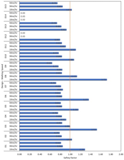
Figure 9.
Soderberg factors of safety obtained for the designed stems under the three loading conditions. (0.0 values shown for D12 and 14 denotes that no results obtained as the FEA simulation does not converge due to the high volumetric porosity at the outer layer of the stem).
The proposed femoral stem designs can be improved to enhance the fatigue factor of safety by adding an outer dense shell to the porous stem structure with different thicknesses [3] which will be part of our future study.
4. Conclusions
The aim of this study is to identify the fatigue durability of the cementless functionally graded and homogeneous porous structure femoral stems. Fifteen different volumetric porosities arrangements within the stems layers in a radial direction were grouped into three average porosities of 30%, 50%, and 70%. Different physiological loading conditions corresponding to three walking speeds (1 km/h, 3 km/h, and 5 km/h) were applied on the stem-femoral bone assembly. The von Mises stresses were computed within the stem’s layers and studied against the yield strength associated with the relevant porous layer porosity. Fatigue factors of safety were computed for each design under the three loading conditions using Sodeberg approach. The outcomes obtained from this study lead to the following conclusions:
The porous structure’s mechanical properties varied as the volumetric porosities changed and this is affecting the stems performance and fatigue endurance under daily human physical activities;
Changing the porosities arrangement within the stem’s layers affects the stems durability and the fatigue performance;
Designs D1, D2, D3, and D5 with volumetric percentage of 30%, D6, D8, and D10 with volumetric percentage of 50%, and D11 and D15 with volumetric percentage of 70% were found to be safe at walking speed 1 km/h in terms of von Mises stress values compared with the associated yield strength and factor of safety based on Soderberg approach;
Design 8 (D8) is the best candidate that found not failed up to walking speed of 2 km/h.
The performance of the proposed designs can be enhanced by adding outer dense shell to the porous stem structures with different thicknesses which will be part of our future study.
Author Contributions
Formal analysis, N.F.A.Z.; Funding acquisition, F.T.; Investigation, N.F.A.Z.; Supervision, F.T. and H.M.; Writing–original draft, N.F.A.Z.; Writing–review & editing, F.T. and H.M. All authors have read and agreed to the published version of the manuscript.
Funding
The APC was funded by QNRF grant no NPRP 8-876-2-375 from the Qatar National Research Fund (a member of Qatar Foundation). The findings achieved herein are solely the responsibility of the authors.
Institutional Review Board Statement
Not applicable.
Informed Consent Statement
Not applicable.
Data Availability Statement
Not applicable.
Conflicts of Interest
The authors declare no conflict of interest.
References
- Petrolo, L.; Testi, D.; Taddei, F.; Viceconti, M. Effect of a virtual reality interface on the learning curve and on the accuracy of a surgical planner for total hip replacement. Comput. Methods Programs Biomed. 2010, 97, 86–91. [Google Scholar] [CrossRef] [PubMed]
- Holzwarth, U.; Cotogno, G. Total Hip Arthroplasty: State of the Art, Prospects and Challenges; European Commisson: Brussels, Belgium, 2012. [Google Scholar] [CrossRef]
- Mehboob, H.; Tarlochan, F.; Mehboob, A.; Chang, S.-H.; Ramesh, S.; Harun, W.S.W.; Kadirgama, K. A novel design, analysis and 3D printing of Ti-6Al-4V alloy bio-inspired porous femoral stem. J. Mater. Sci. Mater. Med. 2020, 31, 78. [Google Scholar] [CrossRef] [PubMed]
- Harrison, N.; Field, J.R.; Quondamatteo, F.; Curtin, W.; McHugh, P.E.; Mc Donnell, P. Preclinical trial of a novel surface architecture for improved primary fixation of cementless orthopaedic implants. Clin. Biomech. 2014, 29, 861–868. [Google Scholar] [CrossRef] [PubMed]
- Zameer, S.; Haneef, M. Fatigue Life Estimation of Artificial Hip Joint Model Using Finite Element Method. Mater. Today Proc. 2015, 2, 2137–2145. [Google Scholar] [CrossRef]
- Lin, Y.-T.; Wu, J.S.-S.; Chen, J.-H. The study of wear behaviors on abducted hip joint prostheses by an alternate finite element approach. Comput. Methods Programs Biomed. 2016, 131, 143–155. [Google Scholar] [CrossRef]
- Mehboob, H.; Ahmad, F.; Tarlochan, F.; Mehboob, A.; Chang, S.H. A comprehensive analysis of bio-inspired design of femoral stem on primary and secondary stabilities using mechanoregulatory algorithm. Biomech. Model. Mechanobiol. 2020, 19, 2213–2226. [Google Scholar] [CrossRef]
- Alkhatib, S.E.; Mehboob, H.; Tarlochan, F. Finite Element Analysis of Porous Titanium Alloy Hip Stem to Evaluate the Biomechanical Performance During Walking and Stair Climbing. J. Bionic Eng. 2019, 16, 1103–1115. [Google Scholar] [CrossRef]
- Mehboob, H.; Tarlochan, F.; Mehboob, A.; Chang, S.-H. Finite element modelling and characterization of 3D cellular microstructures for the design of a cementless biomimetic porous hip stem. Mater. Des. 2018, 149, 101–112. [Google Scholar] [CrossRef]
- Tarlochan, F.; Mehboob, H.; Mehboob, A.; Chang, S.-H. Influence of functionally graded pores on bone ingrowth in cementless hip prosthesis: A finite element study using mechano-regulatory algorithm. Biomech. Model. Mechanobiol. 2017, 17, 701–716. [Google Scholar] [CrossRef]
- Al Zoubi, N.F.; Tarlochan, F.; Mehboob, H.; Jarrar, F. Design of Titanium Alloy Femoral Stem Cellular Structure for Stress Shielding and Stem Stability: Computational Analysis. Appl. Sci. 2022, 12, 1548. [Google Scholar] [CrossRef]
- De Krijger, J. The Effect of Stress Ratio on the Fatigue Behavior of Additively Manufactured Porous Biomaterials; Delft University of Technology: Delft, The Netherlands, 2016. [Google Scholar]
- Holt, G.; Hook, S.; Hubble, M. Revision total hip arthroplasty: The femoral side using cemented implants. Int. Orthop. 2010, 35, 267–273. [Google Scholar] [CrossRef] [Green Version]
- NJR 10th Annual Report 2013. Available online: https://www.njrcentre.org.uk/njrcentre/News-and-Events/NJR-10th-Annual-Report-2013 (accessed on 5 February 2022).
- Aaos-Ajrr-Annual-Report-Preview_Final. Available online: https://www.aaos.org/globalassets/registries/2020-aaos-ajrr-annual-report-preview_final.pdf (accessed on 26 March 2022).
- Pabinger, C.; Lothaller, H.; Portner, N.; Geissler, A. Projections of hip arthroplasty in OECD countries up to 2050. HIP Int. 2018, 28, 498–506. [Google Scholar] [CrossRef]
- Eisenbarth, E.; Velten, D.; Müller, M.; Thull, R.; Breme, J. Biocompatibility of β-stabilizing elements of titanium alloys. Biomaterials 2004, 25, 5705–5713. [Google Scholar] [CrossRef]
- Learmonth, I.D.; Young, C.; Rorabeck, C. The operation of the century: Total hip replacement. Lancet 2007, 370, 1508–1519. [Google Scholar] [CrossRef]
- Jetté, B.; Brailovski, V.; Simoneau, C.; Dumas, M.; Terriault, P. Development and in vitro validation of a simplified numerical model for the design of a biomimetic femoral stem. J. Mech. Behav. Biomed. Mater. 2018, 77, 539–550. [Google Scholar] [CrossRef]
- Simoneau, C.; Terriault, P.; Jetté, B.; Dumas, M.; Brailovski, V. Development of a porous metallic femoral stem: Design, manufacturing, simulation and mechanical testing. Mater. Des. 2017, 114, 546–556. [Google Scholar] [CrossRef]
- Murr, L.E. Strategies for creating living, additively manufactured, open-cellular metal and alloy implants by promoting osseointegration, osteoinduction and vascularization: An overview. J. Mater. Sci. Technol. 2018, 35, 231–241. [Google Scholar] [CrossRef]
- Ryan, G.; Pandit, A.; Apatsidis, D.P. Fabrication methods of porous metals for use in orthopaedic applications. Biomaterials 2006, 27, 2651–2670. [Google Scholar] [CrossRef]
- Darwich, A.; Nazha, H.; Daoud, M. Effect of Coating Materials on the Fatigue Behavior of Hip Implants: A Three-dimensional Finite Element Analysis. J. Appl. Comput. Mech. 2020, 6, 284–295. [Google Scholar] [CrossRef]
- Senalp, A.Z.; Kayabasi, O.; Kurtaran, H. Static, dynamic and fatigue behavior of newly designed stem shapes for hip prosthesis using finite element analysis. Mater. Des. 2007, 28, 1577–1583. [Google Scholar] [CrossRef]
- Janssen, D.; van Aken, J.; Scheerlinck, T.; Verdonschot, N. Finite element analysis of the effect of cementing concepts on implant stability and cement fatigue failure. Acta Orthop. 2009, 80, 319–324. [Google Scholar] [CrossRef] [PubMed] [Green Version]
- Yavari, S.A.; Ahmadi, S.; Wauthle, R.; Pouran, B.; Schrooten, J.; Weinans, H.; Zadpoor, A.A. Relationship between unit cell type and porosity and the fatigue behavior of selective laser melted meta-biomaterials. J. Mech. Behav. Biomed. Mater. 2015, 43, 91–100. [Google Scholar] [CrossRef] [PubMed]
- Wauthle, R.; Vrancken, B.; Beynaerts, B.; Jorissen, K.; Schrooten, J.; Kruth, J.-P.; Van Humbeeck, J. Effects of build orientation and heat treatment on the microstructure and mechanical properties of selective laser melted Ti6Al4V lattice structures. Addit. Manuf. 2015, 5, 77–84. [Google Scholar] [CrossRef]
- ISO 7206-4; Implants for Surgery—Partial and Total Hip Joint Prostheses—Part 4: Determination of Endurance Properties and Performance of Stemmed Femoral Components. ISO: Geneva, Switzerland, 2010.
- Oshkour, A.; Davoodi, M.; Abu Osman, N.; Yau, Y.; Tarlochan, F.; Abas, W.W. Finite element analysis of circumferential crack behavior in cement–femoral prosthesis interface. Mater. Des. 2013, 49, 96–102. [Google Scholar] [CrossRef] [Green Version]
- Yeni, Y.N.; Wu, B.; Huang, L.; Oravec, D. Mechanical Loading Causes Detectable Changes in Morphometric Measures of Trabecular Structure in Human Cancellous Bone. J. Biomech. Eng. 2013, 135, 054505. [Google Scholar] [CrossRef] [PubMed] [Green Version]
- Limmahakhun, S.; Oloyede, A.; Sitthiseripratip, K.; Xiao, Y.; Yan, C. Stiffness and strength tailoring of cobalt chromium graded cellular structures for stress-shielding reduction. Mater. Des. 2017, 114, 633–641. [Google Scholar] [CrossRef]
- Bergmann, G.; Graichen, F.; Rohlmann, A. Hip joint loading during walking and running, measured in two patients. J. Biomech. 1993, 26, 969–990. [Google Scholar] [CrossRef]
- Heller, M.; Bergmann, G.; Kassi, J.-P.; Claes, L.; Haas, N.; Duda, G. Determination of muscle loading at the hip joint for use in pre-clinical testing. J. Biomech. 2005, 38, 1155–1163. [Google Scholar] [CrossRef]
- Alkhatib, S.E.; Tarlochan, F.; Mehboob, H.; Singh, R.; Kadirgama, K.; Harun, W.S.W. Finite element study of functionally graded porous femoral stems incorporating body-centered cubic structure. Artif. Organs 2019, 43, E152–E164. [Google Scholar] [CrossRef]
- Oshkour, A.; Abu Osman, N.; Bayat, M.; Afshar, R.; Berto, F. Three-dimensional finite element analyses of functionally graded femoral prostheses with different geometrical configurations. Mater. Des. 2014, 56, 998–1008. [Google Scholar] [CrossRef]
- Marghitu, D.B.; Diaconescu, C.I.; Ciocirlan, B.O. Mechanical Engineer’s Handbook; Marghitu, D.B., Ed.; Academic Press: San Diego, CA, USA, 2001; pp. 119–188. [Google Scholar] [CrossRef]
- Chern, A.H.; Nandwana, P.; Yuan, T.; Kirka, M.M.; Dehoff, R.R.; Liaw, P.K.; Duty, C.E. A review on the fatigue behavior of Ti-6Al-4V fabricated by electron beam melting additive manufacturing. Int. J. Fatigue 2018, 119, 173–184. [Google Scholar] [CrossRef]
- Hedayati, R.; Hosseini-Toudeshky, H.; Sadighi, M.; Mohammadi-Aghdam, M.; Zadpoor, A. Computational prediction of the fatigue behavior of additively manufactured porous metallic biomaterials. Int. J. Fatigue 2016, 84, 67–79. [Google Scholar] [CrossRef] [Green Version]
- Ahmadi, S.M.; Hedayati, R.; Li, Y.; Lietaert, K.; Tümer, N.; Fatemi, A.; Rans, C.D.; Pouran, B.; Weinans, H.; Zadpoor, A.; et al. Fatigue performance of additively manufactured meta-biomaterials: The effects of topology and material type. Acta Biomater. 2018, 65, 292–304. [Google Scholar] [CrossRef] [Green Version]
- De Krijger, J.; Rans, C.; Van Hooreweder, B.; Lietaert, K.; Pouran, B.; Zadpoor, A.A. Effects of applied stress ratio on the fatigue behavior of additively manufactured porous biomaterials under compressive loading. J. Mech. Behav. Biomed. Mater. 2017, 70, 7–16. [Google Scholar] [CrossRef] [Green Version]
- Gerhardt, D.M.J.M.; Ter Mors, T.G.; Hannink, G.; Van Susante, J.L.C. Resurfacing hip arthroplasty better preserves a normal gait pattern at increasing walking speeds compared to total hip arthroplasty. Acta Orthop. 2019, 90, 231–236. [Google Scholar] [CrossRef] [Green Version]
- Morri, M.; Natali, E.; Tosarelli, D. At discharge gait speed and independence of patients provides a challenges for rehabilitation after total joint arthroplasty: An observational study. Arch. Physiother. 2016, 29, 6. [Google Scholar] [CrossRef] [Green Version]
Publisher’s Note: MDPI stays neutral with regard to jurisdictional claims in published maps and institutional affiliations. |
© 2022 by the authors. Licensee MDPI, Basel, Switzerland. This article is an open access article distributed under the terms and conditions of the Creative Commons Attribution (CC BY) license (https://creativecommons.org/licenses/by/4.0/).