Abstract
Our goal is to design a neuromorphic locomotion controller for a prospective bioinspired quadruped robot driven by artificial muscle actuators. In this paper, we focus on achieving a running gait called a pace, in which the ipsilateral pairs of legs move in phase, while the two pairs together move out of phase, by a quadruped robot with realistic legs driven by pneumatic muscle actuators. The robot is controlled by weakly coupled two-level central pattern generators to generate a pace gait with leg loading feedback. Each leg is moved through four sequential phases like an animal, i.e., touch-down, stance, lift-off, and swing phases. We find that leg loading feedback to the central pattern generator can contribute to stabilizing pace running with an appropriate cycle autonomously determined by synchronizing each leg’s oscillation with the roll body oscillation without a human specifying the cycle. The experimental results conclude that our proposed neuromorphic controller is beneficial for achieving pace running by a muscle-driven quadruped robot.
1. Introduction
Legged robots can move over a high obstacle more easily than wheeled and tracked vehicles, and especially, quadruped robots are more stable than biped robots. Therefore, a quadruped robot is expected to assist people in many activities conducted over rough terrain, such as a rescue mission over rubble and construction work in fields filled with many obstacles, in the future. Although we focus on a pace running on flat terrain in this paper, running over rough terrain is our following target. Quadrupeds change their gait according to speed and typically choose a trot or pace at medium speed running [1]. A trot is a gait in which the diagonal pairs of legs move in phase, while the two pairs together move out of phase. A pace is a gait in which the ipsilateral pairs of legs move in phase, while the two pairs together move out of phase. Although a vast number of quadruped robots using a trot gait have been developed, a smaller number of quadruped robots using a pace gait have been developed [2,3,4,5,6,7,8,9,10], of which limited ones [2,4,7] can run. Pacing can be generally observed in long-legged quadruped animals, such as giraffes and large dogs, because the ipsilateral legs being swung in phase can prevent the legs from bumping into each other [11]. The ipsilateral legs of general mammalian quadruped robots whose degrees of freedom are limited tend to move on the same sagittal plane, causing even a short leg to have a risk of bumping into one another, especially while running with longer strides. Therefore, a quadruped robot that chooses a pace for running at a medium speed is considered practical.
Although the locomotion abilities of contemporary quadruped robots, such as Spot [12], Unitree [13], Mini-Cheetah [7], and Anymal [14], have been rapidly progressing, most of them use electromagnetic motors as their actuators, causing concern for energy efficiency. Animals achieve energy-efficient locomotion because of effective energy conversion between chemical compounds and force of contraction in muscles, and more energy-efficient in running by making use of the muscles’ elasticity. Therefore, next-generation artificial muscle actuators are expected to be used for prospective quadruped robots. Another advantage of using muscle actuators is durability because their softness can absorb shocks from the ground when the robot falls over. We aim to achieve a steady pace running by a bioinspired quadruped robot driven by artificial muscles in our present study.
Our goal is to develop a controller for walking and running for a bioinspired quadruped robot that will be driven by next-generation artificial muscles in the future. To target this, we reported uneven terrain walking by a simulated quadruped model (Figure 1a) [15] and stepping on a treadmill by a two-hind leg robot driven by McKibben-type pneumatic artificial muscles [16] with the constrained torso (Figure 1b) [17]. In the simulated model and robot, each leg consisted of three joints around the pitch axis (without any joints around the roll or yaw axis) driven by four single-joint muscles and two two-joint muscles, based on muscles that are mainly used for a cat’s locomotion [18,19]. To drive the biomimetic leg along a leg trajectory similar to that of an animal’s, we must synergistically activate a different set of the six muscles in each of the typical four sequential leg phases (i.e., swing, touchdown, stance, and liftoff) in one cycle [18]. To achieve this, we used a central pattern generator (CPG) for each leg, which exists in a spinal cord of an animal and produces the rhythmic motion of the leg [20,21]. We improved a realistic neuromorphic two-level CPG proposed by Markin et al. [22,23] to achieve the realistic motion of each leg with the six muscles. In addition, we demonstrated that leg loading feedback to the CPG played an important role in the uneven terrain walking [15] and hind-leg stepping [17]. It is reported in biology that leg load is fed back to the CPG such that the activity of a flexor neuron in the CPG is inhibited when a load is applied to the leg, resulting in activating an extensor neuron and extending the stance phase to support the body [24,25]. Specifically, we input leg load multiplied by a gain to the flexor neuron of the corresponding CPG in an inhibitory manner. As a result, the simulated quadruped model demonstrated being capable of safely walking over a step and a slope [15]. Although the model only with joints around the pitch axis was often inclined sideways, the model extended the stance phase of each leg on the side toward which the body was inclined and avoided falling toward the side. The hind-leg robot with pneumatic artificial muscles demonstrated adaptive stepping by automatically changing the locomotion speed according to the gradual speed variation of a treadmill [17], similar to a mesencephalic cat’s reaction [26]. These two results suggested that our proposed two-level CPG with leg loading feedback enhanced walking stability and adaptability to external speed variation.
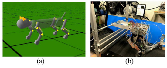
Figure 1.
Our previous studies. (a) A simulated quadruped model achieving uneven terrain walking; (b) a hind leg robot stepping on a speed variable treadmill.
In this study, we build a quadruped robot in which forelegs are added to the previous hind leg robot in Figure 1b, and control it with the four two-level CPGs with leg loading feedback coupled to produce a pace gait. Then, we demonstrate that the coupled two-level CPGs can achieve a stable pace running based on experiments at steady speeds on a treadmill.
It is reported in neurophysiology that changing connection strengths between the CPGs of the four legs can produce a variety of gaits [20,21]. Thus, to simply reproduce a pace gait for our quadruped robot in our present study, we first connected the ipsilateral CPGs and contralateral CPGs in strongly excited and inhibitory manners, respectively, without leg loading feedback to the CPGs. However, our robot failed in steady pace running because the oscillation of each leg swung by the dominant CPG was not able to synchronize with the roll body oscillation. The same results were observed even with leg loading feedback. Therefore, when we weakened the connection strengths, the coupling between the CPGs did not affect locomotion, and the quadruped robot steadily runs with a pronk, which is a gait in which all the four legs moved in phase.
Subsequently, when we added leg loading feedback to the CPG, resulting in the robot achieving a steady pace running at a constant speed. Since the body oscillated around the roll axis on the treadmill, a load applied to the ipsilateral pairs of legs toward which the body inclined increased. This allowed the stance phases of the ipsilateral legs to be simultaneously extended because of leg loading feedback, preventing the robot from falling toward the side. The robot alternated this adaptation on both sides, leading to a pace gait. In short, the cycles of each CPG and the roll body oscillation were autonomously synchronized through leg loading feedback. Interestingly, when we used leg loading feedback with the weakly coupled CPGs, the oscillation of each CPG was entrained in the roll body oscillation and autonomously converged to an arbitrary cycle, which was different from the original cycle of the CPG without leg loading feedback and suited the roll body oscillation. As a result, our robot safely paced by swinging each leg at a suitable cycle to suit the roll body oscillation without any joints around the roll axis or any instruction of the desired cycle. The present results demonstrated that the two-level CPG with leg loading feedback that we proposed can be used for steady pace running of a musculoskeletal quadruped robot as well as uneven terrain walking [15] and autonomous adaptation to external speed adaptation [17].
2. Quadruped Robot and Control Method
2.1. Quadruped Robot and Devices
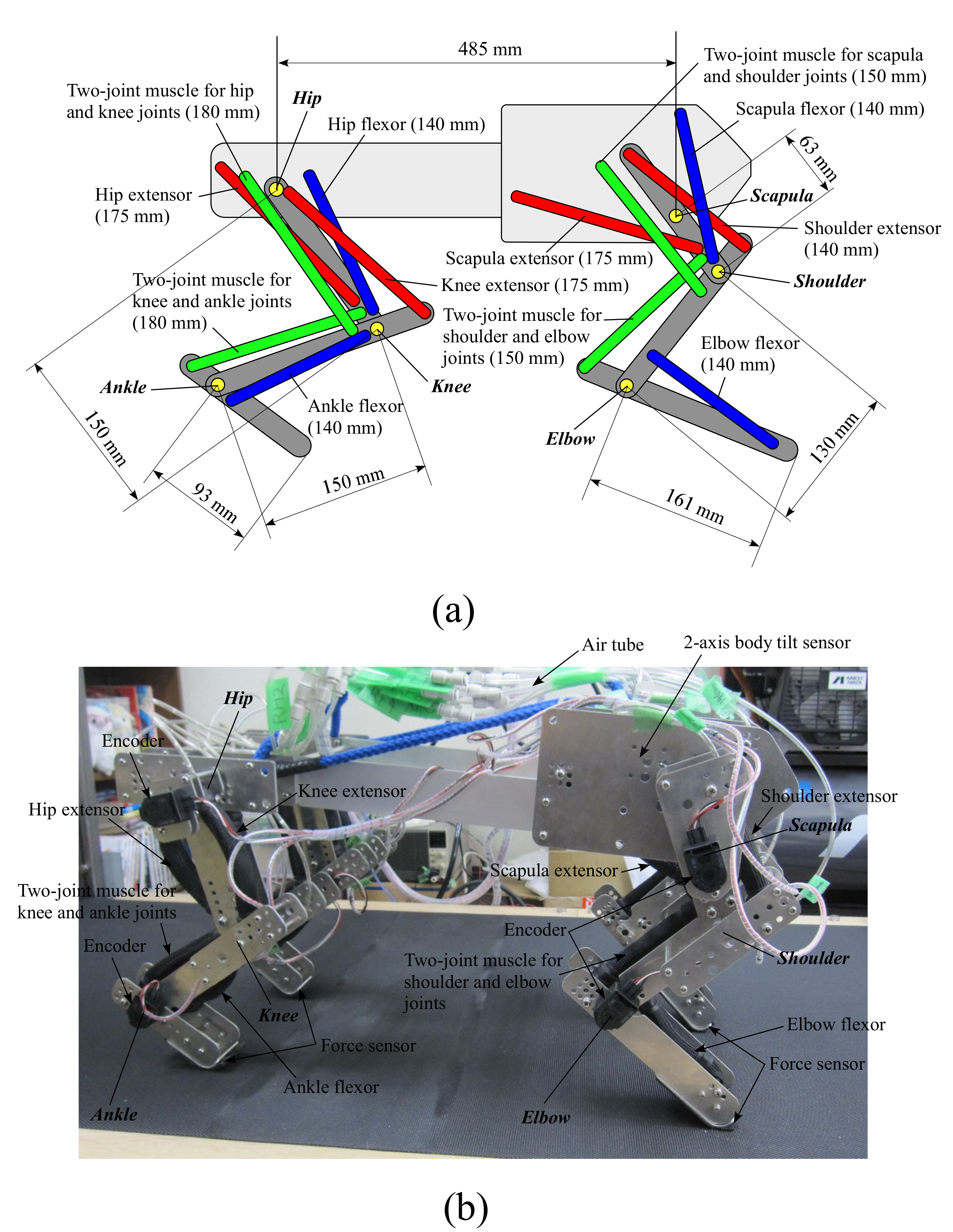
Figure 2a,b show an image of our quadruped robot and an overall diagram of the system, including the robot’s 3D design and external devices. The robot is 520 mm long and 280 mm wide. We detail the leg configuration in Section 2.2. Devices to drive and control the robot are externally placed, as shown in Figure 2b, and the robot is tethered to the external devices, which are listed in Table 1. The robot weighs 7.4 kg excluding external devices. The robot is controlled by the external robot control board with a sampling time of 2 ms.
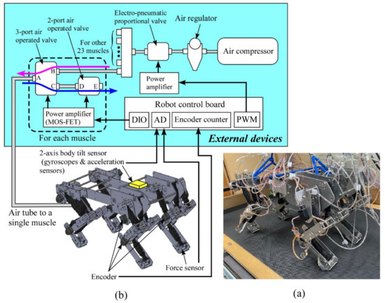
Figure 2.
(a) Picture of our quadruped, (b) overall diagram of our system.

Table 1.
List of external devices in Figure 2b.
Compressed air in all the artificial muscles is supplied by the air compressor in Figure 2b. The downstream air pressure from the air compressor is regulated to a constant pressure by the air regulator, and the electro-pneumatic proportional valve adjusts the maximum pressure according to a targeted locomotion speed, which is constant in this paper (i.e., 0.6 MPa for pacing at 7.5 m/s).
The part closed by the dashed square in Figure 2b shows a valve system to control the amount of air in a single pneumatic muscle actuator. The same system is required for the other 23 muscle actuators. To contract the muscle actuator, the three-port air-operated valve is set to HIGH (Path AB: open, AC: close), sending the compressed air to the corresponding muscle actuator, as shown by the magenta arrow. To relax the muscle, the three-port air-operated valve and the two-port air-operated valve are set to LOW (AB: close, AC: open) and HIGH (DE: open), respectively. Therefore, the compressed air trapped in the muscle is released outside, as shown by the blue arrow, and the muscle can relax. We detail the valve control based on a neural output in Section 2.3.2.
An attached encoder (HEDS-5500#A11; Broadcom Co., San Jose, CA, USA) measures the angle of each joint of the leg. The body tilt angles around the pitch and roll axes are calculated by integrating the value of the angular velocity detected by the corresponding gyroscopes (ENC-03R C/D; Murata Co., Kyoto, Japan), and their integration errors are modified by an acceleration sensor (CLX02LF3; Crossbow Co., Tokyo, Japan). The joints’ angles and body tilt angles are not used for control but only for data collection. We attach a force sensor (FlexiForce A201; Nitta Co., Osaka, Japan) on the foot sole of each leg as binary sensors to judge the leg’s footfall. Leg load is estimated from the extension of the two-joint muscle actuator for the shoulder and elbow joints or the knee and ankle joints of each leg, similar to the previous study [17]. This leg load is only needed for our controller to achieve a pace running as sensory information, but no sensory information is required to achieve a pronk running (see Section 3).
The robot locomotes on a handmade treadmill whose speed can be manually controlled according to the robot’s speed. Since our robot does not have any joints around the roll or yaw axis, it is difficult to correct the gradual turning of the robot on the treadmill. Therefore, the robot is slightly suspended during locomotion by an elastic string on each end of the front and rear such that the height of the torso is approximately 50 mm lower without the legs touching the ground than when the robot usually locomotes. This weak constraint cannot prevent our robot from falling, but can help the robot go almost straight on the treadmill. A human loosely holds a string in all experiments to avoid the possibility of a breakdown by falling over.
2.2. Leg Configuration
Figure 3a,b show the configurations of the fore and hind legs and the image of our quadruped robot, respectively. Each leg consists of three links connected by three rotary joints around the pitch axis. Each leg does not move around the roll or yaw axis. The torso is a rigid body. The robot has 12 joints in total. The length of each leg link is determined based on the biological findings [27,28]. An animal drives each leg joint by using various sides of muscles; however, each leg of our robot is driven by main six muscles for locomotion, including two two-joint muscles, based on a biological report [18] and related studies [29,30]. We use the McKibben-type pneumatic artificial muscle [16] manufactured by Kanda Tsushin Kogyo Co., Ltd. (Chiba, Japan) for all the muscles, which have a maximum tension of 800 N and a maximum shrinkage factor of 34% with a maximum diameter of 30 mm. Each muscle’s length when it is relaxed is written behind the name of the muscle in Figure 3a. The length and the connected positions are experimentally determined such that the force and the moving range of each joint can be satisfied.

Figure 3.
Configurations of the fore and hind legs (a), and an image of our quadruped robot (b).
2.3. Motion Generator
2.3.1. Two-Level CPG with Leg Loading Feedback
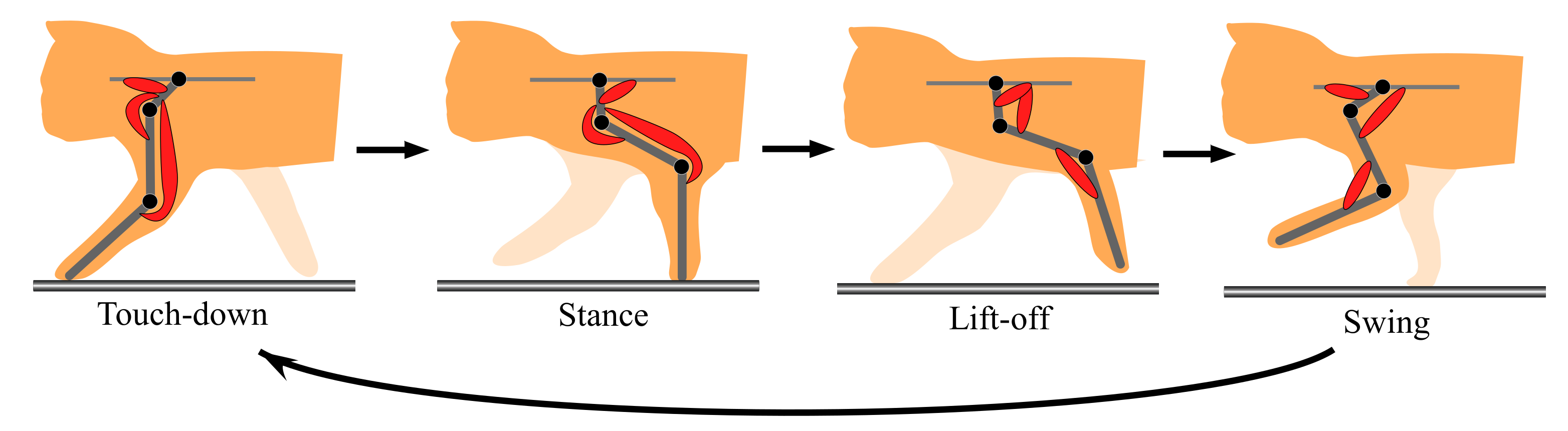
The aforementioned representative quadruped robots [7,12,13,14], which are driven by motors, have each simplified leg consisting of two links. Unlike these, to move a three-link leg along an animal-like leg trajectory, the robot has to drive each leg through the four sequential phases (touch-down, stance, lift-off, and swing) in one cycle, as shown in Figure 4. An animal synergistically activates a different set of muscles (the red muscles in Figure 4) in each of the four phases [18]. To realize the synergistic activation of muscles, we previously proposed two-level CPG, as shown in Figure 5 [15,17]. This was improved from the CPG proposed by Markin et al. [22,23]. We use the two-level CPG for our present running quadruped and drive its legs along the animal-like leg trajectory in Figure 4. The parameters are modified such that the quadruped robot can safely run. The CPG’s equations are shown in Appendix A, and we briefly explain the functions below.
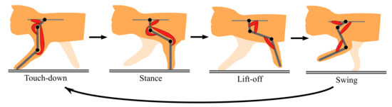
Figure 4.
Cycle of the four leg phases (touchdown, stance, liftoff, and swing).

Figure 5.
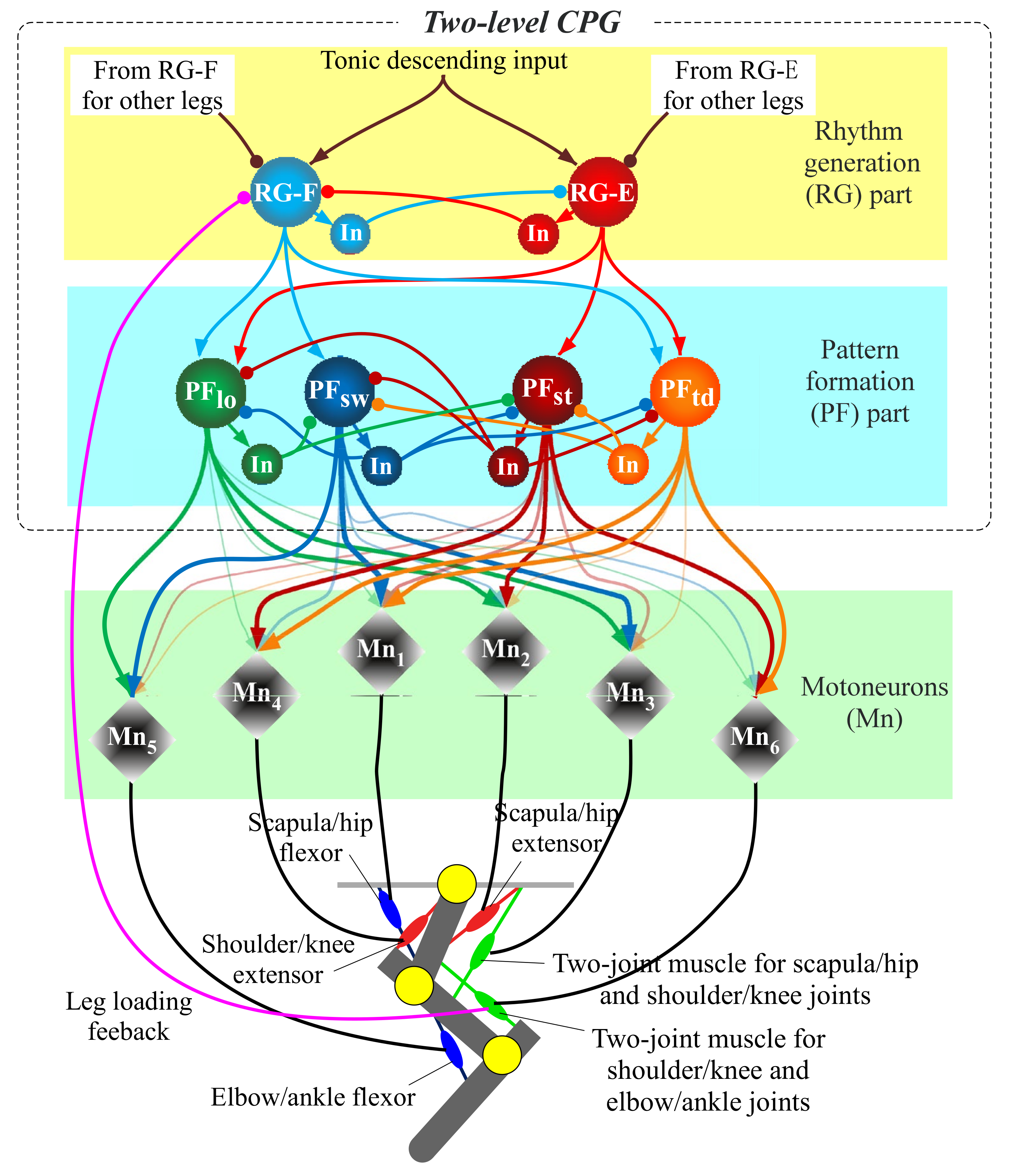
Diagram of the two-level central pattern generator (CPG) for each leg.
As shown in Figure 5, the CPG is divided into two parts, namely rhythm generation (RG) and pattern formation (PF). The RG part receives a constant tonic descending input when locomotion speed is constant and produces a basic locomotion rhythm for a single leg, which is generated by the mutual inhibitory connections between the extensor neuron (RG-E) and flexor neuron (RG-F). The PF part has the four PF neurons (PFtd, PFst, PFlf, and PFsw), which manage the four leg phases (touch-down, stance, lift-off, and swing) shown in Figure 4, respectively. While each PF neuron rhythmically bursts by receiving inputs from the RG neurons, the four PF neurons activate at different timings by mutually inhibiting each other. Eventually, the outputs from several of the PF neurons multiplied by different gains, which are shown by the thickness of the arrows from PF neurons to motoneurons, are integrated into each motoneuron to drive the corresponding muscle, as shown in Figure 5. The neural system activates the different sets of muscles in each of the four sequential phases, as shown in Figure 4. For example, in the forelegs, PFtd in Figure 5 is input with relatively strong gains to Mn1, Mn4, and Mn6 for the scapula flexor, shoulder extensor, and two-joint muscle for shoulder and elbow joints, respectively, which show the three red muscles in the case of touch-down in Figure 4. This leads the foreleg to the touch-down phase.
We apply leg loading feedback to the CPG, which is crucial to adjust the rhythm and support the body [25]. Specifically, leg load is inputted to the RG flexor neuron in an inhibitory manner, as shown in Figure 5, based on biological findings [25,31]. The feedback inhibits the activation of the RG flexor neuron in the stance phase, causing the extension of the stance duration. Similar to our previous hind leg robot [17], we estimate the leg load from tension applied to the two-joint muscle actuator for the shoulder/knee and elbow/ankle joints, which covers an elbow or ankle joint extensor, based on many locomotion experiments of decerebrate cats [25].
2.3.2. Control of the Pneumatic Muscle Actuators Based on the Motoneuron Output
Similar to the previous hind leg robot [17], we adjust the time ratio between the inputting and releasing times of air in each muscle every 50 ms with the ON/OFF solenoid valves, on the basis of the value of the neural output (Equation (A4) in Appendix A) from the corresponding motoneuron in Figure 5, and therefore control the air pressure in the muscle. Note that although it may be better to use a proportional solenoid valve to more precisely control the air pressure, it is too big to manage 24 muscles; therefore, we use the ON/OFF solenoid valves. Specifically, if (2/3 of the estimated maximum activity ), the compressed air is inputted for 33 ms (2/3 of 50 ms), and the trapped air is naturally released for 17 ms (1/3 of 50 ms). The sampling time of 50 ms is relatively long because the response time of the solenoid valves is slow; nevertheless, we demonstrated in our previous study with the same method [17] that the hind leg robot was capable of moving each leg along a realistic trajectory close to that of a cat. In addition, it is reported in biomechanics [32] that self-stabilization depending on muscular viscoelasticity is dominant and precise control is not very important while running. Thus, we conclude that our rough control system is acceptable for pace running.
2.3.3. CPG Network to Produce a Pace Gait
As shown in the RG part in Figure 5, a network consisting of the four coupled CPGs is completed when the RG neurons are connected to RG neurons in the CPGs of the other legs. Specifically, as shown in Figure 6, to reproduce a pace gait in our quadruped robot, we make the mutual inhibitory connections of the RG neurons between the contralateral legs with a weight of α, allowing the legs to swing out of phase, and the mutual excitatory connections of the RG neurons between the ipsilateral legs with a weight of β, allowing the legs to swing in phase.
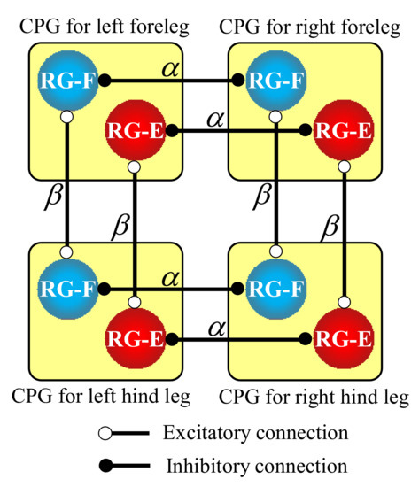
Figure 6.
Hard-wired CPG network between the four legs to produce a pace gait for our quadruped robot.
3. Running Experiments
We applied our two-level CPGs mutually coupled to produce a pace gait to our quadruped robot and verified if the robot can steadily run with pace at a constant speed on a treadmill. We experimentally determined all the parameters such that the quadruped robot can safely run, and they were fixed in all experiments.
We initially set the values of the weights α and β in Figure 6 to relatively large (e.g., ) to generate a robust pace gait. Therefore, the robot swung its four legs at a pace while being suspended in the air. However, when it was put on the treadmill, running became unstable because it was difficult to synchronize the legs’ oscillation forced by the strong CPG network with the roll body oscillation. That was the case even with leg loading feedback. Therefore, we eventually set smaller values of the weights (i.e., ).
The existence of leg loading feedback affected an emergence of a pace in experiments with the weak CPG network. The experimental results with and without leg loading feedback are shown in Section 3.1 and Section 3.2, respectively. All the parameter values used in Section 3.1 and Section 3.2 were the same with the exception of leg loading feedback.
3.1. Pronk Running without Leg Loading Feedback
In the beginning, we expected the robot without leg loading feedback to the CPG to pace because of the CPG network shown in Figure 6. However, the CPG network with small α and β values was not effective enough, and the robot ran with a pronk, in which all legs were in phase, at a constant speed of 1.0 m/s. The movie can be seen in the Supplementary Video S1, and the snapshots are shown in Figure 7. Figure 8 shows data in approximately three cycles, which include the outputs from the RG flexor (RG-F) and RG extensor (RG-E) neurons for the four legs, the joints’ angles of the left fore and hind legs (the origin and orientation are shown in the leg diagram), the footfalls for the four legs (thick lines represent the stance phases), and the body angles around the pitch and roll axes (positive when tilted forward and rightward).
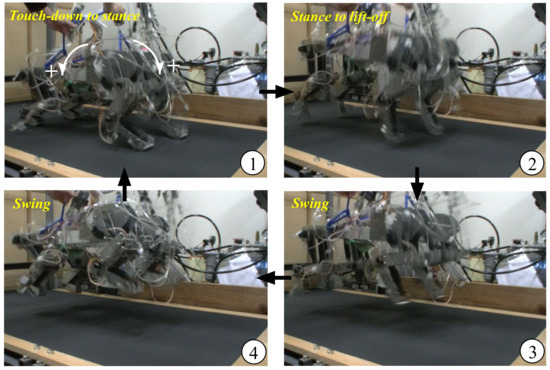
Figure 7.
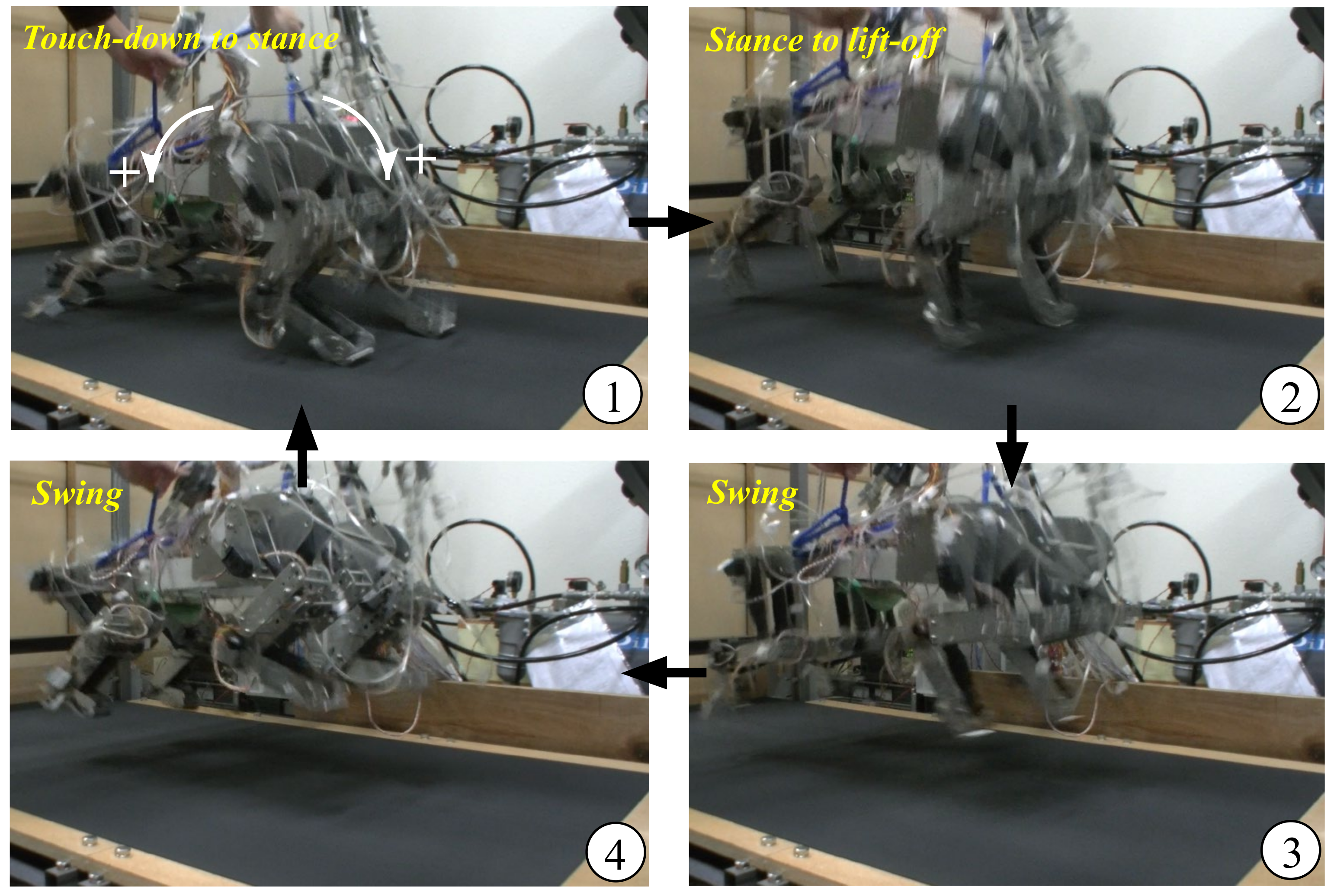
Snapshots of our quadruped robot running at a pace. ①–④ indicate the running sequence.
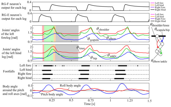
Figure 8.
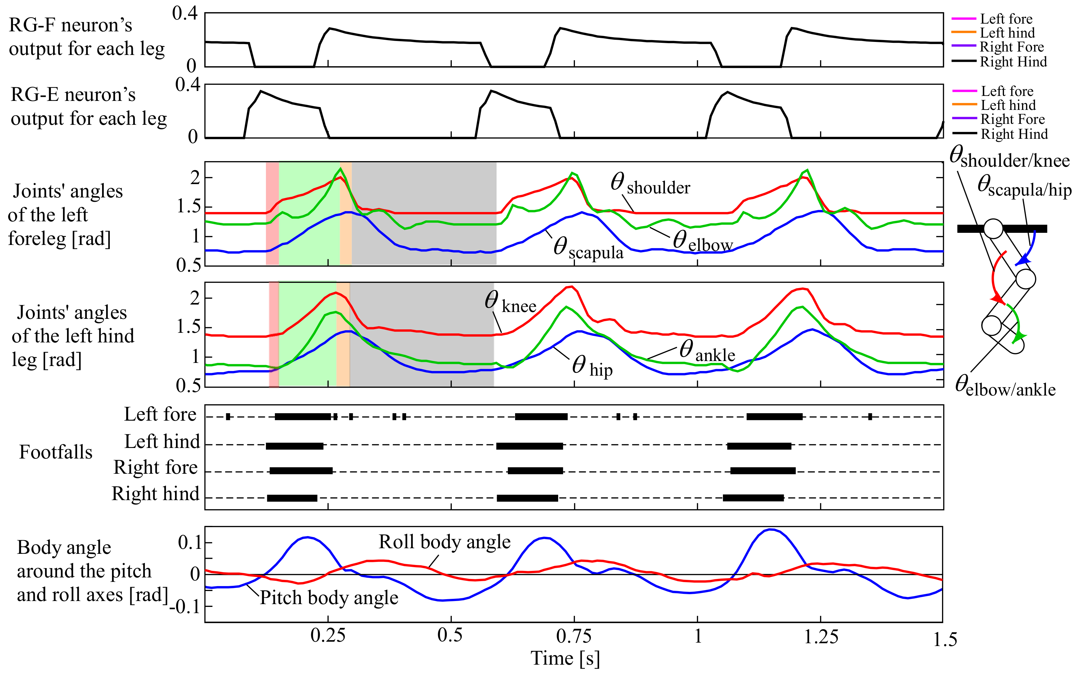
Experimental results of the pronk running of our quadruped robot, which include the outputs from the RG flexor (RG-F) and RG extensor (RG-E) neurons for the four legs, the joints’ angles of the left fore and hind legs (the origin and orientation are shown in the leg diagram), the footfalls for the four legs (thick lines represent the stance phases), and the body angles around the pitch and roll axes (positive when tilted forward and rightward, as shown by white arrows in ① of Figure 7).
In Figure 8, the outputs from RG-F and RG-E were exactly in phase between the four legs (i.e., the plots for the four legs exactly overlapped). As a result, the four legs similarly moved, as shown in the joints’ angles of the left fore and hind legs, and each leg performed the touch-down, stance, lift-off, and swing motions in order in the transparent red, green, orange, and grey periods, respectively. The footfalls were almost in phase between the four legs, and flight phases can be observed between the footfalls, resulting in a pace running, as shown in ③ and ④ of Figure 7. Note that the footfalls of the forelegs were somewhat delayed from those of the hind legs. This was caused because of the difference in the lengths between the fore and hind legs, leading to the deviations in timings of the feet touching and leaving the ground. This often happened in a pronk running in which the vertical movement of the body was large.
Because the robot did not have any sensory feedback from the CPG, the running cycle (approximately 0.47 s) was the same as the original cycle of the CPG.
3.2. Pace Running with Leg Loading Feedback
We conducted experiments when only adding leg loading feedback to the neural system in Section 3.1 in which all the parameters were the same except for leg loading feedback. The four legs were swung in phase, similar to pronking in Section 3.1, when the robot was suspended in the air at the beginning because leg loading feedback was inactive. However, when the robot was placed on the treadmill, it steadily ran at a pace at a constant speed of 0.75 m/s. The movie can be seen in the Supplementary Video S2, and the snapshots are shown in Figure 9. Figure 10 shows data in approximately three cycles, which include the outputs from the RG flexor (RG-F) and RG extensor (RG-E) neurons for the four legs, the four PF neurons (PFtd, PFst, PFlf, and PFsw), and the six motoneurons (Mn1–6) only for the left foreleg as a representative, the joints’ angles of the left fore and hind legs (the origin and orientation are shown in the leg diagram), the footfalls for the four legs (thick lines represent the stance phases), and the body angles around the pitch and roll axes (positive when tilted forward and rightward).

Figure 9.
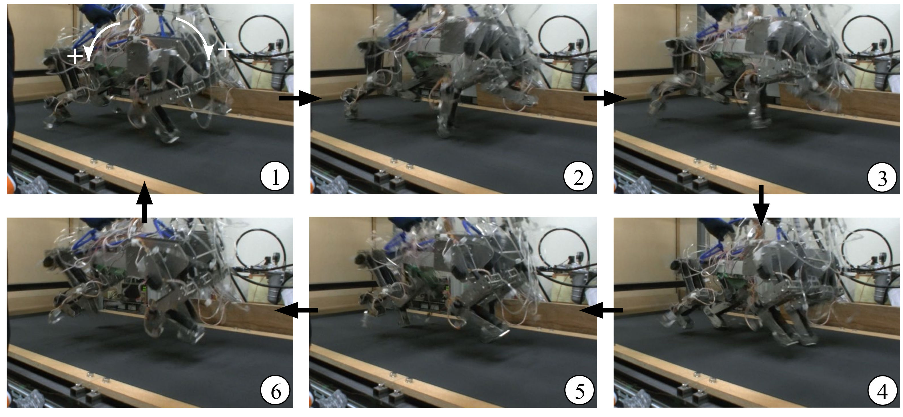
Snapshots of our quadruped robot running at a pace. ①–⑥ indicate the running sequence.

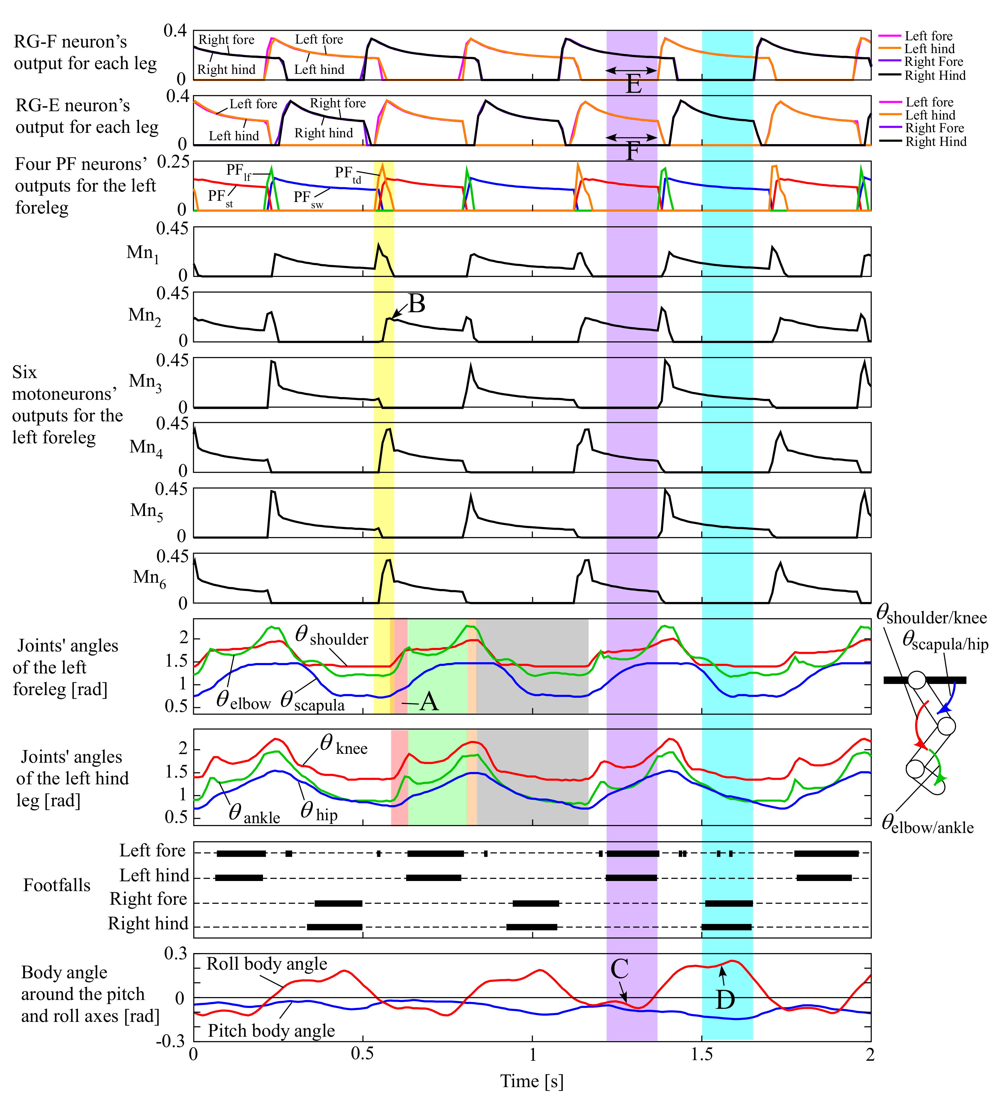
Figure 10.
Experimental results of the pace running of our quadruped robot, which include the outputs from the RG flexor (RG-F) and RG extensor (RG-E) neurons for the four legs, the four PF neurons (PFtd, PFst, PFlf, and PFsw), and the six motoneurons (Mn1–6) only for the left foreleg as a representative, the joints’ angles of the left fore and hind legs (the origin and orientation are shown in the leg diagram), the footfalls for the four legs (thick lines represent the stance phases), and the body angles around the pitch and roll axes (positive when tilted forward and rightward, as shown by white arrows in ① of Figure 9).
Similar to Figure 8, Figure 10 indicates that the left foreleg’s PF neurons for the four sequential phases periodically burst in the order PFtdPFstPFlfPFsw, such as in Figure 4. While each PF neuron was bursting, the motoneurons for the different sets of muscles shown in Figure 4 were simultaneously bursting. For example, when PFtd burst for the touch-down motion (a transparent yellow period in Figure 10), Mn1 for the scapula flexor, M4 for the shoulder extensor, and M6 for the two-joint muscle for shoulder and elbow joints burst strongly. Similar synergistic muscle activations happened for the other legs as well.
Consequently, the left foreleg was extended by increasing and for the touch-down motion in the transparent red period A of Figure 10 after a short time delay. Note that was expected to decrease as Mn1 (for the scapula flexor) strongly burst in the touch-down phase; however, Mn2 for the antagonist (the scapula extensor) burst in the subsequent stance phase (B in Figure 10), and the antagonistic bursting between Mn1 and Mn2 resulted in the increase in in period A. Similarly, , and of the left hind leg increased during the transparent red period for the touch-down motion. After the touch-down motion, each leg performed the stance, lift-off, and swing motions in order in the transparent green, orange, and grey periods, respectively.
Figure 10 also indicates that when the body tilted leftward (the roll body angle was negative as C), the two left legs were in the stance phases and the two right legs were in the swing phases ④ in Figure 9), and that when the body tilted rightward (the roll body angle was positive as D), the two right legs were in the stance phases and the two left legs were in the swing phases (① in Figure 9), and flight phases can be observed (③ and ⑥ in Figure 9), showing a steady pace running. This happened because of the leg loading feedback described in Section 2.3.1. When the body was tilted leftward and the two left legs were in the stance phases (a transparent purple period in Figure 10), the RG-F neurons for the two left legs were inhibited not to bursting, as shown in E, because of the inhibitory connection of leg loading feedback to the RG-F neurons. Conversely, the busting periods of the RG-E neurons for the two left legs were extended, as shown in F, because of the mutual inhibition between the RG-E and RG-F neurons. Therefore, while the body was tilted leftward, the two left stance legs supported the body. It can be observed in the transparent light blue period that the same adaptation happened when the two right legs were in the stance phases. Both side adaptations alternated according to the body oscillation; therefore, the leg and body oscillations were synchronized, making the robot capable of the steady pace running.
Based on the experimental results, generating stable pace running was caused by the autonomous adjustment of the cycle of the CPG through leg loading feedback. Leg loading feedback did not work when the robot was suspended in the air, and therefore, the cycle of each leg’s oscillation was 0.47 s, the same as that in pronking in Section 3.1. However, the cycle was autonomously adjusted to 0.58 s while the robot was steadily pacing on the treadmill. This was because the cycles of the roll body oscillation and each leg’s oscillation were synchronized through leg loading feedback. We did not need to command an appropriate running cycle, and the mutual physical interaction between the CPGs and the robot allowed the cycle to autonomously converge to an appropriate value, which caused a stable balance between the neural system and the body dynamics.
When the connection weights α and β between the four CPGs in Figure 6 were too large, the strong connections prevented the phase adjustment of each CPG by leg loading feedback. Consequently, the robot fell because it was not able to synchronize the leg oscillation with the roll body oscillation. When the gain of leg loading feedback ( in Equation (A3) in Appendix A) was excessively increased, the legs toward which the body inclined were in the stance phases too long, resulting in the robot failing in the locomotion.
4. Discussion on Improvements
In the future, we will have to improve the devices and method as follows to allow a quadruped robot driven by muscle actuators with our method to be used in practical missions, such as rescue activities, construction works, and human-assistive works.
A current limitation of our quadruped robot for practical use is the technology of muscle actuators. Muscle actuators that we can use to realize a quadrupedal running are currently limited because the actuator must be light, powerful, and durable, and it also has to quickly contract and relax for rapid movements. Currently available muscle actuators to meet the conditions are considered pneumatic actuators. Therefore, we use McKibben-type pneumatic artificial muscles, but they need an external heavy air compressor to supply enough compressed air to achieve a fast and long-term running. There are few chances for a robot with such bulky outer devices to be available in field locomotion. However, many other expected muscle actuators without any external power source have recently been developed [33,34] and will be available in the near future. We believe that our method can be used to drive the prospective muscle actuators for locomotion as well. A bioinspired quadruped robot with more practical muscle actuators will be operated over harsh field environments as long as its electronic devices are proof against water and dust.
Although a CPG with single feedback of leg load is applied in our current stage, the limited system can achieve a fairly stable pace of running. To perform stable walking and running over uneven terrain in real environments in the future, sensory feedback should be increased. Modification from brain signals may be further required. In the future, we will apply sensory feedback of a muscle length to the RG and PF neurons and the motoneurons. In addition, the existing leg load fed back to the RG neuron will be extended to the PF neurons and motoneurons. These ideas are based on findings in biology [25] and neuroscience [23]. These additional feedback signals are considered to work in disturbed situations especially when a robot locomotes over uneven terrain. For example, because of excitatory feedback of leg load to the PFst neuron in Figure 5, the leg may thrust the ground against the load while climbing a slope and steps. If the elbow flexor is extended by the tip of a foreleg being caught by a step in the swing phase, excitatory feedback of the length of the elbow flexor to the RG-F, PFlf, and PFsw neurons may induce the tip of the leg to quickly rise like a reflex, preventing the robot from falling forward. Our previous report [35] demonstrated that these additional reactions through sensory feedback were effective enough for walking over medium levels of uneven terrain, such as over small obstacles and on a gently inclined slope. The same should work for a pace running over uneven terrain. The inhibitory leg loading feedback to the RG-F neuron in our pace running robot allowed the stance phases on the side which the body inclined were extended, preventing our robot from falling toward the side. This feedback should be effective to a certain degree to ensure stability in the frontal plane over uneven terrain because our previous simulation study [15] demonstrated the effectiveness of the same method on walking over medium levels of uneven terrain. However, clearly, effective adaptations in the frontal plane will be needed to ensure stability over higher levels of uneven terrain that cause significantly falling sideways. Specifically, scapula and hip joints around the roll axis are required to avoid falling sideways. Since it is unrevealed in biology how to combine the roll joint’s control with the CPG’s activation, we consider that we will control the roll joint following desired trajectories created for the four sequential phases. Suggesting methods to create the desired trajectories is our future work.
5. Conclusions
Our goal is to design a neuromorphic locomotion controller for a prospective bioinspired quadruped robot driven by artificial muscle actuators. To this end, we previously proposed a two-level CPG with leg loading feedback and demonstrated that the simulated cat-like quadruped model could walk over uneven terrain and that the hind leg robot with pneumatic muscle actuators could autonomously adapt to an external speed change.
In the present research, we verified using the quadruped robot with the pneumatic muscle actuators if the proposed neural system can effectively generate a steady pace of running. As a result, the robot achieved a steady pace running with an appropriate cycle adjusted from each CPG’s original cycle. This was because each CPG’s oscillation autonomously synchronized with the roll body oscillation while pacing owing to the CPG network with weak connections and leg loading feedback to the corresponding CPG.
The following are the main contributions of this paper.
- (1)
- We demonstrated that our proposed neural system is beneficial as a controller for pace running using a quadruped robot driven by next-generation artificial muscle actuators in the future by achieving the steady pace running by our quadruped robot with realistic legs driven by artificial muscle actuators. This was difficult to achieve in the literature.
- (2)
- We demonstrated the advantage of leg loading feedback to the two-level CPG in stabilizing pace running by enabling steady pace running at a constant speed because of the autonomous synchronization between each leg’s oscillation and the roll body oscillation through leg loading feedback to the CPG without specifying its running cycle.
Supplementary Materials
The following are available online at https://www.mdpi.com/article/10.3390/app12094146/s1, Video S1: pronking, and Video S2: pacing.
Author Contributions
Conceptualization, Y.F.; Data curation, R.K.; Formal analysis, R.K., K.M. and M.Y.; Funding acquisition, Y.F.; Investigation, Y.F., R.K., K.M., M.Y. and M.T.; Methodology, Y.F.; Project administration, Y.F.; Software, R.K., K.M. and M.Y.; Supervision, Y.F., A.N.I., T.F. and Y.H.; Validation, Y.F.; Writing–original draft, Y.F.; Writing–review & editing, A.N.I., T.F. and Y.H. All authors have read and agreed to the published version of the manuscript.
Funding
This work was supported by the Japan Society for the Promotion of Science (Grant-in-Aid for Scientific Research (C), Grant Number: 18K11489).
Institutional Review Board Statement
Not applicable.
Informed Consent Statement
Not applicable.
Data Availability Statement
The data presented in this study are available on request from the corresponding author.
Acknowledgments
We would like to thank Yoshikazu Mori, Naoji Shiroma, Kousuke Inoue, and Keisuke Yagi for their valuable comments and advice. We would like to thank our colleges for their contribution to the results.
Conflicts of Interest
The authors declare no conflict of interest.
Appendix A
Design of Two-Level CPG Model
We describe our previously proposed two-level CPG model in this section. For more detailed information, refer to our previous studies [16,18].
In Figure 5, the membrane potential of the main neurons in the RG and PF parts and the six motoneurons is expressed as
and that of the interneurons is expressed as
where is a neuronal capacitance, is the average membrane voltage of the neuron, , , and are persistent sodium, potassium rectifier, and leakage currents, respectively. and are excitatory and inhibitory synaptic currents. The currents are expressed as
where and are the maximal conductances of the ionic channels and the reversal potentials. and are the gains of the excitatory and inhibitory synaptic input from neuron to neuron , and is the gain of the tonic descending signal to neuron . is a feedback gain. represents the mutual inhibitory connections of the RG neurons between the contralateral legs, as shown in Figure 5. represents the mutual excitatory connections of the RG neurons between the ipsilateral legs. The variables , , and are described in our previous paper [15]. The average population activity from neuron is expressed by a sigmoid function as
where is a half-activation voltage, is a sigmoid gain, and is the threshold of each neuron.
Leg loading feedback is input to only for the RG-F neuron through a sigmoid function as
where is the value of the force sensor attached to the tip of each leg to detect the footfall (if , the leg is in the stance phase), is leg load, which is estimated from the length of the two-joint muscle actuator for the shoulder and elbow joints or the knee and ankle joints, and is a sigmoid gain.
References
- Muybridge, E. Animal in Motion; Dover Publications: New York, NY, USA, 1957. [Google Scholar]
- Fukui, T.; Matsukawa, S.; Habu, Y.; Fukuoka, Y. Gait Transition from Pacing by a Quadrupedal Simulated Model and Robot with Phase Modulation by Vestibular Feedback. Robotics 2022, 11, 3. [Google Scholar] [CrossRef]
- Kimura, H.; Shimoyama, I.; Miura, H. Dynamics in the dynamic walk of a quadruped robot. Adv. Robot. 1989, 4, 283–301. [Google Scholar] [CrossRef] [Green Version]
- Raibert, M.H. Trotting, pacing and bounding by a quadruped robot. J. Biomech. 1990, 23, 79–81. [Google Scholar] [CrossRef]
- Sano, A.; Furusho, J. Realization of dynamic quadruped locomotion in pace gait by controlling walking cycle. In Experimental Robotics II; Springer: Berlin/Heidelberg, Germany, 2005; pp. 491–502. [Google Scholar]
- Homby, G.S.; Takamura, S.; Yamamoto, T.; Fujita, M. Autonomous evolution of dynamic gaits with two quadruped robots. IEEE Trans. Robot. 2005, 21, 402–410. [Google Scholar]
- Kim, D.; Di Carlo, J.; Katz, B.; Bledt, G.; Kim, S. Highly Dynamic Quadruped Locomotion via Whole-Body Impulse Control and Model Predictive Control. arXiv 2019, arXiv:1909.06586. [Google Scholar]
- Saputra, A.A.; Takesue, N.; Wada, K.; Ijspeert, A.J.; Kubota, N. AQuRo: A Cat-like Adaptive Quadruped Robot With Novel Bio-Inspired Capabilities. Front. Robot. AI 2021, 8, 35. [Google Scholar] [CrossRef]
- Rutishauser, S.; Sprowitz, A.; Righetti, L.; Ijspeert, A.J. Passive compliant quadruped robot using Central Pattern Generators for locomotion control. In Proceedings of the 2nd IEEE RAS & EMBS International Conference on Biomedical Robotics and Biomechatronics, Scottsdale, AZ, USA, 19–22 October 2008. [Google Scholar]
- Srinivas, T.; Madhusudhan, A.K.K.; Manohar, L.; Pushpagiri, N.M.S.; Ramanathan, K.C.; Janardhanan, M.; Nielsen, I. Valkyrie. Design and Development of Gaits for Quadruped Robot Using Particle Swarm Optimization. Appl. Sci. 2021, 11, 7458. [Google Scholar] [CrossRef]
- Hildebrand, M. The adaptive significance of tetrapod gait selection. Am. Zool. 1980, 20, 255–267. [Google Scholar] [CrossRef]
- Boston Dynamics, Spot. Available online: http://www.bostondynamics.com/ (accessed on 2 March 2022).
- Cruz Ulloa, C.; Prieto Sánchez, G.; Barrientos, A.; Del Cerro, J. Autonomous Thermal Vision Robotic System for Victims Recognition in Search and Rescue Missions. Sensors 2021, 21, 7346. [Google Scholar] [CrossRef]
- Hutter, M.; Gehring, C.; Lauber, A.; Gunther, F.; Bellicoso, C.D.; Tsounis, V.; Fankhauser, P.; Diethelm, R.; Bachmann, S.; Bloesch, M.; et al. ANYmal—Toward legged robots for harsh environments. Adv. Robot. 2017, 31, 918–931. [Google Scholar] [CrossRef]
- Habu, Y.; Uta, K.; Fukuoka, Y. Three-dimensional walking of a simulated muscle-driven quadruped robot with neuromorphic two-level central pattern generators. Int. J. Adv. Robot. Syst. 2021, 16, 1729881419885288. [Google Scholar] [CrossRef]
- Klute, G.K.; Czerniecki, J.M.; Hannaford, B. McKibben artificial muscles: Pneumatic actuators with biomechanical intelligence. Proceedings of IEEE/ASME International Conference on Advanced Intelligent Mechatronics, Atlanta, GA, USA, 19–23 September 1999. [Google Scholar]
- Fukuoka, Y.; Habu, Y.; Inoue, K.; Ogura, S.; Mori, Y. Autonomous speed adaptation by a muscle-driven hind leg robot modeled on a cat without intervention from brain. Int. J. Adv. Robot. Syst. 2021, 18, 17298814211044936. [Google Scholar] [CrossRef]
- Krouchev, N.; Kalaska, J.F.; Drew, T. Sequential activation of muscle synergies during locomotion in the intact cat as revealed by cluster analysis and direct decomposition. J. Neurophysiol. 2006, 96, 1991–2010. [Google Scholar] [CrossRef] [PubMed] [Green Version]
- Reighard, J.E.; Jennings, H.S. Anatomy of the Cat; H. Holt and Company: New York, NY, USA, 1901. [Google Scholar]
- Grillner, S. Handbook of Physiology; John Wiley & Sons: Hoboken, NJ, USA, 1981; pp. 1179–1236. [Google Scholar]
- Golubitsky, M.; Stewart, I.; Buono, P.L.; Collins, J.J. Symmetry in locomotor central pattern generators and animal gaits. Nature 1999, 401, 693–695. [Google Scholar] [CrossRef] [PubMed]
- Markin, S.N.; Klishko, A.N.; Shevtsova, N.A.; Lemay, M.A.; Prilutsky, B.I.; Rybak, I.A. Afferent control of locomotor CPG: Insights from a simple neuromechanical model. Ann. N. Y. Acad. Sci. 2010, 1198, 21–34. [Google Scholar] [CrossRef]
- Markin, S.N.; Klishko, A.N.; Shevtsova, N.A.; Lemay, M.A.; Prilutsky, B.I.; Rybak, I.A. A neuromechanical model of spinal control of locomotion. In Neuromechanical Modeling of Posture and Locomotion; Springer: New York, NY, USA, 2016; pp. 21–65. [Google Scholar]
- Pearson, K. Role of sensory feedback in the control of stance duration in walking cats. Brain Res. Rev. 2008, 57, 222–227. [Google Scholar] [CrossRef]
- Duysens, J.; Clarac, F.; Cruse, H. Load regulating mechanisms in gait and posture: Comparative aspects. Physiol. Rev. 2000, 80, 83–133. [Google Scholar] [CrossRef] [Green Version]
- Orlovsky, G.N.; Severin, F.V.; Shik, M.L. Locomotion induced by stimulation of the mesencephalon. Dokl. Akad. Nauk. SSSR 1966, 169, 1223–1226. [Google Scholar]
- English, A.W. An electromyographic analysis of forelimb muscles during overground stepping in the cat. J. Exp. Biol. 1987, 76, 105–122. [Google Scholar] [CrossRef]
- Goslow, G.E., Jr.; Reinking, R.M.; Stuart, D.G. The cat step cycle: Hind limb joint angles and muscle lengths during unrestrained locomotion. J. Morphol. 1973, 141, 1–41. [Google Scholar] [CrossRef]
- Ekeberg, O.; Pearson, K. Computer simulation of stepping in the hind legs of the cat: An examination of mechanisms regulating the stance-to-swing transition. J. Neurophysiol. 2005, 94, 4256–4268. [Google Scholar] [CrossRef] [PubMed] [Green Version]
- Maufroy, C.; Kimura, H.; Takase, K. Towards a general neural controller for quadrupedal locomotion. Neural Netw. 2008, 21, 667–681. [Google Scholar] [CrossRef] [PubMed]
- Pearson, K.; Ekeberg, Ö.; Büschges, A. Assessing sensory function in locomotor systems using neuro-mechanical simulations. Trends Neurosci. 2006, 29, 625–631. [Google Scholar] [CrossRef]
- Kubow, T.; Full, R. The role of the mechanical system in control: A hypothesis of self-stabilization in hexapedal runners. Philos. Trans. R Soc. Lond. B Biol. Sci. 1999, 354, 849–861. [Google Scholar] [CrossRef] [Green Version]
- Acome, E.; Mitchell, S.K.; Morrissey, T.G.; Emmett, M.B.; Benjamin, C.; King, M.; Radakovitz, M.; Keplinger, C. Hydraulically Amplified Self-Healing Electrostatic Actuators with Muscle-like Performance. Science 2018, 359, 61–65. [Google Scholar] [CrossRef] [PubMed] [Green Version]
- Qiu, Y.; Zhang, E.; Plamthottam, R.; Pei, Q. Dielectric Elastomer Artificial Muscle: Materials Innovations and Device Explorations. Acc. Chem. Res. 2019, 52, 316–325. [Google Scholar] [CrossRef] [PubMed]
- Kimura, H.; Fukuoka, Y.; Cohen, A.H. Adaptive dynamic walking of a quadruped robot on natural ground based on bio-logical concepts. Int. J. Robot. Res. 2007, 26, 475–490. [Google Scholar] [CrossRef]


Publisher’s Note: MDPI stays neutral with regard to jurisdictional claims in published maps and institutional affiliations. |
© 2022 by the authors. Licensee MDPI, Basel, Switzerland. This article is an open access article distributed under the terms and conditions of the Creative Commons Attribution (CC BY) license (https://creativecommons.org/licenses/by/4.0/).