
Design and Experiments of a Compact Self-Assembling Mobile Modular Robot with Joint Actuation and Onboard Visual-Based Perception


Abstract
:1. Introduction
- •
- A novel parallel mechanism-based joint actuation and onboard vision-based perception system are presented to enhance docking, self-assembly, and actuation for the joints’ DoFs. The parallel mechanism can make the robot thinner and enlarge the workspace by longer providing links, which is different from revolute actuators. Onboard vision-based perception improves sensing information and enables the robot to sense autonomously, rather than using external cameras.
- •
- The docking methods for a multi-stage docking procedure based on relative positioning in different ranges are proposed for self-assembly.
- •
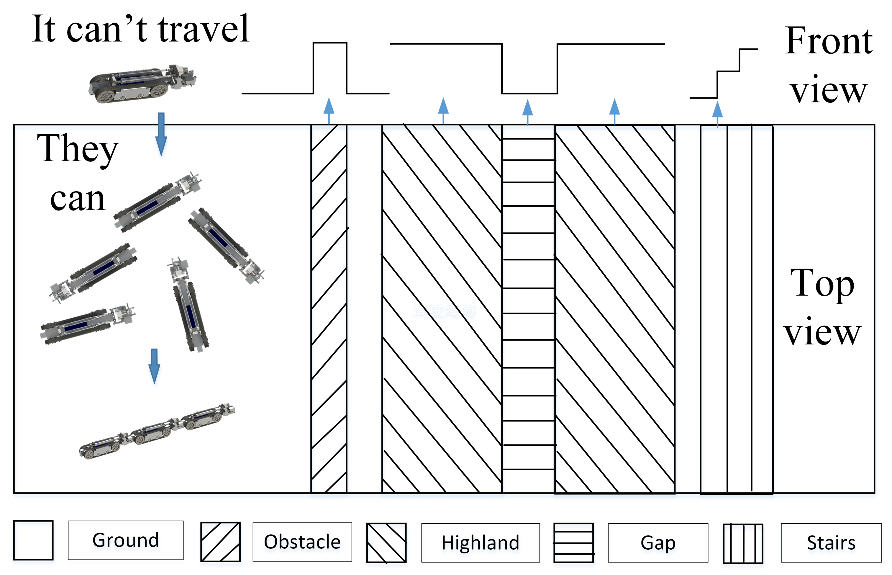
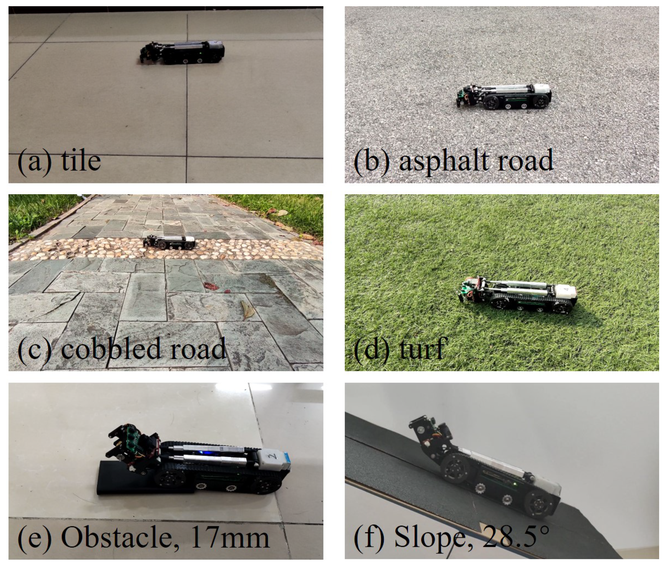
- A compact modular robot is designed to make the robot system robust and capable, taking a track-based chassis, as well as mechanically connecting, sensing, actuating and computing performance, into consideration. The modular robot is capable of traveling over different surfaces and the assembled composite entity uses chained wheels and joints to overcome obstacles. Experimental evaluations on module performance, self-assembly, and overall locomotion were performed, showing that the design was implemented well.
2. Design
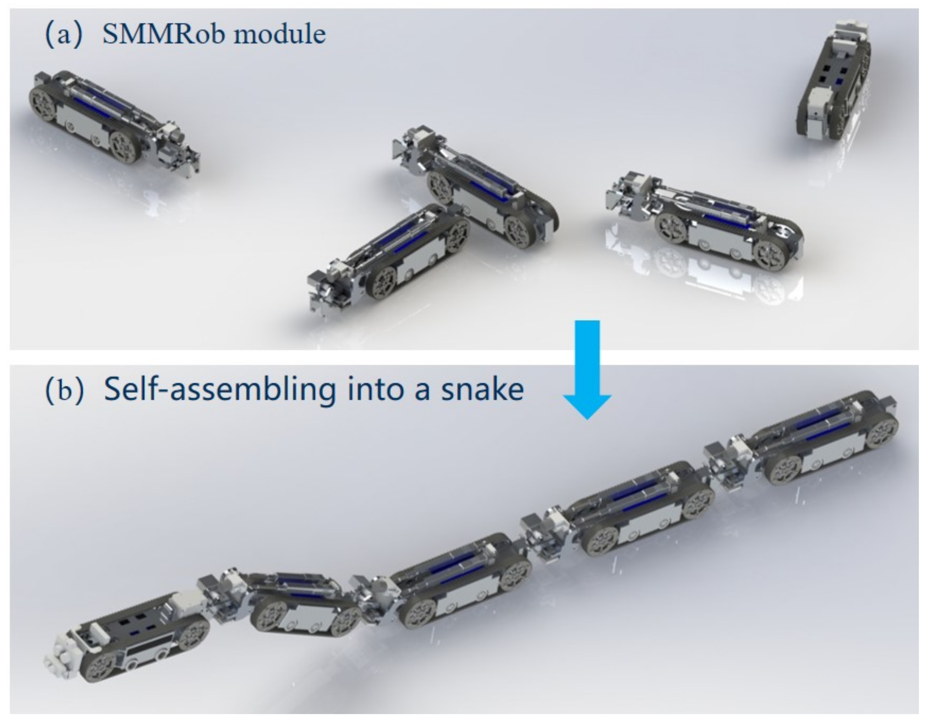
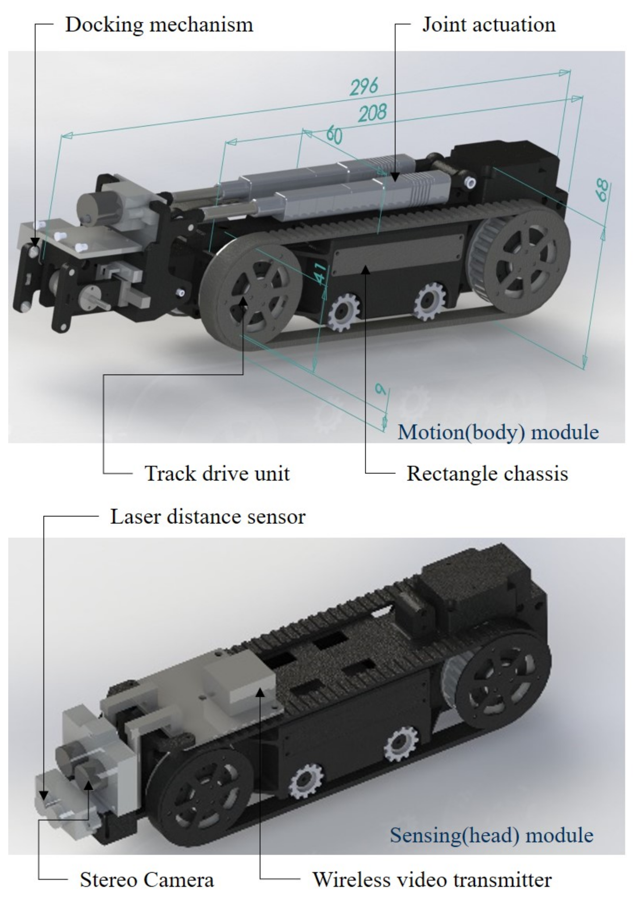
2.1. Overview of SMMRob System and Module
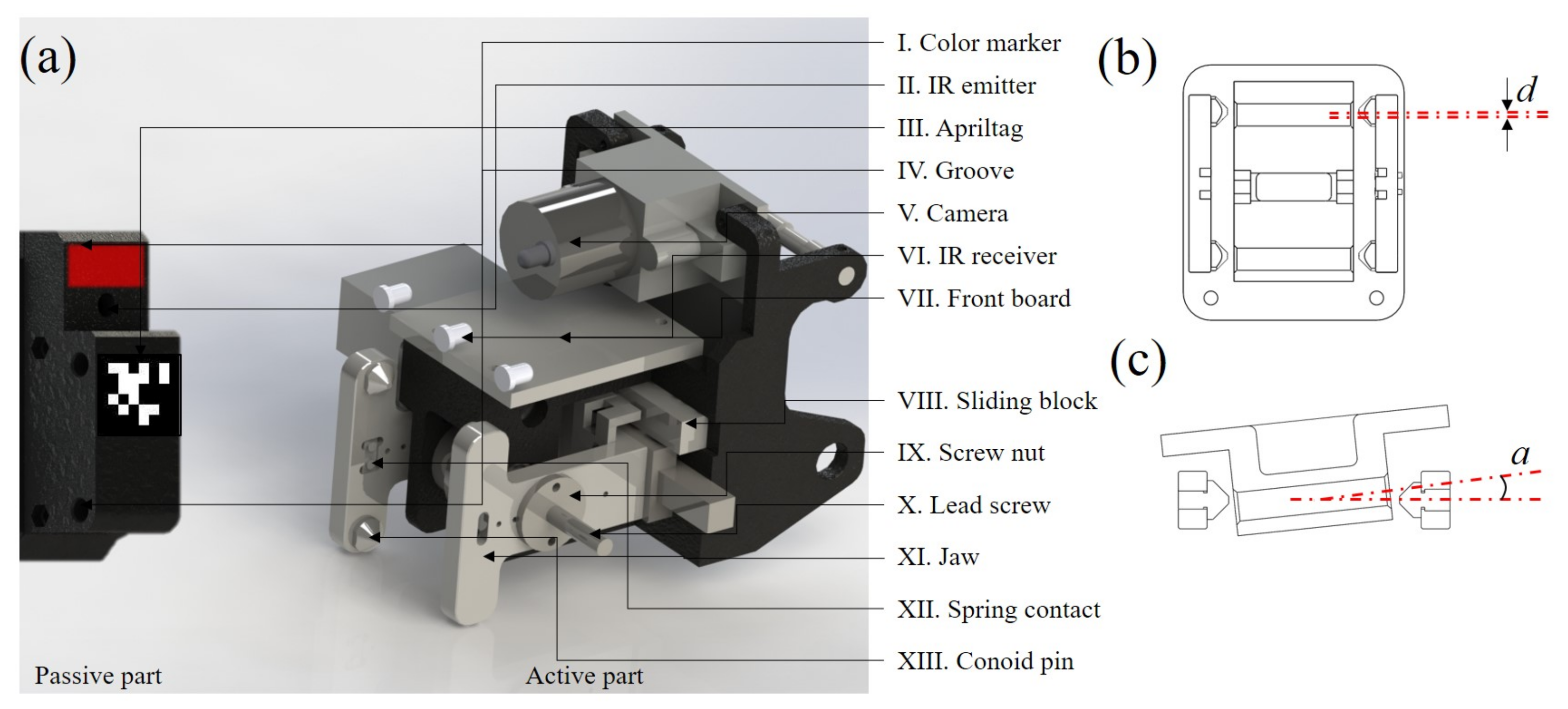
2.2. Docking Mechanism
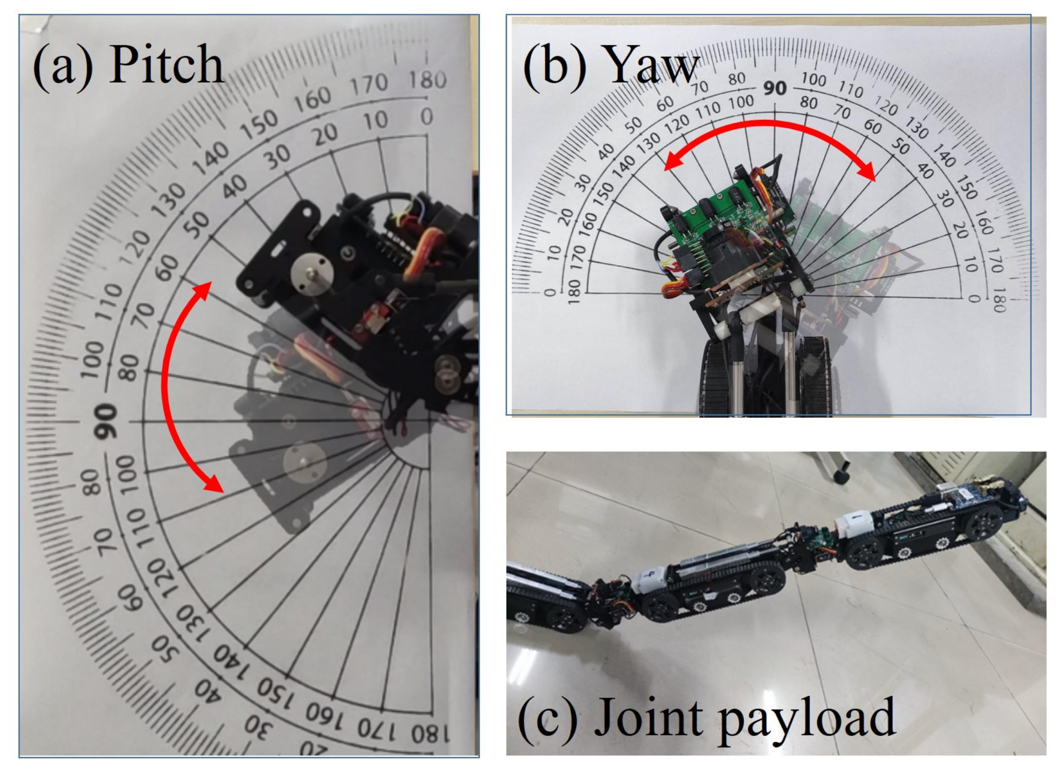
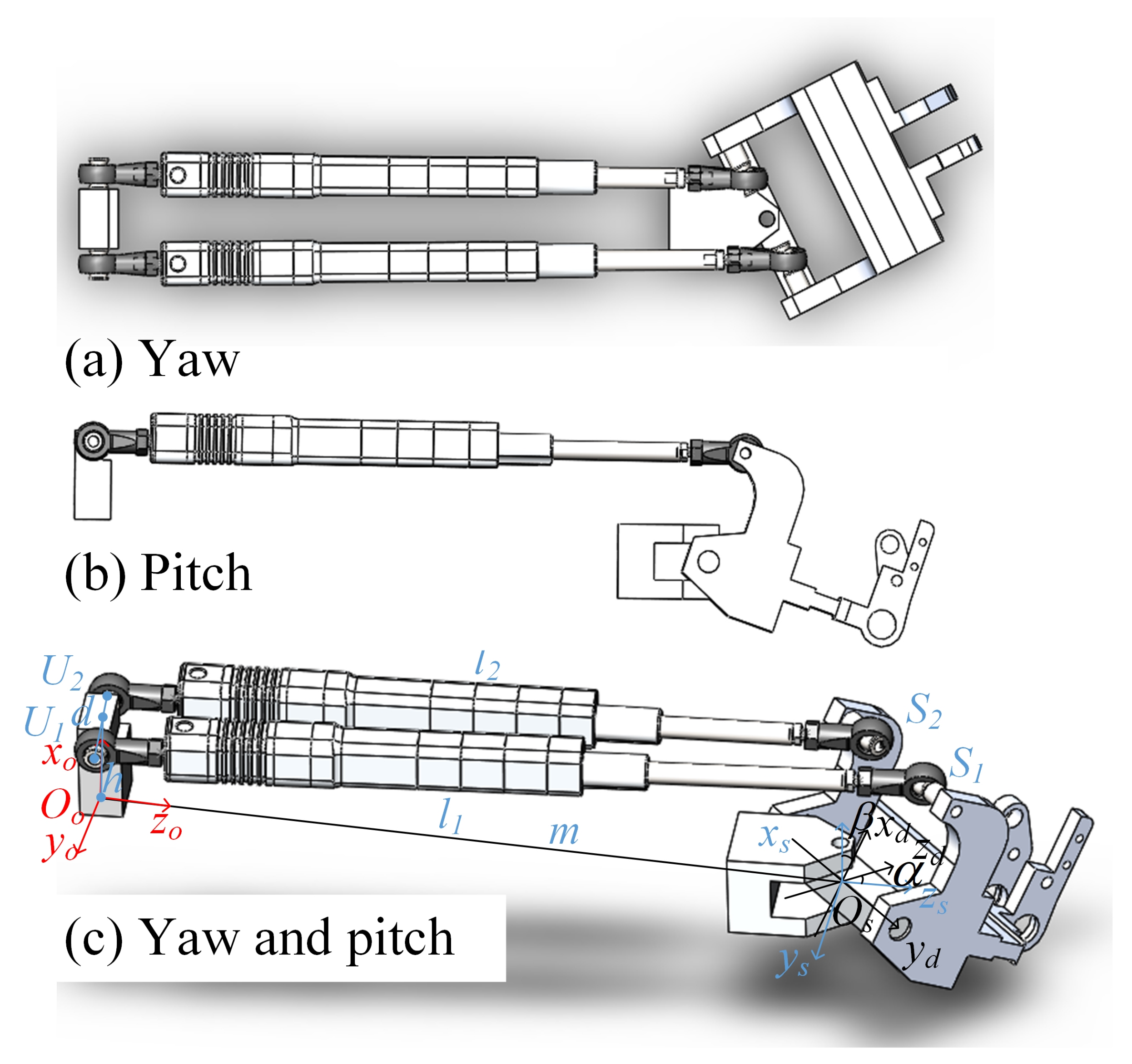
2.3. Joint Actuation
2.4. Sensing, Control, Communication, and Localization
2.4.1. Sensing
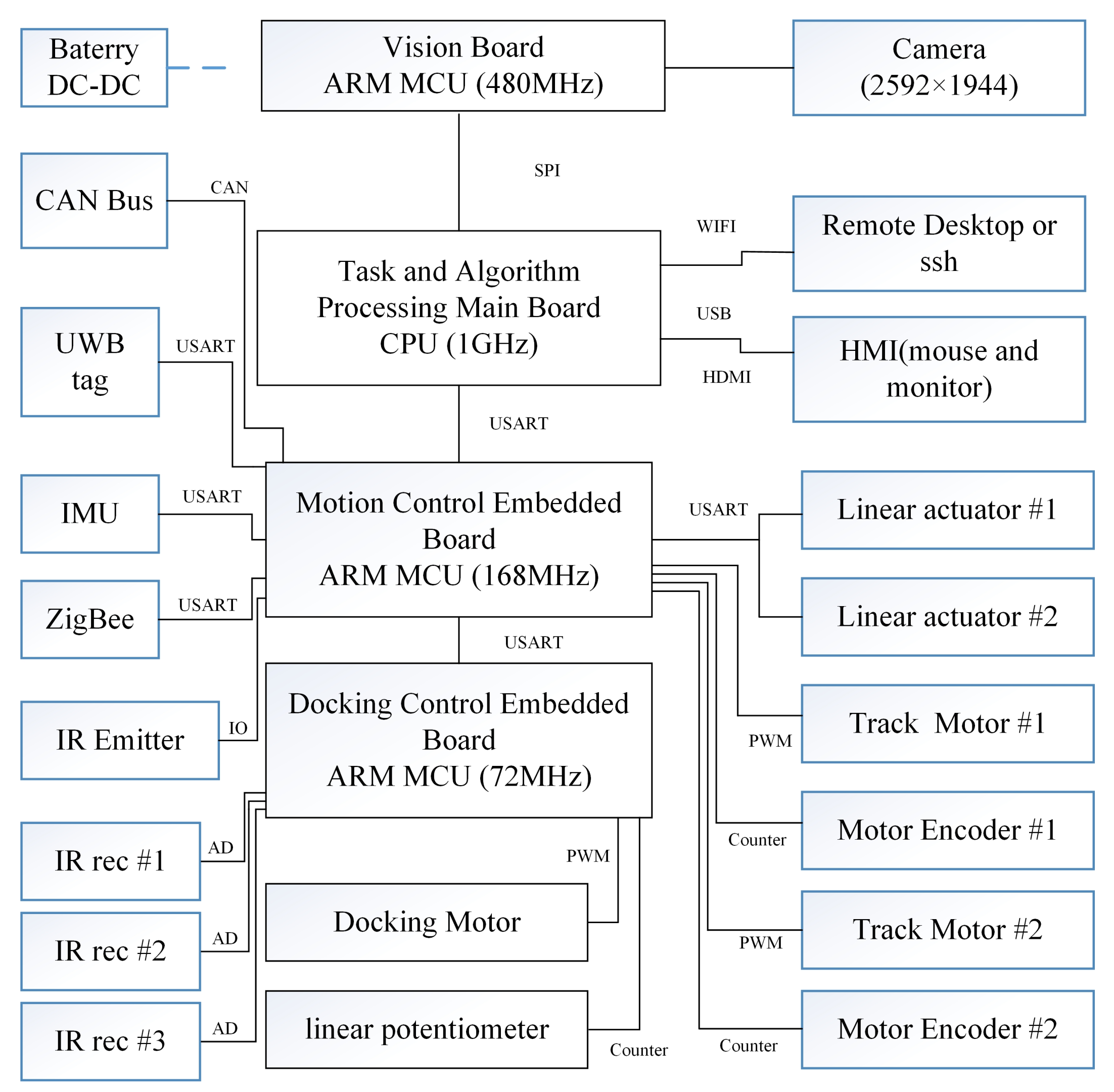
2.4.2. Control
2.4.3. Communication
2.4.4. Localization
2.4.5. Software and Protocol
3. Control Methods
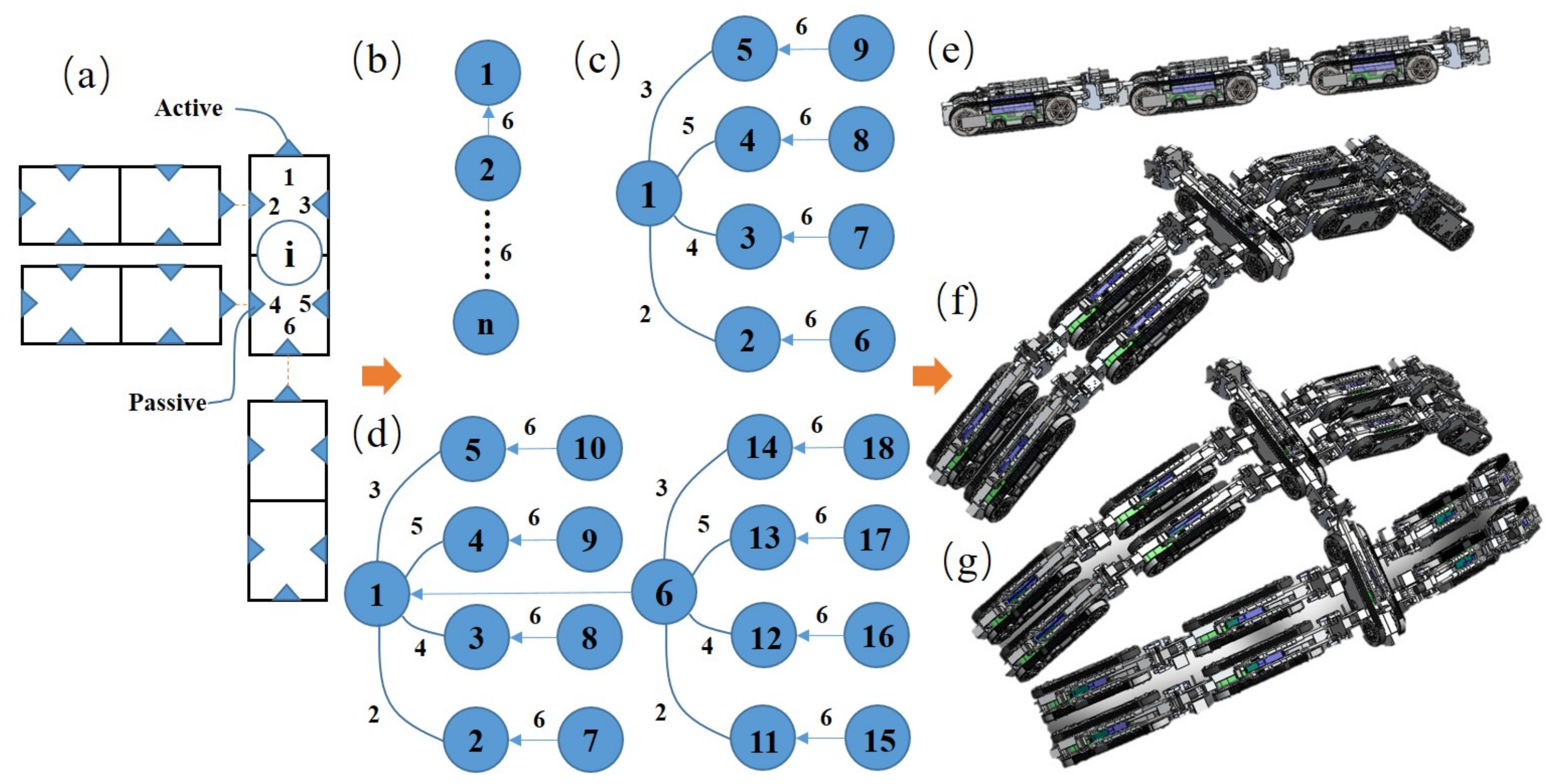
3.1. Self-Assembly Configuration Planning Sequence
3.2. Model of SMMRob
3.2.1. Mobile Kinematics
3.2.2. Kinematics of Joint Mechanism
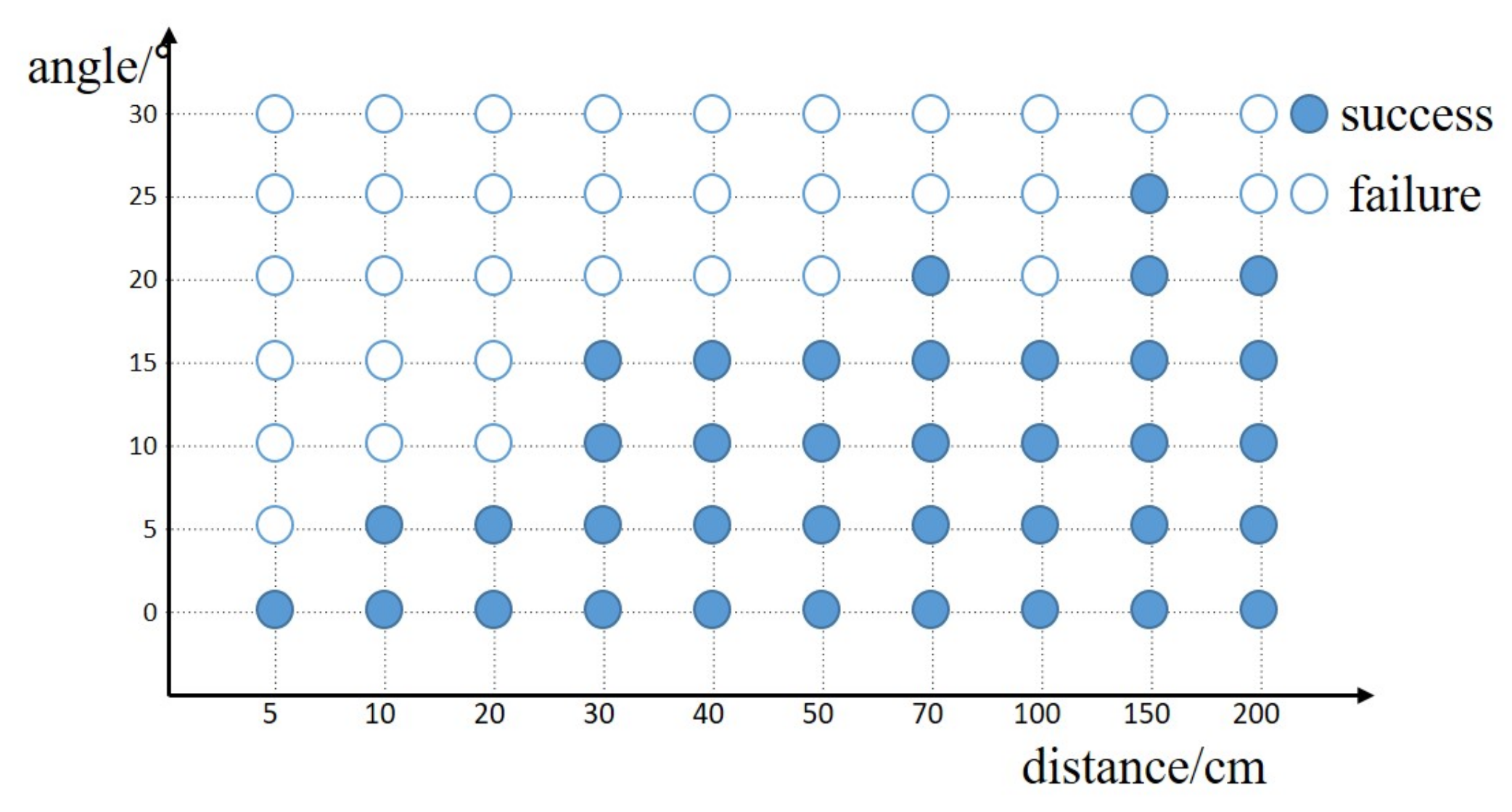
3.3. Docking Method
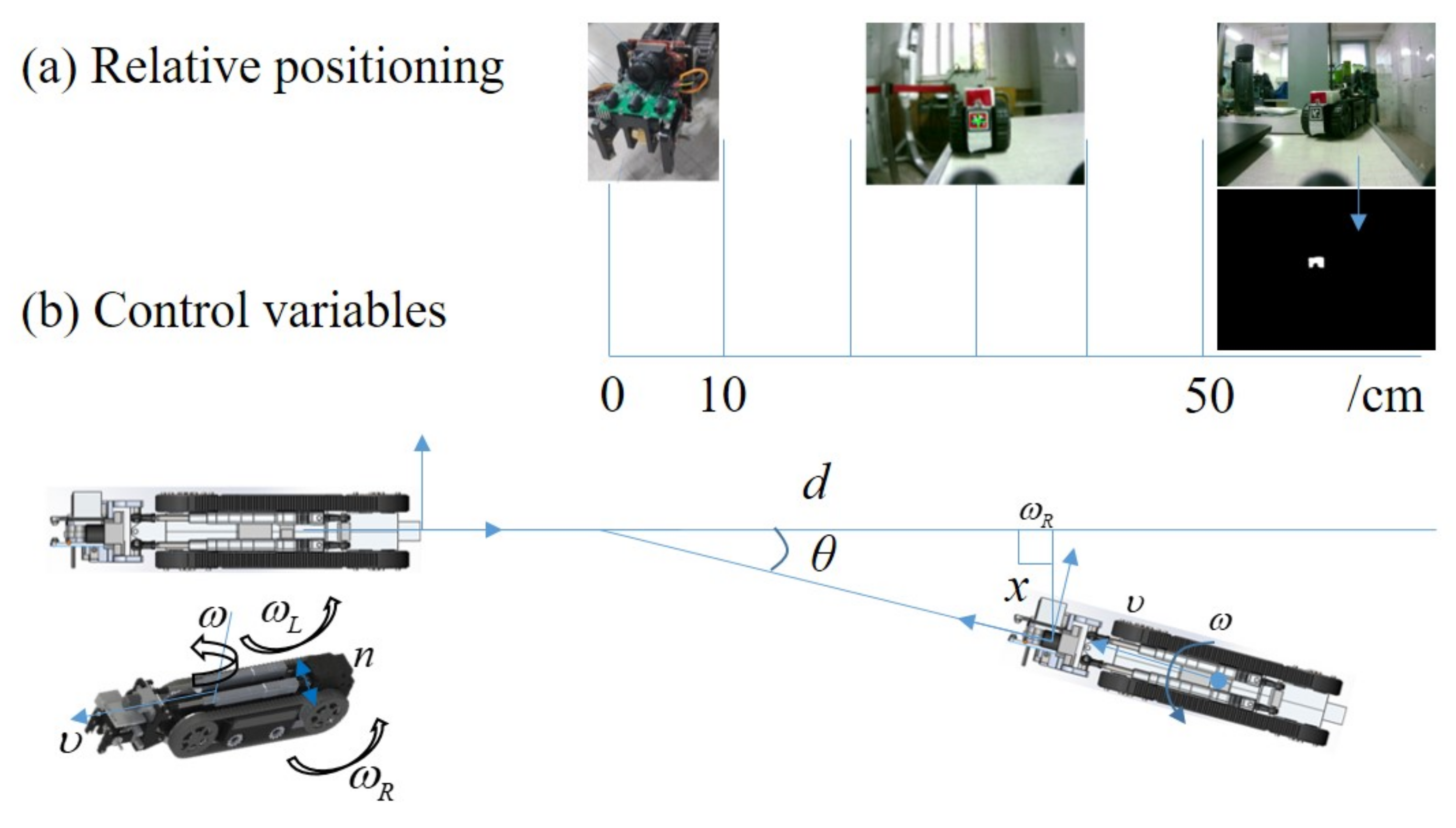
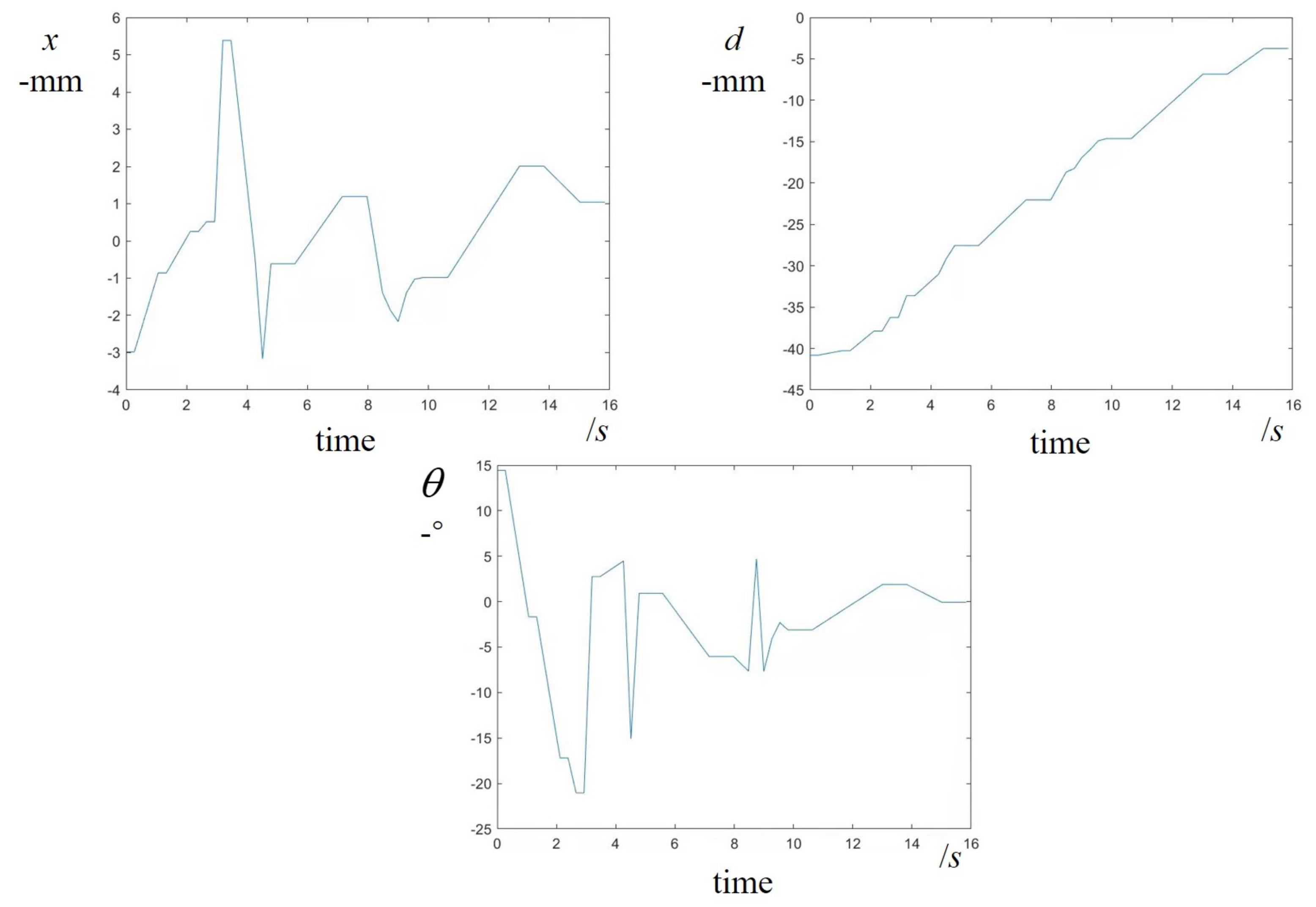
3.3.1. Relative Positioning
- •
- x is the lateral distance.
- •
- d is the longitudinal displacement.
- •
- is the difference in the heading angle of two robots.
- •
- In the far range ( cm), the color marker of the passive docking panel is recognized by the camera. It has a wide detection field and an easy-to-process algorithm. The color marker indicates that this may be a robot without an ID. The lightness, green value, and red values in LAB color space are used for target segmentation and the markers’ geometric center in pixel units is the target position. The binary image with a white block indicating the color marker is shown in Figure 9a.
- •
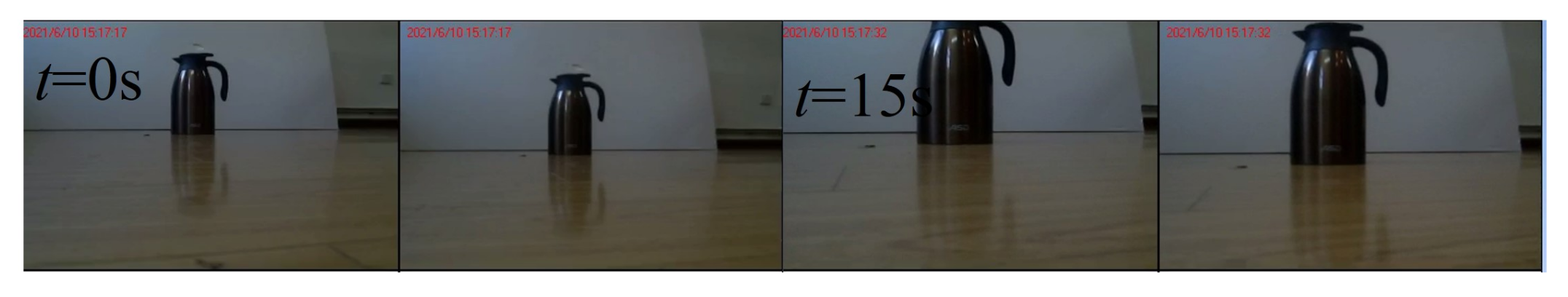
- In the middle range ( 50 cm 10 cm), the encoded marker (Apriltag) is used to guide docking. The visual processing board can generate the coordinate and bounding-box information (see Figure 9b) of the Apriltag and transfer them to . Although the recognition range is minimized, the precise coordinate is given and the robot is identified by its ID.
- •
- In the near range ( cm), the color and Apriltag marker pass beyond the field of view of the camera. The infrared sensors are used to guide the robot based on signal strength, expressed as d, and the weighted average of the lateral distances of three infrared receivers, expressed as .
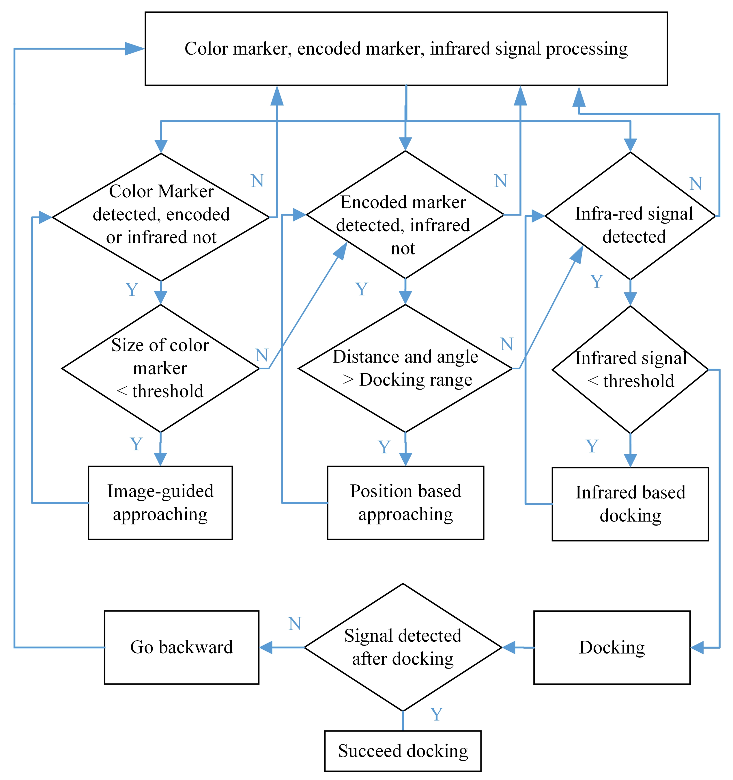
3.3.2. Docking Controller
- •
- Image-guided approaching controller. In the far range, the docking controller is based on an image-guided approaching scheme. and are controlled and and in image coordinates with pixel units are scaled up to minimize and . The PID controller is used, expressed as f. When the size of the color marker is larger than the threshold or the Apriltag or an infrared signal is detected, it switches to the next corresponding subroutine.
- •
- Position-based approaching controller. In the middle range, the coordinates including the position and yaw angle can be calculated in time. is scaled up to control to align the heading and is inversely proportional to and directly proportional to . f is a PI controller. If the distance between two robots is less than a certain value, the later robot moves backward. When the later robot moves into the infrared range, the infrared-based subroutine is called.
- •
- Infrared-based docking controller. In the near range, is scaled up to control to minimize the distance and is adjusted to control until the infrared signal reaches a threshold. f is a PI controller.
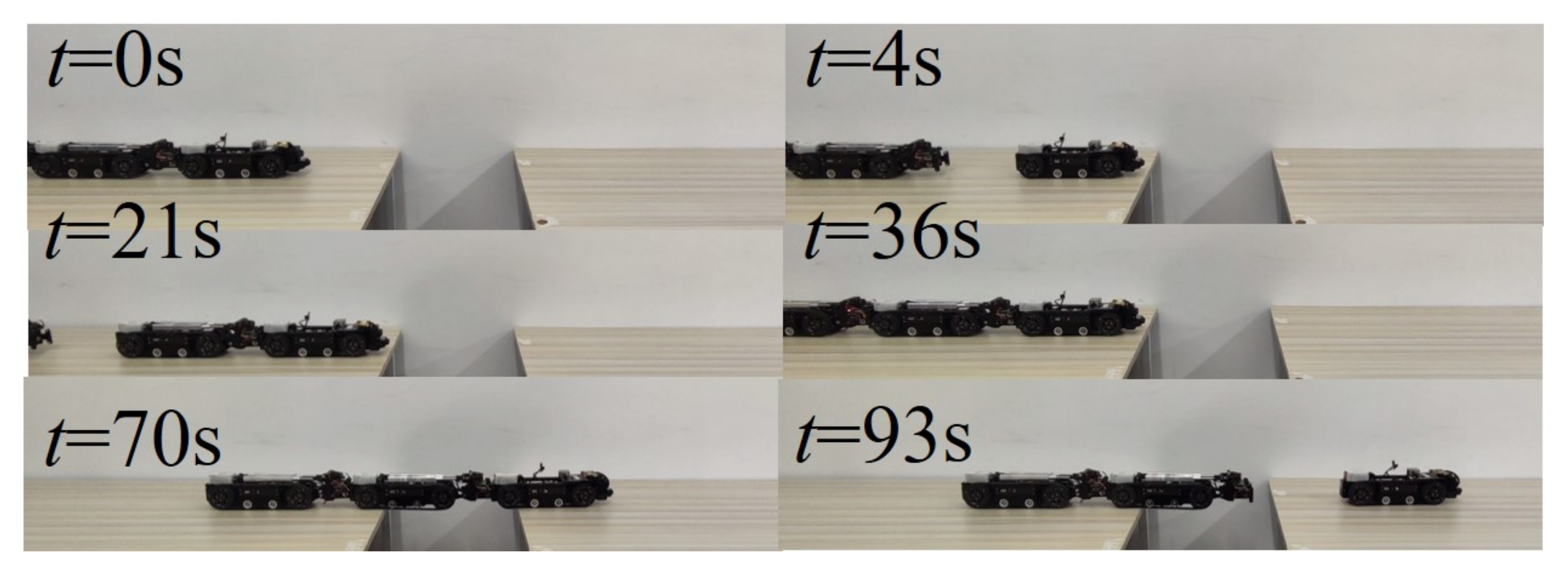
3.4. Obstacle Crossing Method
4. Experiments and Discussion
4.1. Module Experiments
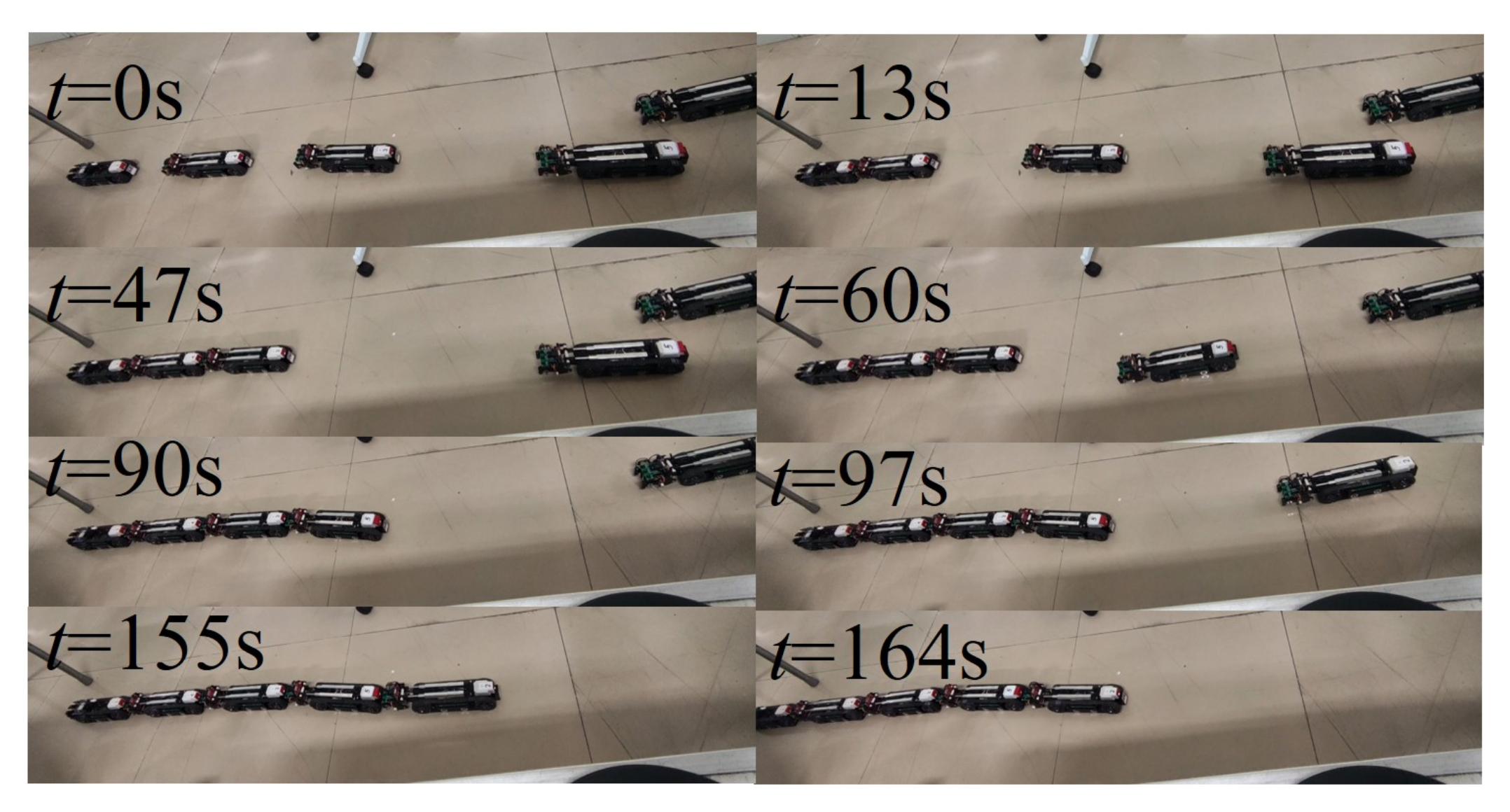
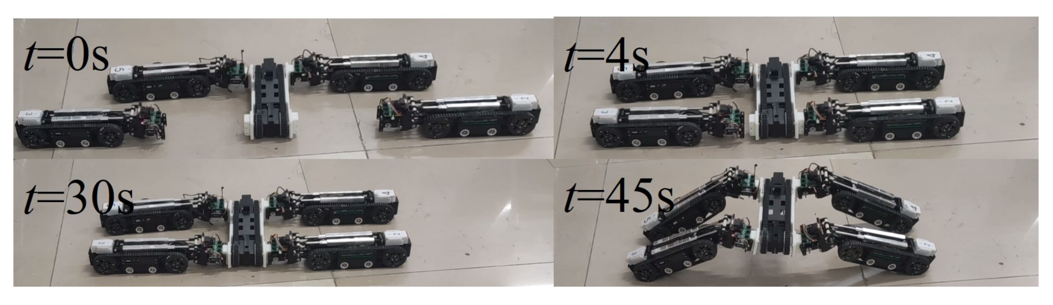
4.2. Self-Assembling Experiments
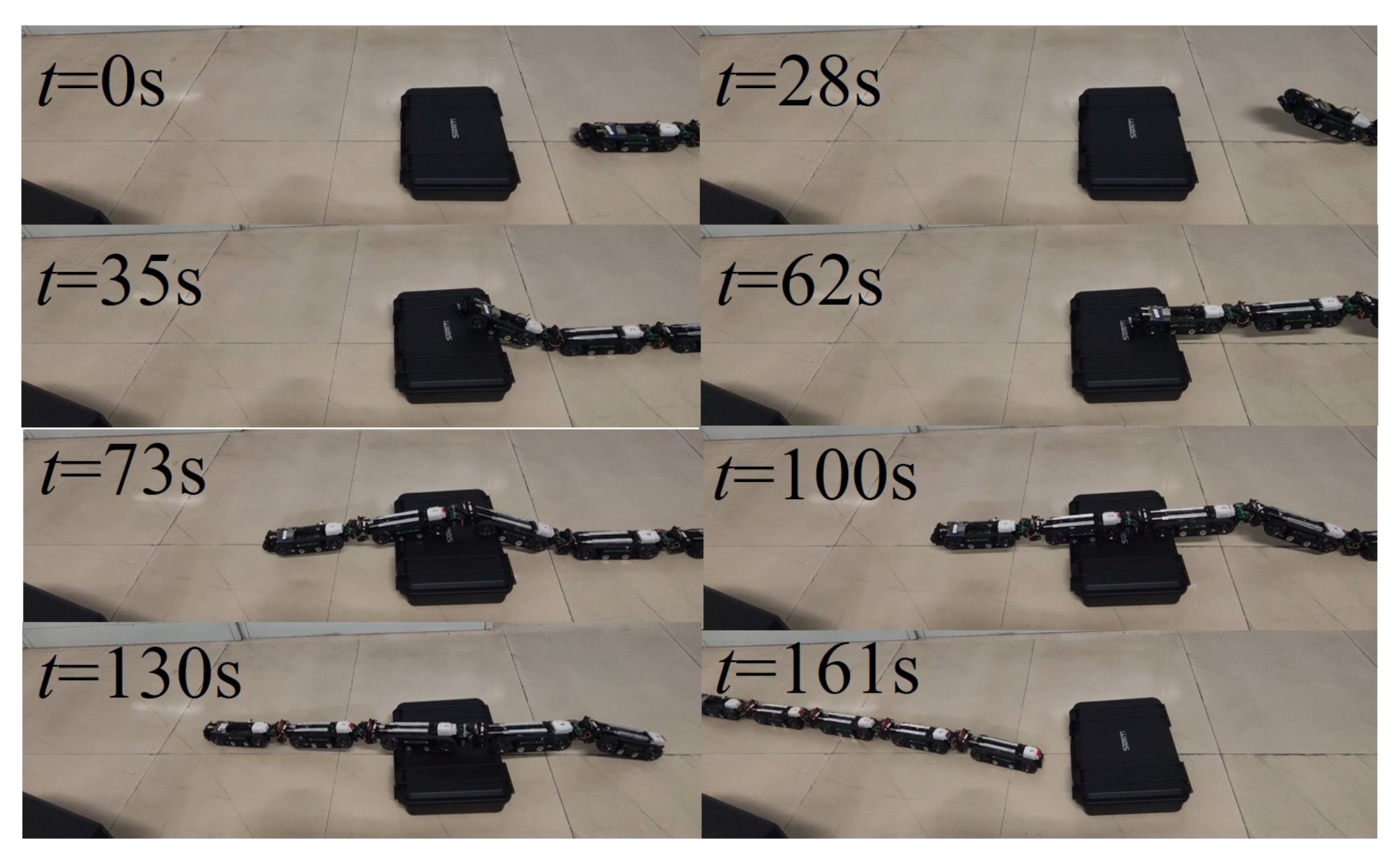
4.3. Systematic Experiments
5. Conclusions
Supplementary Materials
Author Contributions
Funding
Institutional Review Board Statement
Informed Consent Statement
Data Availability Statement
Acknowledgments
Conflicts of Interest
References
- Petersen, K.H.; Napp, N.; Stuart-Smith, R.; Rus, D.; Kovac, M. A review of collective robotic construction. Sci. Robot. 2019, 4, eaau8479. [Google Scholar] [CrossRef] [PubMed]
- Reid, C.R.; Lutz, M.J.; Powell, S.; Kao, A.B.; Couzin, I.D.; Garnier, S. Army ants dynamically adjust living bridges in response to a costbenefit trade-off. Proc. Natl. Acad. Sci. USA 2015, 112, 15113–15118. [Google Scholar] [CrossRef] [PubMed] [Green Version]
- Yim, M.; Shen, W.M.; Salemi, B.; Rus, D.; Moll, M.; Lipson, H.; Klavins, E.; Chirikjian, G.S. Modular self-reconfigurable robot systems [Grand challenges of robotics]. IEEE Robot. Autom. Mag. 2007, 14, 43–52. [Google Scholar] [CrossRef]
- Chirikjian, G. Kinematics of a metamorphic robotic system. In Proceedings of the 1994 IEEE International Conference on Robotics and Automation, San Diego, CA, USA, 8–13 May 1994; IEEE Computer Society Press: Washington, DC, USA, 1994; Volume 2, pp. 449–455. [Google Scholar] [CrossRef]
- Kirby, B.T.; Aksak, B.; Campbell, J.D.; Hoburg, J.F.; Mowry, T.C.; Pillai, P.; Goldstein, S.C. A modular robotic system using magnetic force effectors. In Proceedings of the IEEE International Conference on Intelligent Robots and Systems, San Diego, CA, USA, 29 October–2 November 2007; pp. 2787–2793. [Google Scholar] [CrossRef] [Green Version]
- Hauser, S.; Mutlu, M.; Ijspeert, A.J. Kubits: Solid-State Self-Reconfiguration with Programmable Magnets. IEEE Robot. Autom. Lett. 2020, 5, 6443–6450. [Google Scholar] [CrossRef]
- Romanishin, J.W.; Mamish, J.; Rus, D. Decentralized Control for 3D M-Blocks for Path Following, Line Formation, and Light Gradient Aggregation. In Proceedings of the 2019 IEEE/RSJ International Conference on Intelligent Robots and Systems (IROS), Macau, China, 3–8 November 2019; pp. 4862–4868. [Google Scholar] [CrossRef]
- Sastra, J.; Chitta, S.; Yim, M. Dynamic rolling for a modular loop robot. Int. J. Rob. Res. 2009, 28, 758–773. [Google Scholar] [CrossRef]
- Sproewitz, A.; Moeckel, R.; Maye, J.; Ijspeert, A.J. Learning to move in modular robots using central pattern generators and online optimization. Int. J. Rob. Res. 2008, 27, 423–443. [Google Scholar] [CrossRef] [Green Version]
- Murata, S.; Kakomura, K.; Kurokawa, H. Toward a scalable modular robotic system. IEEE Robot. Autom. Mag. 2007, 14, 56–63. [Google Scholar] [CrossRef]
- Hauser, S.; Mutlu, M.; Léziart, P.A.; Khodr, H.; Bernardino, A.; Ijspeert, A.J. Roombots extended: Challenges in the next generation of self-reconfigurable modular robots and their application in adaptive and assistive furniture. Rob. Auton. Syst. 2020, 127, 103467. [Google Scholar] [CrossRef]
- O’Grady, R.; Groß, R.; Christensen, A.L.; Dorigo, M. Self-assembly strategies in a group of autonomous mobile robots. Auton. Robots 2010, 28, 439–455. [Google Scholar] [CrossRef]
- Dorigo, M.; Floreano, D.; Gambardella, E.A. Swarmanoid: A novel concept for the study of heterogeneous robotic swarms. IEEE Robot. Autom. Mag. 2013, 20, 60–71. [Google Scholar] [CrossRef] [Green Version]
- Liu, W.; Winfield, A.F. Autonomous morphogenesis in self-assembling robots using IR-based sensing and local communications. In International Conference on Swarm Intelligence; Lecture Notes in Computer Science (Including Its Subseries Lecture Notes in Artificial Intelligence (LNAI) and Lecture Notes in Bioinformatics (LNBI)); Springer: Berlin/Heidelberg, Germany, 2010; Volume 6234 LNCS, pp. 107–118. [Google Scholar] [CrossRef] [Green Version]
- Wolfe, K.C.; Moses, M.S.; Kutzer, M.D.; Chirikjian, G.S. M3Express: A low-cost independently-mobile reconfigurable modular robot. In Proceedings of the IEEE International Conference on Robotics and Automation, Saint Paul, MN, USA, 14–18 May 2012; pp. 2704–2710. [Google Scholar] [CrossRef]
- Davis, J.D.; Sevimli, Y.; Eldridge, B.R.; Chirikjian, G.S. Module design and functionally non-isomorphic configurations of the Hex-DMR II system. J. Mech. Robot. 2016, 8, 1–11. [Google Scholar] [CrossRef]
- Rubenstein, M.; Cornejo, A.; Nagpal, R. Programmable self-assembly in a thousand-robot swarm. Science 2014, 345, 795–799. [Google Scholar] [CrossRef] [PubMed]
- Zhakypov, Z.; Mori, K.; Hosoda, K.; Paik, J. Designing minimal and scalable insect-inspired multi-locomotion millirobots. Nature 2019, 571, 381–386. [Google Scholar] [CrossRef]
- Li, S.; Batra, R.; Brown, D.; Chang, H.D.; Ranganathan, N.; Hoberman, C.; Rus, D.; Lipson, H. Particle robotics based on statistical mechanics of loosely coupled components. Nature 2019, 567, 361–365. [Google Scholar] [CrossRef]
- Ozkan-Aydin, Y.; Goldman, D.I. Self-reconfigurable multilegged robot swarms collectively accomplish challenging terradynamic tasks. Sci. Robot. 2021, 6, eabf1628. [Google Scholar] [CrossRef] [PubMed]
- Daudelin, J.; Jing, G.; Tosun, T.; Yim, M.; Kress-Gazit, H.; Campbell, M. An integrated system for perception-driven autonomy with modular robots. Sci. Robot. 2018, 3, eaat4983. [Google Scholar] [CrossRef] [Green Version]
- Fu, Q.; Li, C. Robotic modelling of snake traversing large, smooth obstacles reveals stability benefits of body compliance. R. Soc. Open Sci. 2020, 7, 191192. [Google Scholar] [CrossRef] [PubMed] [Green Version]
- Paulos, J.; Eckenstein, N.; Tosun, T.; Seo, J.; Davey, J.; Greco, J.; Kumar, V.; Yim, M. Automated Self-Assembly of Large Maritime Structures by a Team of Robotic Boats. IEEE Trans. Autom. Sci. Eng. 2015, 12, 958–968. [Google Scholar] [CrossRef]
- Mateos, L.A.; Wang, W.; Gheneti, B.; Duarte, F.; Ratti, C.; Rus, D. Autonomous latching system for robotic boats. In Proceedings of the IEEE International Conference on Robotics and Automation (ICRA), Montreal, QC, Canada, 20–24 May 2019; Volume 2019-May, pp. 7933–7939. [Google Scholar] [CrossRef]
- Litman, Y.; Gandhi, N.; Phan, L.T.X.; Saldana, D. Vision-Based Self-Assembly for Modular Multirotor Structures. IEEE Robot. Autom. Lett. 2021, 6, 2202–2208. [Google Scholar] [CrossRef]
- Oung, R.; D’Andrea, R. The Distributed Flight Array: Design, implementation, and analysis of a modular vertical take-off and landing vehicle. Int. J. Rob. Res. 2014, 33, 375–400. [Google Scholar] [CrossRef]
- Wei, H.; Chen, Y.; Tan, J.; Wang, T. Sambot: A self-assembly modular robot system. IEEE/ASME Trans. Mechatron. 2011, 16, 745–757. [Google Scholar] [CrossRef]
- Li, H.; Wang, T.; Wei, H.; Meng, C. Response Strategy to Environmental Cues for Modular Robots with Self-Assembly from Swarm to Articulated Robots. J. Intell. Robot. Syst. Theory Appl. 2016, 81, 359–376. [Google Scholar] [CrossRef]
- Li, H.; Wang, T.; Chirikjian, G.S. Self-assembly planning of a shape by regular modular robots. In Advances in Reconfigurable Mechanisms and Robots II; Mechanisms and Machine Science; Springer: Berlin/Heidelberg, Germany, 2016; Volume 36, pp. 867–877. [Google Scholar] [CrossRef]


| Term | Value |
|---|---|
| Dimensions | 296 × 68 × 60 mm |
| Weight | 900 g |
| Battery life | 120 min (track motion) |
| Max. linear speed | 40 cm/s |
| Max. payload | 8 kg |
| Communication | ZigBee/WIFI/CAN bus |
| Sensor | Camera/UWB/IMU/Encoder |
| Joint torque | 2.7 Nm |
| Range of yaw | °∼+30° |
| Range of pitch | °∼+45° |
Publisher’s Note: MDPI stays neutral with regard to jurisdictional claims in published maps and institutional affiliations. |
© 2022 by the authors. Licensee MDPI, Basel, Switzerland. This article is an open access article distributed under the terms and conditions of the Creative Commons Attribution (CC BY) license (https://creativecommons.org/licenses/by/4.0/).
Share and Cite
Li, H.; Wang, H.; Cui, L.; Li, J.; Wei, Q.; Xia, J. Design and Experiments of a Compact Self-Assembling Mobile Modular Robot with Joint Actuation and Onboard Visual-Based Perception. Appl. Sci. 2022, 12, 3050. https://doi.org/10.3390/app12063050
Li H, Wang H, Cui L, Li J, Wei Q, Xia J. Design and Experiments of a Compact Self-Assembling Mobile Modular Robot with Joint Actuation and Onboard Visual-Based Perception. Applied Sciences. 2022; 12(6):3050. https://doi.org/10.3390/app12063050
Chicago/Turabian StyleLi, Haiyuan, Haoyu Wang, Linlin Cui, Jiake Li, Qi Wei, and Jiqiang Xia. 2022. "Design and Experiments of a Compact Self-Assembling Mobile Modular Robot with Joint Actuation and Onboard Visual-Based Perception" Applied Sciences 12, no. 6: 3050. https://doi.org/10.3390/app12063050
APA StyleLi, H., Wang, H., Cui, L., Li, J., Wei, Q., & Xia, J. (2022). Design and Experiments of a Compact Self-Assembling Mobile Modular Robot with Joint Actuation and Onboard Visual-Based Perception. Applied Sciences, 12(6), 3050. https://doi.org/10.3390/app12063050