Article

Comparative Study of Different Production Methods of Activated Carbon Cathodic Electrodes in Single Chamber MFC Treating Municipal Landfill Leachate

by
Pavlos K. Pandis
1,2,*,
Theofilos Kamperidis
1,
Konstantinos Bariamis
1,
Ilias Vlachos
1,
Christos Argirusis
1,
Vassilis N. Stathopoulos
2,
Gerasimos Lyberatos
1,3 and
Asimina Tremouli
1,*
1
School of Chemical Engineering, Zografou Campus, National Technical University of Athens, 9 Heroon Polytechneiou St., 15780 Athens, Greece
2
Laboratory of Chemistry and Materials Technology, Department of Agricultural Development, Agrofood and Management of Natural Resources, Psachna Campus, National and Kapodistrian University of Athens, 34400 Evia, Greece
3
Institute of Chemical Engineering Sciences (ICE-HT), Stadiou St., Platani, 26504 Patras, Greece
*
Authors to whom correspondence should be addressed.
Appl. Sci. 2022, 12(6), 2991; https://doi.org/10.3390/app12062991
Submission received: 31 December 2021 / Revised: 10 March 2022 / Accepted: 11 March 2022 / Published: 15 March 2022
(This article belongs to the Special Issue Biowaste Treatment and Valorization)

Abstract

:

Featured Application

Facile production methods of ceramic supported activated carbon cathodic electrodes in single chamber MFC, towards treatment of municipal landfill leachate with simultaneous energy production.

Abstract

The treatment of real waste extracts with simultaneous energy production is currently under research. One method of addressing this dual task is using biochemical reactors named microbial fuel cells (MFCs). MFCs consist of a bioanode and a cathode where the oxygen reduction reaction (ORR) occurs. Cathodes are currently under optimization regarding the nature of their support, their catalytic efficiency and their configurations. In this work, we present facile preparation methods for the production of activated carbon ceramic-supported cathodic electrodes produced with three different techniques (wash-coat, brush-coat, and ultrasound-assisted deposition/infiltration). The produced cathodic electrodes were tested in a single-chamber MFC, filled with the concentrated liquid residue, after the reverse osmosis (RO-CLR) treatment of leachate from a municipal waste landfill, in order to exploit their electrochemical potential for simultaneous waste treatment and energy production. The electrode produced utilizing 20 kHz ultrasounds proved to be more effective in terms of energy harvesting (10.7 mW/g·L of leachate) and wastewater treatment (COD removal 85%). Internal resistances of the ultrasound-produced electrodes are lower, as compared to the other two methods, opening new exploitation pathways in the use of ultrasound as a means in producing electrodes for microbial fuel cells.

1. Introduction

Municipal landfill leachate has been a major problem in the municipal waste economy for many years. The accumulation of rainwater along with the humidity of the environment in the waste collection tanks contributes significantly to the problem of waste management [1]. In its unprocessed form, the leachate is reported to be a turbid and hazardous material. The municipal landfill leachate requires treatment so it can be processed in subsequent stages of urban wastewater treatment or discharged immediately with low pollutant values [2]. The management of leachates needs to be seriously addressed before choosing the treatments for lowering its contaminant (inorganic and organic) concentrations. A first step is always established with biological processes mainly for nitrogen removal. Moving bed biofilm reactors (MBBR) and activated sludge loop reactors are the types of reactors commonly employed [3,4,5]. In order to further remove the biological content, filtration with activated carbon or/and ozonization is used [2,6]. Moreover, due to the large holding time in control tanks the organic content of the leachate is increased. To address this issue, reverse osmosis is commonly used in order to eliminate as many pollutants as possible [7,8]. The reverse osmosis product, in most cases, is returned to the landfill, leading to a stronger leachate. Additionally, the reverse osmosis technology is more expensive than biological processes.
Regarding the electrochemically active bacteria, a time period of acclimation is required to form the biofilm [1,9]. In order for the microorganisms to deposit on the anodic electrode high specific surface is required [10]. Additionally, the anodic electrode should have high conductivity [11] and biocompatibility [12]. Common electrodes used in the MFC anode are plain or coated graphite/carbon-based materials such as graphite granules [13], felt [14], paper [15] and brush [16]. On the other hand, for the cathode electrode depending on the electron acceptor, a presence of catalyst may be necessary. An example of a cathodic reaction requiring catalysis is the oxygen reduction; although spontaneous, it is a slow reaction, so in order to maximize the rate, a catalyst such as platinum is coated on the cathodic surface [17]. Furthermore, instead of expensive catalysts such as platinum, microbia have been used to catalyze the oxygen reduction in MFC [18]. Other electron acceptors such as silver or copper do not require a catalyst and plain carbon or graphite-based materials are suitable.
Between the anode and the cathode, a separator is present in the MFCs. Two basic configurations have been developed, one requiring two chambers and a separator (dual chamber MFC) and a second one requiring one chamber and a separator with the cathode electrode exposed to air (single chamber MFCs). In the case of single chamber MFCs, the electron acceptor is the oxygen, and its abundance in the air is utilized. The separators used in dual chamber (H–type) MFCs are usually membranes (such as proton-exchange membrane), which are expensive materials [19,20]. The advantage of single chamber MFCs is that the expensive separator can be switched with a cheaper one, acting at the same time as the structural material for the cathode electrode [21]. In recent years, the research has focused on the use of ceramic materials as separators and cathode electrodes in MFCs [22,23]. The use of these materials lowers the internal resistance of the MFC and allows improved reduction in the oxygen, as they are resistant to fouling [24] and offer mechanical, thermal and chemical stability [25]. In order for the ceramic materials to be used as a structural component of the electrode, a catalyst needs to be deposited on the surface exposed to air. Various techniques have been employed to accomplish this. Assuming the oxygen reduction catalyst is activated carbon, the following ways of deposition are the most notable. A two-step process was employed to create the activated carbon catalyst, with a phytic acid-doped polyaniline coating and subsequent high-temperature pyrolysis, by [26]. The catalyst was then placed on a stainless steel mesh with polyfluortetraethylene (PTFE) using a rolling method technique [26]. Another approach of utilizing activated carbon was presented by [27], placing an activated carbon layer on a gravel bed with a copper plate for the electrical connection. This set-up was used as the air-exposed cathode electrode of a single chamber MFC [27]. Activated carbon mixed with carbon black placed on a stainless steel mesh was used by [28]. The activated carbon mix was prepared by adding carbon black, activated carbon, PTFE and DI water using ultrasonication and afterwards spreading the paste on stainless steel mesh [28].
The aim of this work is to propose a facile way to manufacture tubular ceramic electrodes, coated with the oxygen reduction catalyst, which are then to be used in a single chamber MFC. The various manufacturing processes employed presented promising results and are facile to reproduce. The selected catalyst (activated carbon) is deposited on the inner surface of the tubes by wash-coat technique, brush-coat technique and ultrasound-assisted deposition/infiltration (sono-coat). The cathode electrodes are tested in a single chamber MFC, operating in batch mode and having as feedstock a leachate originating from a landfill unit in Athens, Greece. The performance of the different electrodes is compared and the ability of the MFC to treat the leachate is examined, in all three cases.

2. Materials and Methods

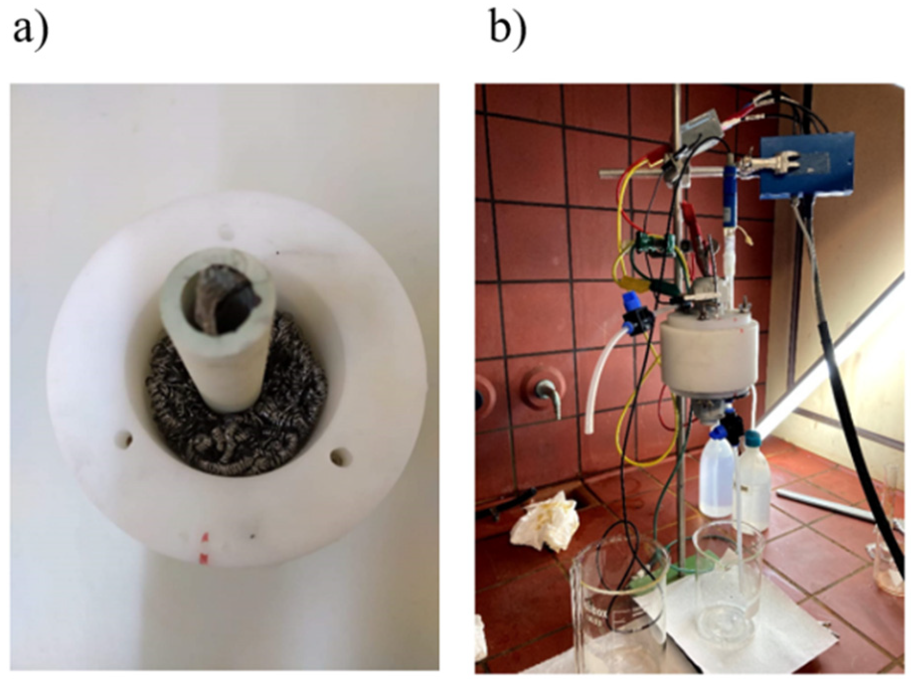
2.1. MFC Set up and Operation

A custom-made single-chamber MFC was constructed for this work, made of Ertalon® with an effective volume of 250 cm3 (Figure 1). As the anodic electrode, a commercially available stainless steel sponge (Nimax, Greece, item code 0857) was used, offering a high surface area for the development of the electrochemically active biofilm. The preparation of the cathode electrodes is presented separately. The MFC operated in batch mode and was acclimated with a synthetic glucose feed with anaerobic sludge inoculums (described in detail elsewhere [28,29]. The anaerobic sludge addition in the feed was carried out for the first three operation cycles; after that point, no more sludge was added in the feed. The anaerobic sludge was obtained from the Likovrisi (Athens, Greece) sewage treatment plant. The acclimation period of the MFC was completed once repeatable current output and COD removal were observed.
After the acclimation period of the MFC, the synthetic glucose feed was switched with the landfill leachate. To produce the leachate used as the MFC feedstock, the following process occurred. The liquid generated from a waste decomposition in a major Greek landfill unit in Athens, Greece was collected and treated with reverse osmosis (RO-CLR), resulting in a concentrated liquid residue. The characteristics of the liquid residue and the anaerobic sludge are presented in Table 1.

2.2. Cathodic Electrode Preparation

For the preparation of the ceramic cathodes, mullite tubes (Bonis S.A., Athens, Greece) (Figure 2a,b) with an outer diameter of 25 mm, a wall thickness of 2.5 mm and a length of 50 mm were used. Mullite tubes were used as the separators and as a structural support for the catalysts’ deposition. An acrylic-based binder (HSF54 paint, YSHIELD GmbH&Co. KG, Ruhstorf, Germany) and powdered activated carbon (Sigma-Aldrich, CAS 7440-44-0) were used as precursors for the production of the cathodic electrode catalyst. A stainless-steel grid was placed along the inner surface of the ceramic tube as the current collector before the application of the above techniques (Figure 2c).
To prepare the catalytic paste, 10 g of HSF54 and 5 g of Activated Carbon (AC) were mixed with 45 mL of a solvent consisting of 50% ethanol and 50% isopropanol. The same amounts were maintained across all the electrodes. The produced slurry was placed for 10 min in an EMMI 30 HC (EMMAG, Germany) sonication bath for homogenization. Sedimentation experiments were carried out in order to estimate the stability of the slurry. It was found that the slurry remained stable for at least 30 min, meaning that the subsequent procedures have to be carried out within this time frame. Afterwards, three different techniques were applied in order to produce ceramic-supported cathode electrodes. More specifically:
Wash-coat technique (WC): during this technique, the slurry was poured into the inner surface of the tube and left to dry physically (up to 24 h). Four repetitions at 2 min intervals were performed for the deposition of the slurry.
Brush-coat technique (BC): The slurry was brushed onto the inner surface of the tube with a paintbrush (size 4, Germany).
Sono-coat technique (SC): The slurry was poured up to the surface into the inner volume of the ceramic tube with a rubber cap at its bottom to prevent spilling (Figure 3a). A tip, producing ultrasound at the frequency of 20 kHz (Vibra cell 750, SONICS, USA), was placed 1 cm inside the tube. It was operated at 19% amplitude for 10 min (Figure 3b,c). After that time an ultrasound-assisted ceramic supported electrode was obtained, as depicted in Figure 3d.

2.3. Analytical Methods and Calculations

Chemical oxygen demand (COD), pH and conductivity characteristics of the leachate were measured prior and after each batch operation cycle for each produced cathode electrode. The measurements of COD were carried out according to standard methods [30]. The pH and the conductivity values were measured using a digital pH-meter (WinLab Data Line pH-meter, No: 210224Windaus Labortechnik, Germany) and a conductivity meter (CMD83, Radiometer Copenhagen, Analytical instruments Division, Hach, USA).
Electrochemical characterization of the whole cell with the three different cathode electrodes has been performed through a Potentiostat/Galvanostat (BIOLOGIC SP150, France) with a three-electrode setup, using a saturated Ag/AgCl reference electrode. Open-current voltage (OCV) was monitored, polarization curves from OCV to zero potential were obtained at a rate of 0.3 mV/s and electrochemical impedance spectroscopy (EIS) spectra were obtained from 200 kHz to 10 mHz with a sinusoidal amplitude of 10 mV. The power output of the cell was expressed in mW considering a leachate volume of 250 cm3. The mathematical model of the fitting analysis that was used was the same as reported in our previous references [31,32,33].

3. Results and Discussion

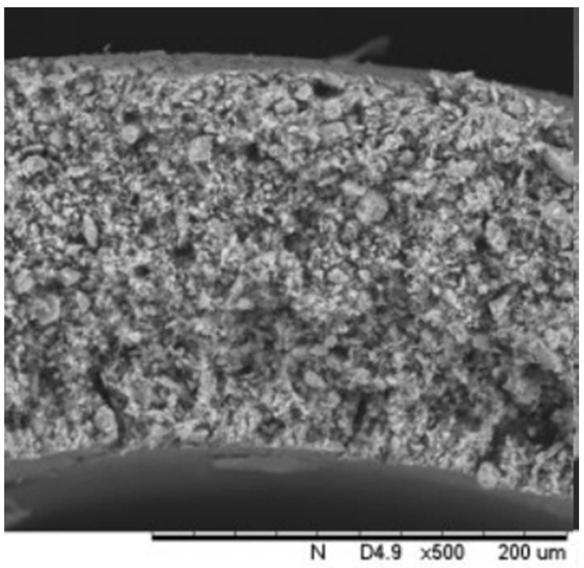
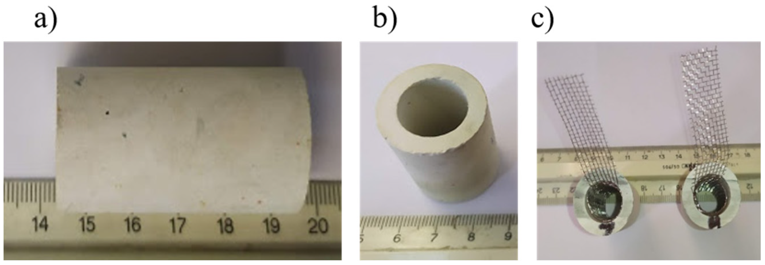
3.1. Characterization of Ceramic Supports (Mullite Tubes)

The SEM image (cross-section) of the mullite tube is depicted in Figure 4. The open porosity of the tubes was found to be at 20% according to the Archimedes method [34,35]. The tubes were washed and dried with deionized water prior to any use and then weighted in order to calculate the deposition mass of the catalyst (HSF54 + AC).

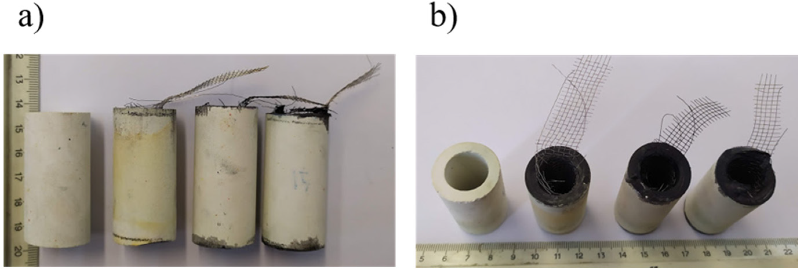
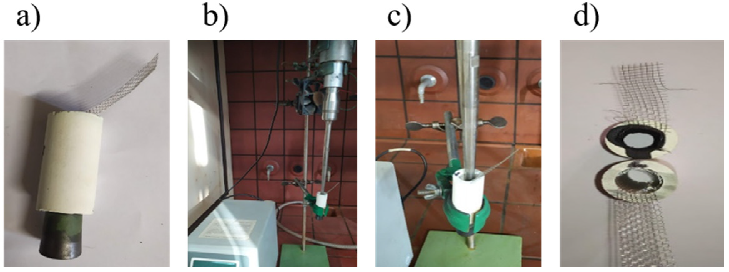
3.2. Ceramic-Supported Electrodes Production

All three preparation methods provided stable catalyst loadings (in the form of coatings) into the inner surface of the mullite tubes. The produced electrodes are depicted in Figure 5. In both pictures in Figure 5 the blank tube is shown at the left with the electrodes prepared with the three facile methods (WC, BC, SC) at the right side. The production of all coatings was uniform, and the physical properties of the produced electrodes are presented in Table 2. The values of Table 2 are the mean values of three samples.

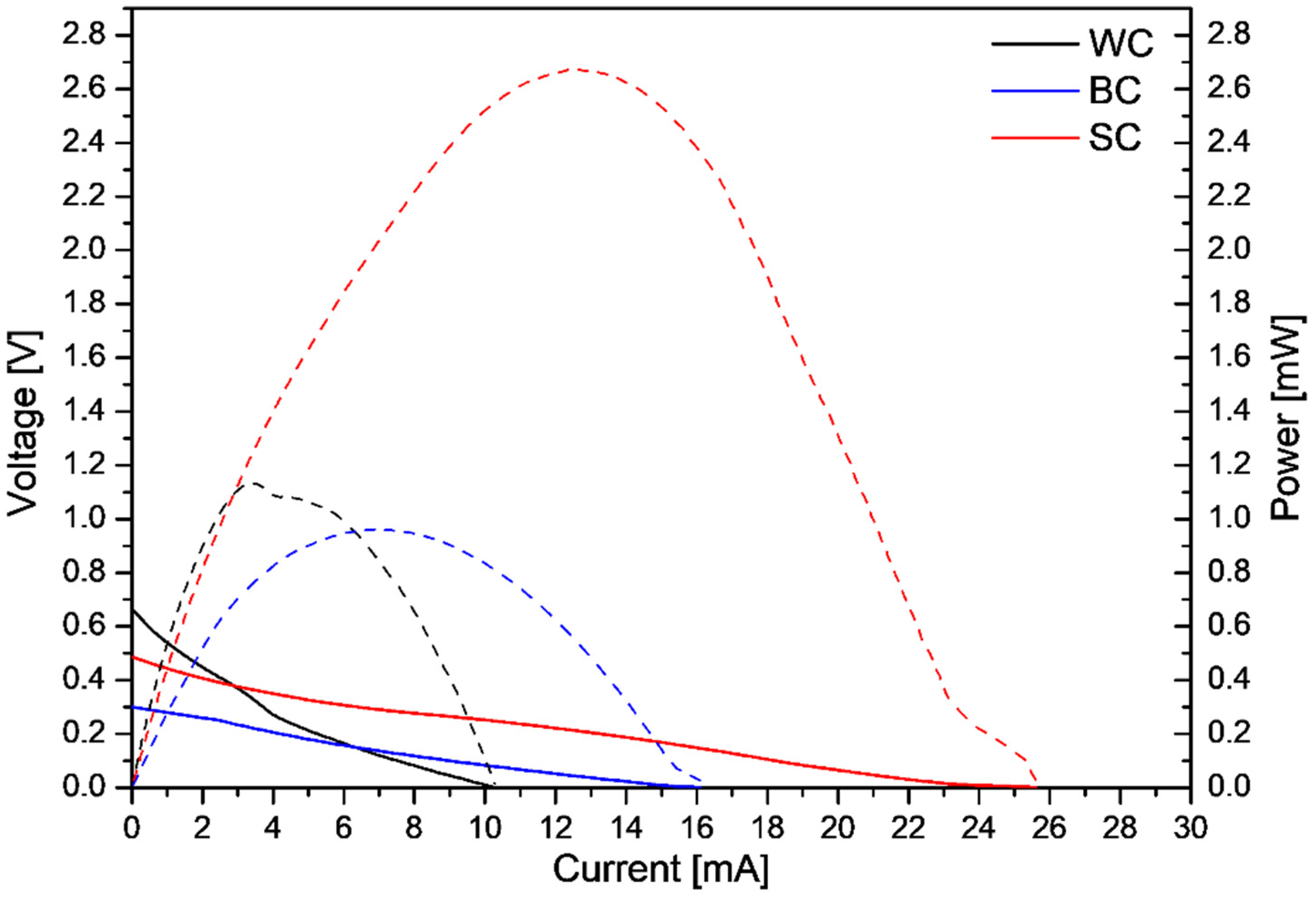
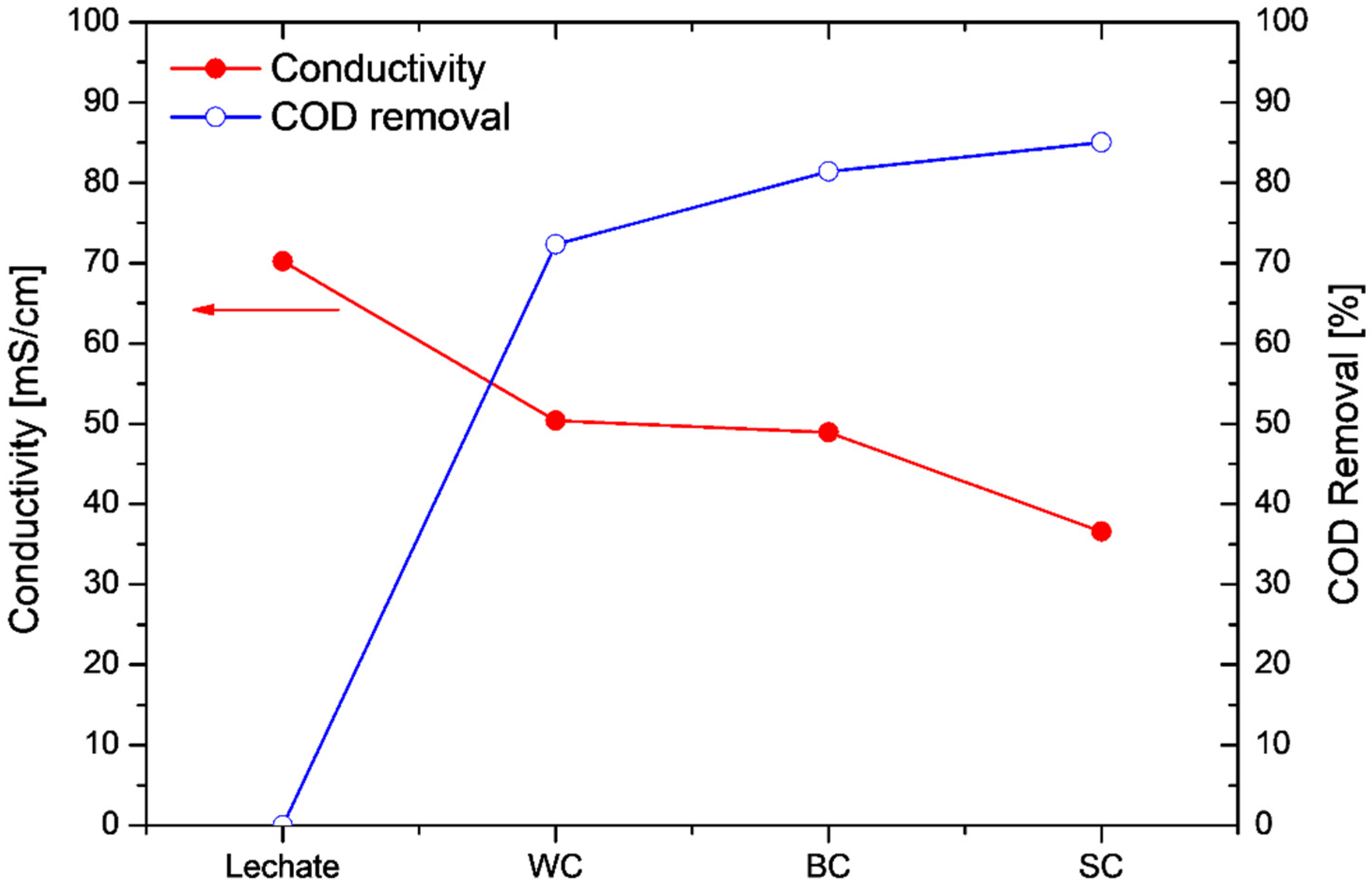
3.3. Batch Mode Operation Using Leachate as Substrate

The MFC operated in batch mode using the ceramic electrodes for the three different preparation techniques (WC, BC and SC). Polarization experiments determined the maximum power output values for the three different cases. Figure 6 presents the dependence of the MFC voltage, V, and the produced power, P, on the current passing through the MFC, when the MFC was set up with the different electrodes.
As can be seen from Figure 6, the maximum power output (2.67 mW) was obtained with the ceramic electrode produced with the SC technique. Additionally, the maximum power output for the MFC operation with the WC and BC electrodes was in the same range (WC: 1.12 and BC: 0.96 mW). Moreover, the slope of the V–I curves (Figure 6, continuous lines) indicated that ohmic losses dominated in the MFC, across the three electrode cases. Table 3 presents the open circuit values (OCV) and the maximum power output per catalysts mass and per volume of leachate, for the cycles’ operation with the different electrodes.
Figure 7 depicts the variations in the conductivity and the COD removal efficiency values at the end of each operation cycle in comparison with the initial values of the leachate: As can be seen from Figure 7, high COD removal efficiencies were achieved in all cases (COD removal > 70%), while the leachate conductivity decreased after its treatment. It is worth mentioning that the conductivity decreased by almost 50% when the wastewater was treated using the electrodes prepared with the SC technique. The conductivity decrease may be attributed to the decomposition of the substances present in the landfill leachate. The electrochemically active biofilm oxidizes the available substrate (leachate), decomposing the substances that contribute to the high conductivity, thus resulting in the decrease in the conductivity. A similar decrease in the anolyte’s conductivity has been observed elsewhere [36], although comparison between the two cases is difficult, due to the different acclimation, MFC set-up and feedstock conditions.

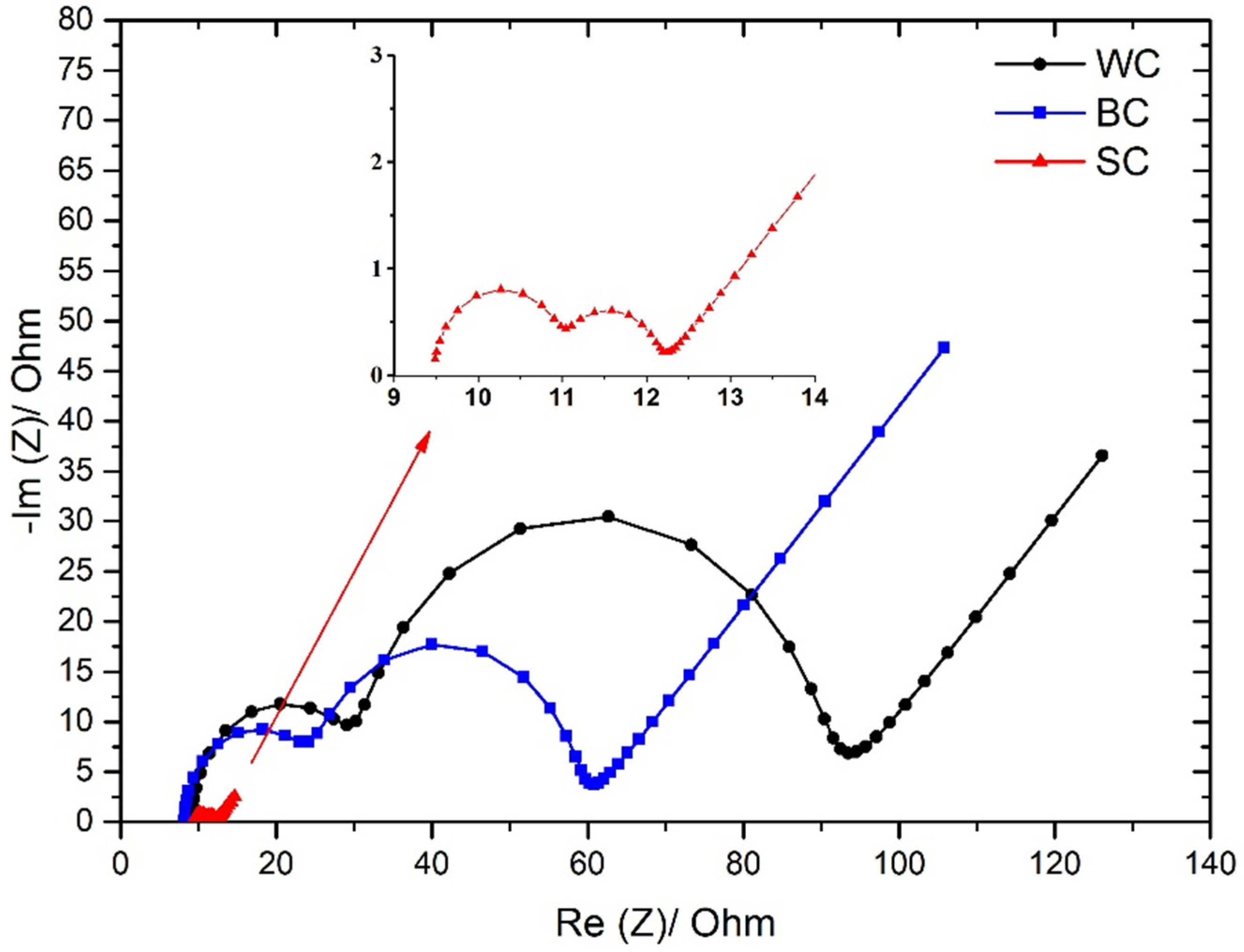
3.4. Electrochemical Impendance Spectroscopy Experiments (EIS)

In order to perform a detailed electrochemical characterization of the cell with the different electrodes, EIS experiments were carried out. From the electrochemical point of view, as reported elsewhere [37,38,39], the internal resistances of the cells with different electrodes can be calculated. In Figure 8, the Nyquist diagrams show significant information for the electrochemical processes that occur during the simultaneous wastewater treatment and electricity production.
All three setups depict two distinguished arcs followed by a Warburg element, as seen in other microbial fuel cells [40]. The fitted parameters are explained and reported in earlier publications, and the measurements here held through three electrode setups, as in most cases of fuel cells [32,33,41]. Table 4 presents the values of the solution resistance (Rs), the biofilm resistance (RBF), the charge transfer resistance (RCT), biofilm capacitance (CBF) and the charge transfer capacitance (CCT), which were calculated from the fitting model. Moreover, the internal resistance (Rin) of each case is presented.
As can be seen from Table 4, the Rin of SC electrodes is approximately 40% lower when compared with the Rin of the WC electrodes, and 28% lower from the Rin of the cell which operated with the BC electrodes. However, from the Nyquist diagrams, it is observed that this difference is attributed to the lower values of biofilm and charge resistances and capacitances of SC electrodes when compared with the respective values of WC and BC electrodes (Table 4). The solution resistance (RS~9.3 Ω) is practically the same for all three operation batch modes. This practically denotes that the nature of the electrolyte/leachate does not affect by any means the three setups. On the other hand, the values of RBF, RCT, CBF and the CCT, in the case of SC electrodes, are significantly lower when compared with the respective values of the BC and WC electrodes. This result indicates that the rate of the leachate oxidation is faster in the case of SC electrodes and also that a better biofilm has been developed in the case of SC electrodes [42,43]. On the contrary, no significant differences on the internal resistances are observed between WC and BC techniques. The above results are in accordance with the polarization experiments, which indicated that the maximum power output was produced with the SC electrodes where the maximum COD removal efficiency also occurred.

4. Conclusions

Three different preparation methods of producing tubular ceramic-supported electrodes capable of the oxygen reduction reaction (ORR) were evaluated under the view of maximizing the wastewater treatment and the power production of the MFC technology. High COD-removal efficiencies were achieved in wash-coat (WC), brush-coat (BC) and ultrasound-assisted (SC) deposition techniques, although the higher value was obtained using the electrodes produced from the SC technique (COD removal of 72%, 82% and 85% for the WC, BC and SC, respectively). Moreover, amongst WC, BC and SC deposition technique, the latter boosted the MFC performance in terms of the energy production (Pmax: 1.12 mW (WC), 0.96 mW (BC), 2.67 mW (SC). The electrochemical experiments verified that the operation of the cell with the ultrasound-assisted deposition technique operated with lower internal resistance (Rin 23.71 Ω) and specifically lower charge transfer and biofilm resistance when compared with the two other techniques (Rin: 39.6 Ω (WC), 32.91 Ω (BC)). These results indicated that the deposition technique of the cathodic catalyst has a major effect on the overall cell performance affecting not only the oxygen reduction reaction rate but also the biofilm development and the rate of the substrate oxidation. Further study is needed in order to determine the mechanisms that contribute to this performance boost when using the ultrasound-assisted deposition technique.

Author Contributions

Conceptualization, P.K.P. and A.T.; methodology, P.K.P., K.B., I.V. and A.T.; writing—original draft preparation, P.K.P.; writing—review and editing, A.T. and T.K.; supervision, P.K.P., C.A., V.N.S., A.T. and G.L.; resources, V.N.S., C.A. and G.L.; project administration, G.L. and A.T.; All authors have read and agreed to the published version of the manuscript.

Funding

This project has received funding from the Hellenic Foundation for Research and Innovation (HFRI) and the General Secretariat for Research and Technology (GSRT), under grant agreement No. 862.

Institutional Review Board Statement

Not applicable.

Informed Consent Statement

Not applicable.

Data Availability Statement

The datasets generated and analyzed during the current study are available from the corresponding author on reasonable request.

Acknowledgments

This project has received funding from the Hellenic Foundation for Research and Innovation (HFRI) and the General Secretariat for Research and Technology (GSRT) under grant agreement No. 862.

Conflicts of Interest

The authors declare no conflict of interest.

References

  1. Renou, S.; Givaudan, J.G.; Poulain, S.; Dirassouyan, F.; Moulin, P. Landfill leachate treatment: Review and opportunity. J. Hazard. Mater. 2008, 150, 468–493. [Google Scholar] [CrossRef] [PubMed]
  2. Tenodi, S.; Krčmar, D.; Agbaba, J.; Zrnić, K.; Radenović, M.; Ubavin, D.; Dalmacija, B. Assessment of the environmental impact of sanitary and unsanitary parts of a municipal solid waste landfill. J. Environ. Manag. 2020, 258, 110019. [Google Scholar] [CrossRef] [PubMed]
  3. Hasar, H.; Ipek, U.; Kinaci, C. Joint treatment of landfill leachate with municipal wastewater by submerged membrane bioreactor. Water Sci. Technol. 2009, 60, 3121–3127. [Google Scholar] [CrossRef] [PubMed]
  4. Roy, D.; Drogui, P.; Tyagi, R.D.; Landry, D.; Rahni, M. Mbr treatment of leachates originating from waste management facilities: A reference study of the design parameters for efficient treatment. J. Environ. Manag. 2020, 259, 110057. [Google Scholar] [CrossRef] [PubMed]
  5. Gkotsis, P.; Zouboulis, A.; Mitrakas, M. Using additives for fouling control in a lab-scale mbr; comparing the anti-fouling potential of coagulants, pac and bio-film carriers. Membranes 2020, 10, 42. [Google Scholar] [CrossRef] [PubMed] [Green Version]
  6. Hube, S.; Eskafi, M.; Hrafnkelsdóttir, K.F.; Bjarnadóttir, B.; Bjarnadóttir, M.Á.; Axelsdóttir, S.; Wu, B. Direct membrane filtration for wastewater treatment and resource recovery: A review. Sci. Total Environ. 2020, 710, 136375. [Google Scholar] [CrossRef]
  7. Chianese, A.; Ranauro, R.; Verdone, N. Treatment of landfill leachate by reverse osmosis. Water Res. 1999, 33, 647–652. [Google Scholar] [CrossRef]
  8. Ren, X.; Song, K.; Xiao, Y.; Zong, S.; Liu, D. Effective treatment of spacer tube reverse osmosis membrane concentrated leachate from an incineration power plant using coagulation coupled with electrochemical treatment processes. Chemosphere 2020, 244, 125479. [Google Scholar] [CrossRef]
  9. Santoro, C.; Flores-Cadengo, C.; Soavi, F.; Kodali, M.; Merino-Jimenez, I.; Gajda, I.; Greenman, J.; Ieropoulos, I.; Atanassov, P. Ceramic microbial fuel cells stack: Power generation in standard and supercapacitive mode. Sci. Rep. 2018, 8, 3281. [Google Scholar] [CrossRef] [Green Version]
  10. Tremouli, A.; Greenman, J.; Ieropoulos, I. Investigation of ceramic MFC stacks for urine energy extraction. Bioelectrochemistry 2018, 123, 19–25. [Google Scholar] [CrossRef]
  11. Li, W.W.; Sheng, G.P.; Liu, X.W.; Yu, H.Q. Recent advances in the separators for microbial fuel cells. Bioresour. Technol. 2011, 102, 244–252. [Google Scholar] [CrossRef] [PubMed]
  12. Zhang, P.; Yang, C.; Xu, Y.; Li, H.; Shi, W.; Xie, X.; Lu, M.; Huang, L.; Huang, W. Accelerating the startup of microbial fuel cells by facile microbial acclimation. Bioresour. Technol. Rep. 2019, 8, 100347. [Google Scholar] [CrossRef]
  13. Sakai, K.; Iwamura, S.; Sumida, R.; Ogino, I.; Mukai, S.R. Carbon paper with a high surface area prepared from carbon nanofibers obtained through the liquid pulse injection technique. ACS Omega 2018, 3, 691–697. [Google Scholar] [CrossRef]
  14. Li, S.; Cheng, C.; Thomas, A. Carbon-Based Microbial-Fuel-Cell Electrodes: From Conductive Supports to Active Catalysts. Adv. Mater. 2017, 29, 1–30. [Google Scholar] [CrossRef] [PubMed]
  15. Yaqoob, A.A.; Ibrahim, M.N.M.; Rafatullah, M.; Chua, Y.S.; Ahmad, A.; Umar, K. Recent advances in anodes for microbial fuel cells: An overview. Materials 2020, 13, 2078. [Google Scholar] [CrossRef] [PubMed]
  16. Tremouli, A.; Kamperidis, T.; Pandis, P.K.; Argirusis, C.; Lyberatos, G. Exploitation of Digestate from Thermophilic and Mesophilic Anaerobic Digesters Fed with Fermentable Food Waste Using the MFC Technology. Waste Biomass Valorization 2021, 12, 5361–5370. [Google Scholar] [CrossRef]
  17. Wang, P.; Lai, B.; Li, H.; Du, Z. Deposition of Fe on graphite felt by thermal decomposition of Fe(CO)5 for effective cathodic preparation of microbial fuel cells. Bioresour. Technol. 2013, 134, 30–35. [Google Scholar] [CrossRef]
  18. Guan, Y.F.; Zhang, F.; Huang, B.C.; Yu, H.Q. Enhancing electricity generation of microbial fuel cell for wastewater treatment using nitrogen-doped carbon dots-supported carbon paper anode. J. Clean. Prod. 2019, 229, 412–419. [Google Scholar] [CrossRef]
  19. Sayed, E.T.; Abdelkareem, M.A.; Alawadhi, H.; Elsaid, K.; Wilberforce, T.; Olabi, A.G. Graphitic carbon nitride/carbon brush composite as a novel anode for yeast-based microbial fuel cells. Energy 2021, 221, 119849. [Google Scholar] [CrossRef]
  20. Das, I.; Noori, M.T.; Bhowmick, G.D.; Ghangrekar, M.M. Application of low-cost transition metal based Co0.5Zn0.5Fe2O4 as oxygen reduction reaction catalyst for improving performance of microbial fuel cell. MRS Adv. 2018, 3, 3149–3154. [Google Scholar] [CrossRef]
  21. Rabaey, K.; Read, S.T.; Clauwaert, P.; Freguia, S.; Bond, P.L.; Blackall, L.L.; Keller, J. Cathodic oxygen reduction catalyzed by bacteria in microbial fuel cells. ISME J. 2008, 2, 519–527. [Google Scholar] [CrossRef] [PubMed]
  22. Daud, S.M.; Kim, B.H.; Ghasemi, M.; Daud, W.R.W. Separators used in microbial electrochemical technologies: Current status and future prospects. Bioresour. Technol. 2015, 195, 170–179. [Google Scholar] [CrossRef] [PubMed]
  23. Winfield, J.; Gajda, I.; Greenman, J.; Ieropoulos, I. A review into the use of ceramics in microbial fuel cells. Bioresour. Technol. 2016, 215, 296–303. [Google Scholar] [CrossRef] [PubMed] [Green Version]
  24. Jimenez, I.M.; Greenman, J.; Ieropoulos, I. Electricity and catholyte production from ceramic MFCs treating urine. Int. J. Hydrogen Energy 2017, 42, 1791–1799. [Google Scholar] [CrossRef] [PubMed] [Green Version]
  25. Chatterjee, P.; Ghangrekar, M.M. Preparation of a fouling-resistant sustainable cathode for a single-chambered microbial fuel cell. Water Sci. Technol. 2014, 69, 634–639. [Google Scholar] [CrossRef] [PubMed]
  26. Lv, K.; Zhang, H.; Chen, S. Nitrogen and phosphorus co-doped carbon modified activated carbon as an efficient oxygen reduction catalyst for microbial fuel cells. RSC Adv. 2018, 8, 848–855. [Google Scholar] [CrossRef] [Green Version]
  27. González, M.L.J.; Hernández Benítez, C.; Juarez, Z.A.; Zamudio Pérez, E.; Ramírez Coutiño, V.Á.; Robles, I.; Godínez, L.A.; Rodríguez-Valadez, F.J. Study of the effect of activated carbon cathode configuration on the performance of a membrane-less microbial fuel cell. Catalysts 2020, 10, 619. [Google Scholar] [CrossRef]
  28. Zhang, X.; Xia, X.; Ivanov, I.; Huang, X.; Logan, B.E. Enhanced activated carbon cathode performance for microbial fuel cell by blending carbon black. Environ. Sci. Technol. 2014, 48, 2075–2081. [Google Scholar] [CrossRef]
  29. Kamperidis, T.; Tremouli, A.; Pandis, P.K.; Lyberatos, G. In Condensate originating from household food waste as a substrate using microbial fuel cell technology. In Proceedings of the 17th International Conference on Environmental Science and Technology CEST2021, Athens, Greece, 1–4 September 2021. [Google Scholar]
  30. APHA/AWWA/WEF. Standard Methods for the Examination of Water and Wastewater; American Public Health Association: Washington, DC, USA, 2012. [Google Scholar] [CrossRef] [Green Version]
  31. Tremouli, A.; Karydogiannis, I.; Pandis, P.K.; Papadopoulou, K.; Argirusis, C.; Stathopoulos, V.N.; Lyberatos, G. Bioelectricity production from fermentable household waste extract using a single chamber microbial fuel cell. Energy Procedia 2019, 161, 2–9. [Google Scholar] [CrossRef]
  32. Tremouli, A.; Pandis, P.K.; Kamperidis, T.; Stathopoulos, V.N.; Argirusis, C.; Lyberatos, G. Performance assessment of a four-air cathode membraneless microbial fuel cell stack for wastewater treatment and energy extraction. E3S Web Conf. 2019, 116, 00093. [Google Scholar] [CrossRef]
  33. Tremouli, A.; Pandis, P.K.; Karydogiannis, I.; Stathopoulos, V.N.; Argirusis, C.; Lyberatos, G. Operation and electro(chemical) characterization of a microbial fuel cell stack fed with fermentable household waste extract. Glob. NEST J. 2019, 21, 253–257. [Google Scholar]
  34. Chalkia, V.; Pandis, P.; Stathopoulos, V. Shape forming of ceramic tubes for electrochemical reactors by gel-casting method. ECS Trans. 2015, 68, 2339–2348. [Google Scholar] [CrossRef]
  35. Pandis, P.; Kharlamova, T.; Sadykov, V.; Stathopoulos, V. Development of layered anode structures supported over apatite-type solid electrolytes. MATEC Web Conf. 2016, 41, 04001. [Google Scholar] [CrossRef] [Green Version]
  36. Kung, C.C.; Liu, C.C.; Sun, Y.; Yu, X. Innovative microbial fuel cell for energy harvesting. In Proceedings of the 2012 IEEE Energytech, Cleveland, OH, USA, 29–31 May 2012; pp. 1–4. [Google Scholar] [CrossRef]
  37. Hidalgo, D.; Sacco, A.; Hernandez, S.; Tommasi, T. Electrochemical and impedance characterization of microbial fuel cells based on 2d and 3d anodic electrodes working with seawater microorganisms under continuous operation. Bioresour. Technol. 2015, 195, 139–146. [Google Scholar] [CrossRef] [PubMed] [Green Version]
  38. Manohar, A.K.; Bretschger, O.; Nealson, K.H.; Mansfeld, F. The use of electrochemical impedance spectroscopy (eis) in the evaluation of the electrochemical properties of a microbial fuel cell. Bioelectrochemistry 2008, 72, 149–154. [Google Scholar] [CrossRef]
  39. Manohar, A.K.; Mansfeld, F. The internal resistance of a microbial fuel cell and its dependence on cell design and operating conditions. Electrochim. Acta 2009, 54, 1664–1670. [Google Scholar] [CrossRef]
  40. Lee, M.; Kondaveeti, S.; Jeon, T.; Kim, I.; Min, B. Influence of humidity on performance of single chamber air-cathode microbial fuel cells with different separators. Processes 2020, 8, 861. [Google Scholar] [CrossRef]
  41. Dominguez-Benetton, X.; Sevda, S.; Vanbroekhoven, K.; Pant, D. The accurate use of impedance analysis for the study of microbial electrochemical systems. Chem. Soc. Rev. 2012, 41, 7228–7246. [Google Scholar] [CrossRef]
  42. Martin, E.; Savadogo, O.; Guiot, S.R.; Tartakovsky, B. Electrochemical characterization of anodic biofilm development in a microbial fuel cell. J. Appl. Electrochem. 2013, 43, 533–540. [Google Scholar] [CrossRef]
  43. Ramasamy, R.P.; Sekar, N. Electrochemical impedance spectroscopy for microbial fuel cell characterization. J. Microb. Biochem. Technol. 2013, S6-004. [Google Scholar] [CrossRef] [Green Version]
Figure 1. (a) Single chamber MFC with stainless steel sponge as anode and mullite tube as cathode (b) MFC configuration for testing of constructed electrodes.
Applsci 12 02991 g001
Figure 2. (a) Horizontal image and (b) vertical image of mullite tubes prior to the electrode preparation, (c) mullite tubes internally coated with catalytic paste and stainless steel mesh.
Applsci 12 02991 g002
Figure 3. (a) Mullite tube with rubber cap, (b) and (c) setup of ultrasound-assisted deposition, (d) tube before and after ultrasound-assisted of HSF54 and AC deposition.
Applsci 12 02991 g003
Figure 4. Cross-section SEM image of mullite tube with open porosity.
Applsci 12 02991 g004
Figure 5. (a) Horizontal images and (b) vertical images of four mullite tubes with stainless steel mesh (left to right: blank, WC, BC, and SC).
Applsci 12 02991 g005
Figure 6. Polarization curves (V–I continuous lines) and power curves (P–I dashed lines) of the leachate-fed MFC for the three cathode electrode cases (WC Applsci 12 02991 i001, BC Applsci 12 02991 i002 and SC Applsci 12 02991 i003).
Applsci 12 02991 g006
Figure 7. Conductivity measurements (left) and COD removal values (right) for the leachate and the three leachate-fed MFC configurations with different cathode electrodes.
Applsci 12 02991 g007
Figure 8. Nyquist diagrams of leachate-fed MFC for three different cathode configurations (WC Applsci 12 02991 i001, BC Applsci 12 02991 i002 and SC Applsci 12 02991 i003).
Applsci 12 02991 g008
Table 1. Characteristics of processed leachate and anaerobic sludge used in the MFC.
SubstanceOrganic Load
(g COD/L)
pHConductivity
(mS/cm)
Leachate287.870
Anaerobic sludge227.35.2
Table 2. Physical properties of the three different produced cathode electrodes.
ElectrodeCoat Thickness
(mm)
Catalyst Mass
(g)
Conditions
WC1.51.54 wash coats
BC1.10.93 brush coats
SC0.80.710 min under ultrasound
Table 3. OCV and maximum power output values obtained from the leachate-fed MFC with the three different electrode cases examined.
ElectrodeOCV
(V)
Power Output
(mW)
Power Output
(mW·g−1)
Power Output
(mW·g−1·L−1)
WC0.661.121.56.00
BC0.310.960.93.84
SC0.482.670.710.68
Table 4. Fitting parameters from EIS measurements for the leachate-fed MFC with the three different electrode cases examined.
Fitted ParametersWCBCSC
RS (Ω)9.39.29.4
RBF (Ω)8.88.61.6
RCT (Ω)21.515.11.03
CBF (F)2.6 × 10−72.5 × 10−70.15 × 10⁻⁷
CCT (F)9.1 × 10−35.0 × 10−30.7 × 10⁻³
RINT (Ω) *39.632.9123.71
* calculated.
Publisher’s Note: MDPI stays neutral with regard to jurisdictional claims in published maps and institutional affiliations.

