Article

Geometric Design of a Face Gear Drive with Low Sliding Ratio

1
College of Mechanical and Electrical Engineering, Nanjing University of Aeronautics and Astronautics, Nanjing 210016, China
2
National Key Laboratory of Science and Technology on Helicopter Transmission, Nanjing University of Aeronautics and Astronautics, Nanjing 210016, China
*
Author to whom correspondence should be addressed.
Appl. Sci. 2022, 12(6), 2936; https://doi.org/10.3390/app12062936
Submission received: 20 February 2022 / Revised: 10 March 2022 / Accepted: 10 March 2022 / Published: 13 March 2022
(This article belongs to the Section Mechanical Engineering)

Abstract

:
A design method of low sliding ratio face gear drive is presented. The rack and gear meshing pair with a low sliding ratio is obtained by constructing the contact path. The face gear is then formed by this gear, and its tooth width characteristics are analyzed. Combined with the explicit solution of the meshing point of the tooth surface, a method to solve the sliding ratio of the proposed face gear pair is given, and the effects of relevant design parameters on the sliding ratio are analyzed. Moreover, the rationality of the tooth profile design is verified by 3D modeling and motion simulation. The proposed face gear pair has a lower sliding ratio, as well as larger tooth width, than those of traditional face gear drive (the pinion is involute spur gear) with the same basic parameters. The results of this study can provide points of reference for reducing friction and improving the mechanical efficiency of face gear drives.

1. Introduction

Face gear drive is a meshing transmission mechanism composed of cylindrical gear and bevel gear. Compared with the traditional spiral bevel gear transmission, it has the advantages of smaller volume, lighter weight, higher load-bearing capacity, better component force, which can meet the development requirements of future aviation equipment [1]. At present, the face gear drive has been successfully applied to the military [2,3] and civil industries [4], and the application scope and occasions will be broader. However, during the meshing process, there is relatively larger sliding friction between tooth surfaces, which will affect the operational life [5,6]. Therefore, it is necessary to develop a face gear drive with a low sliding ratio.
In view of the advantages of face gear transmission, many new face gear drives have been continuously reported. Litvin et al. [7] studied a design and analysis method for face gear drive with an involute helical involute pinion. Combining the characteristics of the worm drive, a larger gear ratio face gear drive was developed, which is composed of conical or cylindrical worms [8]. They also investigated a new geometry different from the existing one by application of asymmetric proles and double-crowned pinion of the drive [9]. This face gear drive can reduce the stresses and transmission errors. Zschippang et al. [10] presented a geometric design method for face gear with helix angle, shaft angle, and axle offset. Lin et al. [11,12] implemented the meshing theory of curve-face gear pair, which can achieve compound motion with much compact structure, better transmission efficiency, and load-bearing capacity than gear-linkage mechanism. For improving the performance and reducing the weight of noncircular gear transmission systems, Liu et al. [13] provided a novel spatial noncircular gear set comprising a cylinder gear and an eccentric face gear. Cui et al. [14] put forward a curved tooth surface gear, which has the characteristics of relatively simple technology, compact structure, low cost, high coincidence, stable transmission, and high load-bearing capacity than those of the general face gear drive. In addition, Tan [15] introduced a novel face gear drive with a conical involute pinion. Zhang and Wu [16] disclosed the tooth geometry of face gear drive with offset axes.
Thus far, the tooth profile design of the face gear drive with a low sliding ratio is rare, whereas the design of the cylindrical gear drive has been previously considered. Chang and Tsai [17] reported a parametric tooth profile of spur gear drive with a low sliding ratio. Kapelevich [18] advanced an asymmetric gear drive, which has a low sliding ratio. Xu et al. [19] improved the cycloid gear drive, and the sliding ratio is lower than that of involute gear. By controlling the relative curvature of the conjugate tooth profiles, Liu et al. [20] presented a design method for plane meshing tooth profiles, which can also be used as the design of gear drive with a low sliding ratio. Chen et al. [21] presented a pure rolling cylindrical helical gear drive with variable helix angles. Yeh et al. [22] implemented the deviation function (DF) method for the design of the conjugated tooth profiles, which can be used for designing the low sliding ratio gear drive. It is a more effective method to realize the design of a low-sliding plane meshing tooth profile by editing the meshing path, for example, the path combined with a straight line and a curve [23], and a specific arc path [24]. Additionally, Wang et al. [25,26] completed the design of the low sliding ratio tooth profile, which is based on the approximate range of the given sliding ratio.
As the sliding ratio is related to the operational life of the system, a low sliding ratio of the cylindrical gear drive has been developed. However, the sliding ratio has rarely been used as the design purpose to develop a novel face gear drive. In this paper, the sliding ratio is considered as the main design goal for the research of face gear drive. According to Buckingham [27], the face gear can be regarded as a rack with variable pressure angle and variable pitch, which is shown in Figure 1. The shaper of face gear is obtained from the rack, and a specific meshing path is given between the rack and the shaper to achieve the characteristics of a low sliding ratio. For this, the mathematical models of the face gear pair with a low sliding ratio are established. Then, the tooth width restriction conditions are studied, the effects of the given contact path function coefficients on the tooth width characteristics of the face gear are analyzed. The calculation methods of tooth surface meshing point and the sliding ratio are provided, and the effects of design parameters on the sliding ratio are studied. Finally, the rationality of the tooth profile design is verified by accurate modeling and motion simulation.

2. Mathematical Models of the Face Gear Pair with Low Sliding Ratio

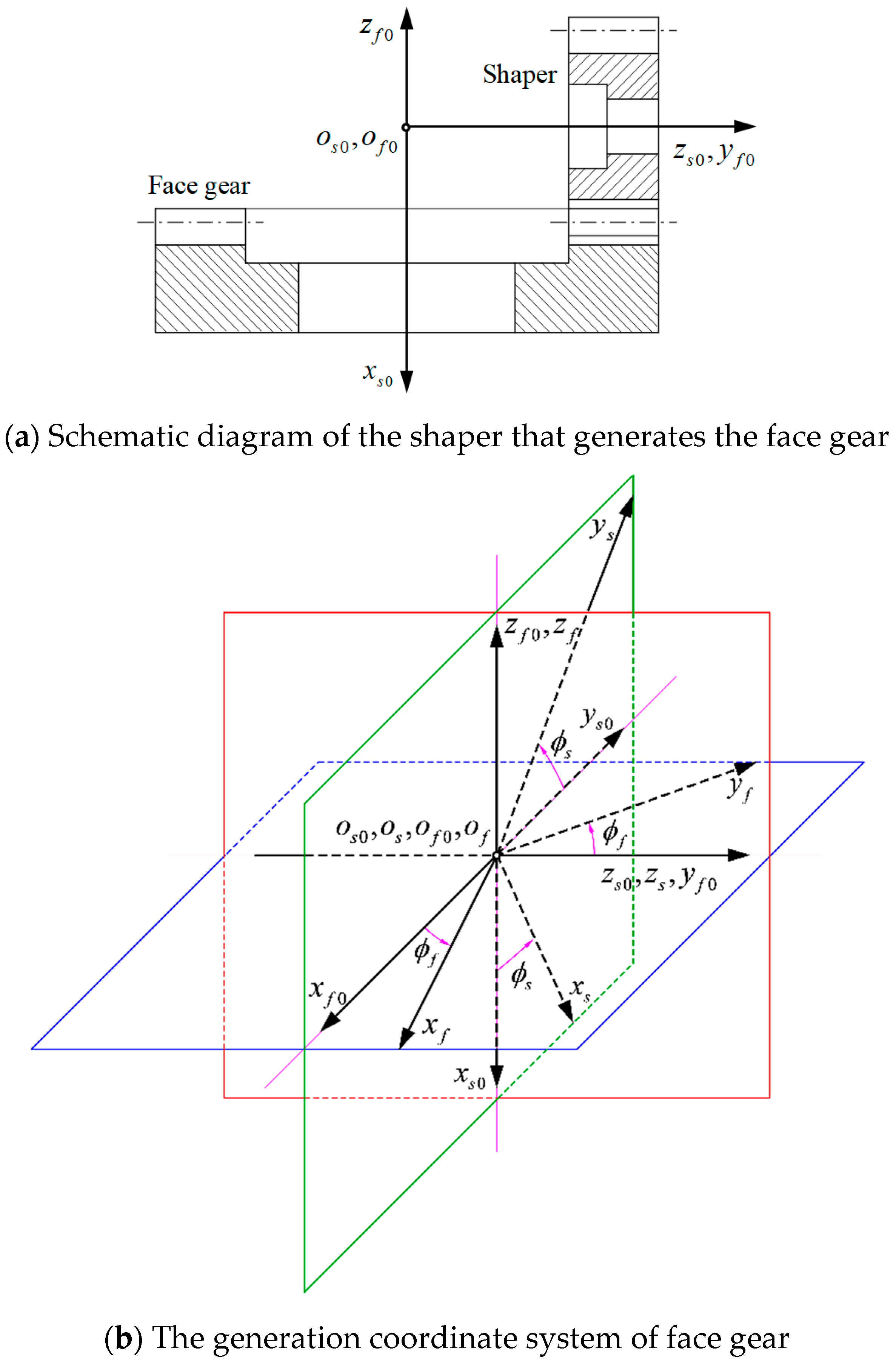
2.1. Construction of Shaper

According to the gear meshing theory, the shaper or pinion tooth surface can be achieved based on the meshing of the shaper and rack cutter. Additionally, the conjugate tooth profiles can be obtained from a given path of contact. Consequently, to obtain a low sliding ratio, the contact path Σ is represented by a given function, as illustrated in Figure 2. The coordinate systems S1(o1,x1,y1) and S2(o2,x2,y2) are rigidly attached to the shaper and rack cutter, respectively. S(o,x,y) is a fixed coordinate system whose origin o coincides with the pitch point P.
The equation of contact path Σ in S(o,x,y) can be defined as
y = f ( x )
It is assumed that the equation of rack profile Σr in S2(o2,x2,y2) is expressed as
Y = g ( X )
Based on the theory of gearing, the profile Σr can be defined as
{ X = ( y x ) d y + C Y = y
where C is an integration constant; let the initial meshing position of conjugated tooth profiles be at the pitch point P, then C = 0.
For this, Equation (3) can be further expressed as
{ X = ( y x d y d x ) d x Y = y
From Figure 2b, the kinematic relationship between gear and rack can be described: when the rack Σr translates leftwards to the position Ⅱ from the start position Ⅰ by the distance L, the shaper Σs rotates counterclockwise around the point o1 by the angle ϕ1 and meshes with Σr at the point B(x,y) of contact path Σ. Moreover, the point B corresponds to point B2(X,Y) of tooth profile Σr at the position Ⅰ. It is easy to know that BB2 = L = Xx, and ϕ1 can be expressed as
ϕ 1 = L r s = x + ( y x d y d x ) d x r s
where rs is the radius of the pitch circle of the shaper.
By coordinate transforming and integrating Equation (5), the coordinate of B can be derived in dashed coordinate system S1(o1,x1,y1) as
{ x 1 = x cos ϕ 1 + y sin ϕ 1 + r s sin ϕ 1 y 1 = x sin ϕ 1 + y cos ϕ 1 + r s cos ϕ 1
Thus, the work profiles of shaper can be presented as follows:
{ x 1 ( w ) = x cos ϕ 1 + ( y + r s ) sin ϕ 1 y 1 ( w ) = x sin ϕ 1 + ( y + r s ) cos ϕ 1 ϕ 1 = x + ( y x d y d x ) d x r s x [ x a , x b ]
where xa and xb are the addendum and dedendum parameters of the shaper, which can be solved by the following Equations (8) and (9), respectively.
x 1 2 + y 1 2 = ( r s + h a ) 2
a 1 x + a 2 x 3 = h f
where ha and hf are the addendum height and the dedendum height of shaper, respectively.
The fillet profiles of the gear can be obtained by the envelope movement of the generating rack’s tip. Therefore, the fillet profile of the shaper is expressed as
{ x 1 ( f ) = x cos ϕ 1 + ( r s h f ) sin ϕ 1 y 1 ( f ) = x sin ϕ 1 + ( r s h f ) cos ϕ 1 ϕ 1 = x + ( y x d y d x ) d x r s x [ 0 , x b ]
In order to obtain the rack and gear pair with a low sliding ratio, the relationship between the sliding ratio and meshing curve can be established from the solution method of sliding ratio.
δ 1 = v t ( 1 ) v t ( 2 ) v t ( 1 ) = 1 1 v t ( 1 ) v t ( 2 ) = 1 1 H + r s r s = H H + r s
δ 2 = v t ( 2 ) v t ( 1 ) v t ( 2 ) = 1 v t ( 1 ) v t ( 2 ) = 1 H + r s r s = H r s
where vt(1) and vt(2) are the tangential velocities of each tooth profile at the meshing point; H is the ordinate value of the intersection of the common tangent at the meshing point and the axis y.
From Equations (11) and (12), it can be seen that when the absolute values of H at the entry and exit points of engagement are as small as possible, the absolute value of the sliding ratio will also be as small as possible. Thus, the equation for the engagement path can be described by a cubic function as in Equation (13).
y = a 1 x + a 2 x 3 ,     ( a 1 < 0 ,   a 2 < 0 )
where the coefficients a1 and a2 should meet the following conditions: (1) the shaper tooth tip thickness should be greater than 0.3 times the modulus and (2) the contact ratio must be greater than 1.
To illustrate the low sliding ratio that can result from the provided meshing trajectory profile, a gear with module m = 4 mm, gear tooth number Ns = 32, coefficients a1 = −tan 20° and a2 = −0.001 is used as an example. The tooth profile and sliding ratio of the gear pair are shown in Figure 3.
It can be seen that the proposed rack-and-gear transmission has a lower sliding ratio, and the maximum sliding ratio is about 47% lower than that of the involute gear with the same basic parameters.

2.2. Construction of Face Gear Tooth Surface

The tooth surface of the face gear can be generated by the shaper. For this, first, four coordinate systems are set up, as depicted in Figure 4. Ss0(os0,xs0,ys0,zs0) and Sf0(of0,xf0,yf0,zf0) are fixed coordinate systems of shaper and face gear, respectively. Likewise, Ss(os,xs,ys,zs) and Sf(of,xf,yf,zf) are rigidly attached to the shaper and the face gear. Then, the origins of the four coordinate systems are at the same position, and the shaper and face gear perform rotation about the axis zs and zf, respectively.
The kinematic relationship between shaper and face gear can be described as follows: when the shaper rotates from coordinate system Ss0 to Ss by angle ϕs, the face gear rotates from Sf0 to Sf by angle ϕf. Then, the basic transformation matrixes between the coordinate systems are as follows:
M s 0 , s = ( cos ϕ s sin ϕ s 0 0 sin ϕ s cos ϕ s 0 0 0 0 1 0 0 0 0 1 )
M f 0 , s 0 = ( 0 1 0 0 0 0 1 0 1 0 0 0 0 0 0 1 )
M f , f 0 = ( cos ϕ f sin ϕ f 0 0 sin ϕ f cos ϕ f 0 0 0 0 1 0 0 0 0 1 )
M f , s = M f , f 0 M f 0 , s 0 M s 0 , s       = ( sin ϕ s cos ϕ f cos ϕ s cos ϕ f sin ϕ f 0 sin ϕ s sin ϕ f cos ϕ s sin ϕ f cos ϕ f 0 cos ϕ s sin ϕ s 0 0 0 0 0 1 )
where Ms0,s represents the transformation from coordinate system Ss to coordinate system Ss0; the others can then be compared.
In view of the production method, the two surfaces of the shaper are often set symmetrically with respect to the plane xsoszs. Then, the equation of shaper in Ss(os,xs,ys) is expressed as
r s ( x , h ) = ( x sin φ 0 + ( a 1 x + a 2 x 3 + r s ) cos φ 0 ± [ x cos φ 0 + ( a 1 x + a 2 x 3 + r s ) sin φ 0 ] h 1 )
where ‘±’ represents the left and the right side of the alveolar surface, respectively. φ0 is defined as
φ 0 = ( ( a 1 2 + 1 ) x + 4 3 a 1 a 2 x 3 + 3 5 a 2 2 x 5 ) r s + π 2 N s
According to the differential geometry theory, the unit normal vector ns of shaper tooth profile can be defined as
n s = r s x × r s h | r s x × r s h |
Then, the meshing equation between the shaper and the face gear is expressed as follows:
f ( x , h , ϕ s ) = n s v s ( s f ) = 0
where v(sf) is the relative velocity vector of the shaper and the face gear in Ss(os,xs,ys).
v s ( s f ) = v s ( s ) v s ( f )
where v(s) and v(f) are the velocity vector of the shaper and the face gear.
v s ( s ) = ω s × r s = ω s k s × r s
v s ( f ) = ω f × r s = ω f k f × r s
Considering the machining coordinate transforming relation, kf can be expressed at coordinate system Ss(os,xs,ys) as
k f = cos ϕ s i s + sin ϕ s j s
Thus, v(sf) is further expressed as
v s ( s f ) = ω s ( i f s z s sin ϕ s y s i f s z s cos ϕ s + x s i f s ( x s sin ϕ s + y s cos ϕ s ) )
where ifs is the gear ratio and satisfies the following equation:
i f s = ϕ f ϕ s = ω f ω s = N s N f
Through the coordinate transformation and meshing principle, the work surface equation the face gear coordinate system is defined as
r f ( w ) ( x , h , ϕ s , ϕ f ) = M f s ( ϕ s , ϕ f ) r s ( x , h ) = ( x s sin ϕ s cos ϕ f y s cos ϕ s cos ϕ f + z s sin ϕ f x s sin ϕ s sin ϕ f + y s cos ϕ s sin ϕ f + z s cos ϕ f x s cos ϕ s + y s sin ϕ s 1 )
The fillet surface of face gear can be formed by the edge of the addendum of shaper tooth profile. Therefore, the fillet surface equation is expressed as follows:
r f ( f ) ( x ( f ) , h , ϕ s , ϕ f ) = M f s ( ϕ s , ϕ f ) r s ( x ( f ) , h ) = ( x s sin ϕ s cos ϕ f y s cos ϕ s cos ϕ f + z s sin ϕ f x s sin ϕ s sin ϕ f + y s cos ϕ s sin ϕ f + z s cos ϕ f x s cos ϕ s + y s sin ϕ s 1 )
where x(f) is the parameter of the shaper addendum circle, which is solved by the following equation:
x s 2 + y s 2 = ( r s + h a ) 2

3. Tooth Width Characteristics
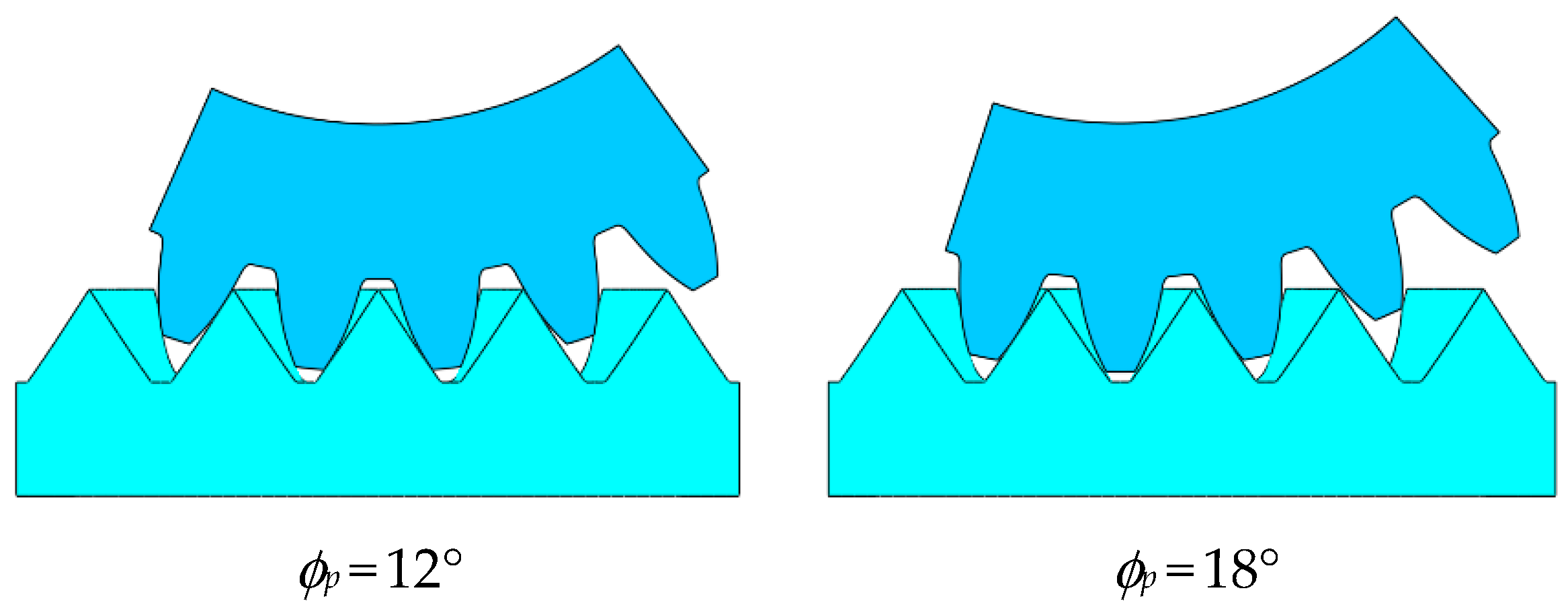
3.1. Undercutting

Undercutting is usually used as a criterion to restrict the face gear tooth inwards. The minimum inner radius can be determined by calculating the position of singular points on the generated face gear flank surfaces, which is no undercutting. According to a previous publication, the tooth surface will undercut, when the velocity of the two tooth surfaces meets the following relationship:
v s s + v s ( s f ) = v s f = 0
The differentiated equation of meshing is given by
f x x t + f h h t + f ϕ s d ϕ s d t = 0
Both Equations (31) and (32) yield a system of four linear equations of two unknowns (dx/dt, dh/dt), where df/dt is defined as chosen. This system of linear equations has a solution for the two unknowns if the following matrix K has the rank r = 2:
K = ( r s x r s h v s ( s f ) f x f h f ϕ s d ϕ s d t )
Δ 1 = ( x s x x s h v x s ( s f ) y s x y s h v y s ( s f ) f x f h f ϕ s d ϕ s d t ) = 0
Δ 2 = ( x s x x s h v x s ( s f ) z s x z s h v z s ( s f ) f x f h f ϕ s d ϕ s d t ) = 0
Δ 3 = ( y s x y s h v y s ( s f ) z s x z s h v z s ( s f ) f x f h f ϕ s d ϕ s d t ) = 0
Δ 4 = ( x s x x s h v x s ( s f ) y s x y s h v y s ( s f ) z s x z s h v z s ( s f ) ) = 0
The equality of the fourth sub-determinant Δ4 = 0 (based on the first three rows of matrix K) yields Equation (32) of meshing and is, therefore, not considered. Once Equation (38) is satisfied, undercutting will occur. If only one of the three Equations (34)–(37) is satisfied, singularities will appear.
g ( x , h , ϕ s ) = Δ 1 2 + Δ 2 2 + Δ 3 2 = 0
Both Equations (21) and (38) are used to solve the position of undercutting on the tooth surface. It should be mentioned that the search method is applied to solve the parameter x from the tip to the root of the shaper. The first value obtained is the tooth profile parameter of the minimum radius that does not undercut. Substitute the parameter x into the working tooth surface Equation (28) to obtain the position coordinates of the key points. The minimum inner radius RI to avoid undercutting can be obtained as
R I = x f 2 + y f 2

3.2. Pointing

Compared with cylindrical gears, the top width of face gears is not constant. In the enveloping process, the shaper tooth tip will cause the tooth surfaces on both sides of the tooth to intersect at a point, so the outer diameter tooth of the face gear is restricted. To accurately determine the position of the cusp, it is generally necessary to consider the equations of the tooth surfaces on both sides. However, due to the symmetrical distribution of the tooth surfaces on both sides, Equation (40) is adopted to analyze the tooth surface on one side.
{ x f ( x ( f ) , h , ϕ s ) = 0 z f ( x ( f ) , h , ϕ s ) = h a r s f ( x ( f ) , h , ϕ s ) = 0
After solving the cusp position parameters, they are substituted into the face gear working tooth surface equation to obtain the position coordinates of the cusp. The outer radius RO of the tip of the face gear can be expressed as
R O = x s sin ϕ s sin ϕ f + y s cos ϕ s sin ϕ f + z s cos ϕ f
Considering the undercutting and the pointing, the tooth width WT is defined as
W T = R O R I

3.3. Analysis of Tooth Width

The characteristics of the tooth width are widely concerned while designing the tooth profile of the face gear, which is related to the carrying capacity of the gear. The basic design parameters of the proposed face gear drive are listed in Table 1, and the coefficients of the contact path function as shown in Table 2.
From the above tables, the parameter groups D-1 to D-5 were used to analyze the effects of coefficient a1 on the tooth width. Similarly, through the parameter groups D-6 to D-9 and D-3, the effects of the coefficient a2 on these geometric features were studied, which are shown in Figure 5. It can be found that the inner radius and the outer radius increased, but the tooth width of the face gear decreased, as the coefficients a1 and a2 increased.
Moreover, from Figure 5b, it can be seen that the tooth width of the proposed gear drive D-3 is 8.2%, greater than that of the general gear drive D-6, due to the smaller inner radius of the proposed gear drive, as illustrated in Table 3.

4. Sliding Ratio Characteristics

4.1. Explicit Solution for Meshing Point

Generally, the face gear drive engages in the form of point contact, which can avoid eccentric load. In this paper, a pinion was chosen with 1–3 teeth less than the shaper as the driving wheel of the face gear pair, which is the same as that of the general face gear drive [28]. At present, the common idea for solving the contact points of the tooth surface is to establish the assembly relationship between the shaper, the pinion, and the face gear. The movement relationship between the pinion and the shaper is regarded as an imaginary internal meshing. Then, in the process of producing, the tooth surfaces of the shaper and face gear are in line contact at any time; the contact lines of shaper and face gear are denoted as LSF and LFS, as displayed in Figure 6. Similarly, the instantaneous contact lines for the meshing of the shaper and the pinion are denoted as LSP and LPS, respectively. Therefore, when the pinion meshes with the face gear, the contact that forms between the tooth surfaces is point contact. Additionally, the meshing points of face gear can be obtained by calculating the intersection point of the contact lines LSF and LSP, supplemented by coordinate transformation. This involves the solution of a system of equations, but the solution requires harsh initial values, which brings inconvenience to the solution [29]. Therefore, an explicit solution method is described below.
As for the above-mentioned meshing process, which is expressed in Equation (21), the parameter h can be obtained as follows:
h = C A sin ( φ 0 ± ϕ s ) + B cos ( φ 0 ± ϕ s )
with
A = 1 ( a 1 x + a 2 x 3 + r s ) ( a 1 2 + 1 + 4 a 1 a 3 x 2 + 3 a 3 2 x 4 ) / r s
B = ( a 1 + 3 a 2 x 2 ) ( a 1 2 x + x + 4 a 1 a 3 x 3 + 3 a 3 2 x 5 ) / r s
C = [ x ( a 1 x + a 2 x 3 + r s ) ( a 1 + 3 a 2 x 2 ) ] / i f s
φ 0 = ( ( a 1 2 + 1 ) x + 4 3 a 1 a 2 x 3 + 3 5 a 2 2 x 5 ) r s + π 2 N s
here, it contains two unknown quantities x and ϕs.
According to the meshing relationship between the shaper and the pinion, the relationship between the parameter x and rotation angle ϕs can be determined with Equation (47). Therefore, Equation (43) is further defined as Equation (48), and therefore, the rotation angle ϕs of the pinion can be expressed, which is the key point.
ϕ s = ( a 1 2 + 1 ) x + 4 3 a 1 a 3 x 3 + 3 5 a 3 2 x 5 r s N s 2 π = φ 0
h = x + ( a 1 x + a 2 x 3 + r s ) ( a 1 + 3 a 2 x 2 ) i f s [ ( a 1 + 3 a 2 x 2 ) + ( a 1 2 x + x + 4 a 1 a 2 x 3 + 3 a 2 2 x 5 ) / r s ]
Due to ϕs/ϕp = rp/rs, the rotation angle ϕp of pinion can be determined. Therefore, it is necessary to solve the value range of x. Combining Equations (7)–(9), it can be known that the parameters x of meshing point at the tooth tip (x = xc) and root (x = xd) of the pinion can be obtained as follows:
x 1 2 + y 1 2 = ( r p + h a ) 2
a 1 x + a 2 x 3 = h a
where x1 and y1 are defined by replacing rs with rp in Equation (7).
Consequently, according to x∈[xc, xd], the range of angle ϕp can be solved by Equation (47) and gear ratio, and h also can be obtained by Equation (48). On the other hand, based on the range of angle ϕp, for each given angle ϕp, the corresponding x can be solved by Equation (47) and gear ratio, and then h also can be obtained by Equation (48). Thus far, the explicit solution of the meshing points for the tooth surface is completed.
Using the calculation method of the tooth surface meshing point, the meshing points of the two face gears were carried out, as shown in Figure 7. Moreover, the effectiveness of the proposed method was verified by the intersection of the lines LSF and LSP (by coordinate transformation). The coordinate positions of the tooth surface meshing points of the proposed face gear were similar to those of the general face gear (the pinion was involute spur gear).

4.2. Solution of Sliding Ratio

The sliding ratio between the pinion Σp and face gear Σf can be interpreted, in a particularly short time, as the ratio of the relative arc length of the two surfaces sliding over the arc length of the tooth surface, as shown in Figure 8. At a certain instant, the two surfaces mesh at point M. After a short period of time, Σp and Σf move to Σp’ and Σf’, respectively. Moreover, the two surfaces mesh at point M’, and MM’ is the meshing track. The corresponding points of M’ on the Σp and Σf are Mp and Mf.
In a fixed coordinate system, v(p) and v(f) are the speeds of the two gears at the meshing point M. Similarly, vt(p) and vt(f) parameters represent the moving speed of point M along the meshing lines of MMp and MMf, which is also the velocity along the common tangent plane. vn(p) and vn(f) parameters represent the velocity along the common normal, both of which have the same mode length and direction. These vectors have the following relationship:
θ p = arccos v ( p ) n 0 | v ( p ) | | n 0 |
θ f = arccos v ( f ) n 0 | v ( f ) | | n 0 |
v t ( p ) = v ( p ) sin θ p
v t ( f ) = v ( f ) sin θ f
where n0 is the common normal vector at meshing point; θp (θf) is the angle between v(p) (v(f)) and n0.
Thus, combined with the definition of sliding ratio, the sliding ratios δp and δf of Σp and Σf are expressed as follows:
δ p = lim M M p 0 M M p M M f M M p = v t ( p ) v t ( f ) v t ( p ) = 1 v t ( f ) v t ( p )
δ f = lim M M f 0 M M f M M p M M f = v t ( f ) v t ( p ) v t ( f ) = 1 v t ( p ) v t ( f )
here, vt(p) and vt(f) need to be solved. The solution of them is described below.
As evident from Figure 4, in the fixed coordinate system Sf0(of0,xf0,yf0,zf0), the vector equation of the engagement point M is (x, 0.5 mNf, a1x + a2x3rp), and the angular velocity vectors of the pinion and face gears are (0, wp, 0) and (0, 0, wf).
v p = ω p × r M = ω p [ ( a 1 x + a 2 x 3 r p ) i x k ]
v f = ω f × r M = ω f [ r f i x j ]
The common normal vector n0 at that point is (x, 0, a1x + a2x3), and inserting n0, Equations (57) and (58) into Equations (51)–(54) yields
v t ( p ) = ω p [ x 2 + ( a 1 x + a 2 x 3 ) 2 ] [ ( a 1 x + a 2 x 3 r p ) 2 + x 2 ] r p 2 x 2 [ x 2 + ( a 1 x + a 2 x 3 ) 2 ]
v t ( f ) = ω f [ x 2 + ( a 1 x + a 2 x 3 ) 2 ] [ r f 2 + x 2 ] r f 2 x 2 [ x 2 + ( a 1 x + a 2 x 3 ) 2 ]
At this point, substituting vt(p) and vt(f) into Equations (55) and (56), the sliding ratios of pinion and face gear can be further expressed as
δ p = 1 r f ( x 2 + y 2 ) ( y 2 2 r p y + x 2 ) + r p 2 y 2 r p ( x 2 + y 2 ) x 2 + r f 2 y 2
δ f = 1 r p ( x 2 + y 2 ) x 2 + r f 2 y 2 r f ( x 2 + y 2 ) ( y 2 2 r p y + x 2 ) + r p 2 y 2

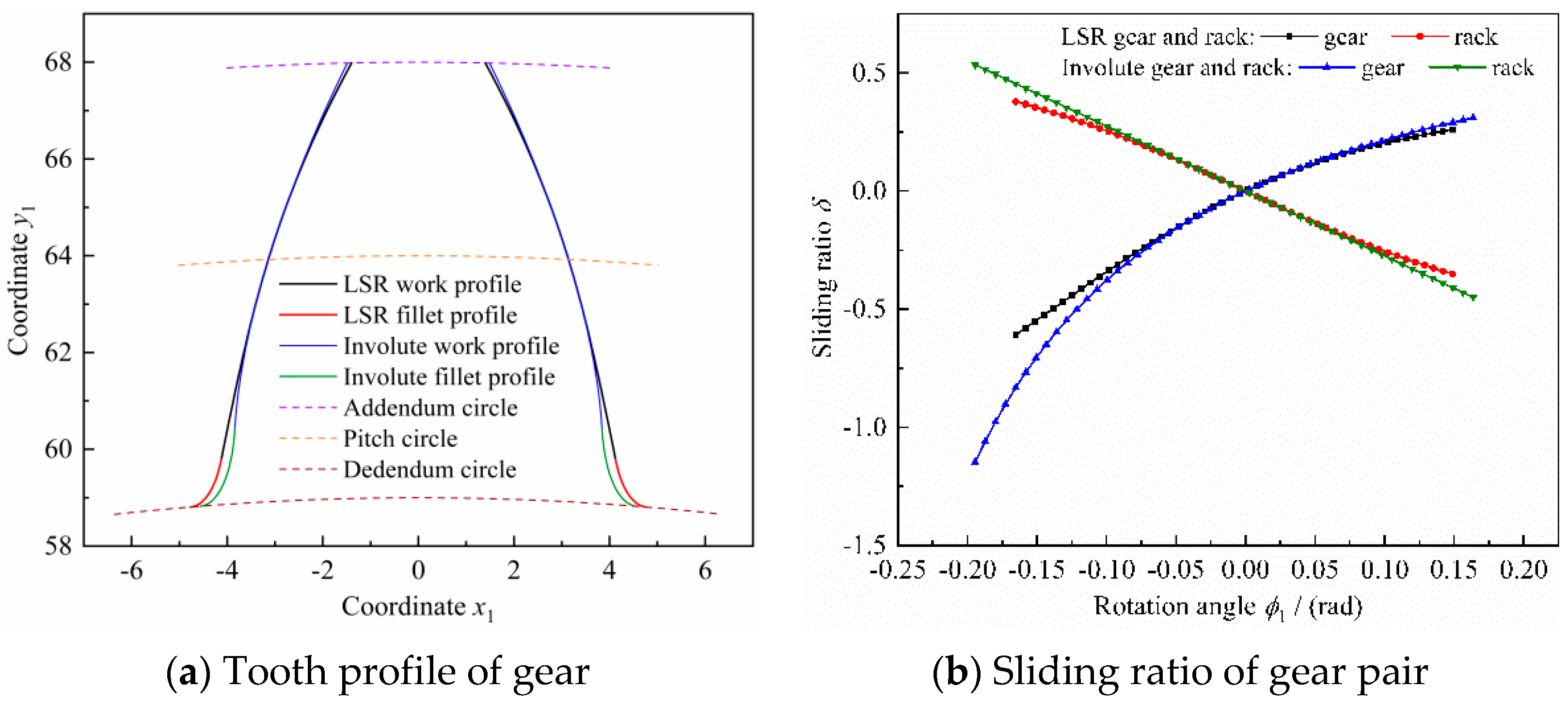
4.3. Analysis of Sliding Ratio

According to Table 1 and Table 2, the parameter groups D-1 to D-5 were used to analyze the effects of coefficient a1 on the sliding ratio. Similarly, the parameter groups D-6 to D-9 and D-3 were applied to study the effects of the coefficient a2 on the sliding ratio, the results of which are shown in Figure 9. It can be seen that, as the coefficient a1 or a2 decreased, the sliding ratio of face gear drive decreased.
Moreover, the maximum sliding ratios (absolute value) of this gear drive were lower than those of the general gear drive, as displayed in Table 4, through groups D-3 and D-6.
Given a face gear drive with a1 = −tan 20°, a2 = −0.001, m = [2, 2.5, 3, 3.5, 4] mm, and with other parameters being the same as Table 1, the sliding ratio of face gear pair were calculated, as shown in Figure 10. With the pinion parameters kept unchanged, and given the gear ratio as ipf = [2, 2.5, 3, 3.5, 4], the sliding ratio of the gear pair under different transmission ratio conditions are displayed in Figure 11. From Figure 10 and Figure 11, it can be deduced that, as the gear ratio or modulus increased, the sliding ratio of the proposed gear drive decreased.

5. Model Validation

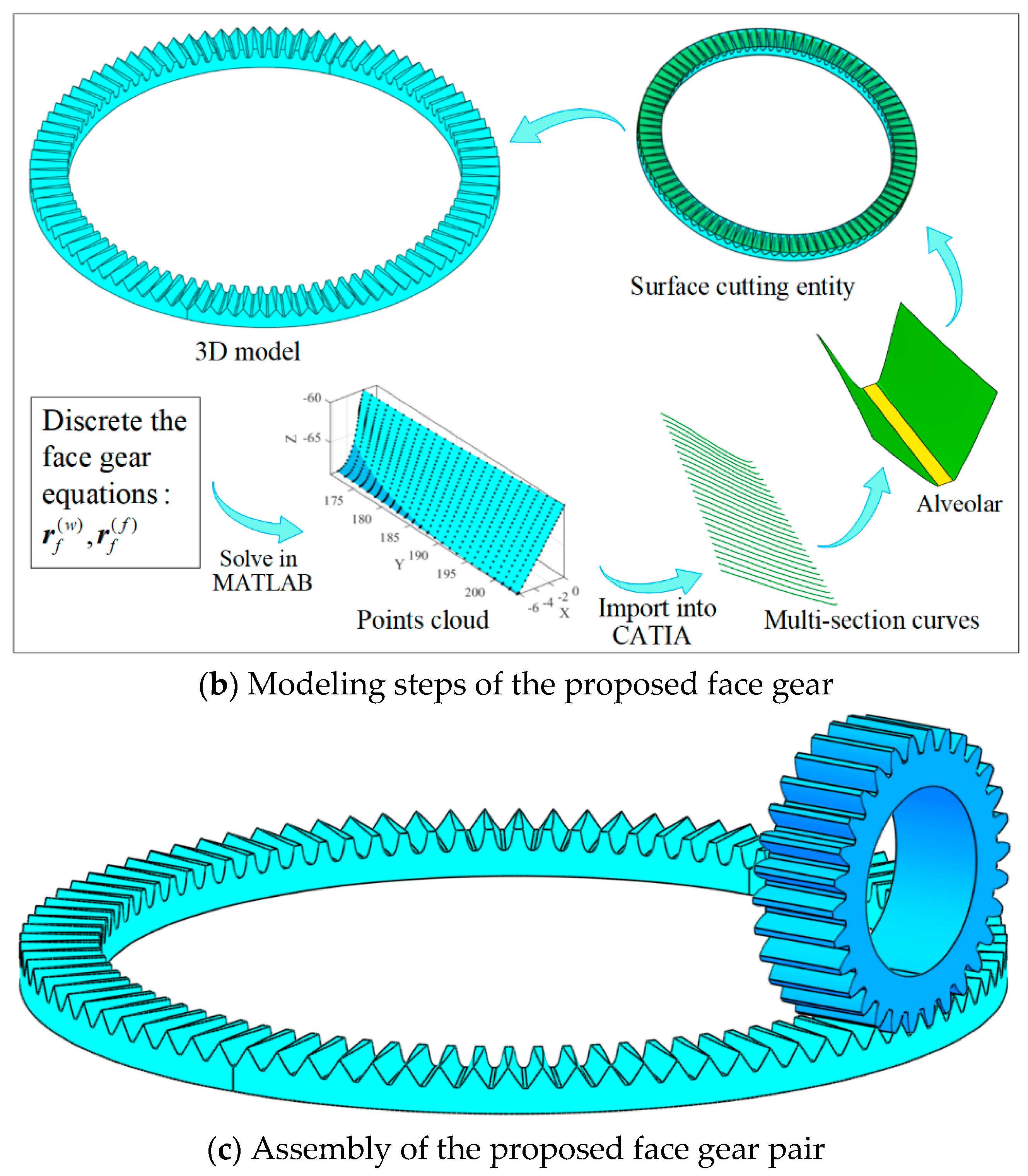
5.1. Modeling of Face Gear Pair

Generally, it is difficult to obtain the tooth surface model of a face gear pair directly from 3D software due to the complexity of the tooth surface. Commercial software CATIA V5 (produced by Dassault System) and MATLAB R2019a (produced by MathWorks) can be used for the parameterized modeling of complex surfaces, which mainly depends on the numerical calculation of MATLAB software and the accurate modeling of CATIA software for complex surfaces [30].
To realize the parametric modeling of the proposed pinion, the key steps are as follows:
(1) Parameter calculation: the ranges of parameters x corresponding to the working and the fillet tooth profile were calculated according to Equations (8) and (9);
(2) Solving tooth profile coordinates: the tooth surface coordinates xs, ys of the working tooth profile and the transition tooth profile were calculated according to Equations (7) and (10);
(3) Data output: the point data stored in the matrix were outputted to a specific Excel file. Then, they were imported into a 3D modeling software to continue the subsequent tooth surface modeling process. Additionally, the specific steps are shown in Figure 12a.
Similarly, the key steps for accurate modeling of face gear are as follows:
(1) Parameter calculation: the parameters corresponding to the minimum inner radius (to avoid undercutting) and the maximum outer radius (to avoid pointing) were calculated according to Equations (36) and (39), and then the range of zf was determined corresponding to the tooth height;
(2) Discrete tooth surface coordinates: coordinate yf was discretized along the tooth width direction to obtain a series of yfi; coordinate zf was discretized along the tooth height direction to obtain a series of zfj;
(3) Solving the tooth surface coordinate xf: According to yfi and zfj coordinates obtained by discretization, the surface equation was substituted to obtain the coordinate xfij;
(4) Data output: the point data stored in the matrix were cyclically outputted to a specific Excel file. Then, they were imported into a 3D modeling software to continue the subsequent tooth surface modeling process. Additionally, the specific steps are shown in Figure 12b.
Finally, the pinion and face gear models were used to build the gear pair assembly model, as shown in Figure 12c.

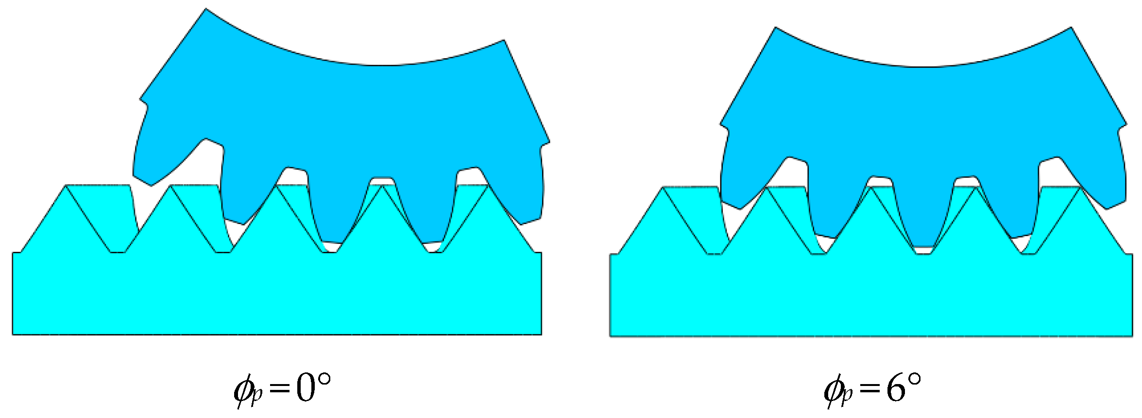
5.2. Motion Simulation

Motion simulation can be used to judge the rationality of the meshing pair movement, and also to determine whether there is interference between components [31]. In this study, based on the movement relationship between the two parts, motion simulation was carried out, as displayed in Figure 13. It can be observed that there was no interference between the two gears, as the rotation angle ϕp of the pinion changed. When a pair of gear teeth entered into meshing, the other pair of teeth had not yet exited meshing. Thus, the necessary continuity of action was ensured.

6. Conclusions

This paper presented a design method for face gear drive associated with a low sliding ratio. Based on the analysis and results, the conclusions are as follows:
(1) Based on the provided contact path function y = a1x + a2x3, general mathematical models of a pair of the conjugated spur gear and rack with low sliding ratio were given, including the working and the fillet profiles;
(2) Using the established spur gear as the shaper to envelope the face gear, the mathematical models of the working and the fillet surfaces of the face gear were obtained, and the tooth width restriction conditions were established, including the undercutting of the inner and the pointing of the outer. The results show that the tooth width of the proposed face gear was larger than that of general face gear, due to the smaller inner radius. Furthermore, as the coefficients a1 or a2 increased, the inner radius and the outer radius increased; conversely, the tooth width of the face gear increased.
(3) An explicit solution method for the contact point of the tooth surface of the face gear pair was provided, which is more convenient than the general solution method. Additionally, this method is also suitable for solving the meshing points of the general face gear drive, in which case, let a2 = 0;
(4) The calculation method of the sliding ratio of the spatial meshing of the face gear pair was studied, and the effects of design parameters on the sliding ratio were analyzed. The sliding ratio of the proposed face gear pair was lower than those of the general face gear pair. Moreover, as the coefficient a1 or a2 decreased, the sliding ratio of the face gear drive decreased.
(5) The rationality of the proposed face gear was demonstrated by accurate 3D modeling and motion simulation. However, to determine the optimum design and precision machining, further studies are needed.

Author Contributions

Conceptualization, W.S. and J.Z.; methodology, W.S.; software, J.Z.; validation, H.Z. and R.Z.; formal analysis, W.S. and J.Z.; investigation, R.Z.; resources, Z.L.; data curation, W.S.; writing—original draft preparation, W.S.; writing—review and editing, J.Z. and H.Z.; visualization, H.Z.; supervision, Z.L.; project administration, Z.L.; funding acquisition, Z.L. All authors have read and agreed to the published version of the manuscript.

Funding

This research was funded by National Key R&D Program of China, grant number 2019YFB2004700; National Natural Science Foundation of China, grant number 52175053; National Science and Technology Major Project, grant number 2019-VII-0017-0158.

Institutional Review Board Statement

Not applicable.

Informed Consent Statement

Not applicable.

Data Availability Statement

Not applicable.

Acknowledgments

This research was supported by National Key R&D Program of China (Grant No. 2019YFB2004700), National Natural Science Foundation of China (Grant No. 52175053), and National Science and Technology Major Project (Grant No. 2019-VII-0017-0158). The authors also sincerely appreciate the comments and suggestions for modifications made by the editors and anonymous referees.

Conflicts of Interest

The authors declare no conflict of interest.

References

  1. Litvin, F.L.; Fuentes, A. Gear Geometry and Applied Theory, 2nd ed.; Cambridge University Press: Cambridge, UK, 2004; ISBN 9780521815178. [Google Scholar]
  2. Litvin, F.L.; Wang, J.-C.; Bossler, R.B.; Chen, Y.-J.D.; Heath, G.F.; Lewicki, D.G. Application of face-gear drives in helicopter transmissions. J. Mech. Des. 1994, 116, 672–676. [Google Scholar] [CrossRef]
  3. Heath, G.; Slaughter, S.C.; Fisher, D.J.; Lewicki, D.G.; Fetty, J. Helical face gear development under the enhanced rotorcraft drive system program. In Proceedings of the 67th Annual Forum and Technology Display, Virginia Beach, VA, USA, 3–5 May 2011; Volume 3, pp. 2422–2433, NASA/TM-2011–217125. [Google Scholar]
  4. Benz, A. Cylkro® face gears: Dutch design and Swiss ingenuity cause transmission breakthrough. In Proceedings of the International Gear Conference 2014, Lyon, France, 26–28 August 2014; pp. 1184–1187. [Google Scholar]
  5. Choy, F.K.; Polyshchuk, V.; Zakrajsek, J.; Handschuh, R.F.; Townsend, D.P. Analysis of the effects of surface pitting and wear on the vibrations of a gear transmission system. Tribol. Int. 1994, 29, 77–83. [Google Scholar] [CrossRef]
  6. Morales-Espejel, G.E.; Rycerz, P.; Kadiric, A. Prediction of micropitting damage in gear teeth contacts considering the concurrent effects of surface fatigue and mild wear. Wear 2018, 398, 99–115. [Google Scholar] [CrossRef]
  7. Litvin, F.L.; Gonzalez-Perez, I.; Fuentes, A.; Vecchiato, D.; Hansen, B.D.; Binney, D. Design, generation and stress analysis of face-gear drive with helical pinion. Comput. Methods Appl. Mech. Eng. 2005, 194, 3870–3901. [Google Scholar] [CrossRef]
  8. Litvin, F.L.; Nava, A.; Fan, Q.; Fuentes, A. New geometry of face worm gear drives with conical and cylindrical worms: Generation, simulation of meshing, and stress analysis. Comput. Methods Appl. Mech. Eng. 2002, 191, 3035–3054. [Google Scholar] [CrossRef]
  9. Litvin, F.L.; Fuentes, A.; Howkins, M. Design, generation and TCA of new type of asymmetric face-gear drive with modified geometry. Comput. Methods Appl. Mech. Eng. 2001, 190, 5837–5865. [Google Scholar] [CrossRef]
  10. Zschippang, H.A.; Weikert, S.; Küük, K.A.; Wegener, K. Face-gear drive: Geometry generation and tooth contact analysis. Mech. Mach. Theory 2019, 142, 103576. [Google Scholar] [CrossRef]
  11. Lin, C.; He, C.; Hu, Y. Analysis on the kinematical characteristics of compound motion curve-face gear pair. Mech. Mach. Theory 2018, 128, 298–313. [Google Scholar] [CrossRef]
  12. Hu, Y.; Lin, C.; Li, S.; Yu, Y.; He, C.; Cai, Z. The Mathematical Model of Curve-Face Gear and Time-Varying Meshing Characteristics of Compound Transmission. Appl. Sci. 2021, 11, 8706. [Google Scholar] [CrossRef]
  13. Liu, D.; Wang, G.; Ren, T. Transmission principle and geometrical model of eccentric face gear. Mech. Mach. Theory 2017, 109, 51–64. [Google Scholar] [CrossRef]
  14. Cui, Y.; Fang, Z.; Su, J.; Feng, X. Precise modeling of arc tooth face-gear with transition curve. Chin. J. Aeronaut. 2013, 26, 1346–1351. [Google Scholar]
  15. Tan, J. Face gearing with a conical involute pinion: Part 2—The face gear: Meshing with the pinion, tooth geometry and generation. In Proceedings of the ASME 2003 International Design Engineering Technical Conferences and Computers and Information in Engineering Conference, Chicago, IL, USA, 2–6 September 2003; pp. 297–306. [Google Scholar]
  16. Zhang, Y.; Wu, Z. Offset Face Gear Drives: Tooth geometry and contact analysis. J. Mech. Des. 1997, 119, 114–119. [Google Scholar] [CrossRef]
  17. Chang, H.L.; Tsai, Y.C. A mathematical model of parametric tooth profiles for spur gears. J. Mech. Des. 1992, 114, 8–16. [Google Scholar] [CrossRef]
  18. Kapelevich, A. Geometry and design of involute spur gears with asymmetric teeth. Mech. Mach. Theory 2000, 35, 117–130. [Google Scholar] [CrossRef]
  19. Xu, L.; Li, S.; Wang, W. Sliding ratio for novel cycloidal gear drive. Proc. Inst. Mech. Eng. Part C J. Mech. Eng. Sci. 2017, 232, 3954–3963. [Google Scholar] [CrossRef]
  20. Liu, L.; Meng, F.; Ni, J. A novel non-involute gear designed based on control of relative curvature. Mech. Mach. Theory 2019, 140, 144–158. [Google Scholar] [CrossRef]
  21. Chen, Z.; Zeng, M.; Fuentes, A. Computerized design, simulation of meshing and stress analysis of pure rolling cylindrical helical gear drives with variable helix angle. Mech. Mach. Theory 2020, 153, 103962. [Google Scholar] [CrossRef]
  22. Yeh, T.; Yang, D.C.H.; Tong, S.-H. Design of new tooth profiles for high-load capacity gears. Mech. Mach. Theory 2001, 36, 1105–1120. [Google Scholar] [CrossRef]
  23. Fong, Z.-H.; Chiang, T.-W.; Tsay, C.-W. Mathematical model for parametric tooth profile of spur gear using line of action. Math. Comput. Model. 2002, 36, 603–614. [Google Scholar]
  24. Wang, Y.; Ren, S.; Li, Y. Design and manufacturing of a novel high contact ratio internal gear with a circular arc contact path. Int. J. Mech. Sci. 2019, 153, 143–153. [Google Scholar] [CrossRef]
  25. Wang, J.; Luo, S.; Wu, R. A method for the preliminary geometric design of gear tooth profiles with small sliding coefficients. J. Mech. Des. 2010, 132, 054501. [Google Scholar] [CrossRef]
  26. Wang, J.; Liang, H.; Luo, S.; Wu, R. Active design of tooth profiles using parabolic curve as the line of action. Mech. Mach. Theory 2013, 67, 47–63. [Google Scholar] [CrossRef]
  27. Buckingham, E. Analytical Mechanics of Gears; McGraw-Hill: New York, NY, USA, 1949. [Google Scholar]
  28. Litvin, F.L.; Zhang, Y.; Wang, J.-C.; Bossler, R.B.; Chen, Y.-J.D. design and geometry of face-gear drives. J. Mech. Des. 1992, 114, 642–647. [Google Scholar] [CrossRef]
  29. Chang, S.-H.; Chung, T.-D.; Lu, S.-S. Tooth contact analysis of face-gear drives. Int. J. Mech. Sci. 2000, 42, 487–502. [Google Scholar] [CrossRef]
  30. Wu, Y.; Zhou, Y.; Zhou, Z.; Tang, J.; Ouyang, H. An advanced CAD/CAE integration method for the generative design of face gears. Adv. Eng. Softw. 2018, 126, 90–99. [Google Scholar] [CrossRef]
  31. Sheng, W.; Li, Z.; Zhang, H.; Zhu, R. Geometry and design of spur gear drive associated with low sliding ratio. Adv. Mech. Eng. 2021, 13, 16878140211012547. [Google Scholar] [CrossRef]
Figure 1. Approximate tooth profile of face gear.
Applsci 12 02936 g001
Figure 2. Generation of the shaper.
Applsci 12 02936 g002
Figure 3. Tooth profile and sliding ratio of gear pair.
Applsci 12 02936 g003
Figure 4. Generation of the face gear.
Applsci 12 02936 g004
Figure 5. Effects of a1 and a2 on tooth width characteristics.
Applsci 12 02936 g005
Figure 6. Instantaneous meshing lines on the shaper.
Applsci 12 02936 g006
Figure 7. Meshing points of two face gears.
Applsci 12 02936 g007
Figure 8. Relative sliding of tooth surfaces.
Applsci 12 02936 g008
Figure 9. Effect of a1 and a2 on sliding ratio.
Applsci 12 02936 g009
Figure 10. Effect of module m on sliding ratio.
Applsci 12 02936 g010
Figure 11. Effect of gear ratio ipf on sliding ratio.
Applsci 12 02936 g011
Figure 12. Modeling of the proposed face gear pair.
Applsci 12 02936 g012aApplsci 12 02936 g012b
Figure 13. Motion simulation of the proposed face gear pair.
Applsci 12 02936 g013aApplsci 12 02936 g013b
Table 1. The basic design parameters of the face gear drive.
Design ParametersValue
Module m (mm)4
Tooth number of pinion Np30
Tooth number of shaper Ns32
Tooth number of face gear Nf90
Addendum coefficient ha*1.0
Head clearance coefficient c*0.25
Table 2. Coefficients of the contact path function.
Design ParametersCoefficient a1Coefficient a2
D-1−tan 18°−0.001
D-2−tan 19°−0.001
D-3−tan 20°−0.001
D-4−tan 21°−0.001
D-5−tan 22°−0.001
D-6−tan 20°0
D-7−tan 20°−0.0005
D-8−tan 20°−0.0015
D-9−tan 20°−0.002
Table 3. Comparison of two face gears tooth width.
Tooth Width ParametersThe Proposed Face Gear (D-3)The General face Gear (D-6)
Inner radius (mm)170.490173.059
Outer radius (mm)203.135203.231
Tooth width (mm)32.64530.172
Table 4. Comparison of sliding ratio for the two gear drives.
Sliding
Ratio
The Proposed Face Gear Drive (D-3)The General Face Gear Drive (D-6)
PinionFace GearPinionFace Gear
Root of tooth−0.6041−0.3931−0.9285−0.5455
Top of tooth0.28220.37660.35300.4815
Publisher’s Note: MDPI stays neutral with regard to jurisdictional claims in published maps and institutional affiliations.

