1. Introduction
Noncircular gear is a mechanism that can realize the non-uniform speed ratio transmission between the driving gear and driven gear [
1]. It is widely used in agriculture, textile, instruments, and other fields because of its advantages of low economic cost, compact structure, accurate transmission ratio, high efficiency, strong bearing capacity, and high precision. In the 14th century, high precision noncircular gear mechanism began to be used in astronomical clocks [
2]. After the 20th century, many scholars have carried out the research on noncircular gear and made great progress in related design theory and engineering application.
Litvin et al. [
1] carried out systematic research on the design and manufacture of noncircular gear. Liu et al. [
3] studied the application of a noncircular gear train in the generation of specific trajectory curve. Mundo et al. [
4,
5] studied the tooth surface design method, motion characteristics, and application occasions of noncircular gear planetary transmission, as well as the noncircular gear five-link mechanism, and optimized the connecting rod curve of the traditional five-link mechanism based on the noncircular gear. Ottaviano et al. [
6] studied the kinematic characteristics of noncircular gear and cam function generator through numerical calculation and experimental analysis. Modler et al. [
7] made a comprehensive analysis on the mechanism of noncircular gear linkage, including the types and mechanical characteristics of noncircular gear linkage, which laid a theoretical foundation for its application. Alexandru et al. [
8] deeply studied the characteristics and geometric design method of variable transmission ratio steering gear. Zheng et al. [
9] combined the principle of noncircular gear differential gear train and the motion requirements of indexing device and proposed a new noncircular gear indexing device. This device has the characteristics of large indexing of a planetary indexing cam mechanism, more compact structure, and fewer parts. Yu et al. [
10] carried out simulation and experimental research on the surface topography and machining surface quality of noncircular gear in ball end milling. Based on the research of plane noncircular gear, Lin and Gong et al. [
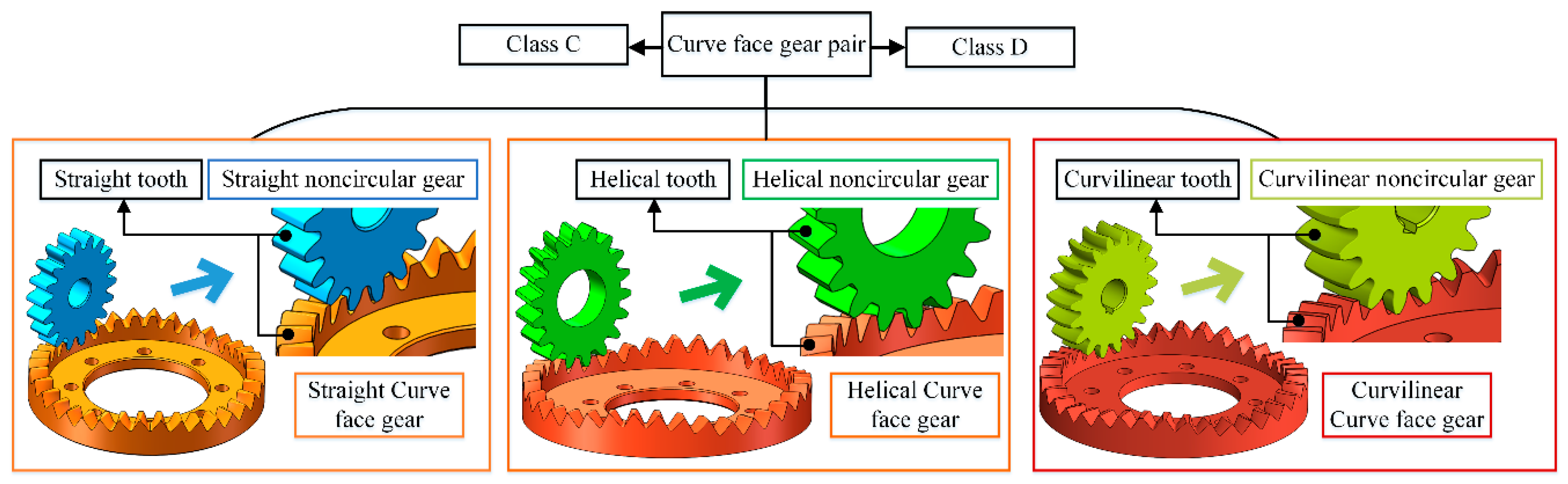
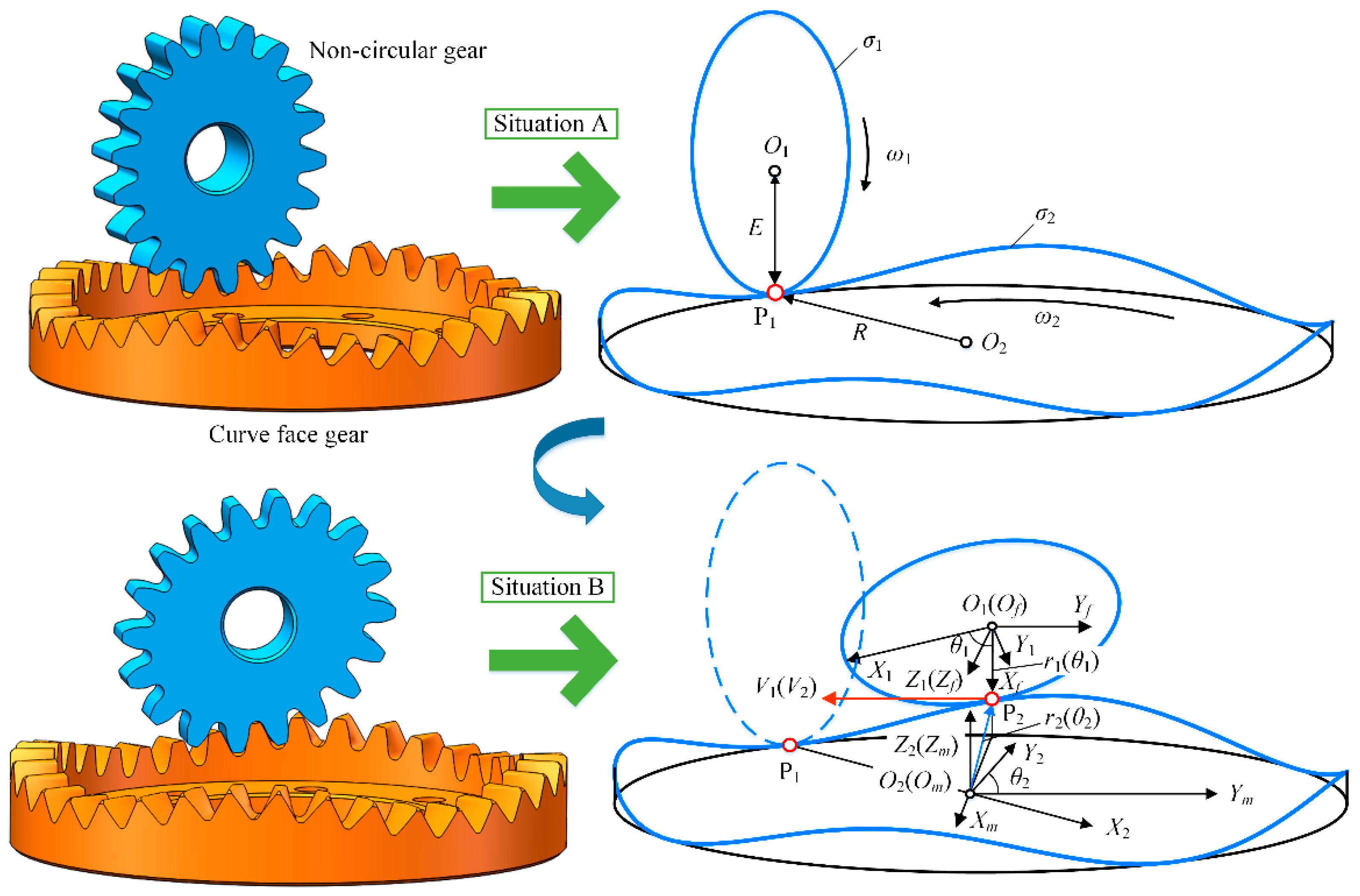
11] creatively proposed a new type of curve face gear pair, which can realize the variable transmission ratio transmission between intersecting shafts, and analyzed its principle and motion characteristics. Lin and Zeng et al. [
12] analyzed the design and tooth width characteristics of helical curve face gear pair. Lin and Yu et al. [
13,
14] studied the composite motion characteristics and bending stress of high-speed curve face gear pair. Hu et al. [
15] studied the mathematical model of curve face gear and time-varying meshing characteristics of compound transmission, and found that this gear pair can be used for the focusing mechanism.
In the field of gear CVT, there have been a few studies. Dooner et al. [
16] proposed a noncircular gear CVT device based on the summation differential principle, and dealt with its kinematic characteristics and circulating power. Sun et al. [
17] proposed a heart-shaped gear CVT device based on the principle of noncircular gear variable transmission ratio, and introduced its mathematic model and kinematic characteristics. According to the crank slider principle and eccentric cam principle, Zhu and Wang proposed a gear infinitely variable transmission with control function [
18,
19] and a novel gear infinitely variable transmission based on the scotch yoke systems [
20]. They can be applied to vehicle and wind turbine, and the simulation and experimental analysis were carried out. Chen et al. [
21] proposed a new rod gear pulse CVT and analyzed its transmission characteristics and phase number optimization. Compared with the other traditional CVT, it has a wider variable range of transmission ratio and smaller pulsation rate while reducing volume.
The above mechanisms can realize CVT in a certain sense, but there is still some room for improvement in the overall transmission characteristics and meshing performance, like transmission type, mechanism volume, design difficulty, kinematic characteristics, transmission efficiency and bearing capacity. In order to improve the above performance, according to the transmission ratio integration method consisting of addition method and multiplication method, the spatial noncircular gear CVT was proposed. Here, noncircular gear pair and curve face gear pair are collectively referred to as spatial noncircular gear pair. Firstly, in terms of transmission type and mechanism volume, the spatial noncircular gear CVT contains multiple transmission patterns. According to the requirements of different working conditions, different spatial noncircular gear CVT pattern can be selected. In addition, for design difficulty and mechanism kinematic characteristics, the spatial noncircular gear CVT mechanism combined the characteristics of a spatial noncircular gear pair, a transmission ratio changing mechanism, a transmission selection mechanism, and multiple branches. It can dynamically adjust the design parameters according to the actual transmission ratio requirements to realize the CVT with the input rotation angle in the whole range. Based on the tooth profile classification design method, the spatial noncircular gear with different tooth profiles can be obtained. Finally, compared with other transmission forms, spatial noncircular gear transmission, as a meshing transmission form, has high bearing capacity and transmission efficiency. In summary, this study can provide a new idea for vehicles and special vehicles with special transmission needs to realize CVT.
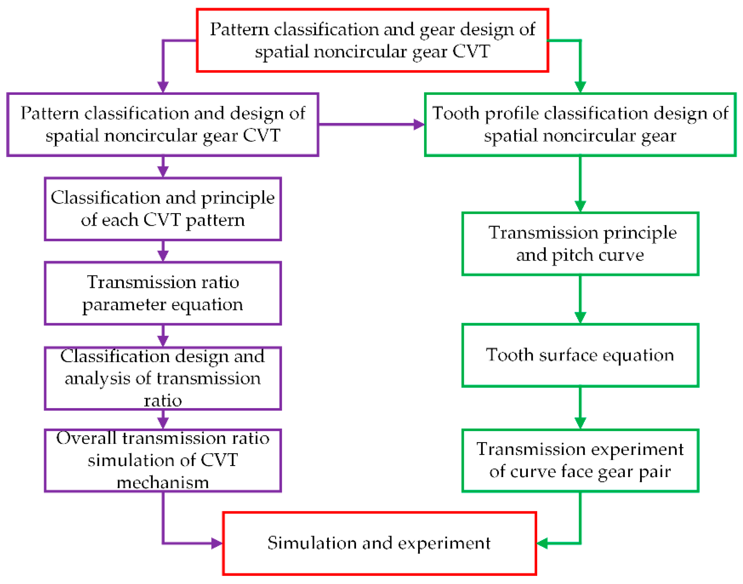
In this paper, the pattern classification and design, transmission principle, and simulation of spatial noncircular gear CVT pattern were carried out. The pitch curve, tooth surface classification design, and transmission experiment of curve face gear pairs with different tooth profiles were introduced in detail. The correctness of the pattern classification and design of spatial noncircular gear CVT was verified, with the hope of creating a certain foundation for further research and for the application of spatial noncircular gear CVT. The research process was shown in
Figure 1.
2. Pattern Classification of Spatial Noncircular Gear CVT
Spatial noncircular gear CVT pattern can be divided into two categories, with a total of five subcategories, as shown in
Table 1 and
Figure 2. Type I is the addition method, including classes A, B, and C, named NG-PBGT, NG-PCGT, and CFG-BG-PCGT, respectively. Type II is the multiplication method, including classes D and E, named CFG and NG, respectively.
In
Figure 2,
ωi and
ωo are the input and output angular velocities, respectively. The spatial noncircular gear CVT mechanism includes three parts. The first part is the phase switching mechanism, which is responsible for adjusting the phase angle between the two driving spatial noncircular gears and synchronizing their rotation speed at the same time. The second part is the transmission ratio changing part, which is responsible for integrating the transmitted variable transmission ratio to achieve a constant speed output within a certain range of input rotation angle. The third part is the transmission selection mechanism, which is responsible for selecting the transmission ratio transmitted in order to only output a constant rotation speed during the transmission. Through the transmission selection mechanisms of multiple branches, the transmission ratio of each branch at different input rotation angles was integrated, and finally a constant rotation speed output with the input rotation angle in the range of 0 to 360° was realized.
The structure of the phase switching mechanism and the transmission selection mechanism of the five patterns are the same, but the transmission ratio changing part is different. For the three classes included in type I, the transmission ratio changing part is composed of different spatial noncircular gear mechanisms and differential mechanisms. Through the addition method, the transmission ratios of gear pairs were integrated to achieve a constant speed output. For the two classes included in type II, the transmission ratio changing part is composed of different spatial noncircular gear mechanisms. Through the multiplication method, the transmission ratios of gear pairs were integrated to achieve a constant speed output. The structural composition of the transmission ratio changing part of each pattern is shown in
Table 1.
3. Principle and Classification Design of Spatial Noncircular Gear CVT
3.1. Principle of Each CVT Pattern
The principles of the five CVT patterns are described in detail later. The phase switching mechanism and transmission selection mechanism are applicable to the five patterns, so only class A was taken as an example to explain them.
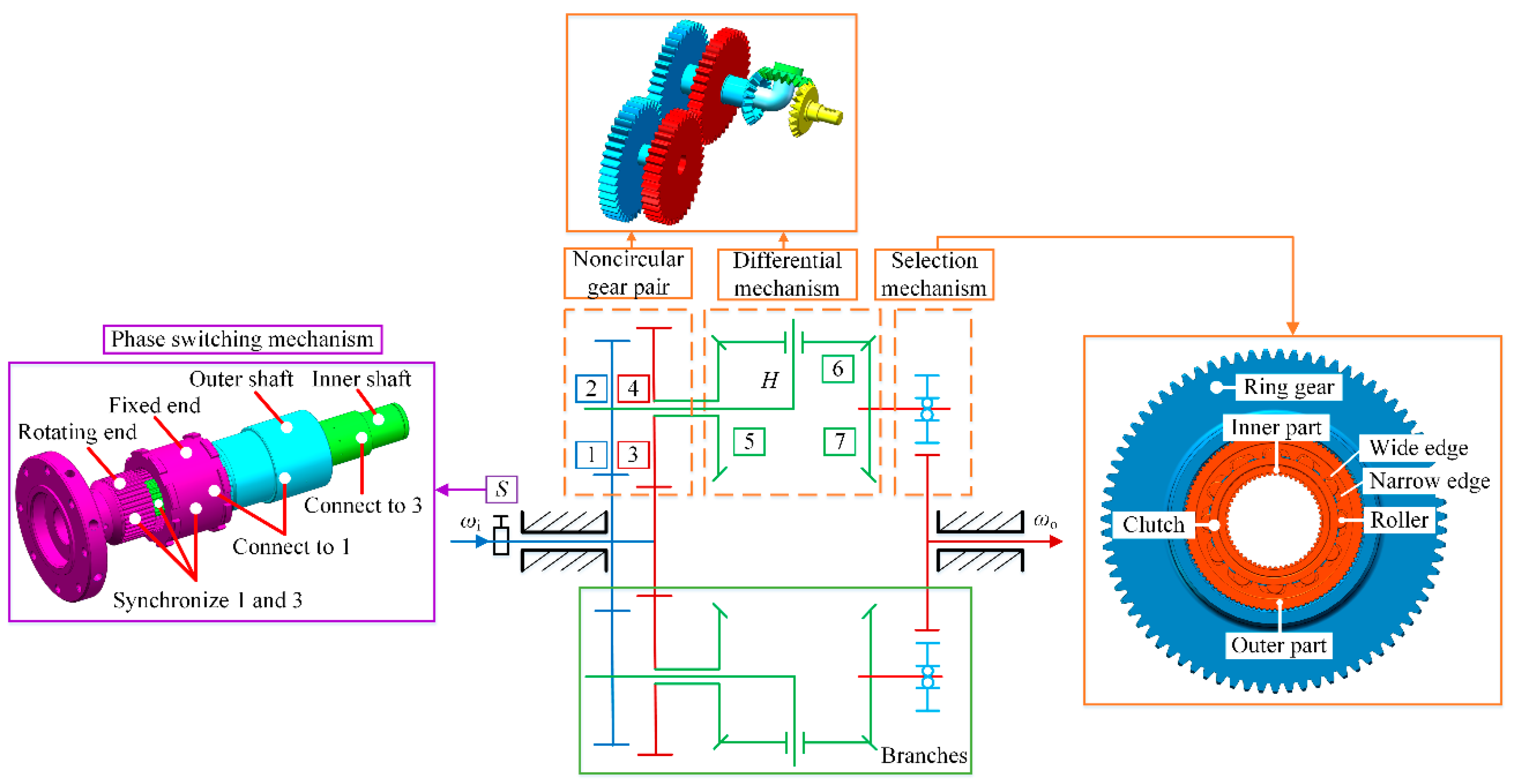
(1) Class A: NG-PBGT
Figure 3 shows the transmission principle of class A.
This mechanism includes four parts. The first part is the phase switching mechanism, which is composed of a rotating end, a fixed end, an outer shaft, and an inner shaft. The outer shaft is connected with the fixed end and the noncircular gear 1 at the same time, and the inner shaft is connected with the rotating end and the noncircular gears 3 at the same time. Step 1, by rotating the rotating end, there is a required phase angle between noncircular gears 1 and 3. Step 2, connect the rotating end with the fixed end to synchronize the rotation speed of noncircular gears 1 and 3. In steps 1 and 2, the phase angle was switched. The second part is the noncircular gear pair, which is responsible for generating the required variable transmission ratio. The third part is the differential mechanism, which is composed of a planetary bevel gear train. It is responsible for integrating the variable transmission ratios of the driven noncircular gears 2 and 4 to achieve a constant speed output within a certain range of input rotation angle. The fourth part is the transmission selection mechanism, which is composed of a clutch and a ring gear. The outer ring of the clutch is connected to the inside of the ring gear, and the outside of the ring gear is connected to the output end. The clutch only transmits one-way rotational motion. When the inner ring of the clutch rotates in one direction, the roller was driven to roll to the narrow side of the wedge groove to be clamped with the outer ring of the clutch, thereby driving the outer ring of the clutch to rotate. When the inner ring of the clutch rotates in reverse, the roller rolls to the wide edge of the wedge groove and is in a relaxed state with the outer ring of the clutch, resulting in the outer ring of the clutch not rotating. This branch does not transfer rotation at this time. By integrating the transmission ratios of multiple branches, the constant speed output with the input rotation angle in the range of 0 to 360° was realized. The CVT can be realized by continuously changing the phase angle.
In brief, the rotation speed transmission process of class A is as follows. Step 1, the input rotation speed was transmitted to the noncircular gears 1 and 3 with a certain phase angle. Step 2, the planetary bevel gear train composed of the bevel gears 5, 6, and 7 integrated the variable rotation speeds of noncircular gears 2 and 4. Step 3, the bevel gear 7 outputted a constant rotation speed within a certain input rotation angle. The planet carrier H is connected to the noncircular gear 2, and the bevel gear 5 is connected to the noncircular gear 4.
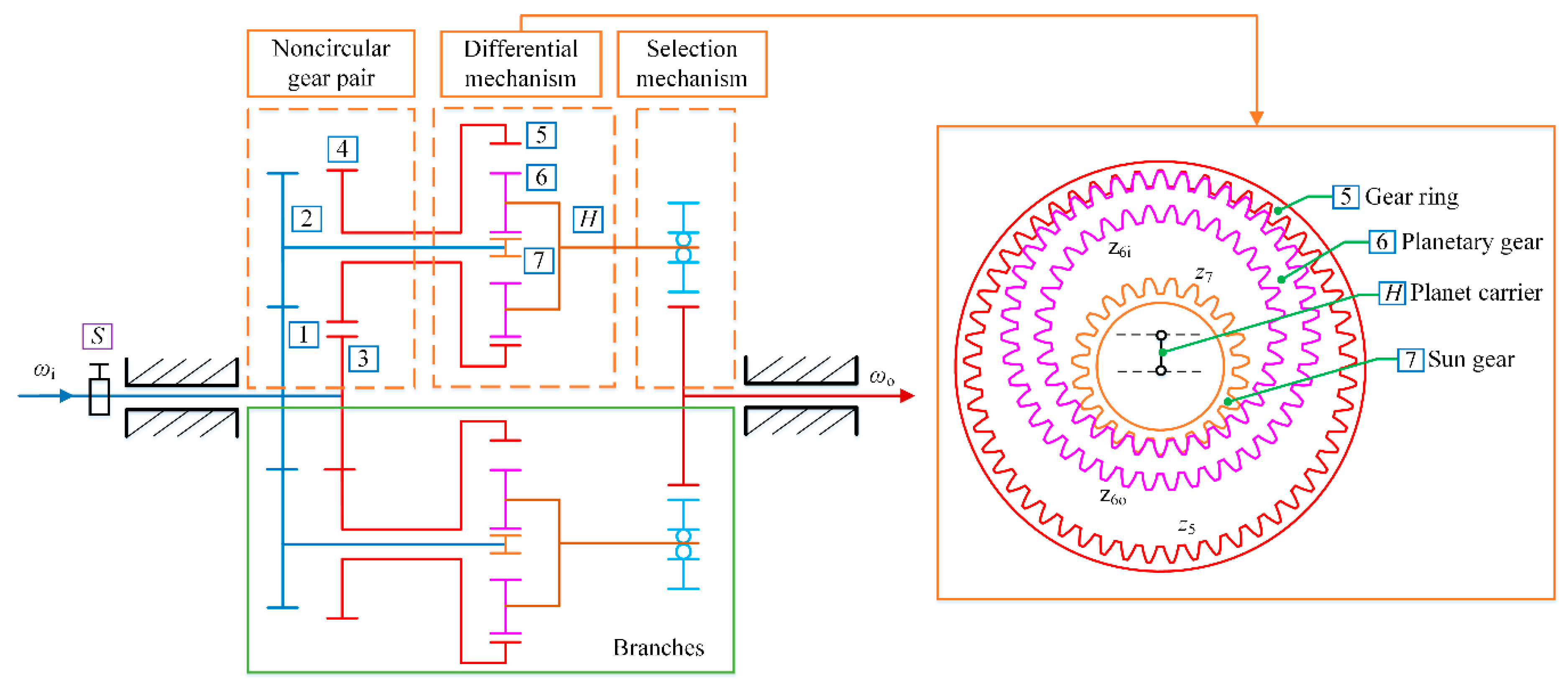
(2) Class B: NG-PCGT
Figure 4 is the transmission principle of class B, and the transmission process is as follows. Step 1, the input rotation speed was transmitted to the noncircular gears 1 and 3 with a certain phase angle. Step 2, the planetary cylindrical gear train composed of the ring gear 5, planetary gear 6, and center gear 7 integrated the variable rotation speeds of noncircular gears 2 and 4. Step 3, the planetary carrier
H outputted a constant rotation speed within a certain input rotation angle. The ring gear 5 is connected to the noncircular gear 4, and the center gear 7 is connected to the noncircular gear 2.
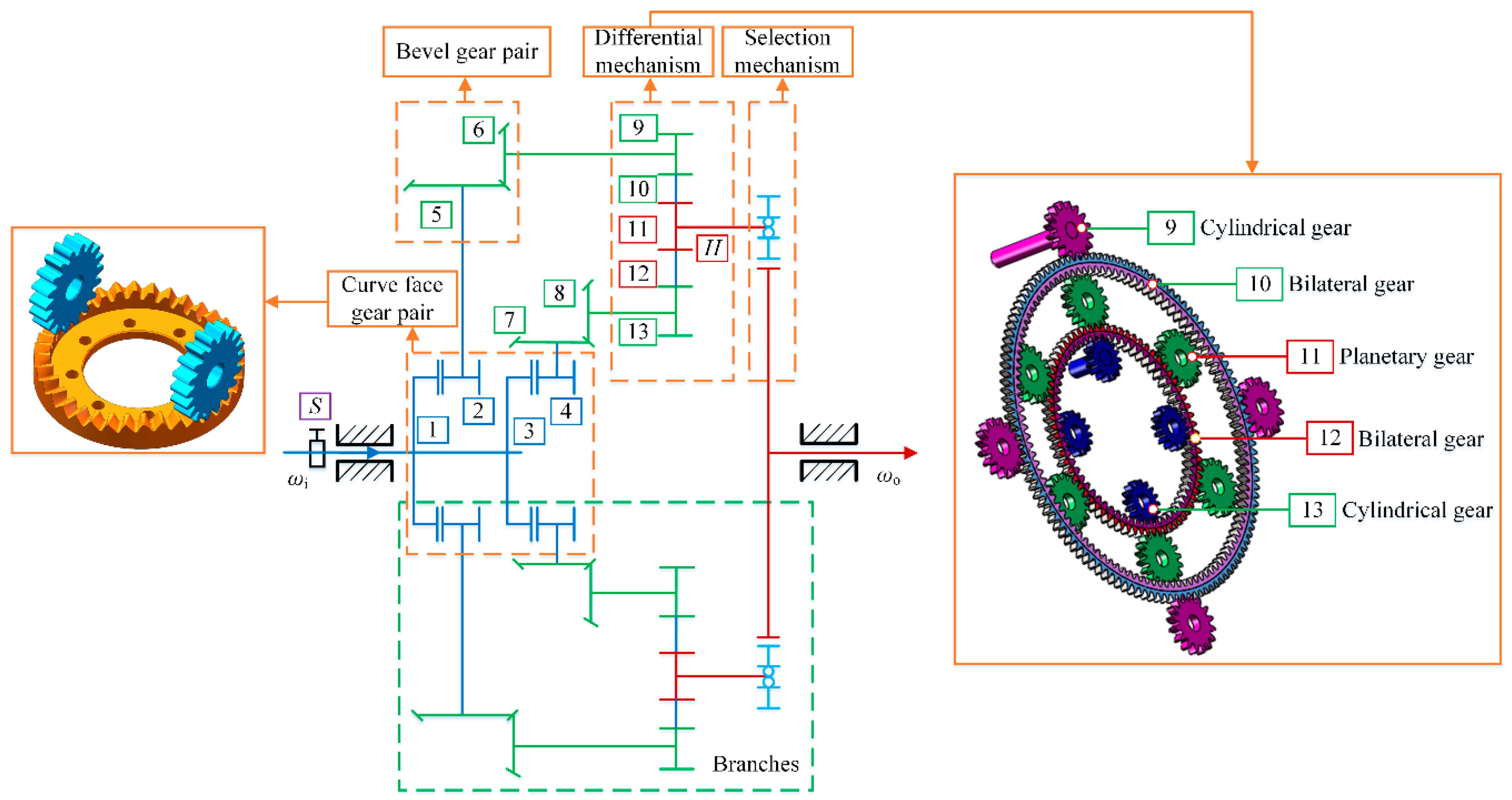
(3) Class C: CFG-BG-PCGT
Figure 5 is the transmission principle of class C. The transmission process is as follows. Step 1, the input rotation speed was transmitted to the curve face gears 1 and 3 with a certain phase angle. Step 2, two pairs of bevel gear pairs adjusted the variable rotation speed of noncircular gears 2 and 4 and changed their directions, respectively. Step 3, the planetary cylindrical gear train consisting of the cylindrical gears 9, 11, and 13 and the bilateral gears 10 and 12 integrated the rotational speeds of the bevel gears 6 and 8. Step 4, the planetary carrier
H outputted a constant rotation speed within a certain input rotation angle. The gear 9 is connected to the bevel gear 6, and the gear 13 is connected to the bevel gear 8.
(4) Class D: CFG and class E: NG
For classes D and E, the transmission principle is the same, but the difference lies in the different types of gear pairs.
Figure 6 is the transmission principle of classes D and E. In
Figure 6a, both gear pairs are curve face gear pairs. In
Figure 6b, both gear pairs are noncircular gear pairs. The transmission process is as follows. Step 1, the input rotation speed was transmitted to gear 2. Step 2, gears 1 and 3 with a phase angle integrated the variable rotation speed. Step 3, gear 4 outputted a constant rotation speed within a certain input rotation angle.
3.2. Transmission Ratio Parameter Equation
According to the analysis in
Section 3.1, the transmission ratio parameter equations of spatial noncircular gear pairs were designed, respectively, and the intermediate transmission ratio and overall transmission ratio of each pattern were calculated. See
Table 2 for each parameter equation.
In
Table 2,
θ1 and
θ3 =
θ1 +
θp are the rotation angles of gears 1 and 3 under each pattern, respectively.
θp is the phase angle.
i21 and
i43 are the transmission ratios of the corresponding gear pairs, respectively.
Ioi is the overall transmission ratio between the output shaft and input shaft.
a1,
b1,
a2, and
b2 are the parameters of the transmission ratios
i21 and
i43 of type I.
K is the characteristic parameter of the differential mechanism of type I.
a is the parameter of the transmission ratios
i21 and
i43 of type II.
For class A, z5, z6, and z7 are the teeth number of bevel gears 5, 6, and 7, respectively. i7i is the transmission ratio between the bevel gear 7 and the input shaft. Constant io7 is the transmission ratio between the output shaft and the bevel gear 7. For class B, z5 and z7 are the teeth number of the ring gear 5 and center gear 7, respectively. z6i and z6o are the number of internal teeth and external teeth of planetary gear 6, respectively. IHi is the transmission ratio between the planet carrier H and input shaft. Constant ioH is the transmission ratio between the output shaft and the planet carrier H. For class C, z9, z11, and z13 are the teeth number of the corresponding gears, respectively. z10i, z10o, z12i, and z12o are the teeth number of the inner and outer rings of the corresponding bilateral gears. iHi is the transmission ratio between the planet carrier H and input shaft. Constant ioH is the transmission ratio between the output shaft and the planet carrier H. For classes D and E, i42 is the transmission ratio between gear 4 and gear 2. Constant io4 is the transmission ratio between the output shaft and gear 4.
As can be seen from
Table 2, when the coefficient related to the rotation angle
θ1 is 0, the overall transmission ratio
ioi of each pattern is a function related only to the variable phase angle
θp. By continuously changing
θp, combined with the transmission selection mechanisms of multiple branches, the CVT with an input rotation angle in the range of 0 to 360° can be realized. The parameter conditions that each pattern need to meet were shown in
Table 3.
3.3. Classification Design and Analysis of Transmission Ratio
The transmission ratio of spatial noncircular gear pair in
Table 2 is the transmission ratio of the working area where motion and power are transmitted. In order to obtain a complete transmission ratio, a polynomial method can be used to construct the transmission ratio function of the transition area where only motion is transmitted but no power is transmitted, and the periodic transmission ratio was obtained. Taking noncircular gears 1 and 2 as examples, the transmission ratio equation is shown in Equation (1), and the transmission ratios of other spatial noncircular gear pairs can be obtained in the same way.
where,
i01(
θ1) is the transmission ratio in the working area.
i02(
θ1) is the transmission ratio in the transition area.
mj is the polynomial coefficient. Φ is the maximum rotation angle of noncircular gear 1 in the working area.
U = 2π/
n1 is the period of the transmission ratio, and the positive integer
n1 is the order of noncircular gear 1.
According to Equation (2), the unknown parameters in
i21(
θ1) can be solved.
where the positive integer
n2 is the order of noncircular gear 2.
i′
01(
θ1),
i″
01(
θ1),
i′
02(
θ1), and
i″
02(
θ1) are the first and second derivatives of
i01(
θ1) and
i02(
θ1) with respect to
θ1, respectively.
According to the above analysis, take the parameters in
Table 4 and analyze the transmission ratio of each pattern, as shown in
Figure 7 and
Figure 8.
ni is the number of cycles of the input gear and
nl is the number of branches.
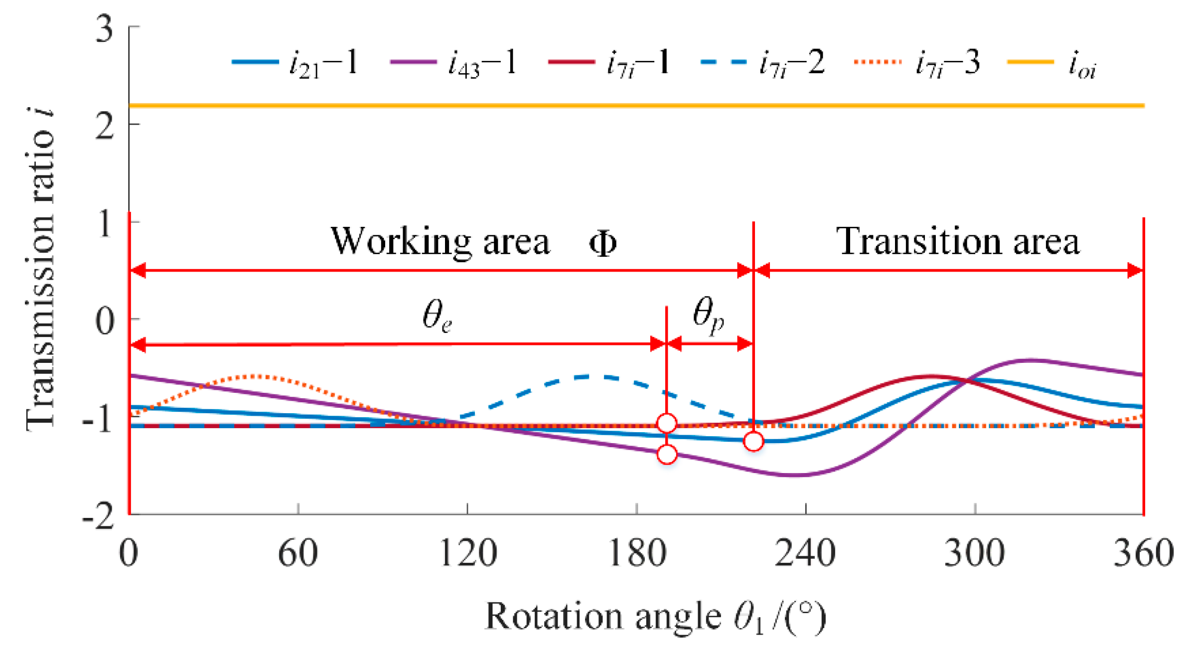
Figure 7 is the variation law of the transmission ratio of class A.
θe = Φ −
θp is the length of the effective working area, that is, the area where each branch outputs a constant rotation speed. To achieve a constant rotation speed output with an input rotation angle in the range of 0 to 360°, Equation (3) must be satisfied.
where
θemin = 2π/(
ni∙
nl) is the minimum length of the effective working area.
In
Figure 7,
i21-1, and
i43-1 are the transmission ratios of the corresponding gear pairs in the first branch, respectively.
i7i-1,
i7i-2, and
i7i-3 are the transmission ratios between the bevel gear 7 and the input shaft in the three branches, respectively. Here, Φ is 220°,
θp is 30° and
θe is 190°. As can be seen, by integrating the transmission ratios
i21 and
i43 in the three branches, respectively,
i7i-1,
i7i-2, and
i7i-3 are constant in a certain area. Specifically,
i7i -1 is constant when
θ1 varies from 0 to 190°.
i7i-2 is constant when
θ1 varies in the range 0~70° and 240~360°.
i7i-3 is constant when
θ1 varies in the range 120~310°. Finally, by integrating the transmission ratios
i7-1,
i7i-2, and
i7i-3, the overall transmission ratio
ioi is always constant when
θ1 varies from 0 to 360°.
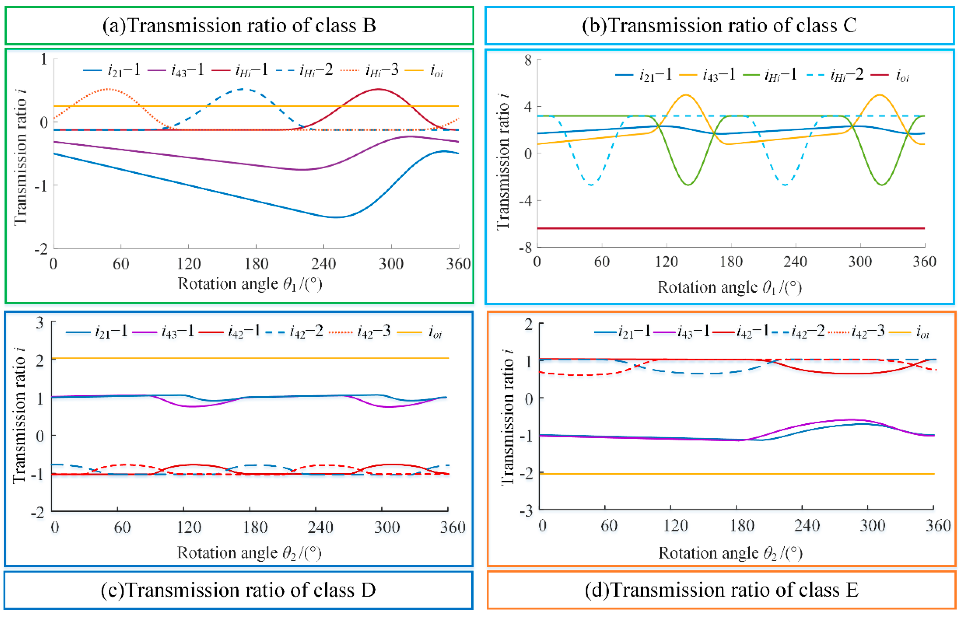
Figure 8 shows the variation law of the transmission ratios of classes B~E.
In
Figure 8,
i21-1, and
i43-1 are the transmission ratios of the corresponding gear pairs in the first branch, respectively.
ioi is the overall transmission ratio between the output shaft and input shaft. In
Figure 8a,b, the input rotation angle is
θ1.
iHi-1,
iHi-2, and
iHi-3 are the transmission ratios between the planet carrier
H and input shaft in each branch, respectively. In
Figure 8c,d, the input rotation angle is
θ2.
i42-1,
i42-2, and
i42-3 are the transmission ratios between gear 4 and gear 2 in the three branches, respectively. Similarly, the maximum working angle
Φ of class B~E are 220°, 100°, 110°, and 200°. The phase angle
θp of class B~E are 30°, 10°, 30°, and 30°. The length of the effective working area
θe of class B~E are 190°, 90°, 80°, and 170°. By integrating the transmission ratios
i21 and
i43 of each branch, respectively,
iHi and
i42 of each branch are constant in a certain area. Finally, through the integration of the transmission ratios of multiple branches, each pattern can achieve a constant rotation speed output throughout the area. CVT can be realized by continuously changing the phase angle.
5. Simulation and Experiment
Since the main difference between the five patterns is the transmission ratio changing part, and its complex key components are the curve face gear pair, the overall transmission ratio of each pattern was verified by simulation, and the transmission ratio of the curve face gear pair was verified by experiment.
5.1. Overall Transmission Ratio Simulation of CVT Mechanism
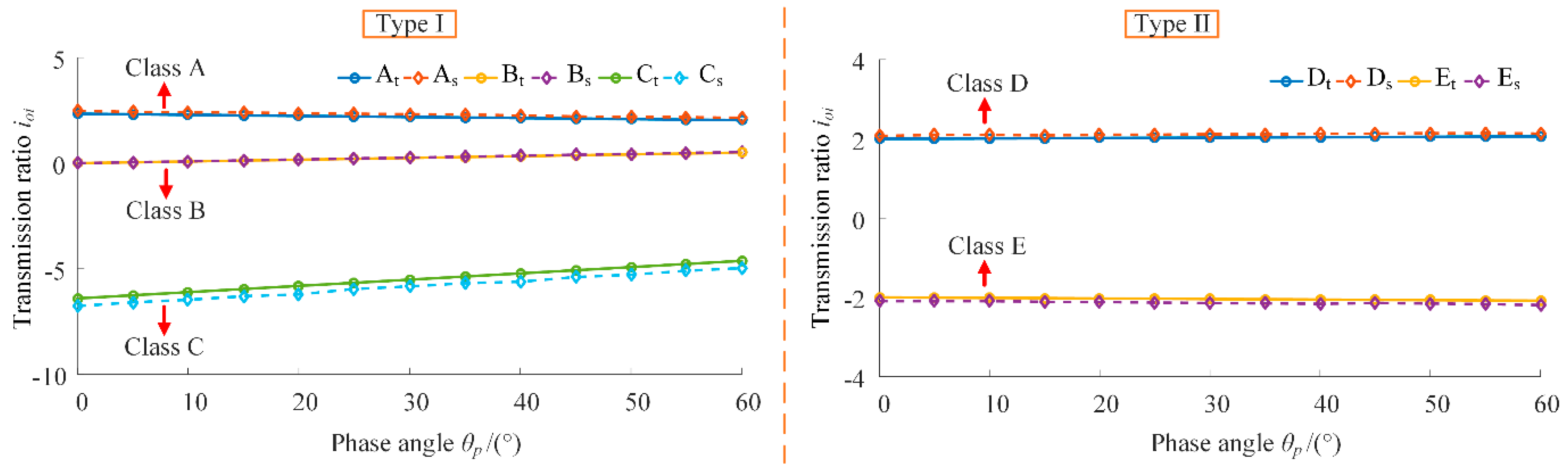
The mechanism models of five patterns were imported into the software ADAMS, and then the overall transmission ratios with different phase angles were simulated. Taking the phase angle in the range of 0 to 60° as an example, the comparison between the theoretical and simulation results was shown in
Figure 15.
In
Figure 15, A
t, B
t, C
t, D
t, and E
t are the theoretical results of the overall transmission ratio of each pattern, respectively. A
s, B
s, C
s, D
s, and E
s are the simulation results of the overall transmission ratio. As can be seen, the overall transmission ratio values of classes A, B, and D are no less than 0, which means that the output shaft turns in the same direction as the input shaft. The overall transmission ratio values of classes C and E are less than 0, which means that the output shaft turns in the opposite direction as the input shaft. Moreover, for classes A and C, the absolute values of
ioi gradually decrease with the increase of phase angle
θp. For classes B, D, and E, the absolute values of
ioi gradually increase with the increase of phase angle
θp. Further, for classes A, B, and C, the overall transmission ratio
ioi can be zero by selecting the appropriate parameters. At this time, no matter what the input rotation speed is, the output rotation speed is zero. However, for classes D and E, due to the limitation of transmission ratio principle, the overall transmission ratio
ioi cannot be zero. On the whole, the simulation results are in good agreement with the theoretical results, and the overall transmission ratio changes continuously with the continuous change of the phase angle, that is, the CVT was realized.
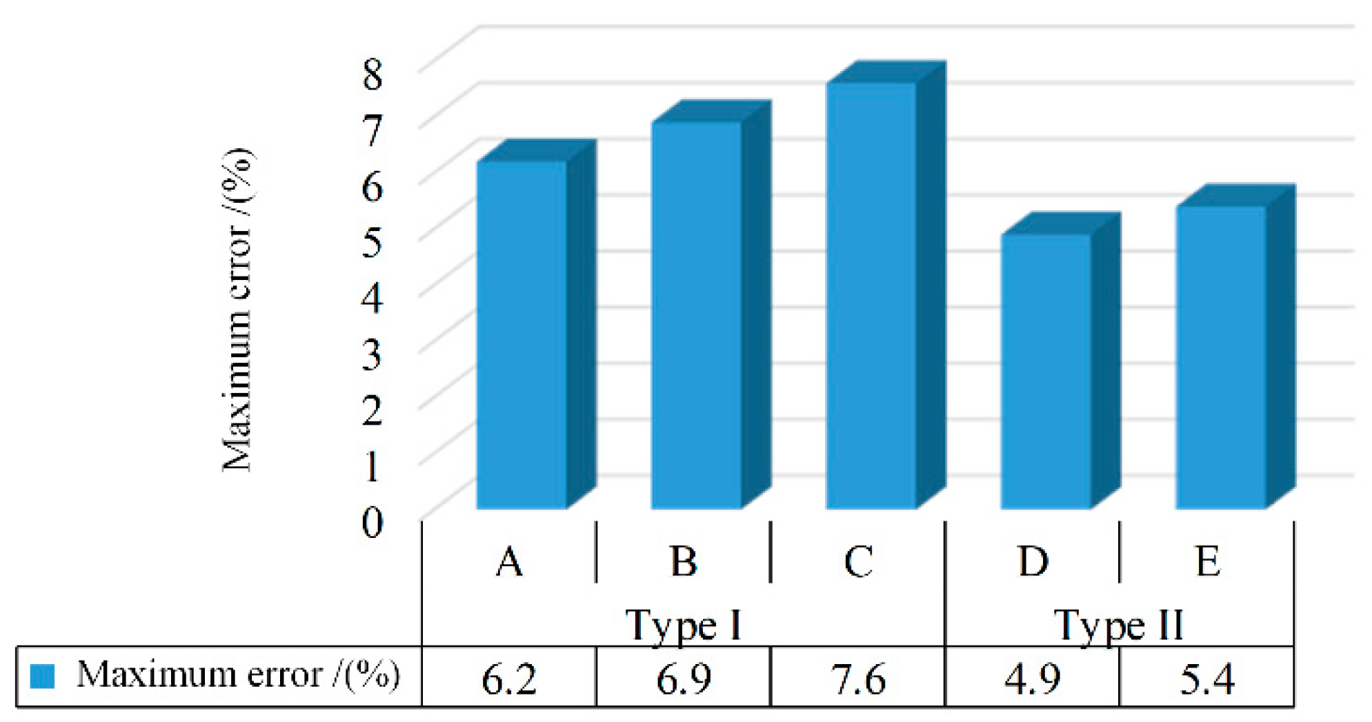
Figure 16 shows the maximum relative error of overall transmission ratio simulation for each pattern. For classes A~E, the maximum relative errors are 6.2%, 6.9%, 7.6%, 4.9%, and 5.4%. The reason why the error of type I is greater than that of type II is that the structure of type I mechanism is more complex, and the transmission chain is longer, resulting in greater transmission ratio loss and transmission ratio error.
In summary, the CVT mechanism characteristics of types I and II were shown in
Table 5.
The type I mechanism has the advantages of simple design, larger transmission ratio range, and less parameter restrictions, while the type II mechanism has the advantages of simple structure, small volume, and shorter transmission chain.
5.2. Transmission Experiment of the Curve Face Gear Pair
In order to verify the correctness of the tooth profile classification design of the curve face gear pair, a transmission experiment is needed. Taking the first pair of the curve face gear pairs in class C as an example, the parameters in
Table 4 and
Table 6 were selected to obtain the curve face gear pairs with three different tooth profiles by 5-axis CNC milling.
Figure 17 shows the transmission experiment of the curve face gear pair. The input rotation speed is 200 rpm, and the load is 50 N·m. The rotation speeds of the input shaft and output shaft were measured by torque-speed sensor JN338 (produced by Beijing Sanjing Creation Science and Technology Group Co., Ltd., Beijing, China) and torque-speed sensor DRFL-VI-500-A-K (produced by ETH-MESSTECHNIK), respectively, and the transmission ratios of three kinds of curve face gear pairs were calculated.
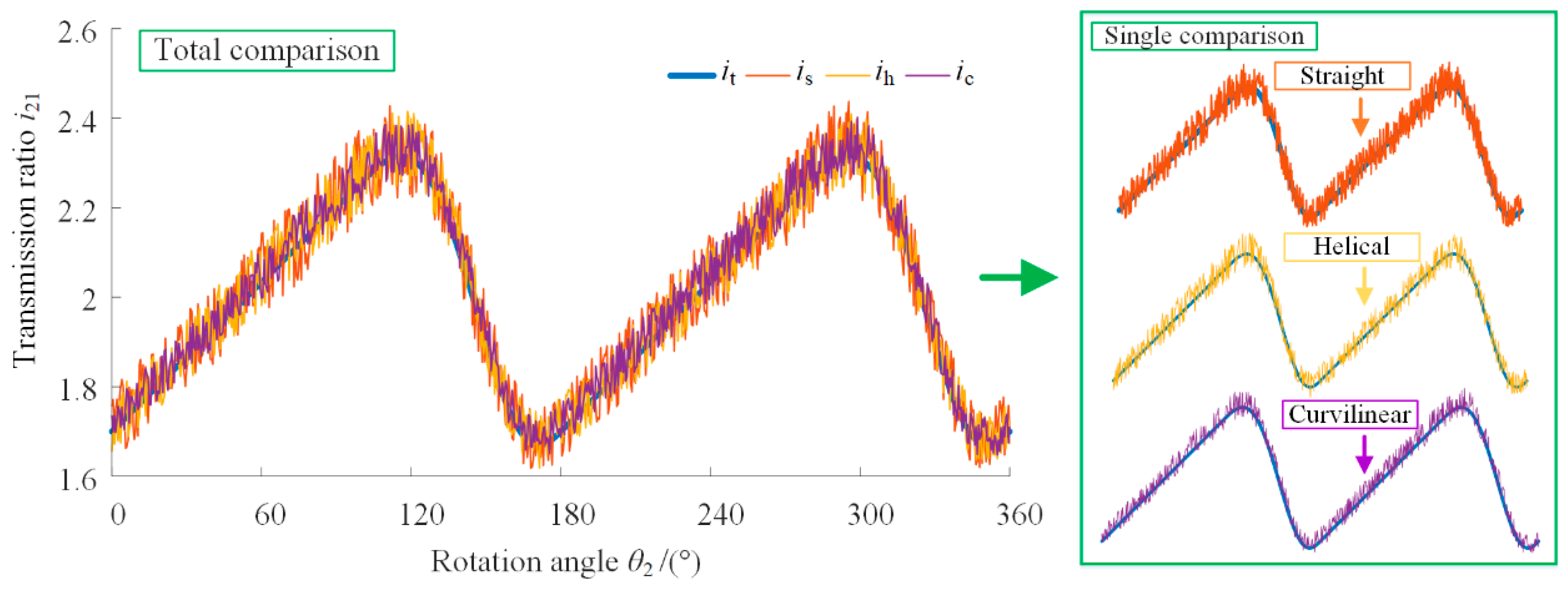
The experimental transmission ratios were compared with the theoretical transmission ratios, as shown in
Figure 18.
it is the theoretical curve of transmission ratio.
is,
ih and
ic are the measured curves of transmission ratios of curve face gear pairs with straight tooth, helical tooth, and curvilinear tooth, respectively. As can be seen, when the rotational angle
θ2 varies from 0 to 360°, the transmission ratio
i21 varies in the range of 1.6~2.4, and the number of cycles of
i21 is 2. Moreover, as can be seen from the total comparison and single comparison, the three measurement curves of the transmission ratio are in good agreement with the theoretical curve, which indicated the correctness of the theoretical method.
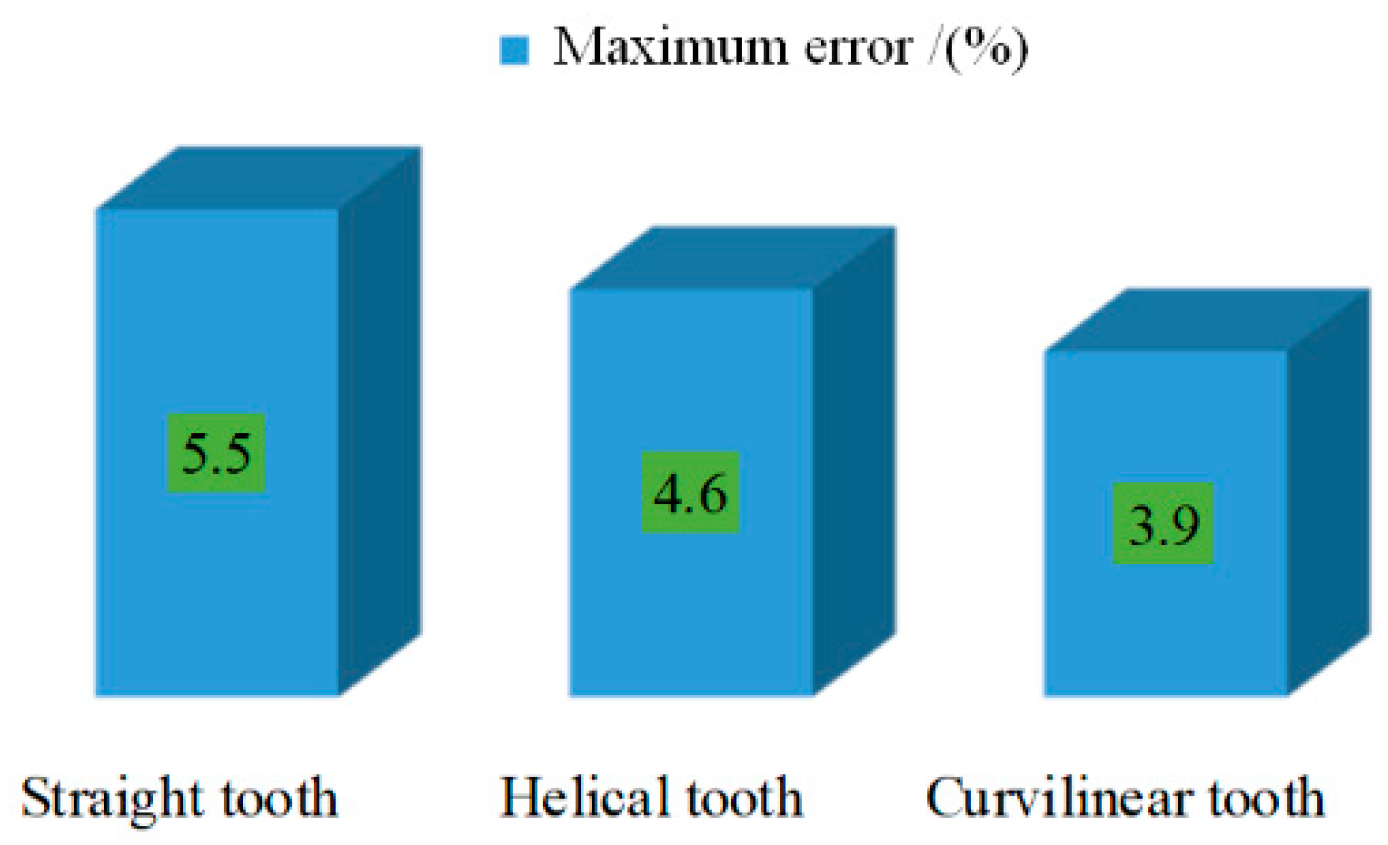
Figure 19 shows the maximum relative error of the transmission ratio experiment.
The experimental curves of the transmission ratios of the three curve face gear pairs are close to the theoretical curve, and the matching degree from low to high is the transmission ratio curve of the straight tooth, helical tooth, and curvilinear tooth curve face gear pair, respectively. The maximum relative errors of the corresponding transmission ratios are 5.5%, 4.6%, and 3.9%, respectively. The main reason for this difference is that the tooth profile has an important influence on the transmission stability of the curve face gear pair. The curvilinear tooth transmission is the most stable, followed by the helical tooth, and finally the straight tooth.
Besides, the causes of experimental errors mainly include machining errors, installation errors, and measurement errors. Considering the influence of the above errors, the experimental errors were within a reasonable range. The correctness of tooth profile classification design method was verified by the transmission experiment of curve face gear pair, which laid a foundation for the further research of CVT mechanism.
6. Conclusions
Through the study of pattern classification and gear design of spatial noncircular gear CVT, the following conclusions can be drawn.
(1) Under the condition of choosing appropriate parameters, all the five patterns can realize the CVT. Compared with type I, type II has the advantages of a simpler structure, smaller volume, shorter transmission chain, and higher transmission efficiency. However, it is more complex in design, relatively limited by parameters and has a smaller range of transmission ratio. According to the actual working situation and requirements, different patterns can be selected to realize the required CVT;
(2) The curve gear face pair can realize variable transmission ratios between intersecting shafts. Through the tooth profile classification design method, the curve face gear pairs with straight tooth, helical tooth, and curvilinear tooth can be obtained. Compared with the straight tooth curve face gear pair, the helical tooth and curvilinear tooth curve face gear pair have a more complex design, but a greater contact ratio and load capacity, which can meet the requirements of different working situations;
(3) The overall transmission ratio of each pattern was simulated, and the simulation errors were within a reasonable range, which verified the correctness of the theoretical analysis of each pattern. Through transmission experiments, the correctness of the tooth profile classification design method of the curve face gear pair was verified, which provided a strong proof for the correctness of the whole design method to a certain extent;
(4) The CVT principle and transmission ratio characteristics of each pattern were analyzed only from the aspect of kinematics here. However, the dynamic characteristics and performance of each pattern should be further studied in the follow-up work, such as vibration, noise, carrying capacity, and transmission efficiency, which have an important impact on the working performance of the spatial noncircular gear CVT system.


