1. Introduction
Today, modern optical instruments are widely used for industrial, measurement, laser, and manufacturing systems. An optical lens is one of the key components of the system that focuses or disperses a light beam. The position of the lens axis determines the focal point. Therefore, it is important to align the lens axis properly. Usually, optical lenses are fixed in the holders, so the centering of the lens axis to the holder axis determines the precision of the optical system. Proper position of the lens in the holder allows obtaining the focal point in the required position and to achieve required characteristics of the optical system.
The assembly process of the lens and holder requires a mechanical system that can provide 2-DOF planar and 3-DOF angular motions to move the lens into the center of the holder and rotate it so that axis of the lens would coincide with the holder axis. Usually, the position of the lens in the holder is adjusted using a micrometric resolution positioning system with several actuators and motors, because most of the actuators and motors are single degrees of freedom devices [
1,
2,
3]. Therefore, two or more devices must be combined to obtain several degrees of freedom system. However, such compound systems have a complicated structural design, and motion control is implemented using complex driving and control electronics. Moreover, synchronization of several high-precision devices is a challenging task that affects the accuracy and reliability of the entire positioning or manipulation system [
4,
5].
Therefore, multi-degree-of-freedom actuators and motors must be developed that will meet the requirements of the modern positioning systems. Usually, electromagnetic actuators and motors are employed to move payloads at different speeds and resolutions. However, these types of motor are unable to provide motion of several degrees of freedom. Also, the resolution of motion is limited [
6]. Moreover, technological aspects limit the miniaturization of electromagnetic actuators and motors, while the electromagnetic field induces additional motion errors because of remnant magnetization [
7,
8,
9,
10]. Therefore, scalable, high-resolution, several-degrees-of-freedom actuators and motors must be developed to overcome the aforementioned disadvantages, and piezoelectric systems are a reasonable option [
6,
11,
12,
13,
14,
15,
16]. The state of the art of several degrees of freedom piezoelectric actuators, motors, and robots that provide planar or angular motion is given below in this section.
Liu et al. reported on a milli-size robot developed for planar motion [
17]. The robot has three identical piezoelectric legs consisting of eight pieces of piezo ceramic. The planar motion of the robot is generated by imitating arthropod-metamerism motion that is induced by the exciting bending vibration of the legs. The robot can provide bi-directional planar motion and perform steering as well as generate rotation motion around the main axis of the robot. Numerical and experimental investigations showed that the robot achieves a planar speed of 516.3 mm/s and a resolution of 0.44 μm when a payload of 200 g is applied. However, the authors did not consider the possibility to generate angular motion of the payload.
Niu and Guo introduced a piezoelectric planar motion robot with multiple degrees of freedom [
18]. The robot consists of a rectangular bronze plate with a trapezoidal cross-section and eight piezo ceramic plates glued on a bronze plate. Four driving feet are used to move the robot. The operation of the robot is based on the excitation of four different vibration modes. Linear motion of the robot is induced employing superposition of the first order longitudinal and third-order bending modes while superposition of the second-order in-plane and out-of-plane bending modes are used to control motion direction and achieve rotation of the robot about the
Z-axis. The robot achieves a maximum linear speed of 37 mm/s and rotation speed of 6.28 rad/s. However, the robot cannot rotate and move the payload in the plane independently.
Zang et al. proposed a two-DOF piezoelectric rotary motor [
19]. The design of the motor is based on a flat cross-shaped actuator and a cylinder placed at the center of the actuator. The spherical rotor is placed on top of the cylinder using an additional positioning frame. The operation principle is based on an inertial stick-slip principle. It was shown that the motor can achieve a rotation speed around
X and
Y axes up to 268.48 mrad/s and resolution of 6.34 μrad. However, the actuator provides only 2-DOF angular motion of payload, while the planar motion of the payload was not foreseen.
Wang et al. introduced a piezoelectric 3-DOF rotary motor [
20]. The design of the motor is based on four piezoelectric beams joined in a cross-shaped structure. The spherical rotor is placed in the center of the cross structure. The operation principle of the motor is based on the excitation of longitudinal and bending modes of the beams using harmonic electric signals with a phase difference. Numerical and experimental investigations showed that the rotor can be rotated around the
X and
Y axes with a speed of 363 RPM, while the rotation speed around the
Z-axis was 171 RPM.
Literature review showed that there are no piezoelectric robots developed using a single actuator that can provide planar and rotational motion. On the other hand, few dual-function piezoelectric actuators and motors are proposed [
21,
22]. However, in most cases, these devices can provide angular and planar motion of the cylinder-shaped slider [
23,
24].
This paper represents a novel 5-DOF piezoelectric robot that can provide unlimited 2-DOF planar motion and 3-DOF angular motion of the payload independently. The main advantages of the proposed robot are unlimited planar motion, simple design based on a single piezoelectric transducer, and angular and planar motions of the robot are controlled using a single excitation signal. The proposed piezoelectric robot can be used for optical lens positioning in the holder.
2. Design and Operation Principle of Robot
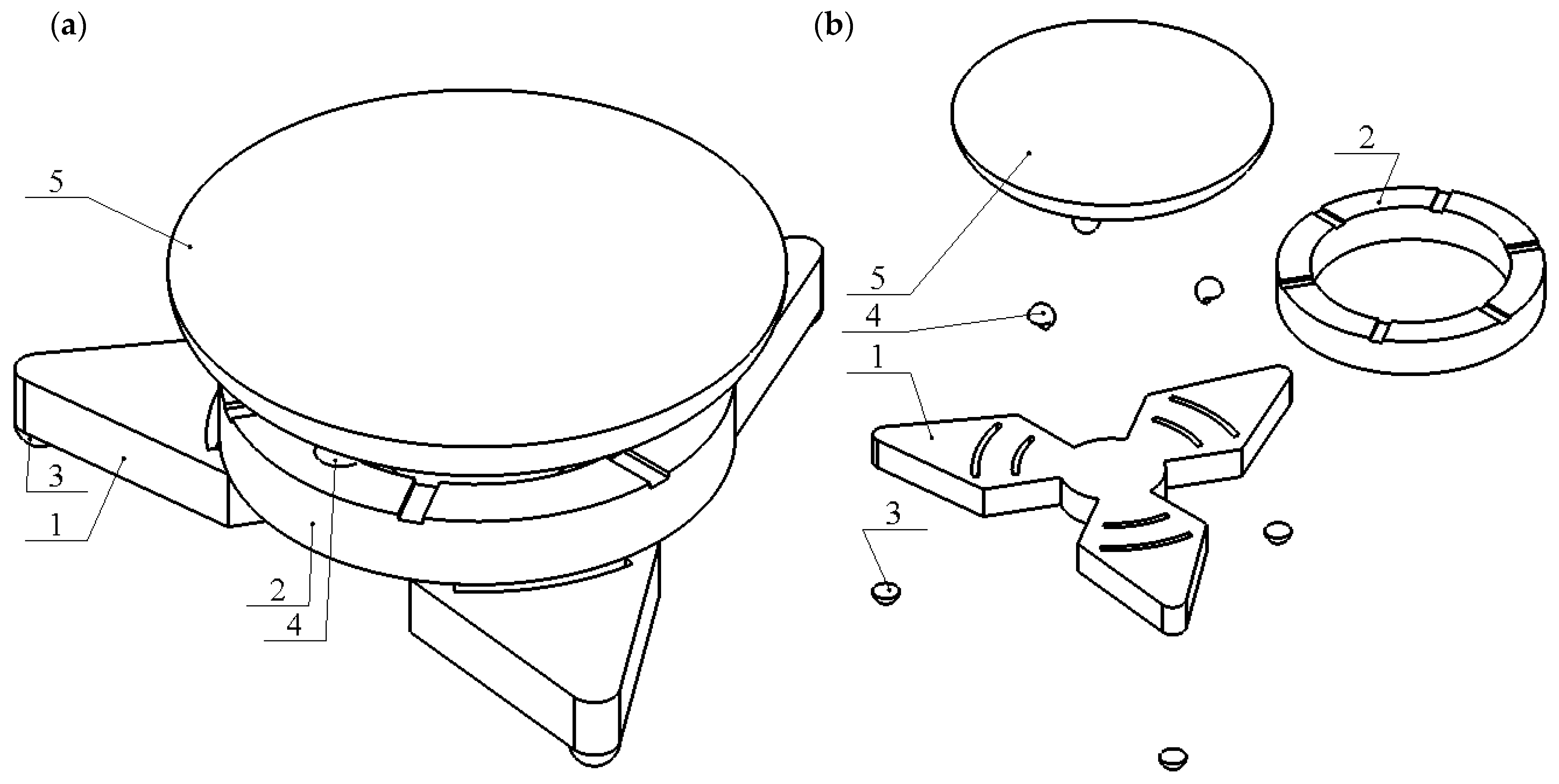
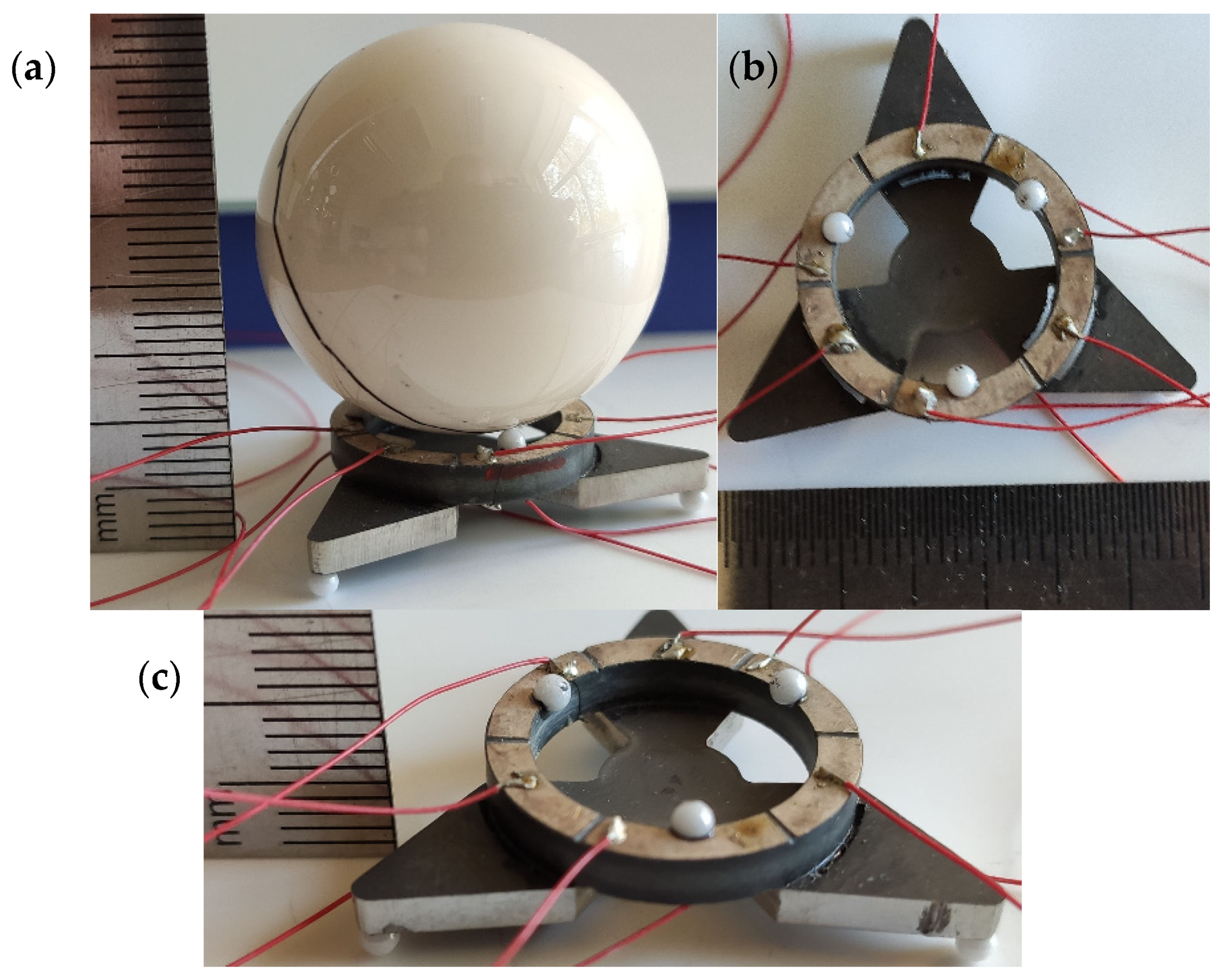
The robot consists of a triangular-shaped passive layer made from stainless steel and a piezo ceramic ring glued on top of the passive layer (
Figure 1). The passive layer consists of three trapezoidal cantilevers joined in the center of the structure. Piezoceramic ring is made from hard type ceramic PIC181 (PI Ceramics, Lederhose, Germany). The top electrode of the piezo ceramic ring is divided into six equal segments that are used to control planar and angular motions. The ring is in contact with the passive layer only at the bases of trapezoidal cantilevers, while the other three segments of the piezo ceramic ring are free from the passive layer. In addition, each trapezoidal cantilever has cuts near the piezo ceramic ring that were made to reduce the vibrations coupling between different segments of the piezo ceramic ring and trapezoidal cantilever. Alumina oxide semispherical contacts are glued at the end of each trapezoidal cantilever and are in contact with the plane used for the planar locomotion of the robot. Three additional semispherical contacts are placed on the top of the ring and are used to place the payload on the robot and rotate it. Vibrations of the particular contact are excited by the corresponding section of the piezoceramic ring.
The geometrical parameters of the robot are shown in
Figure 2. The volume of the presented piezoelectric robot is 2.69 cm
3, while the total weight without payload is 12.92 g. The robot occupies an area of 310 mm
2. The payload can have a spherical or flat surface. The payload is moved in the plane when it has a flat contacting surface, and rotated when the surface is spherical. Later in this paper, the only rotational option of the spherical payload will be analyzed. The planar locomotion of the robot is limited only by the size of the manipulation surface.
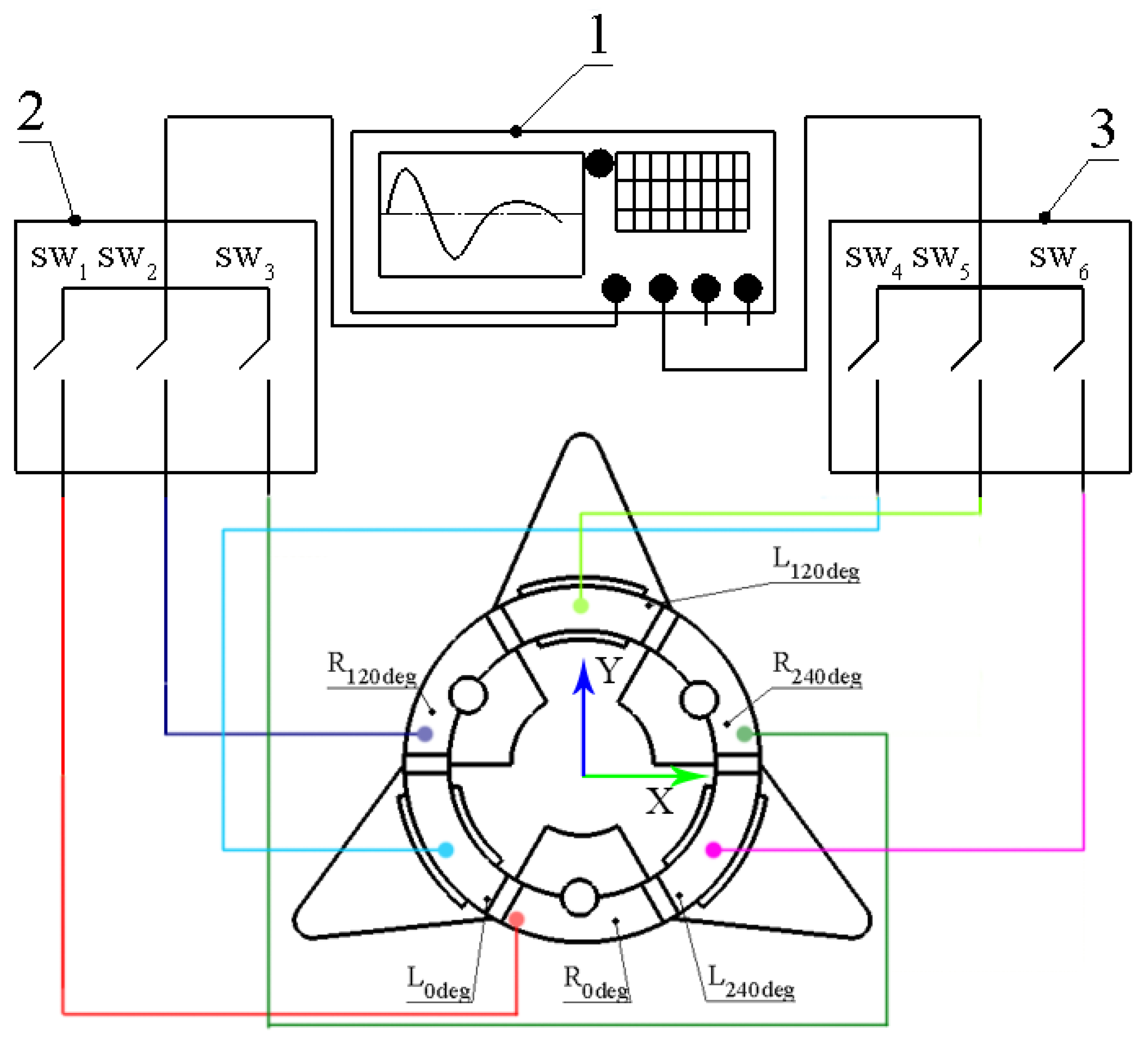
The operation principle of the robot is based on the excitation of the third radial vibration mode of the ring and the first bending mode of the trapezoidal-shaped cantilever. The radial mode of the ring is used to induce rotation of the payload, while the bending mode of the cantilever generates planar locomotion of the robot. Control of planar and rotational motions can be implemented using two digitally controlled switch boxes and two harmonic electric signals where the first signal is used to obtain planar motion and the second rotational motion. Excitation schematics of the robot are given in
Figure 3.
Planar locomotion of the robot is obtained when a harmonic signal with a frequency of the first bending mode of the trapezoidal cantilever is applied to segment L0deg, L120deg or L240deg. The selection of the segment depends on the needed motion direction of the robot. Contraction and extraction of the ring segment excite the first bending mode of trapezoidal cantilever, and the semispherical contact impacts the manipulation surface and in this way generates planar locomotion of robot. Reverse motion is obtained by applying the same harmonic signal to the other two segments of the piezoceramic ring. Because of the different stiffness obtained via uneven contact between piezo ceramic ring and cuts made at the passive layer, vibrations of contact generated by an activated segment have low coupling with the vibrations of other semispherical contacts. Therefore, the vibrations of these contacts have a minor effect on the needed direction of planar or angular motions.
The rotational motion of the payload around the X or Y axis is obtained in a similar way, i.e., by applying a harmonic signal with a frequency of the third radial mode of the piezoceramic ring to segment R0deg, R120deg, or R240deg. Radial vibrations of the segment make impacts to the spherical surface of the payload, and angular motion of the payload is generated. Reverse motion is obtained when the same harmonic signal is applied to two opposite ring segments. Moreover, to obtain rotation around the Z-axis, three harmonic signals with a phase difference of 120° should be applied to all segments R0deg, R120deg, or R240deg.
Different trajectories of robot locomotion and payload rotation can be obtained via the commutation of two harmonic signals with different frequencies using two digitally controlled switch boxes (
Figure 3, 2,3). Switch box control signals and corresponding motion directions are given in
Table 1.
3. Numerical Investigation of Robot
A numerical investigation of the robot was performed to analyze the electrical and mechanical characteristics as well as vibrations of the contacts and coupling ratios between vibrations. A numerical model was built using Comsol 5.4 software. The geometric parameters of the robot are shown in
Figure 2. Material characteristics were defined as follows: DIN 1.4301 stainless steel was used for the passive triangle layer, the piezoceramic PIC 181 (PI Ceramics) was used for the ring, and finally, alumina oxide material properties were used for semispherical contacts. The material properties used to build the model are given in
Table 2.
The payload was simulated as a distributed mass placed on the contacts located on top of the piezoceramic ring. The gravity force of the robot was included in the model. Electric boundary conditions were defined depending on the study and are given below in this section. The excitation schematic of the robot is shown in
Figure 3.
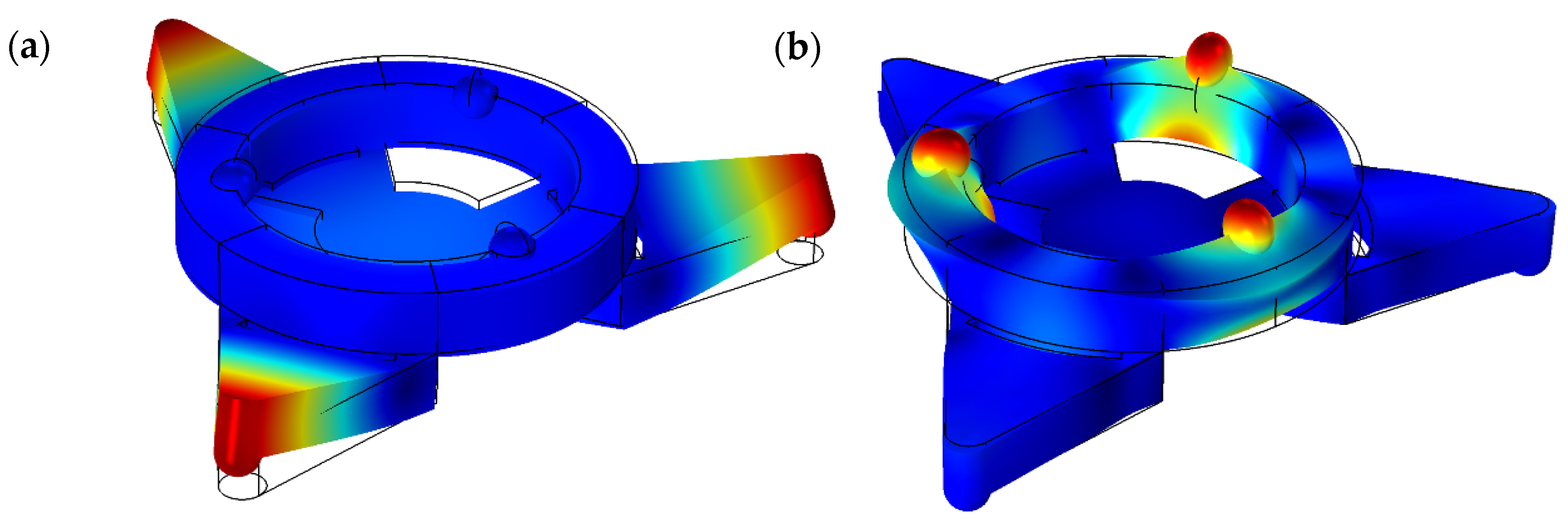
Firstly, a modal analysis of the robot was performed. The goal of the study was to indicate vibration modes and natural frequencies suitable for robot operation. The electrical boundary condition of the piezoceramic ring was set to obtain a short circuit status. Modal shapes of the actuator are shown in
Figure 4.
Figure 4a shows that the first bending mode of trapezoidal cantilevers occurs at the frequency of 13.79 kHz. It can be seen that the highest displacement amplitudes are obtained at the ends of the cantilevers, while contacts used for angular motion have very small displacements. Therefore, forced vibrations of trapezoidal cantilevers will have a minor influence on the vibration of contacts located on the top of the ring. The third radial vibration mode of the piezo ceramic ring is obtained at a frequency of 95.75 kHz. Analyzing this mode, it can be seen that radial vibrations of the piezo ceramic ring have a minor influence on vibrations of trapezoidal cantilevers. Therefore, the angular position of the payload will not generate planar motion of the robot.
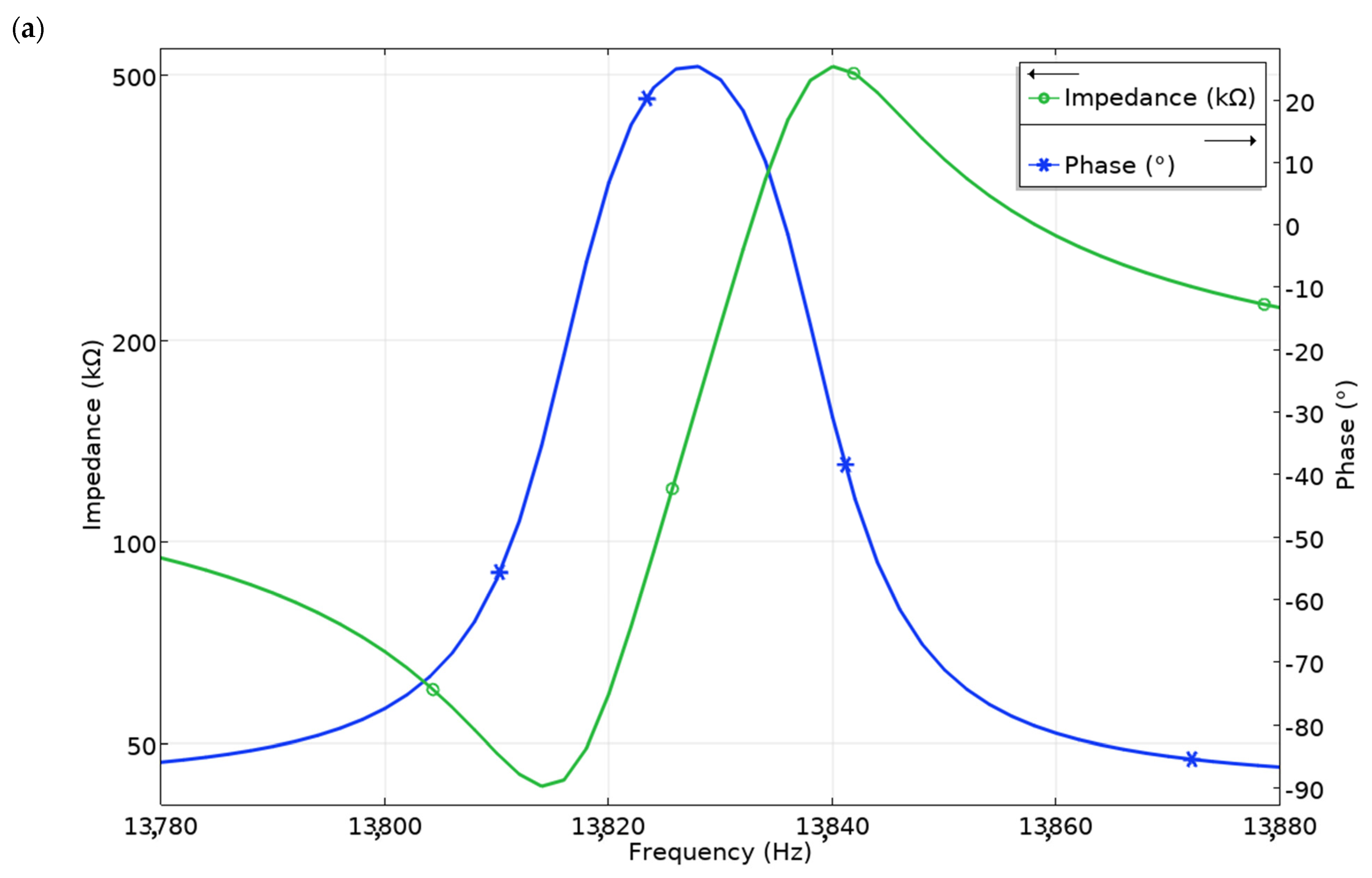
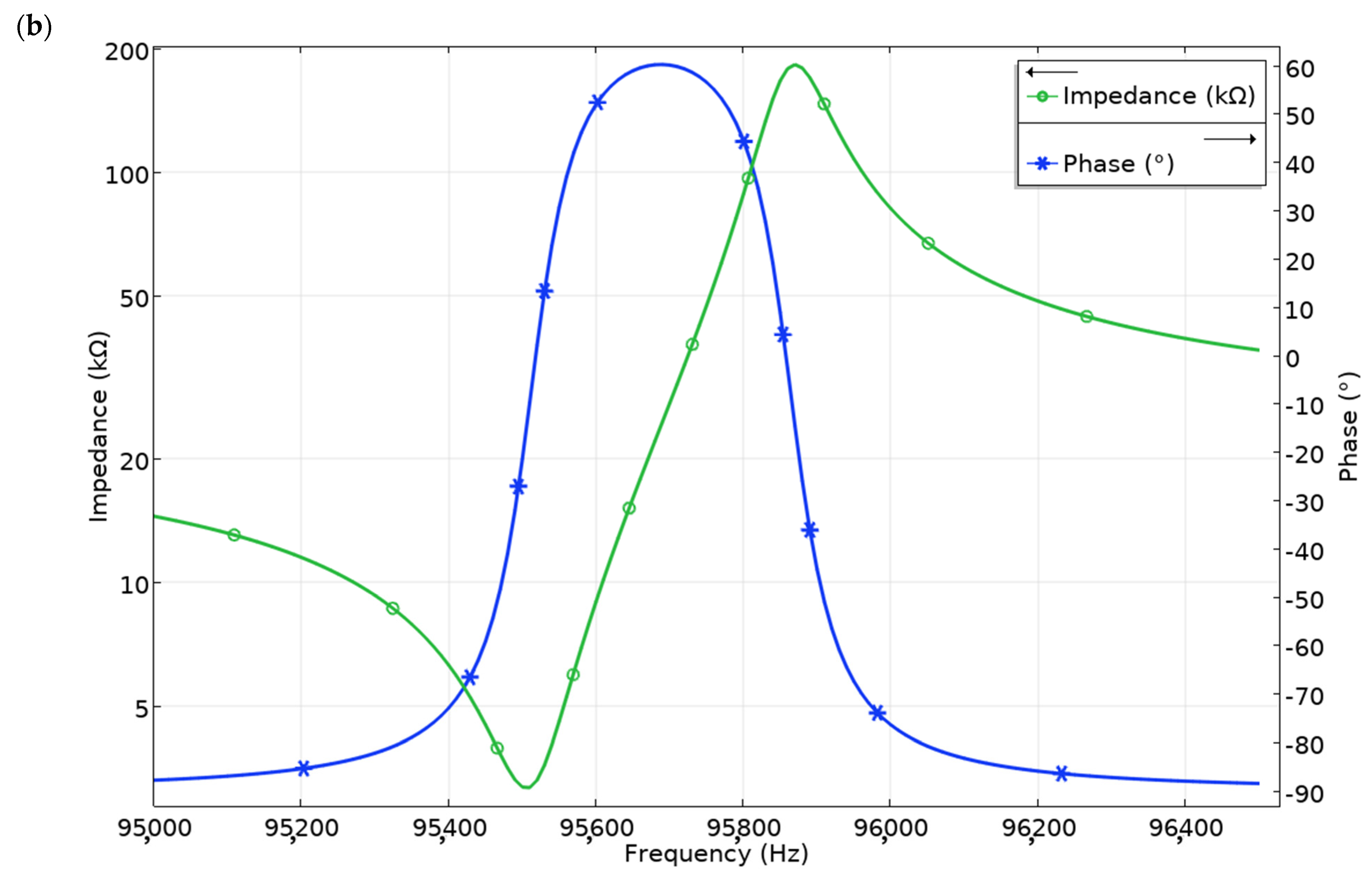
Impedance and phase-frequency characteristics of the robot were analyzed in the frequency ranges of 13.78–13.88 kHz and 95.0–96.5 kHz. Numerical simulation was made when R
0deg and L
0deg segments were excited by the voltage of 50 V
p-p, separately, while the remaining segments of the piezo ceramic ring were set to open-circuit condition. The results of the calculations are shown in
Figure 5.
It can be seen that the resonant frequency of the first bending mode and third radial mode of trapezoidal cantilevers was obtained at a frequency of 13.18 kHz and 95.51 kHz, respectively. There is a minor difference of 1% and 1.5% between modal and resonant frequencies that occurs because of the different electrical boundary conditions used in the model. Moreover, the effective coupling factor keff of the robot is 0.061 and 0.086 when it operates at the frequency of 13.818 kHz and 95.51 kHz, respectively.
The next step of the numerical investigation was performed to analyze the displacement amplitudes of the contact points and coupling ratio between vibrations of different segments of the robot when L and R segments of the piezo ceramic ring were excited. The vibrations coupling ratio is a parameter that shows the ratio between displacement amplitudes of active and passive segments of the piezoceramic ring. It allows evaluating how voltage applied on the active segment of the ring affect vibrations of the contacts used to generate planar and angular motion.
Firstly, simulations were performed when the L
0deg segment used to generate the planar motion of the robot was affected by a harmonic voltage of 50 V
p-p. The remaining segments of the piezoceramic ring were set to open-circuit condition. Analyzing the results of the simulation, it can be noticed that the resonant frequency of the first bending mode of the trapezoidal cantilever is obtained at the frequency of 13.83 kHz (
Figure 6). Displacement amplitude of the contact located on the particular trapezoidal beam and excited by L
0deg segment reached 12.25 μm or 245 nm/V
p-p. It must be noted that vibration amplitudes of contact located on other cantilevers are significantly smaller and do not exceed 3.8 μm. The coupling ratio between contact vibrations located on the active and passive cantilevers is 3.22. On the other hand, the contacts placed in segments R
0deg–R
240deg vibrate as well when the L
0deg segment is exciting. Displacement amplitudes of these contacts do not exceed 0.52 μm and the coupling ratio average is 23.56.
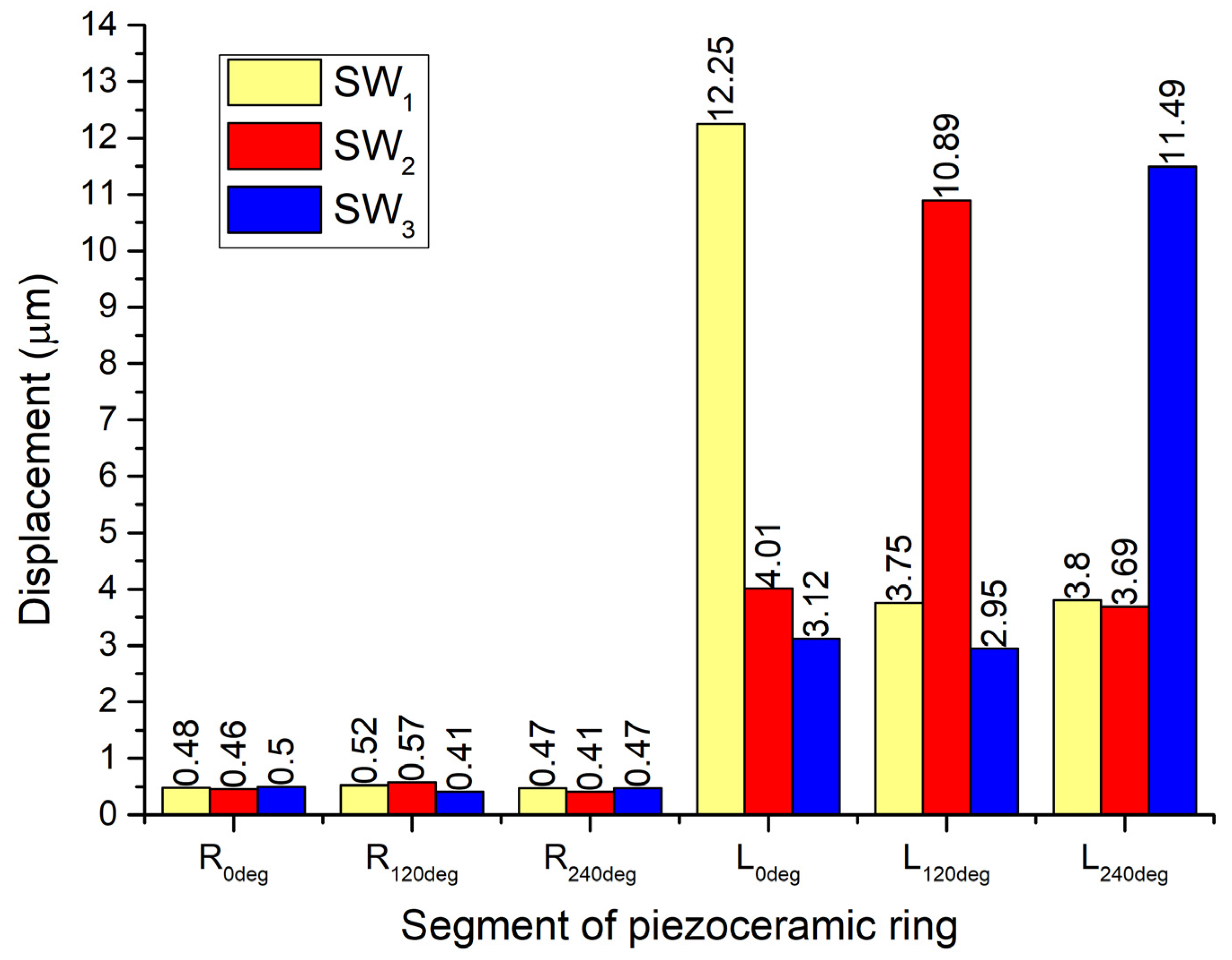
Coupling ratios of the contact vibrations were analyzed in more detail when excitation of L
120deg and L
240deg segments was performed, as is shown in
Table 1. The comparison of the obtained vibration amplitudes is given in
Figure 7. It can be seen that displacement amplitudes of active trapezoidal cantilevers change in the range of 10.89–12.25 μm. The average difference between values is 11.1%. On the other hand, displacement amplitudes of passive cantilevers vary from 4.01 μm to 2.95 μm. The average difference of values is 26.4%. It can be concluded that displacement amplitudes of active cantilevers have smaller displacement differences compared to passive ones. In addition, it can be seen that passive cantilevers have notably lower amplitudes compared to active cantilevers.
Figure 7 shows that contacts located in the segments R
0deg–R
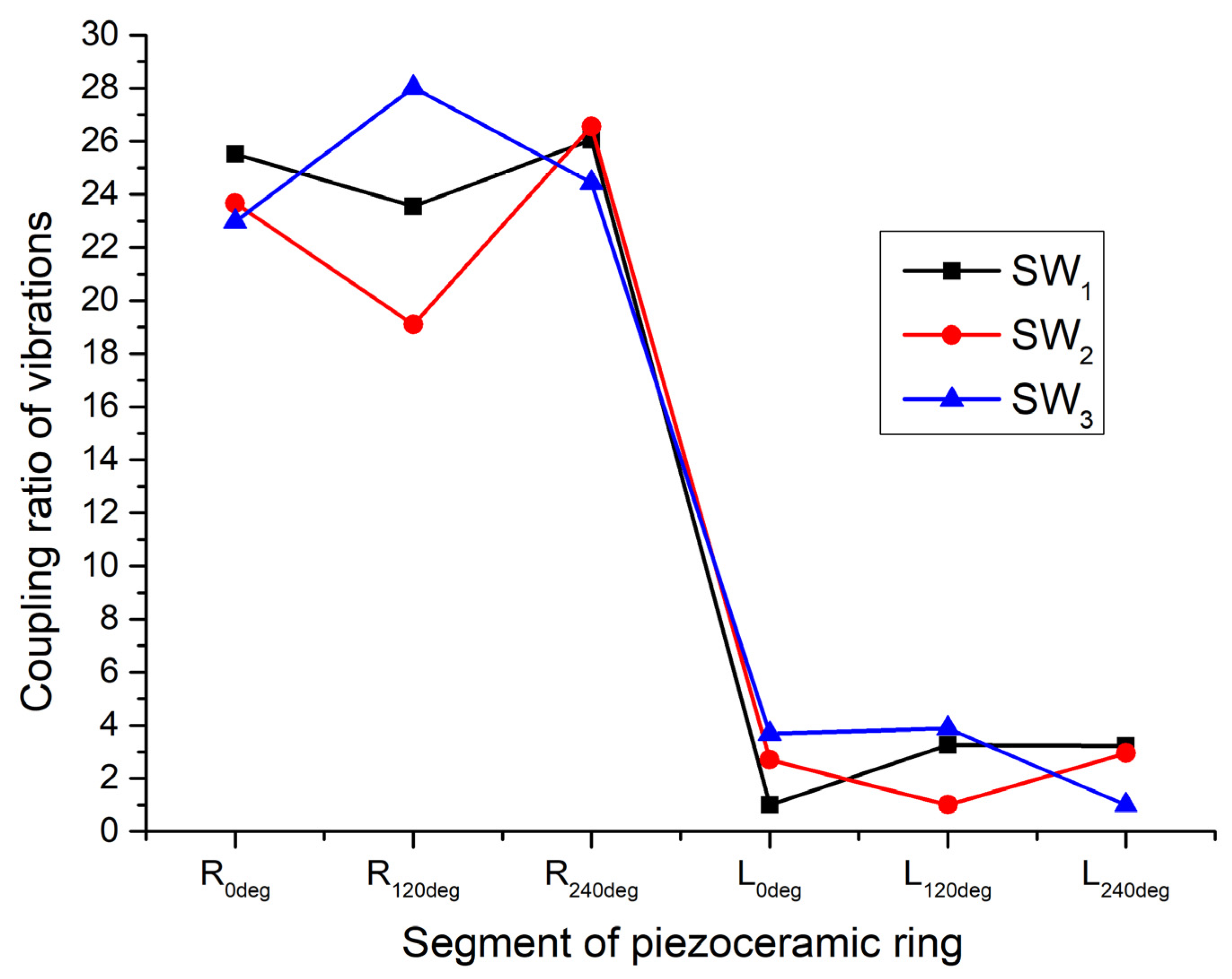
240deg vibrate during excitation of cantilevers; however, the amplitude of vibrations is significantly smaller. The displacement amplitudes vary from 0.57 μm to 0.41 μm. Considering the large difference between displacement amplitudes, it can be assumed that the influence of these vibrations will have a minor influence on the angular rotation of the payload. A comparison of vibrations coupling ratio between different segments of piezoceramic ring is shown in
Figure 8. It can be seen that the coupling ratio of vibrations between L
0deg–L
240 segments of the piezo ceramic ring varies from 2.71 to 3.89 times, while between L
0deg–L
240 and R
0deg–R
240deg it varies from 19.1 to 28.02 times. These results confirm the assumption that during the generation of planar motion, the vibration of trapezoidal cantilevers will have a minor influence on the angular position of the payload.
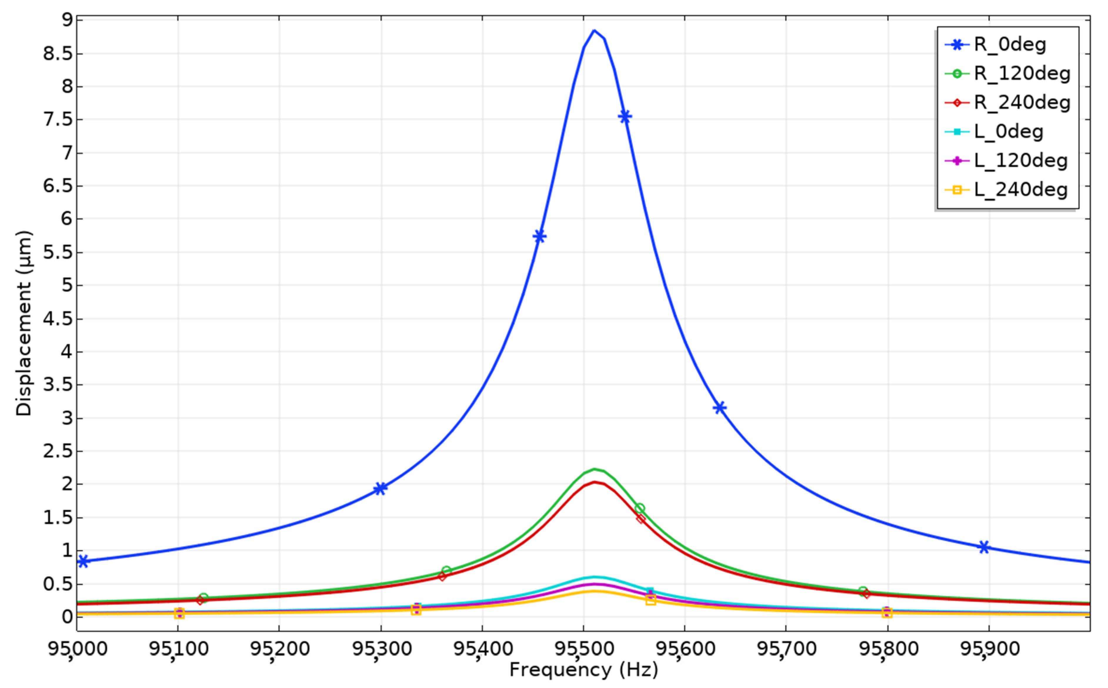
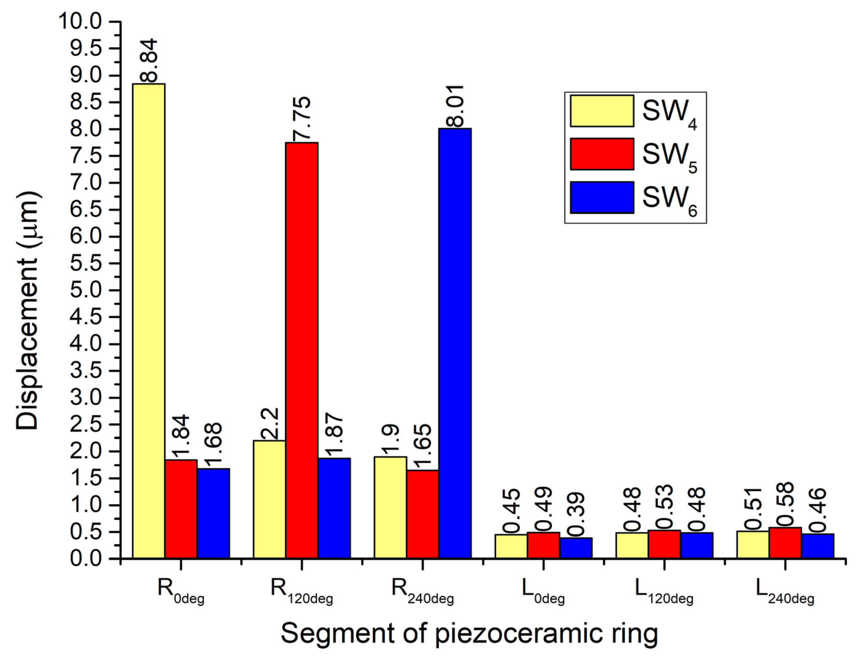
The next step of the numerical study was dedicated to the analysis of displacement amplitudes when segments R
0deg–R
240deg were excited by a harmonic signal at a frequency of the radial mode of the ring and amplitude of 50 V
p-p. Firstly, the calculation was made when voltage was applied to segment R
0deg while other segments were set to open-circuit condition. The results of the calculation are given in
Figure 9.
Peaks of displacement amplitudes occur at the frequency of 95.51 kHz. This confirms the results of modal analysis and impedance–frequency characteristics. The minor difference in resonant frequencies was obtained due to different electrical boundary conditions. The displacement amplitude generated by segment R0deg has a value of 8.84 μm or 176.8 nm/Vp-p, while displacement amplitudes of passive segments R120deg and R240deg reached 2.2 μm. The average vibrations coupling ratio between these segments is 4.01. It must be noted that segments L0deg–L240deg vibrate as well; however, the amplitudes of vibrations are much smaller.
The displacement amplitudes of these segments are up to 0.58 μm when segment R
0deg is affected by an excitation signal. The average coupling ratio of vibrations between L
0deg–L
240deg and R
0deg is 15.24. The same calculations of displacement amplitudes and coupling ratios of vibrations while segments R
120deg and R
240deg are affected by excitation signals were performed (
Figure 10). It can be seen that displacement amplitudes of R
0deg–R
240deg segments vary from 8.84 μm to 7.75 μm. Fluctuations of displacement amplitudes between active segments do not exceed 12.33%. This shows that angular motion characteristics will have similar characteristics in different motion directions.
On the other hand, displacement amplitudes of L
0deg–L
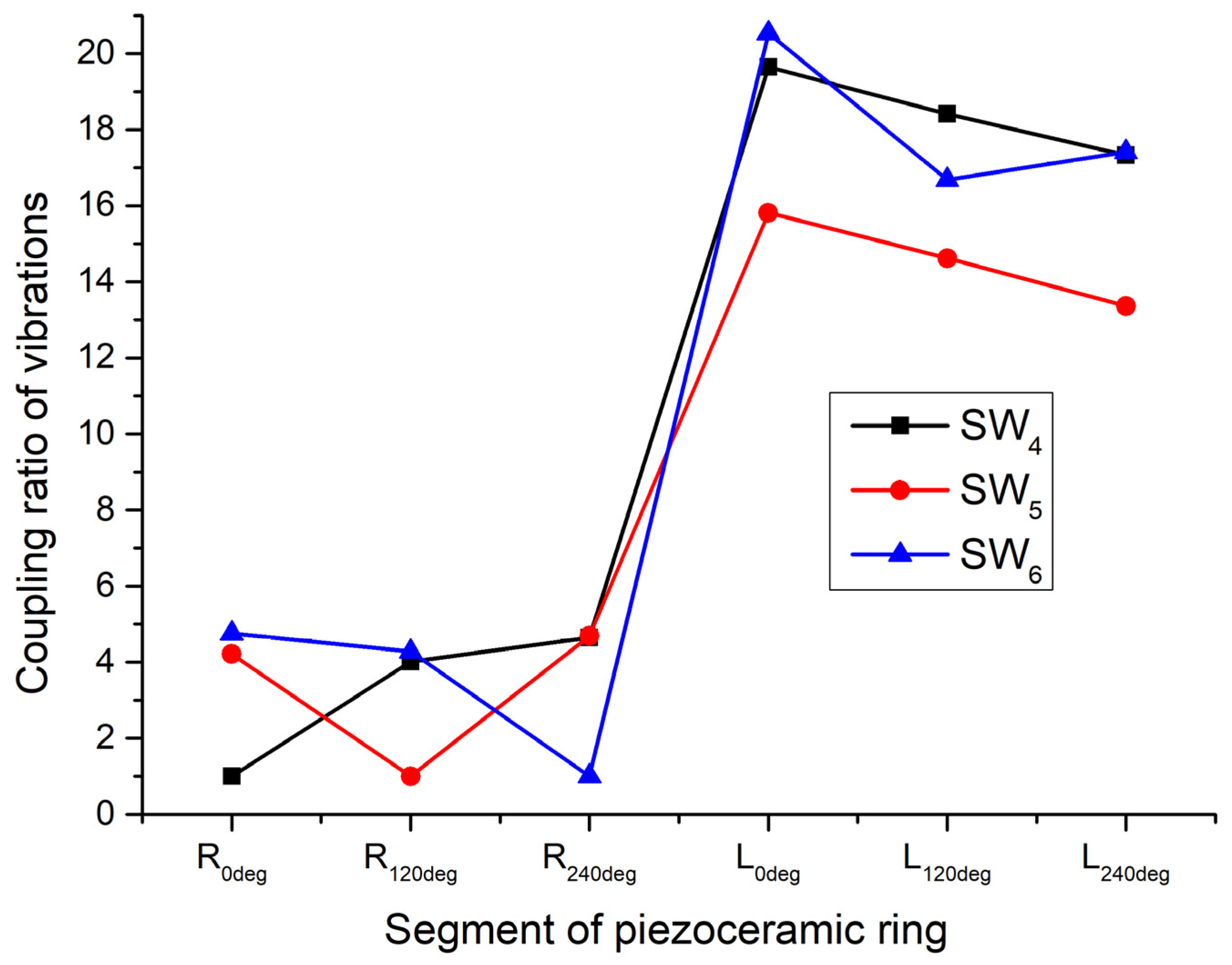
240deg segments differ from 0.58 μm to 0.39 μm. The difference of displacement amplitudes does not exceed 32.76%. Considering low displacement values at these segments, it can be assumed that the angular motion of the payload will have a minor effect on the planar position of the whole robot. Coupling ratios of vibrations were calculated in order to fully represent the results of calculations (
Figure 11). It can be noted that the coupling ratio between vibrations of R
0deg–R
240deg segments varies in the range from 4.76 to 4.01. This shows that the excitation of L
0deg–L
240deg segments has a minor influence on the angular rotation of the payload. On the other hand, the coupling ratio between vibrations of R
0deg–R
240deg and L
0deg–L
240deg segments is in the range from 20.53 to 13.36 times. Therefore, it can be assumed that the generation of angular motion will have a minor influence on the planar position of the robot. On the other hand, high fluctuation of ratio values up to 7.17 times shows that vibrations between L
0deg–L
240deg segments are uneven and should be considered in the design of the robot control algorithm.
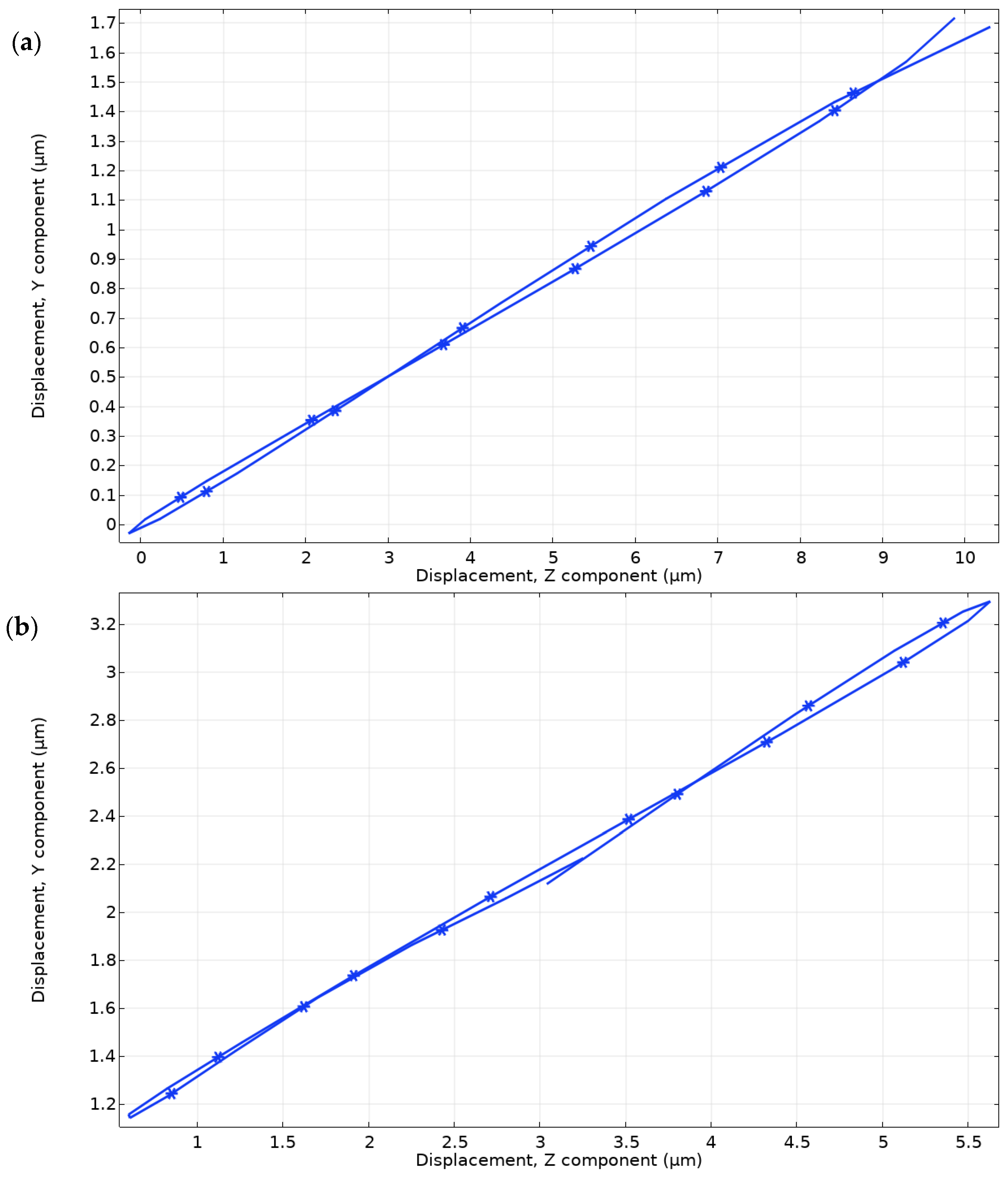
Motion trajectories of the contact points were investigated as well. Two time-domain studies were set up while segments R
0deg and L
0deg were excited by a harmonic signal with an amplitude of 50 V
p-p, independently while remaining segments were set to open-circuit conditions. The range of calculations was set to one period of vibrations of the first bending and radial modes.
Figure 12a shows the displacement trajectory of the contact point located at the end of the trapezoidal cantilever driven by segment L
0deg. The length of motion trajectory projection on the
X-axis is 9.8 μm, while on the
Y-axis it is 1.78 μm. The trajectory of motion is almost a line and has an inclination. Therefore, it confirms the assumption that the robot will generate planar motion under the vibroimpact principle.
Figure 12b shows the displacement trajectory of the contact point located on top of segment R
0deg. Length of motion trajectory projection to
X-axis is 5.56 μm while to
Y-axis 2.01 μm. As in the case before, trajectory shape is almost a line and has an inclination. This confirms the assumption that angular motion of payload can be generated under vibroimpact operation principle as well.
Numerical investigation showed that the proposed design of the robot can provide planar and angular motions independently. However, the vibrations coupling between different segments exists when any segment of the piezoceramic ring is excited by an electric signal. On the other hand, the values of the coupling ratio show that vibrations coupling have a minor influence on the accuracy and direction of angular and planar motions and can be controlled.
4. Experimental Investigation of the Robot
The prototype of the robot was made to perform experimental investigations. The geometrical and physical characteristics of the robot were set in accordance with the numerical model (
Figure 13). The goal of the investigation was to validate the operation of the robot and measure the electrical and dynamic characteristics.
Impedance–frequency characteristics were measured to find resonant frequencies of the robot. Impedance analyzer SinPhase 16777k (SinPhase, Mödling, Austria) was used. The robot was placed on a soft surface and measurements were made without payload. Firstly, the impedance analyzer was connected to the L
0deg segment, while other segments were set to open-circuit condition. The same measurements proceeded using segment R
0deg. The results are shown in
Figure 14. Resonance frequencies of the first bending mode of the trapezoidal cantilever and the third radial mode of the piezo ceramic ring were obtained at the frequencies of 14.55 kHz and 93.15 kHz, respectively. The differences between calculated and measured resonance frequencies are 1.44 kHz or 5.1% for the first bending mode and 2.36 kHz or 2.47% for the radial mode. Mismatch of the resonant frequencies comes because of the calculation errors, differences in boundary conditions during calculations and measurements, and slight differences in material characteristics. On the other hand, differences do not exceed 5%. Effective coupling factor
keff was calculated for both modes. The first bending mode of the trapezoidal cantilever has
keff = 0.056, while for the radial mode
keff = 0.071. Compared to the calculated values, the difference does not exceed 8.2%.
The next step of the experimental investigation was to measure the planar and angular speed of the robot.
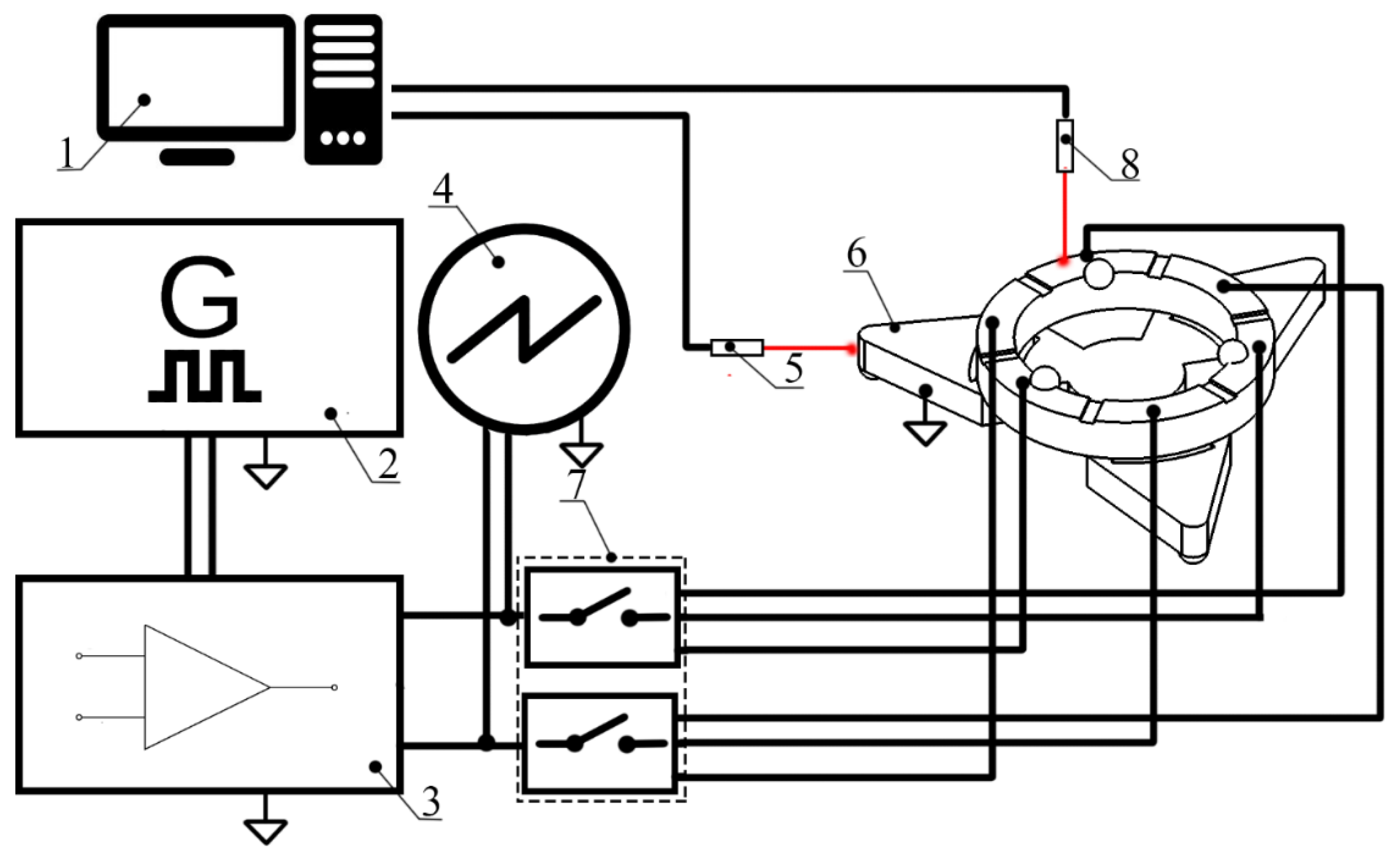
Supplementary Materials Videos S1 and S2 represents robot operation. The experimental setup was built for this purpose (
Figure 15). The experimental setup included a computer, a function generator WW5064 (Tabor Electronics, Nesher, Israel), a power amplifier PD200X4 (Piezo Drive, Shortland, Australia), oscilloscope DL2000 (Yokogawa, Tokyo, Japan), a displacement sensor ILD 2300 (Micro-Epsilon, Ortenburg, Germany), tachometer DT210 (Nidec-Shimpo, Tokyo, Japan) and self-made switch boxes.
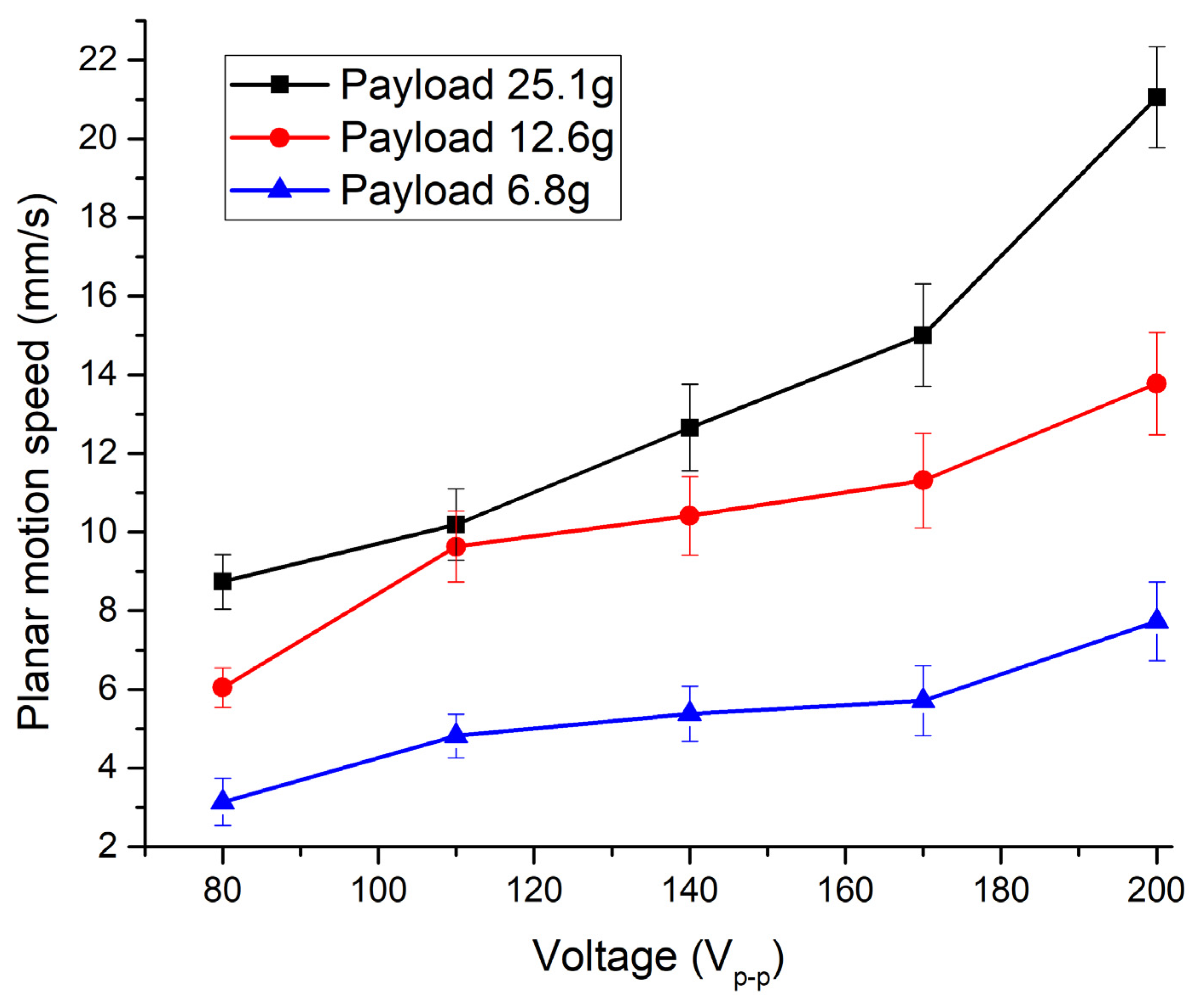
Planar motion characteristics were measured when segment L
0deg was affected by an excitation signal in the range from 80 V
p-p to 200 V
p-p with an increment of 20 V
p-p. Segments R
0deg–R
240deg and L
120deg, L
240deg were set to open-circuit condition for this investigation. In addition, the investigation was made when different payloads were applied to the robot, i.e., 6.8 g, 12.6 g, and 25.1 g. Experiments were made by placing the robot on glass. The results of the investigation are given in
Figure 16. It can be seen that the lowest planar motion speed was obtained while excitation signal amplitude and payload were 80 V
p-p and 6.8 g, respectively. It reached 3.13 mm/s or 39.12 μm/s/V
p-p.
It can be seen that the weight of the payload affects the motion speed of the rotor. When the payload is increased up to 12.6 g, the speed reaches up to 6.01 mm/s or 75.12 μm/s/Vp-p. When the mass of the payload is 25.1 g, the planar speed increases up to 8.73 mm/s or 109.1 μm/s/Vp-p. This shows that planar speed increases when payload increases as well.
The highest planar motion speed of 21.1 mm/s or 105.5 μm/s/V
p-p was obtained when a payload of 25.1 g was used and voltage of 200 V
p-p was applied. The speed reached the value of 13.77 mm/s or 68.85 μm/s/V
p-p and 7.72 mm/s or 38.6 μm/s/V
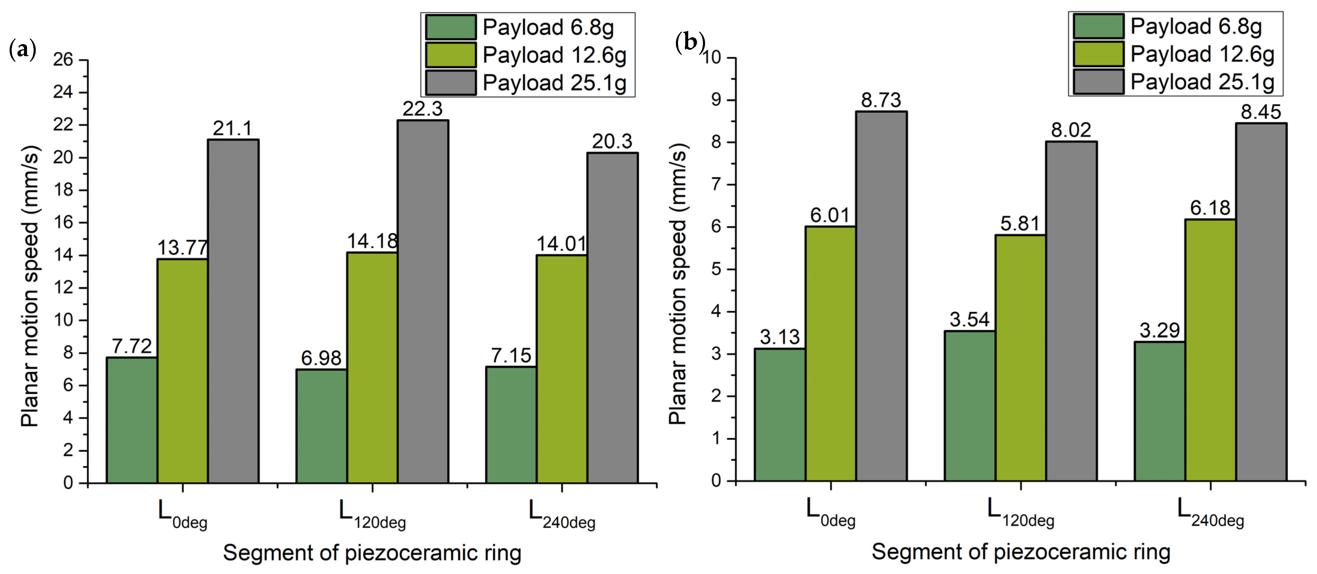
p-p when payloads of 12.6 g and 6.8 g were used at the same voltage, respectively. Measurements showed that planar speed almost linearly depends on voltage. Therefore, in order to fully investigate planar motion characteristics of the robot, the same experimental studies were performed while segments L
120deg and L
240deg were driven by excitation signal. A summary of the measurement results is shown in
Figure 17.
The highest planar speeds generated by different piezoceramic segments have different values that depend on the payload applied to the robot. Fluctuations of speeds values, while payloads of 6.8 g, 12.6 g, and 25.1 g are applied, are around 9.58%, 2.82%, and 8.96%, respectively. Therefore, it can be found that the lowest planar speed fluctuations are obtained while a payload of 12.6 g is used. It can be assumed that a payload of 12.6 g will ensure the most even planar motion speed in different directions. On the other hand, the lowest planar speeds have significantly lower values when different payloads are applied. The difference is more than 50% compared to the highest ones. However, the difference between the lowest values also depends on payload, with values of 11.58%, 5.37%, and 8.13% while 6.8 g, 12.6 g, and 25.1 g payloads are applied, respectively. Therefore, it can be found that the most suitable payload is 12.6 g. On the other hand, planar motion speed achieved at this payload is lower by 36.41% compared to planar speed obtained while 25.1 g payload was applied.
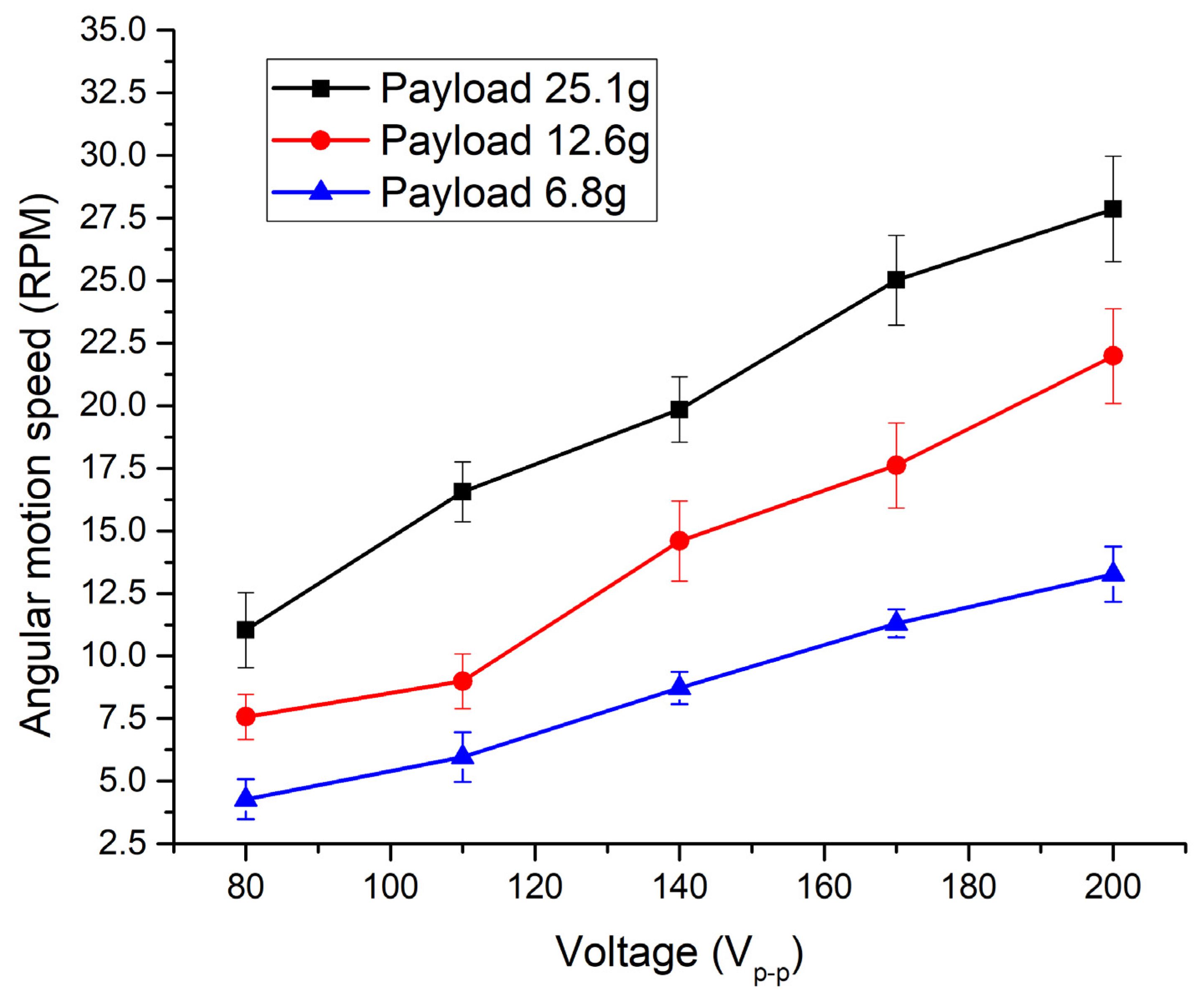
Experimental investigation of angular speeds was performed as well when segments R
0deg–R
240deg were excited by harmonic voltage. The same experimental setup was used (
Figure 15). Firstly, the angular motion speed of the payload was investigated when the R
0deg segment of the piezoceramic ring was excited while segments R
120deg, R
240deg, and L
0deg–L
240deg were set to open-circuit condition. Excitation voltage changed in the range from 80 V
p-p to 200 V
p-p. The measurements were made using three different payloads. Results are given in
Figure 18.
The lowest angular motion speed was obtained when the R
0deg segment was affected by an excitation voltage of 80 V
p-p and payload of 6.8 g. The angular speed reached 4.27 RPM or 0.053 RPM/V
p-p. On the other hand, while payload values and excitation signal amplitude were 12.6 g, 25.1 g, and 80 V
p-p, the angular speed of the payload reached 7.56 RPM or 0.0945 RPM/V
p-p and 11.03 RPM or 0.137 RPM/V
p-p, respectively. It can be seen that angular motion characteristics at the lowest excitation signal amplitude have stable and almost linear characteristics. The highest angular motion speed was obtained while excitation voltage was set to 200 V
p-p and payload was 25.1 g. At these conditions, angular motion speed reached 27.85 RPM or 0.348 RPM/V
p-p. At the same excitation signal amplitude and payloads of 6.8 g and 12.6 g, angular motion speed reached 13.26 RPM or 0.066 RPM/V
p-p and 21.98 RPM or 0.109 RPM/V
p-p, respectively. It can be seen that angular motion speed has almost linear dependence from voltage when segment R
0deg is excited. Experimental studies were performed when segments R
120deg and R
240deg were excited as well. A comparison of the lowest and highest angular motion speeds is given in
Figure 19. It can be seen that the highest angular motion speed was obtained when the payload of 25.1 g was applied. Angular motion speeds at this payload have a difference of 4.94%. On the other hand, at payloads of 6.8 g and 12.6 g, differences of angular speeds in different directions are 12.89% and 4.29%, respectively. Therefore, the lowest difference of angular speed values was obtained when the payload of 12.6 g was used.
Analysis of the results presented in
Figure 19b shows that the lowest angular motion characteristics were achieved while the payload of 6.8 g was used. Differences in angular motion values in different directions do not exceed 12.67%. Differences in angular motion speeds do not exceed 11.37% and 13.82%, respectively when the payload of 12.6 g and 25.1 g were used. The lowest differences of angular motion speeds were obtained when a payload of 12.6 g was used. Based on the obtained results, it can be concluded that it is the most suitable payload value for the robot.


