1. Introduction
Over the last decades, the legislated maximum levels of emissions from engines have been tightened more and more. Worldwide, in 2014, transport as a whole was responsible for 23% of total CO
2 emissions from fuel combustion and road transport was responsible for 20% [
1]. The vast majority of heavy-duty vehicles (HDVs) in Europe are powered by diesel engines and, although they account only for 4% of the vehicle fleet, they have been identified as important sources of both pollutant and greenhouse gas (GHG) emissions. Exhaust gases from diesel engines include carbon monoxide(CO), particulate matter (PMx), nitrogen oxides (NOx) and sulfur oxides (SOx) [
2]. NOx contributes to serious environmental problems, such as acid rain and photochemical smog [
3] and human health problems, especially respiratory disorders [
4,
5].
With the aim of reducing this contribution, the EU has adopted the strategy of supporting a mix of technologies, currently at high levels of maturity, depending on the transport modes and the travel range. The main response of the industry to the introduction of more stringent emission standards was the widespread use of selective catalytic reduction (SCR) technology for reducing NOx emissions at the tailpipe combined with diesel particle filters (DPF) for PM reduction and diesel oxidation catalysts (DOC) for the oxidation of incomplete combustion products [
6]. The urea-based selective catalytic reduction (urea-SCR) technology, a lean NOx after-treatment technology, has been widely used owing to its impressive NOx reduction efficiency and compliance with newly rigorous specifications [
7,
8]. In the SCR technique, a urea-water solution (UWS, 32.5% aqueous solution) is injected into hot exhaust gas using different strategies according to the manufacturer of the vehicle. After evaporation of water from UWS, the urea decomposes and gives out ammonia which is the reducing agent for the reduction of NOx. Reduction of NOx takes place when ammonia reacts with NOx over catalyst through different catalytic reactions.
However, exhaust temperature plays an important role in catalyst performance. It tends to be rather low in real driving cycles, which causes low catalyst efficiency [
9]. In [
10,
11,
12] authors registered the exhaust temperatures during NEDCs and WLTPs from cold and hot conditions. During the cold NEDC, the inlet temperature was below 130 °C in the majority of the first 400 s, and temperatures greater than 180 °C were achieved only in a small portion of the hot driving cycle. This behavior strongly affects the conversion efficiency of SCR devices because a minimum substrate temperature of 180 °C is required to reach the SCR light-off. As a result, higher activity of SCR catalysts at low temperatures is mandated to effectively reduce real-world NOx emission while fuel economy requirement must be simultaneously met. A lot of effort has also been made, but the main obstacle is that during low-speed urban driving and cold-starts, HDV’s engines only generate exhaust gas temperatures below 200 °C, which is not enough for the conventional urea-SCR based systems to reach the SCR light-off [
13].
This issue is of great concern in combustion vehicles and several strategies for solving it are currently under development. These can be divided into: (1) engine control and (2) catalyst control. Engine control strategies are focused on increasing the exhaust gas temperatures as fast as possible. Several ways are currently under study, such us retarding the ignition timing, increasing the idling speed, bypassing the turbocharger for creating a fuel rich mixture, alternating rich and fuel lean conditions, injecting more fuel at starting conditions in dual fuel vehicles, etc. [
9,
14,
15,
16,
17].
However, all these engine control techniques tend to strongly increase the fuel consumption and, therefore, reduce the net vehicle efficiency. Gao et al. reflected on the need to develop integrated and more advanced thermal management control strategies to reduce light-off time without significant energy penalty [
18]. On the other hand, the catalyst control technologies are simpler and do not require modifying the engine’s set up since they are focused on reducing the light-off temperature of the catalytic conversion by means of trying to develop alternative catalytic materials and/or reducing the time to reach the light-off temperature. This second and more realistic strategy is currently investigating several alternatives such as increasing the heat transfer inside the catalyst using higher cell densities and thinner wall designs, insulating the exhaust manifold, and moving the SCR as close as possible to the engine’s block or adding an electrical resistance to preheat the SCR. All in all, the simplicity of electrically preheated catalysts (EHCs) makes it the most cost-effective technology for solving the problem [
9,
18].
In this direction, several prototypes of a catalytic converter with an exhaust heater for preheating the catalyst specifically designed for CNG engines have been tested with very promising results [
18,
19]. These heat-integrated catalysts require a constant heating of 2.5 kW during 120 s in a 1.8 L CNG engine for a 90% reduction of CH4 emissions in a New European Driving Cycle (NEDC) test in comparison with non-preheated TWC values. NEDC consists of repeated urban and extra-urban driving cycles usually performed on a roller test bench with a total duration of 1180 s. This 2.5 kW in 120 s is equivalent to a mean electrical power consumption of 254 W during the NEDC that must be generated by the alternator and, hence, by the engine. This is the reason why this technical solution contributes to increasing the fuel consumption of the vehicle.
Massaguer et al. [
20] analyzed the use of an automotive thermoelectric generator (ATEG) coupled to an exhaust gas heater (EGH). This system could reduce up to 97% the NOx emitted by a light duty vehicle during cold starts. The ATEG is used to convert waste heat from exhaust gases, downstream of the aftertreatment system, into electricity. A battery is used to store the electricity generated, which can be used by the EGH later to shorten the time that urea is injected and reduce NOx emissions. This EGH + ATEG system, also known as thermoelectric aftertreatment heater (TATH), was designed to be energetically autonomous, so there is no extra consumption of fuel. Note that the ATEG generates less power than the EGH. However, the EGH only works for a few minutes while the ATEG all the driving cycle. Therefore, the energy consumed and produced can be balanced.
This study is based on the developments presented in [
20,
21] but from a perspective of compliance with current EURO VI and future EURO VII regulations. The objective of this work is to experimentally quantify the energy required by an EGH to fulfil the EURO VI and EURO VII regulations. The EGH will be retrofitted upstream of the standard after-treatment system of a EURO VI certified HDV. The idea is to obtain the power and energy needed to make SCR work at its maximum efficiency. Then, the effect of the added weight, the additional back pressure caused in the exhaust pipe and the extra electricity consumption will be analyzed. This will lay the groundwork for the future development of a thermoelectric recovery system capable to produce the energy required by the EGH in a real mission of a long-haul Euro VI HDV. The end goal is reducing the pollutant emissions without the need to increase the fuel consumption.
2. Proposed System
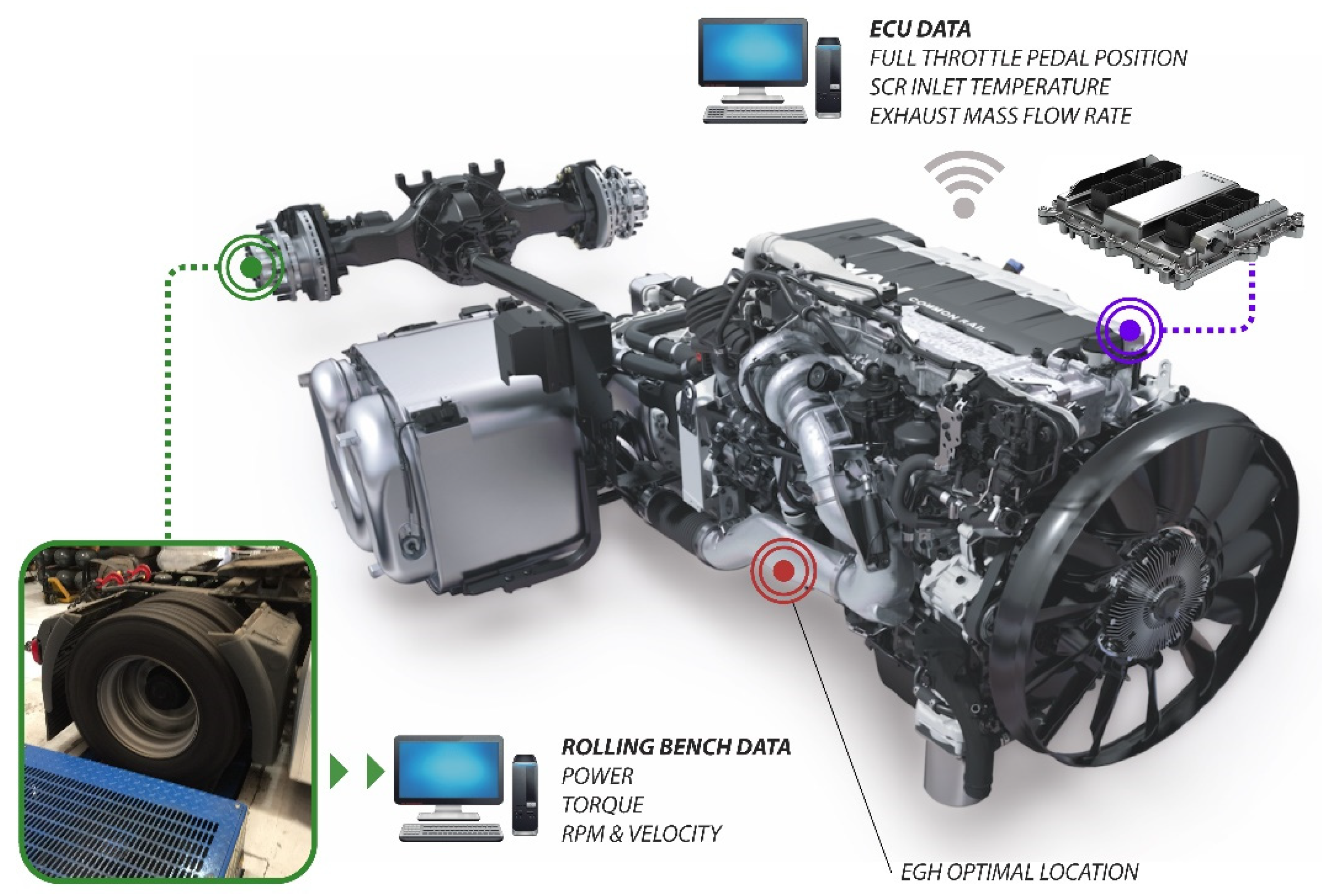
In order to stablish the basement for this study, it was necessary to choose the optimal combination of elements that suited our requirements. In first place, it was clear that strict values of NOx emission form standard Euro VI would be a good starting point. This pollution limitation is a great challenge for all sorts of transport vehicles, especially for heavy duty vehicles manufacturers. Man Truck & Bus A.G. (Munich, Germany) is an example of how the use of sophisticated ECU software, combined with catalytic chemical reactions, can obtain NOx ppm values below Euro VI limits. The vehicle used in this article is a Euro VI certified HDV from MAN, model TGX 18.480 Efficient Line 2. The vehicle disposition and the main data acquired can be shown in
Figure 1.
The system proposed is based on the existing aftertreatment system (ATS) retrofitted by an EGH. The EGH, shown in
Figure 2, was located upstream of the ATS and, in essence, it is a 12 kW electric coil temperature controlled by a PID system. To simplify the test, the EGH was not powered by the vehicle’s battery, but it was connected directly to the electrical network. The control unit adjusted the power injected to the EGH according to the temperature set point. Apart from the data acquisition shown in
Figure 1, it is also necessary to gather other important parameters such as EGH inlet and outlet temperatures,
and
respectively and the electrical power consumption of the EGH
. The EGH coupled to the standard exhaust system can be seen in
Figure 3.
As seen in
Figure 3, EGH (number 1) has been located downwards the turbochargers, just before the standard ATS. The next element we find is the diesel exhaust fluid (DEF) unit composed by a tank, a supply module, and a dosing module (number 2). The vehicle tested in this experiment uses AdBlue for NOx abatement. The ECU is the responsible of the AdBlue parameters, which is never injected into the system until the exhaust gas temperature exceeds 180 °C. Inlet gas temperature and NOx content are read by the dosing unit to adjust the exact dose of AdBlue required to meet the EURO VI standard.
Next component we find is a closed unit composed by a selective catalytic converter (SCR) and a continuous regenerating trap (CRT). At this point a mix of AdBlue and exhaust gases enter into the SCR (number 3). Inside this device a catalytic reaction is produced to convert NOx into diatomic nitrogen (N2), and water (H2O). Carbon dioxide (CO2) is a subproduct of this reduction when urea is used as DEF. Finally, it is necessary to eliminate NH3 produced by the reaction between AdBlue and NOx. Using an ammonia catalyst, included into SCR system, NH3 is converted into nitrogen and water.
Afterwards the SCR and within the same package the CRT (number 4) is divided into a diesel oxidation catalyst (DOC) and a diesel particle filter (DPF). The DOC is the responsible of CO and THC oxidation while the DPF is used to capture the unburned particles. Soot trapped in the DPF walls is burned when an excessive backpressure is reached. The same closed unit is the standard exhaust outlet where NOx sensor is coupled to acquire the vehicle emissions .
Regarding
Figure 3, there is a representation of an ATEG (number 5) to demonstrate which is going to be its suitable location, just at the end of the standard ATS. Its outlet manifold would be the collector of exhaust fumes where the NOx sensor is attached in this figure. This ATEG is a conceptual approach of size, location and design. The tested vehicle has its NOx sensor connected at the exhaust outlet, underneath the SCR + CRT unit.
3. Materials and Methods
To evaluate the influence of the EGH in NOx emissions reduction, a certified bench for Heavy Duty vehicles was used. The experiment series were held in EVARM S.L. facilities which had a certified test bench for testing HDVs (Powerdyno R200/1, Maha, Bescanó, Spain) was used to put the vehicle in real operating conditions. This equipment was also used to capture the FTPP, NOx after and before the ATS, and exhaust temperatures from the ECU. The measurement of NOx emissions was done with a MIAC G4.0 located at the end of the exhaust pipe. This device presents a measure range from 0 to +5000 ppm, an accuracy of ±5% of mv (+100 to +2000 ppm) and ±5 ppm (0 to +99.9 ppm) with a resolution of 0.1 ppm (0 to +500 ppm). A Power Explorer PX5 power meter (Dranetz, Nürnberg, Germany) was used to measure the EGH power consumption with the following specifications: voltage measuring range from 1–600 Vrms with 0.1% rdg (reading) + 0.05% FS (full scale), 256 samples/cycle, 16 bit ADC; current measuring range from 1–6000 Arms with 0.1% rdg + CTs (4), 256 samples/cycle, 16 bit ADC. Exhaust temperatures were recorded with a National Instruments DAQ with one NI 9211 acquisition module. This device presents a maximum measure error of 2.2 °C (0–400 °C) with a measurement sensitivity < 0.07 °C. All temperature probes used were type K thermocouples.
The method used to calculate absolute uncertainty values depends on the equipment accuracy. These parameters are obtained from datasheet provided by different manufacturers as exposed before. Thus, temperature and NOx measurement standard uncertainties have been calculated. Voltage and current (used to calculate EGH power consumption) are separately obtained and its uncertainties also calculated using the same method. As EGH power is an indirect parameter, its uncertainty is the result of both electrical magnitudes as it depends on these parameters [
22].
In this study, a Heavy-Duty Vehicle Euro VI TGX 18.480 Efficient Line 2 from MAN was used to carry out the tests. Its specifications are summarized in
Table 1.
Figure 4 shows the rolling bench with the vehicle tested. All tests were carried out using the same load.
Three different engine regimes were selected to conduct the study: 1000 rpm (≈
), 1250 rpm (≈
) and 1500 rpm (≈
). All these regimes, shown in
Figure 5, can be found in a typical daily drive. The suitable gear to obtain all range of full throttle pedal position (FTPP) values was the eleventh. During all tests, the engine temperature stayed below 90 °C to keep the same engine conditions. Before each test, the vehicle was warmed up at idle for 20 min. NOx emissions were captured along the tests. Maximum FTPP tested is 90% to assure that can be reached equally in all conditions. In all tests, the setpoint temperature of the EGH was set to 300 °C to ensure that the exhaust gas temperature at SCR inlet was above the SCR light-off temperature of 220 °C.
4. Results
Figure 6 shows the NOx emissions and the EGH performance during the 1000 rpm test. The first thing that must be mentioned is the fact that the standard aftertreatment system (without the EGH) is not capable to fulfil the EURO VI regulation. EURO VI NOx limit has been calculated from the WHTC limit value multiplied by the conformity factor CF:
. As can be seen in
Figure 6, NOx emissions are higher than the limit >
.
The new Euro 7/VII, which will be presented at the end of 2021 and expected to come into force on 2025 [
23], will develop stricter CO
2 and NOx limits, as well as new tests and limits for non-CO
2 greenhouse gas emissions [
24]. There is no decision yet, but some reports point out that NOx limits will be halved from Euro VI, placing the limit around 0.2 g/kWh [
25,
26,
27]. Then, the limit value will be
.
Around 40% of FTTP, temperature presents a great decline and it produces a significant increase of NOx emissions that is well maintained until 65% of FTPP. The vehicle catalytic system needs to achieve temperature much over these values to start its reaction. This explains also the importance of reaching the urea injection target temperature as soon as possible in order to start catalytic conversion at the standard ATS. Without enough temperature (lower than 225 °C in this test) and without urea solution injected, NOx values remain high within medium range FTPP.
However, the inclusion of the EGH had a very positive impact. It can be noticed a significant NOx reduction, specially at medium FTPP range (40–65%). It is remarkable how NOx values without heater descend drastically after temperature exceeds the barrier of 260 °C, onwards 65% of FTPP. This phenomenon can be explained by the injection of AdBlue that drastically increase the SCR efficiency. Ideally, AdBlue injection starts when SCR inlet temperature exceed 220 °C. In this case it can be observed that the injection starts at 260 °C. This difference can be explained by the heat loss in the section from the EGH to the SCR and also by the thermal inertia of the SCR substrate that needs a few seconds to reach the temperature injection threshold. It is important to note that this mismatch is present in all tests. Below 260 °C, in EGH off mode, the trend of is mostly influenced by EGR valve that is controlled by ECU manufacturer parameters.
On the other hand, using the heater, temperatures were always far higher than the AdBlue injection threshold of 220 °C (275 °C minimum) and therefore NOx reduction is improved drastically. Note that during , EGH was disabled and consequently temperatures . This achievement is maximized at medium FTPP values as data registered is below 0.2 g/kWh. This difference is minimized at 90% FTPP as thermal engine produced more heat and temperature values almost coincide in both cases. Consequently, as time passes and FTPP increases, power consumption decreases.
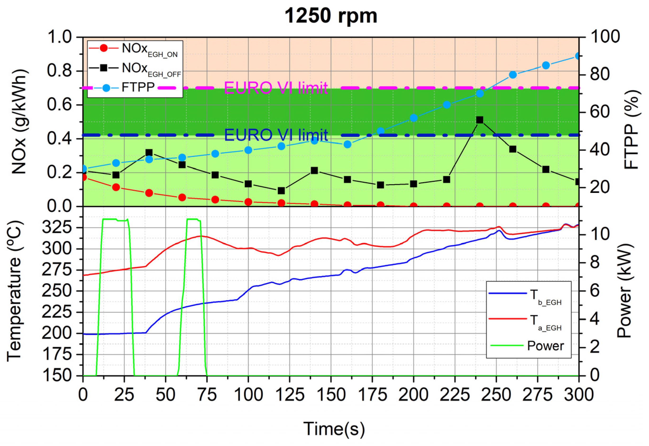
The second cycle was set at 1250 rpm, as shown in
Figure 7. Unlike
Figure 6, in this case the standard aftertreatment system is capable to fulfil the EURO VI regulation. Notice that NOx emission ranges from 0.1 to 0.3 until 65% FTPP. It is a narrow variation explained by the fact that this engine regime produces a greater impact in temperature increment as
numbers show. At the end of the test both temperatures present the same values (after 250 s). The catalytic conversion benefits from these values over 300 °C and NOx emissions provide a rapid decrease despite FTPP values are high.
On the other side, the use of the EGH continues to be beneficial in reducing NOx emissions below EURO VII limit. values decreased as FTPP increased and remained around 0 g/kWh for almost the second half of the test. The main NOx reduction was performed at high FTPP values in contrast to test 1. However, they share the same drastic reduction of values at 70% of FTPP that can be explained due to AdBlue injection. In this case it can be noted that, when EGH was disabled, the AdBlue injection started at 220 °C approximately. When EGH was enabled, the AdBlue injection started at the beginning of the test. Apart from that, it can be observed that a higher produce a higher SCR conversion and a higher NOx reduction. Both and temperatures converge at the end of the test.
Finally,
Figure 8 shows the results at 1500 rpm. Note that at 65% and 70% FTPP NOx emissions are higher than the EURO VI limit. Following the trend of the other cases, at 1500 rpm the EGH maintains its capacity to abate NOx emissions and it can cut NOx emissions below EURO VII limit. During the first FTPPs, both
and
emissions were very low. This phenomenon can be explained by the EGR activation until 50% FTPP that contributed positively to the NOx reduction, despite of the low exhaust gas temperature.
On the other hand, NOx reduction is also remarkable at second half of the test coinciding with lower energy consumption as heater is no longer needed thanks to above target selected in the controller of the EGH. For FTPP values higher than 70%, values are reduced in great numbers. This is due to the AdBlue injection according to the aforementioned injection threshold limit, which was clearly exceeded at 70% of FTPP. In contrast, the gap between 40–70% of FTPP is where were higher. In this case, a moderate engine regime and medium FTPP range (around 50%) NOx emission values of the standard ATS increase rapidly. This phenomenon is a result of a combination between the greatest engine regime at moderate FTPP and relatively low exhaust gas temperature, both counterproductive in order to catch pollutants within the ATS. Consequently, it is in this range where NOx reduction, thanks to the inclusion of the EGH, was higher.
Results presented in
Figure 6,
Figure 7 and
Figure 8 include error bars of data of less than 5% in all cases. Its small size (smaller than graphic symbology) makes it unable to represent it properly.
Summarizing, NOx emissions are reduced in all cases but in different ways and conditions. As seen in
Table 2, we find lowest exhaust temperatures and EGH highest consumption in Test 1. Low engine regimes produce low exhaust temperature. That is the reason why both NOx reduction and EGH consumption were the highest of the three tests. Under these conditions, the heater needed more electrical power to fill the temperature gap and also increased the AdBlue consumption. Once SCR light-off was achieved, the ECU started the AdBlue injection.
5. EGH Optimization
From the results presented above, one can realize that a 12 kW EGH, such as the one tested in this paper, is extremely disproportionate considering that this power should come from an on-board generator (i.e., alternator). Although this huge amount of power provides a great increase in
with initial values over 260 °C, if we consider the manufacturer SCR efficiency curve represented in
Figure 9, it can be observed that heating exhaust gases above 220 °C has no sense. The SCR presents a maximum efficiency point of 95% at
. Temperatures above this value will not bring any improvement in NOx reduction but will cause the alternator to consume more fuel to feed the EGH.
From the experimental data presented in the previous section it has been possible to draw the experimental SCR efficiency curve. From
Figure 9, it can be seen that when the EGH is active the curve maintains the efficiency above 90% for temperatures below 220 °C. Note that the points within the circle cannot be taken into account since urea was not being injected at that moment. This can be explained by the fact that the urea injection decision is made from the temperature of the substrate, and not from the temperature of the gases going into the SCR,
, used in
Figure 9.
With value set at 220 °C, and exhaust mass flow rate known from the previous tests it is possible to determine the theoretical power consumption to achieve 95% of SCR conversion efficiency.
Figure 10 shows the optimized EGH power that guarantees a SCR efficiency of 95%. Note that these values consider that all the electrical energy consumed by the EGH was exchanged as thermal energy into the exhaust gases. It can be observed that its consumption is lower than the EGH power used in previous tests. At 1000 rpm, there is a top consumption peak of 5 kW and it is remarkably lower than the 11 kW achieved during the test 1. Its consumption value is zero only at the end of the test when
is over 220 °C and no extra energy is needed. At 1250 rpm, the theoretical EGH power reach a peak of 2.2 kW during the first 50 s of testing and remains zero after
exceeds the 220 °C target. Finally, in test 3 it can be seen a slightly different scenario as EGH power consumption remains below 0.5 kW. Note that the power required by the EGH depends on the exhaust gas conditions (i.e., mass flow rate and temperature), which fluctuate depending on the FTPP, engine regime and other ECU parameters that control EGR valve aperture, for instance.
At this point, it is interesting to quantify the energy that a conventional HDV will require on a real operation profile. To do so it is necessary to determine the time a HDV spends at low engine regimes, typically during urban or suburban driving. Considering that the major part of the NOx emitted occur at low-speed, see
Figure 6, this analysis will focus on the most demanding EGH regime of 1000 rpm.
Figure 11 presents a real mission profile of a long-haul heavy-duty vehicle. In this figure, it can be observed that the time a long-haul HDV spends at 1000 rpm (50 km/h) is about 12 min (suburban conditions).
Table 3 summarizes the power requirements of the EGH to achieve 95% of conversion efficiency.
As seen in the
Table 3, optimum consumption values are within a realistic range of an on-board generator, between 5.02 kW and 0.36 kW. These values have been extracted from maximum points achieved in
Figure 10 for each regime. Then, the average power and energy has been calculated considering the real mission profile presented in
Figure 11. Note that the most demanding regime is the suburban driving, which contrasts with the fact that it is the shortest of the three. The total energy required by the EGH during the
Figure 11 mission profile will be 0.816 kWh.
The easiest solution to provide this additional energy would be the use of a supplementary alternator. Most factory alternators for HDVs are available with outputs ranging from 160 up to 320 amps (3.84 kW to 7.68 kW) and can handle the vehicle’s basic necessities, such as headlights, gauges, fuel pumps, A/C, etc. Considering this power production range, the inclusion of a 5.02 kW EGH (i.e., to fulfil EURO VI) into the electrical system would require incorporating an exclusive alternator for the EGH, causing a significant increase in fuel consumption. A 200 A alternator can produce the amount of power required by a 5 kW EGH. However, its use will cause an increase on the vehicle’s fuel consumption because when the alternator works under load conditions, it exerts an additional force on the engine shaft [
11]. Under the worst conditions of
Table 3, the fuel consumption would increase by 1.43%.
A hot air flow bench was used to analyze the backpressure caused by the EGH in the exhaust pipe. The maximum backpressure was 1.8 mbar at 204 g/s. From this data, the hydraulic power, , that the motor must exert to overcome the EGH additional back pressure is calculated. The greatest impact occurs during highway conditions (1500 rpm and 90%FTPP) with . This means that the required engine power increase in 49.3 W. Taking the power developed by the vehicle at that regime and the , this would suppose a fuel consumption increase of 0.015%.
On the other hand, the additional weight that the EGH adds to the vehicle must also be considered. A heavier truck produces more rolling resistance than a lighter one, thereby increasing the power needed to move the vehicle. A 200 kg cut in vehicle weight can reduce fuel consumption by 0.5% on a regional delivery truck and 0.3% on a long haul truck [
29]. Considering a EGH weight of 10 kg, this would suppose a fuel consumption increase of 0.025%. Other study [
30] established that the average impact on mpg per ton of increased payload of a HDV with a fuel consumption of 8.15 mpg is 0.112 mpg. This supposes a fuel consumption increase of 1.3% per ton. In this case, the TATH would increase the fuel consumption by 0.013%. Besides, the additional weight caused by the EGH would suppose an increase of 0.021% in fuel consumption according to the fuel economy assessment method of ref. [
31].
Finally, the total fuel consumption increase due to the incorporation of a EGH into the exhaust system would be 1.47%.
The most interesting solution would be the use of a waste heat recovery system to produce the electricity needed by the EGH, such as an automotive thermoelectric generator (ATEG). These systems can convert waste heat, downstream of the after-treatment system, into electricity, and store it into a battery for later use. Many theoretical models [
11,
31,
32,
33,
34] and experimental prototypes [
12,
35,
36,
37,
38] have been developed which demonstrate the feasibility of this idea. Other authors have studied the use of ATEGs in heavy duty engines with a power production up to 1kW [
39,
40,
41]. In [
11], the same authors tested an ATEG in a light-duty vehicle (LDV) with a maximum power production of 200 W. It has also been demonstrated that this kind of energy harvesters can reduce fuel consumption [
20,
42].


