Article

Prediction of Ride Comfort of High-Speed Trains Based on Train Seat–Human Body Coupled Dynamics Model

College of Energy Engineering, Zhejiang University, Hangzhou 310027, China
*
Author to whom correspondence should be addressed.
Appl. Sci. 2022, 12(24), 12900; https://doi.org/10.3390/app122412900
Submission received: 29 November 2022 / Revised: 7 December 2022 / Accepted: 13 December 2022 / Published: 15 December 2022
(This article belongs to the Special Issue Recent Advances in Autonomous Systems and Robotics)

Abstract

:
A train seat–human body coupled dynamics model was established to predict the ride comfort of high-speed trains. The train and track and the seat and human body were both coupled in the model. An on-site vibration experiment in a high-speed train was carried out to calibrate each part of the train seat–human body coupled dynamics model. Based on the evaluation method proposed by BS EN 12299:2009, the distribution of ride comfort in the carriage and the effect of seat cushion stiffness and damping on ride comfort were analyzed systematically. The results showed that the seats in the middle of the carriage had the best comfort performance, while those near the side wall and close to the position where the suspension force of the second series was acting were less comfortable. The seat cushion stiffness and damping had great effect on ride comfort.

1. Introduction

With the continuous development of high-speed trains, carriage and seat vibration characteristics have become very important factors affecting the ride comfort of high-speed trains [1]. Studies of ride comfort concern not only the dynamics of rail vehicles but also those of the seats and passengers as well as subjective psychology.
The establishment of the train model is helpful in analyzing the transmission characteristics of vibration and its influence on comfort. Zhou et al. [2] established a vertical model of the carriage to study the influence of train body elasticity on comfort and found that the elastic resonance of the body mainly came from the bogie space filtering effect. Increasing the stiffness and damping of the primary suspension helps to avoid the elastic resonance, but this may worsen the wheel–rail contact. Sun et al. [3] compared the rigid train body and the elastic train body and found that the elasticity of the body had different effects on different positions of the body. Reducing the rigidity of the suspension can improve ride comfort. Cao et al. [4] studied the elastic resonance and filtering effects of the train body based on the rigid–flex coupled model and analyzed the factors affecting comfort. Tomioka et al. [5] established an analytical three-dimensional model of the carriage in which the train body was a box structure built with beams and plates. The modal frequency, modal shape, and power spectral density of the acceleration of carriage all agreed well with the test results within 0.5−20 Hz, while the shear mode of the body section was still far from the actual situation. Zheng et al. [6] established a three-dimensional finite element model of the full-trimmed carriage and verified the accuracy of the model by making comparisons with the results of modal tests. Gialleonardo et al. [7] found that ignoring orbital dynamics behavior led to serious overestimation of oscillation and stability. Therefore, choosing the appropriate orbital model is important for evaluating comfort. Carlbom et al. [8] established a carriage model containing a simple vertical model of seat–human body to study the impact of train–human interaction on train body dynamics and found that passengers had the effect of increasing train body damping, which greatly affected ride comfort.
Therefore, in order to conduct a more accurate theoretical analysis and research on ride comfort, the introduction of the seat–human body system is very necessary. Although several studies on the seat–human body coupled system have been published recently [9,10,11], the train seat–human body coupled system of high-speed trains has rarely been reported, and the models proposed by previous research are limited to simplified multidynamics model [12,13,14].
This paper proposes a train seat–human body coupled dynamics model to predict the ride comfort of high-speed trains. The rest of the paper is organized as follows. Section 2 describes the experiment on ride dynamic characteristics of the CRH380 series high-speed train under different speed conditions. In Section 3, the rigid–flex coupled model of the carriage of the high-speed train is established and verified by comparing the predicted and measured vibration of the carriage floor. In Section 4, the seat–human body coupled dynamics model is established and calibrated. In Section 5, the train seat–human body coupled dynamics model is established based on the two models mentioned above, and the predicted seat vibration is verified by the test results. The evaluation method for ride comfort based on BS EN 12299:2009 [15] is described. Finally, the ride comfort distribution and the effect of seat cushion stiffness and damping on ride comfort are analyzed.

2. Experiment on Dynamic Vibration Characteristics of High-Speed Train

Tests were carried out on the dynamic vibration characteristics of the carriage of the CRH380 series high-speed train under different speed conditions based on the international standard ISO 10326-2 [16]. The test conditions are shown in Figure 1. Triaxial SIT-pads were arranged on the cushion and backrest, and the interactions between human body and seat were examined. Another triaxial accelerometer was mounted on the floor. The height and weight of the passenger participating in the test were 175 cm and 66 kg, respectively. During the test, the passenger maintained an upright sitting posture with their hands naturally placed on the thighs.
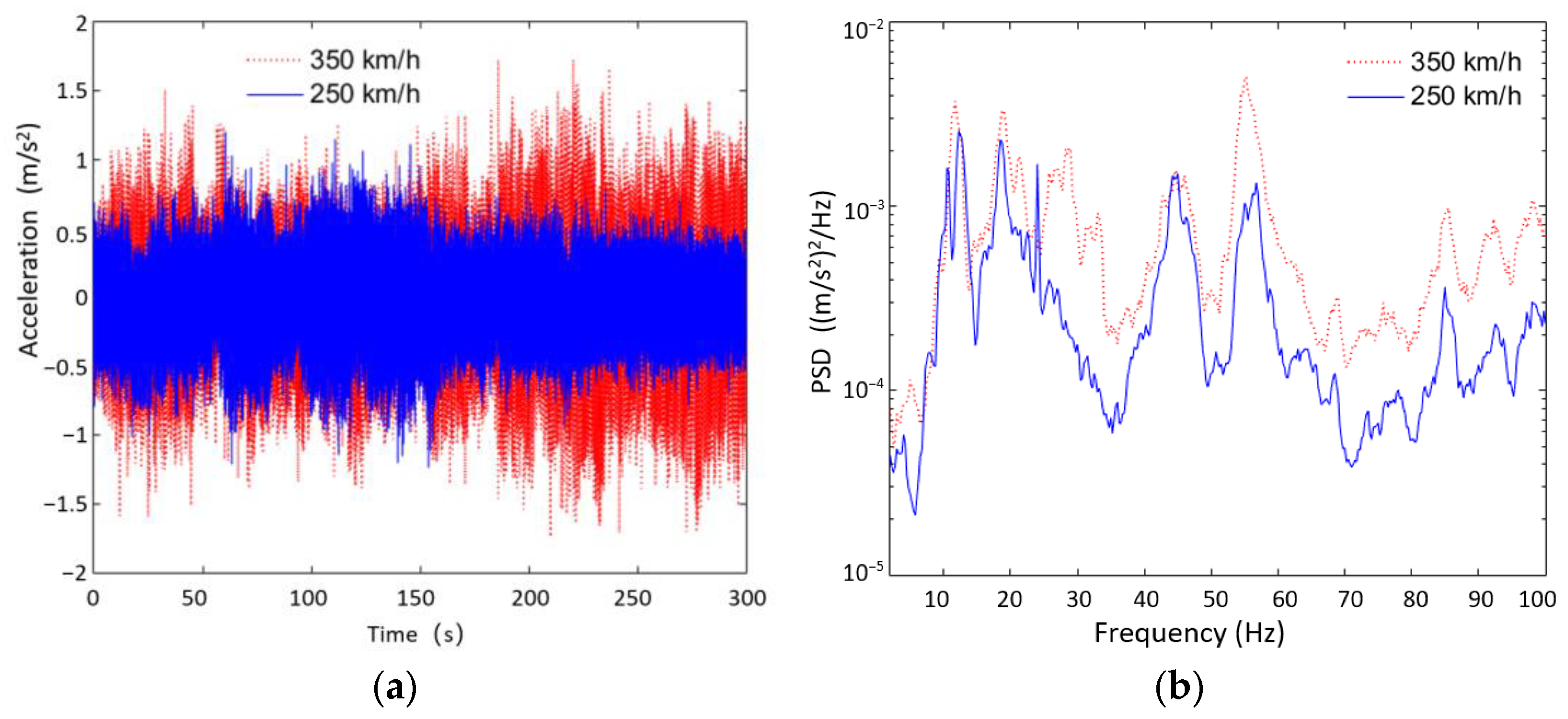
The vibration signal acquisition lasted for 300 s, and the sampling frequency was 512 Hz. Figure 2a and Figure 3a show the vibration signals in the Z-direction measured at the carriage floor and seat cushion for 250 and 350 km/h speeds in time domain. The peak values were mainly excited by the track irregularity. It was found that the vibration transmitted to the seat cushion was greatly attenuated by the seat. When the train speed increased from 250 to 350 km/h, the vibration amplitude of the floor increased significantly by about 50%, while the vibration amplitude of the seat did not increase accordingly. When the train speed increased, the vibration energy of the floor above 20 Hz was significantly enhanced, while the vibration energy of the seat only increased significantly in the 20–30 Hz band. The average vibration acceleration power spectral density curves, shown in Figure 2b and Figure 3b, indicated that the seat had a strong attenuating effect on the vibration of the floor in the 20–100 Hz band, while it became insignificant in the 0.5–20 Hz band.
The detailed test results are analyzed and compared with the simulation results in the following sections.

3. Prediction of Carriage Vibration Based on Rigid–Flex Coupled Dynamics Model

The full-trimmed carriage FE model of the CRH380 series high-speed train was adopted from [6], which was verified by a modal test. The full-trimmed carriage FE model was generally divided into two parts: BIW (body-in-white) part and trim part.
The BIW FE model was discretized by quadrangular and triangular elements consisting of approximately 446,000 elements and 350,000 nodes, as shown in Figure 4a. In the direction from bottom to top, the trim parts included thermal insulation layer, draining board, sound absorption layer, floorboard system, chairs, doors, windows, wooden dividing-walls, glass dividing walls, sidewall panels, luggage racks, and ventilation system. The FE model of the trim part was mainly discretized by hexahedral units consisting of about 320,000 units and 440,000 nodes, as shown in Figure 4b. The BIW body was mainly composed of 7N01 aluminum alloy material. The density of the aluminum alloy material was 2685 kg/m3, the elastic modulus was 72.4 Gpa, and the Poisson’s ratio was 0.3. The material parameters of each component of the trim part were chosen from [6]. The full-trimmed carriage FE model is displayed in Figure 4c.
As the dynamic characteristics of a high-speed train can be analyzed based on rigid–flex coupled model, the elastic processing of the train–rail coupled multibody dynamics model requires the substructure analysis of the carriage. In order to maintain the accuracy of the FE model of the carriage as well as simplify the calculation burden, the main nodes of the substructure were selected as follows.
(1)
The position with large rigidity of BIW was evenly spaced to select the main nodes.
(2)
In order to maintain the outline of the carriage, the main nodes were selected in the center of the walls and top and bottom on both sides of the carriage.
(3)
The main nodes were selected for the suspension installation positions of the two series of pillow beams at the bottom of the carriage for subsequent connection with the bogie.
(4)
The position where the floor and side walls of the carriage were connected to the seat was selected as the main node for subsequent connection to the seat model.
According to the above selection rules, 244 master nodes (marked yellow) were selected during the substructure analysis, and each node retained full degrees of freedom, so the degrees of freedom of the substructure model were 1464, as shown in Figure 4d.
The train–track coupled rigid multibody dynamics model of the CRH380 series high-speed train was adopted from [17], as shown in Figure 5. The rigid carriage in the model was replaced with the elastic substructure model to form a train–track rigid–flex coupled dynamics model. As the carriage was connected to the wheel–rail system through the suspension force of the second series, the influence of the elastic deformation of the carriage on the wheel–rail contact was small, so the influence of the elastic treatment of the carriage on the wheel–rail interaction force could be ignored.
In order to verify the accuracy of the train–track rigid–flex coupled dynamics model, a vibration point was set on the carriage floor at the same position in the test. Simulation with the proposed model at the condition of 350 km/h acquired a 5 s result in the X-, Y-, and Z-directions, which were compared with the test results, as shown in Figure 6.
As the ride comfort is mainly determined by vibrations within 20 Hz, the accuracy of the predicted vibrations within 20 Hz is very important for ride comfort evaluation. The comparison results showed that the vibration peaks within 20 Hz could be accurately obtained with the model. The predicted vibrations were distributed similarly to the measured ones throughout the analysis frequency band, which verified the accuracy of the train–track rigid–flex coupled dynamics model.

4. Seat–Human Body Coupled Dynamics Model of High-Speed Trains

The multibody dynamics method was used to establish the human body dynamics model. The model considered the human body as a total of 17 rigid masses representing head, neck, chest, abdomen, hips, upper arms, forearms, hands, thighs, calves, and feet. The masses of each part were connected to each other by articulation and force units. The inertia parameters (masses and moment inertia of the X-axis (Ixx), the Y-axis (Iyy), and the Z-axis (Izz)) of each part of the human body were obtained from [18,19,20], as shown in Table 1. The abdomen and hips were treated as a mass block and connected to the thighs. The height of the mannequin was set to 175 cm, and the total mass of the human body was 66 kg, which was the same as the experiment.
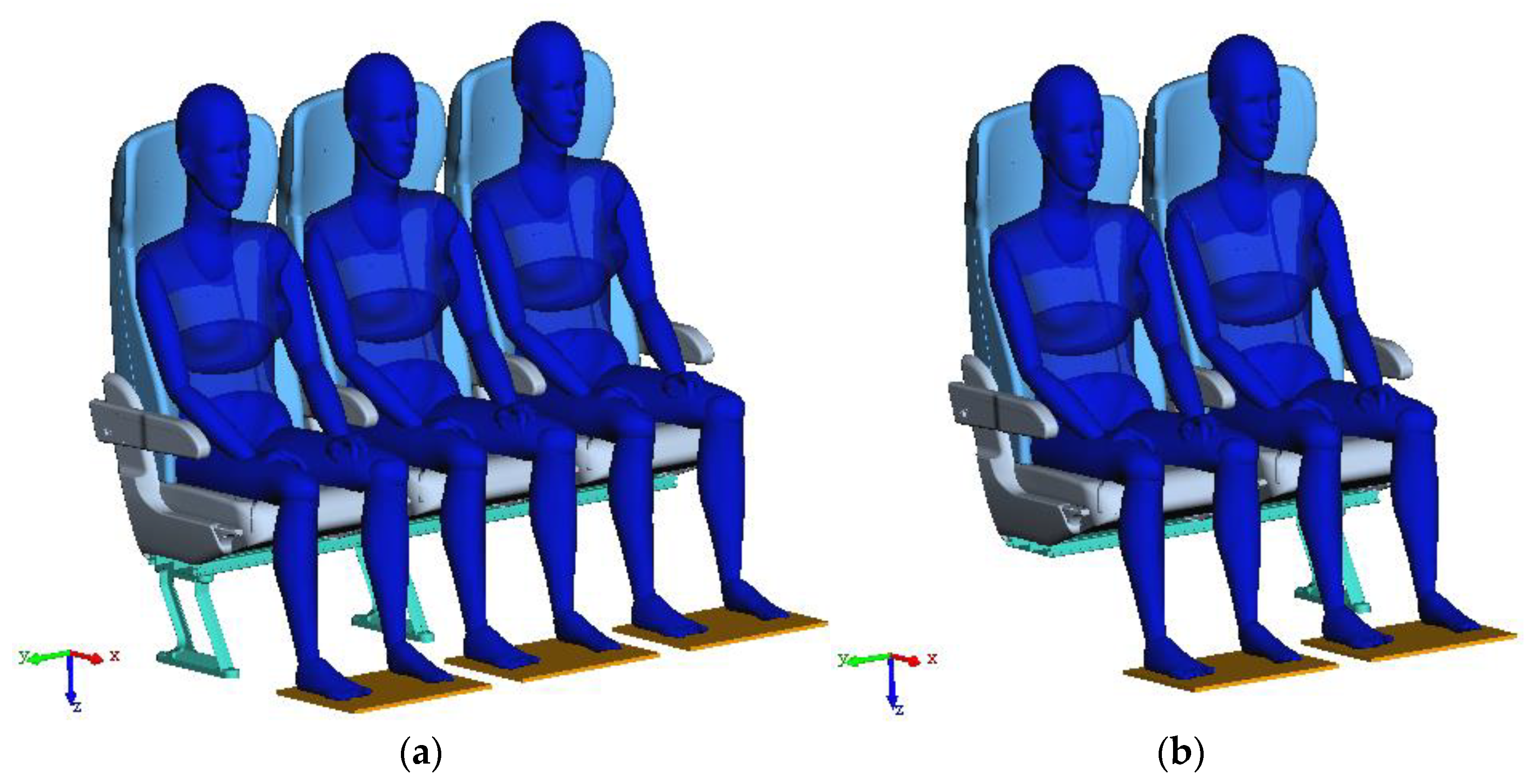
High-speed train seats are composed of two-person seats and three-row seats. The seats can be treated as consisting of multiple single seats, and each single seat is rigidly connected to the bottom seat frame by bolts. The seat frame supports were bolted together with the floor. The multibody dynamics method was used to establish the seat model, and the seat was decomposed into seat frame, seat upholstery, backrest skeleton, backrest upholstery, armrest, bottom frame, and frame bracket. The seat frame and the backrest skeleton were hinged, and the degrees of freedom were constrained to only lateral plane rotation. The seat upholstery and backrest upholstery were connected to the frame by a bushing unit, while rigid connections were applied between the armrests, seat frame, and frame brackets. Table 2 shows the stiffness and damping parameters of the seat, where Kt and Ct represent the translational stiffness and damping, respectively, while Kr and Cr represent the rotational stiffness and damping, respectively. Then, the high-speed train seat–human body coupled dynamics model was established for the three-seat seat–human body coupled dynamics model and the two-seat seat–human body coupled dynamics model, as shown in Figure 7.
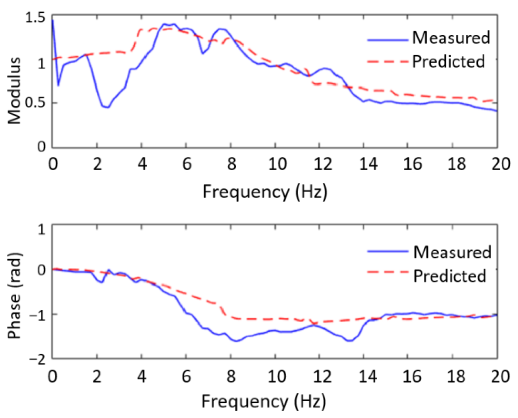
In order to verify the accuracy of the seat–human body coupled dynamics model, 0–20 Hz sweep frequency excitation with intensity of 0.5 m/s2 r.m.s. was applied at the bolted junction between the seat and the floor, and the duration was 20 s. The experimental results were from the on-site vibration test outlined in Section 2. In the simulation, measuring points were set at the interface between human body and seat cushion. The vibration transmissibility of the seat obtained with the model was compared with the measured results, as shown in Figure 8.
The comparison results showed that the seat model captured the peak in the transmissibility of the Z-direction vibration around 5 Hz, and the predicted modulus in the frequency range of 5–20 Hz was close to the test results. As the energy within the 5 Hz may not have been strong enough to excite the response of the seat in the test, the predicted values within 5 Hz were larger than the test results. In addition, the comparison of the phase results also showed that the predicted results were basically consistent with the test results. The above analysis indicated that the seat–human body coupled dynamics model could be used for subsequent vibration comfort analysis.

5. Prediction of Dynamic Ride Comfort of High-Speed Train

5.1. Train Seat–Human Body Coupled Dynamics Model

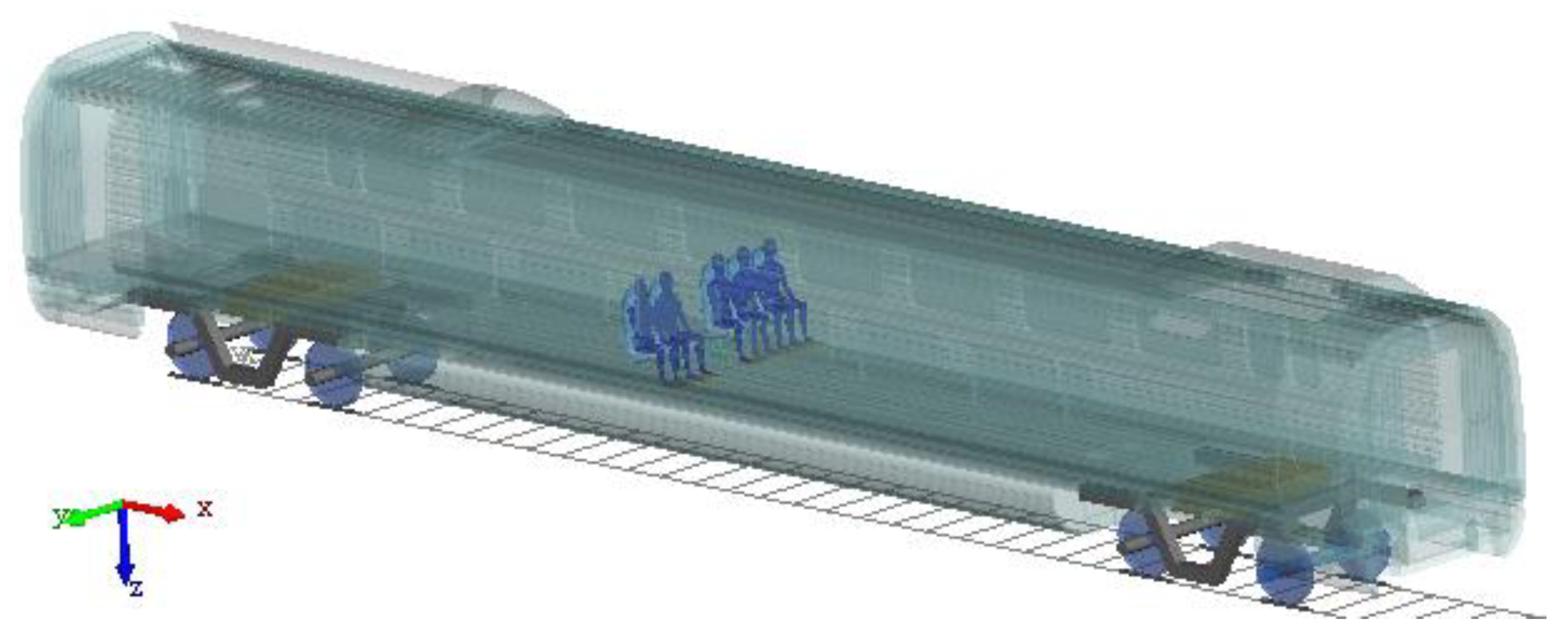
The train seat–human body coupled dynamics model was established to predict the ride comfort of high-speed trains based on the train–track rigid–flex coupled dynamics model and seat–human body coupled dynamics model. In the model, the structure of the track, wheelset, and bogie were established as a multibody dynamics model. The carriage was established as an elastomer model, and the seat and human body were established as a multibody dynamics model. The seat–human body coupled model was installed in the middle of the carriage, as shown in Figure 9.
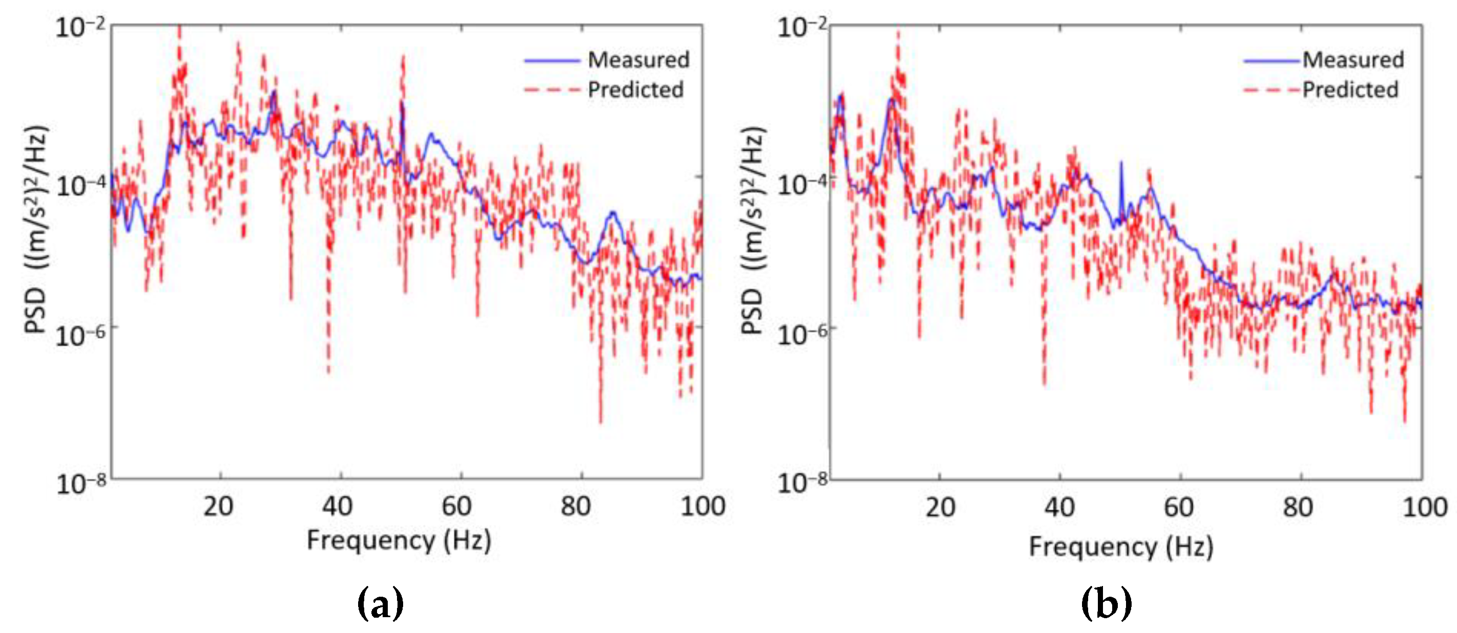
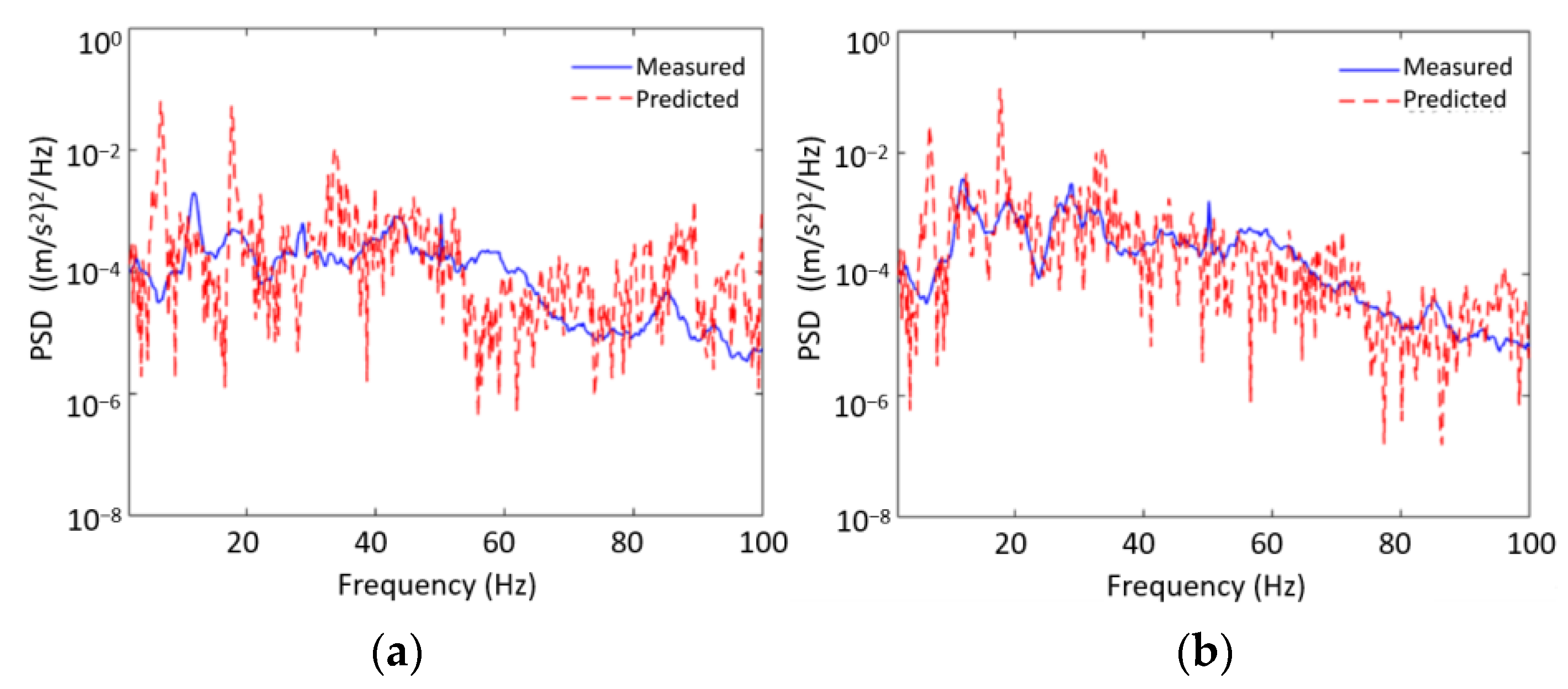
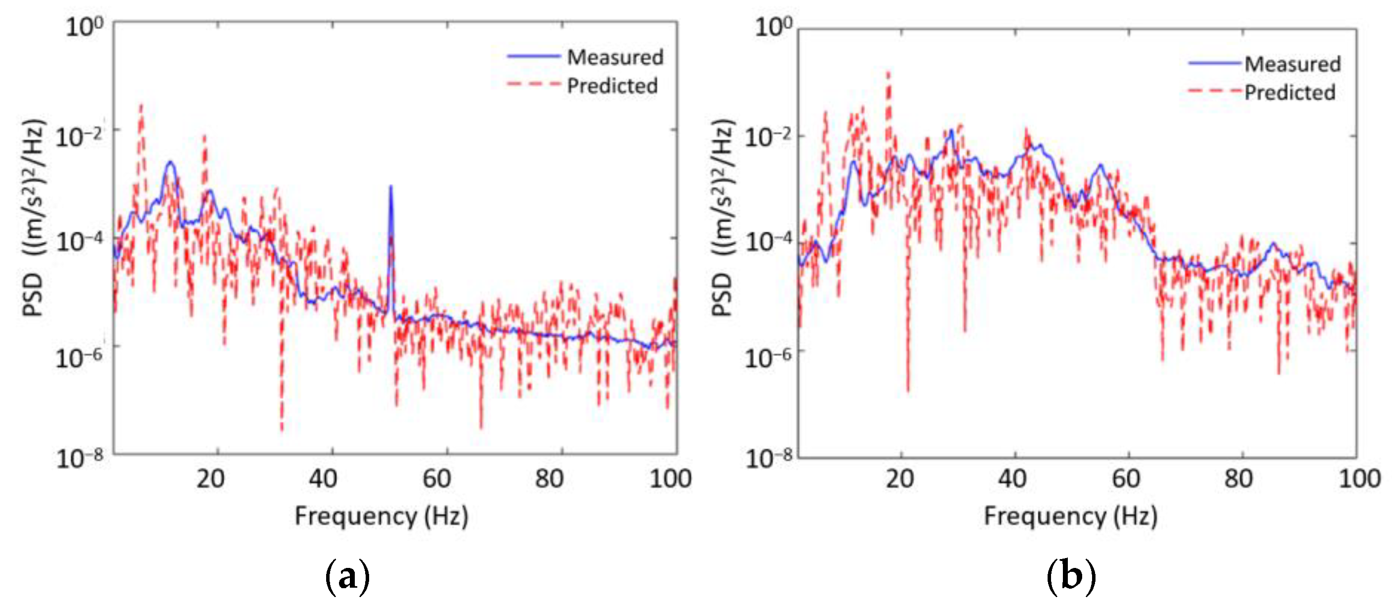
A comparison between the predicted and measured acceleration of the seat was carried out to verify the accuracy of the train seat–human body coupled dynamics model of high-speed trains. The power spectral density (PSD) of track irregularity of Chinese high-speed railway was applied to the model at the speeds of 250 and 350 km/h. The detailed calculation method, fitting function, and fitting spectrum of PSD of track irregularity can be found in [21], which has also become the main part of the national railway standard of China as TB\T3352: 2014. The simulated seat vibration accelerations were collected at the interface between the human body and the seat cushion. Simulation lasted for 5 s with a sampling frequency of 512 Hz.
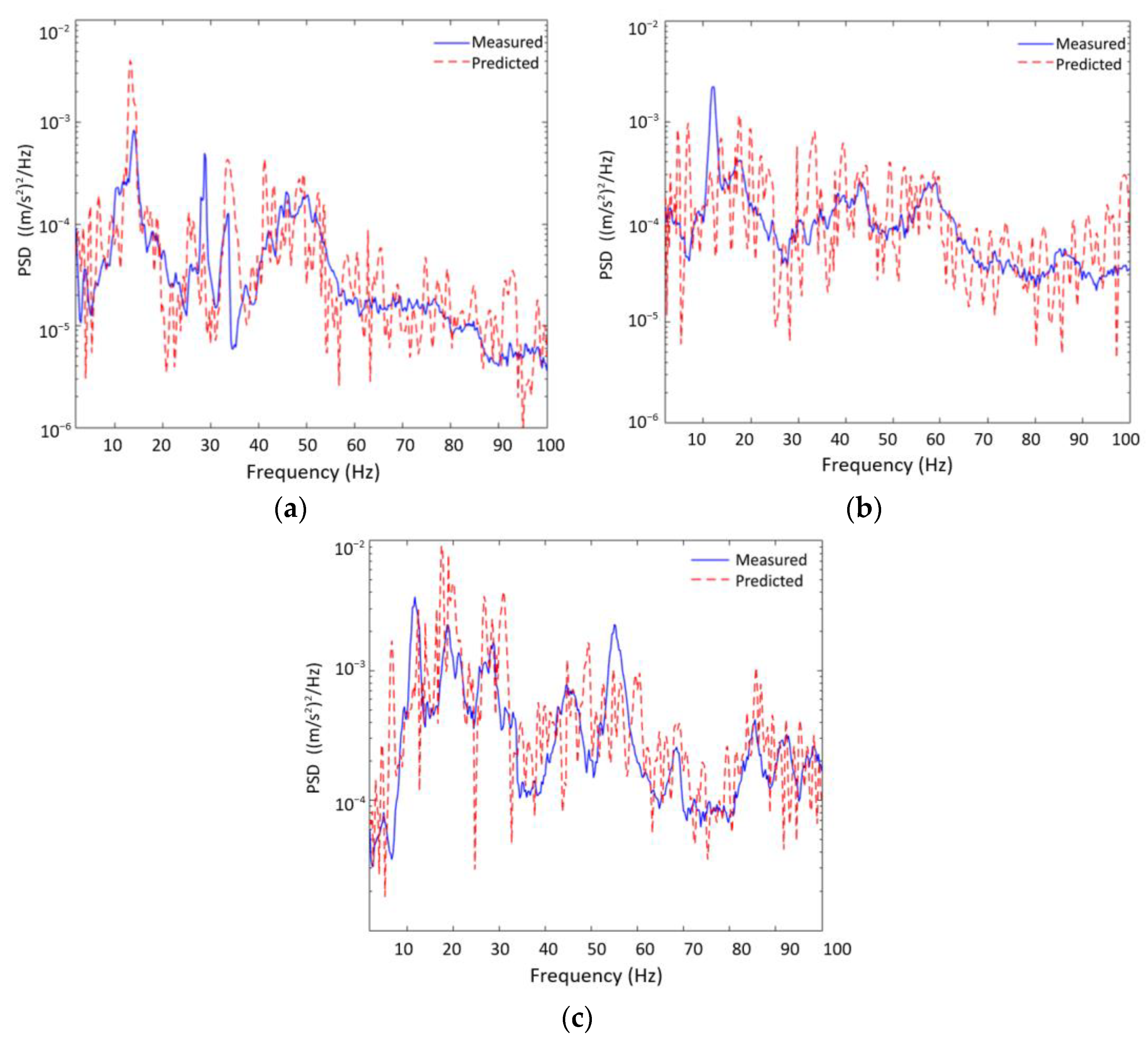
The comparisons of seat vibration spectrums in the X-, Y-, and Z-directions were shown in Figure 10, Figure 11 and Figure 12. The results showed that the vibration peaks (e.g., 15, 20, and 50 Hz) in different directions of the seat could be accurately captured by the proposed coupled dynamics model. As the vibration peaks represented the vibration response of the interface between human body and seat cushion, it could be inferred that the proposed model represented the dynamic characteristics of the coupled system. Although the errors of the simulation model might have caused fluctuations in the frequency domain, the overall trends were basically consistent with the experimental results in the analysis frequency band. In addition, the r.m.s. value of the error in different directions were all less than 10%, which indicated the accuracy of the train seat–human body coupled dynamics model. In conclusion, the proposed model can be used for the prediction of dynamic ride comfort of high-speed trains.

5.2. Evaluation Method for Dynamic Ride Comfort

As the British Standard BS EN 12299:2009 [15] improved the weighting curve for rail vehicles proposed by the ISO 2631:2-2003, which gave an evaluation scheme for train floor, seat, and backrest, the BS EN 12299:2009 standard was used to evaluate the dynamic ride comfort of high-speed trains.
The evaluation method by BS EN 12299:2009 requires measuring the vibration of the train floor and seat surface, uses a specified frequency weighting filter, and intercepts the time domain with a time length of 5 s. As shown in Table 3, BS EN 12299:2009 proposes four frequency-weighted functions. For the application in high-speed trains, Wb is the weighted Z-direction vibration of the floor and seat cushion, Wc is the weighted X-direction vibration of the backrest, Wd is the weighted X- and Y-direction vibration of the floor and Y-direction vibration of the seat cushion, and Wp is the weighted X-direction vibration of the floor vibration. Detailed information about the four frequency-weighted functions are presented clearly in Annex C of the standard BS EN 12299:2009 [15].
After calculating the r.m.s. weighted acceleration values for different directions at each position, the vibration comfort of the carriage floor (NMV) and the ride comfort of the seated passenger (NVA) were evaluated separately. The comfort evaluation and grading of the vibration comfort indicators of the carriage in different ranges are shown in Table 3. As ride comfort is greatly affected by individual subjectivity and there is no specific evaluation standard, it was also evaluated in the same evaluation scale as the vibration comfort of the carriage floor.
The experimental results obtained in Section 2 and the predicted results by the proposed train seat–human body coupled dynamics model were used to calculate the weighted r.m.s. accelerations and ride comfort indicators NVA for 350 km/h based on BS EN 12299:2009, as shown in Table 4. The predicted NVA was 1.28 m/s2 and the measured value was 1.29 m/s2, with a prediction error of 2.3%, which further verified the accuracy of the proposed train seat–human body coupled dynamics model.
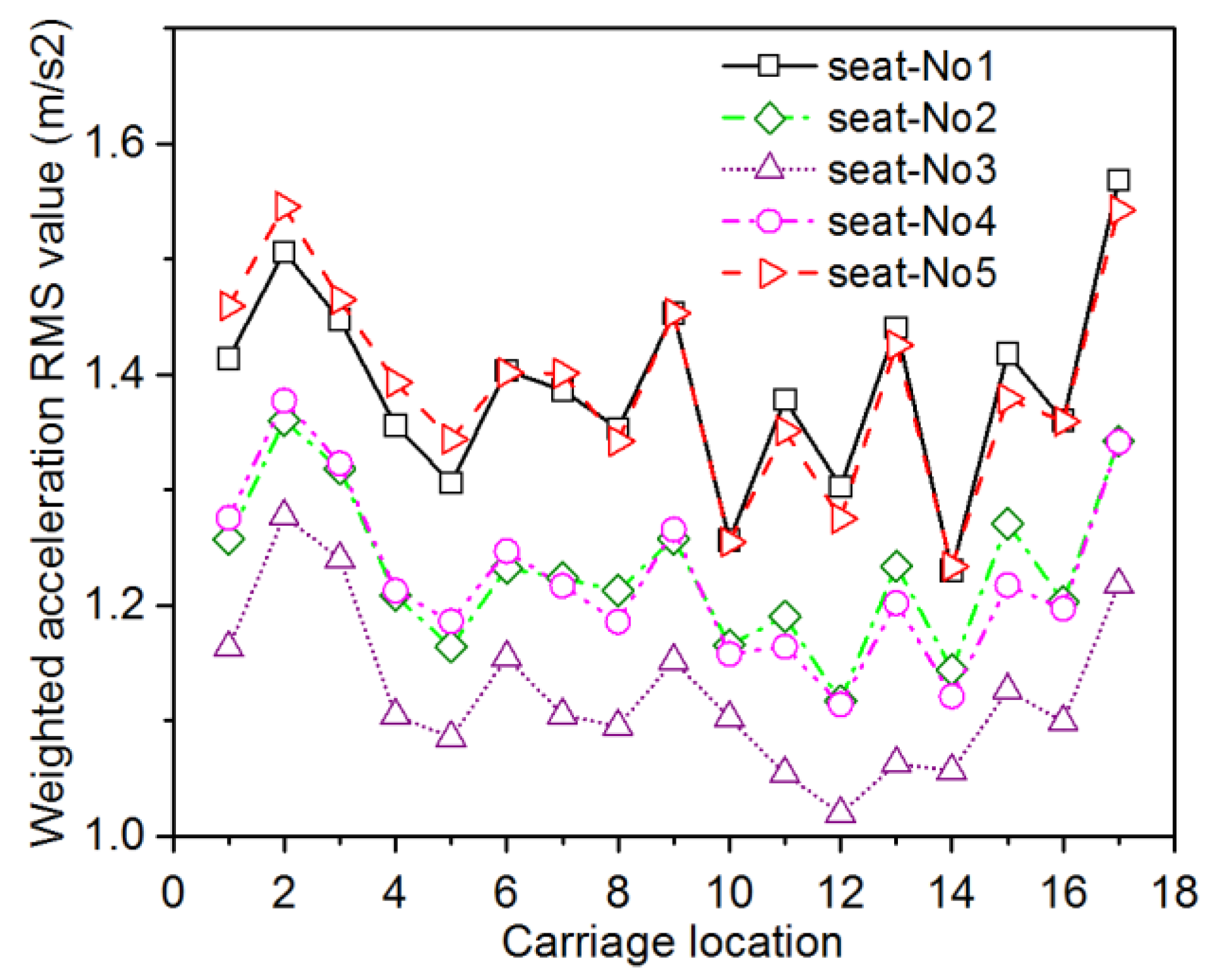
In order to study the distribution of ride comfort, the position of seat–human body coupled dynamics model was changed, and the response of each seat was obtained for 350 km/h. There were 17 rows of seats in the carriage of the high-speed train. For convenience of research, seats were numbered 1–17 longitudinally from rear to front, and the lateral seats of the carriage were numbered No.1–No.5 from left to right. The results are shown in Figure 13.
It can be seen that the values of NVA of seat No.1 and No.5 were significantly greater than those in other positions, and the NVA of seat No.3 was the smallest in the entire longitudinal orientation, which indicated that the seats in the lateral position of the carriage near the side wall performed the worst on ride comfort and the seat in the middle of the carriage were the best.
The longitudinal distribution results showed that the carriage had a NVA value less than 1.5 m/s2 in most seating positions with a “very comfortable” ride comfort rating, except for the longitudinal row numbers 1–3 and 16–17 seating positions, which corresponded to the front and rear steering areas and close to the position where the suspension force of the second series was applied.

5.3. The Effect of Seat Cushion Stiffness and Damping on Ride Comfort

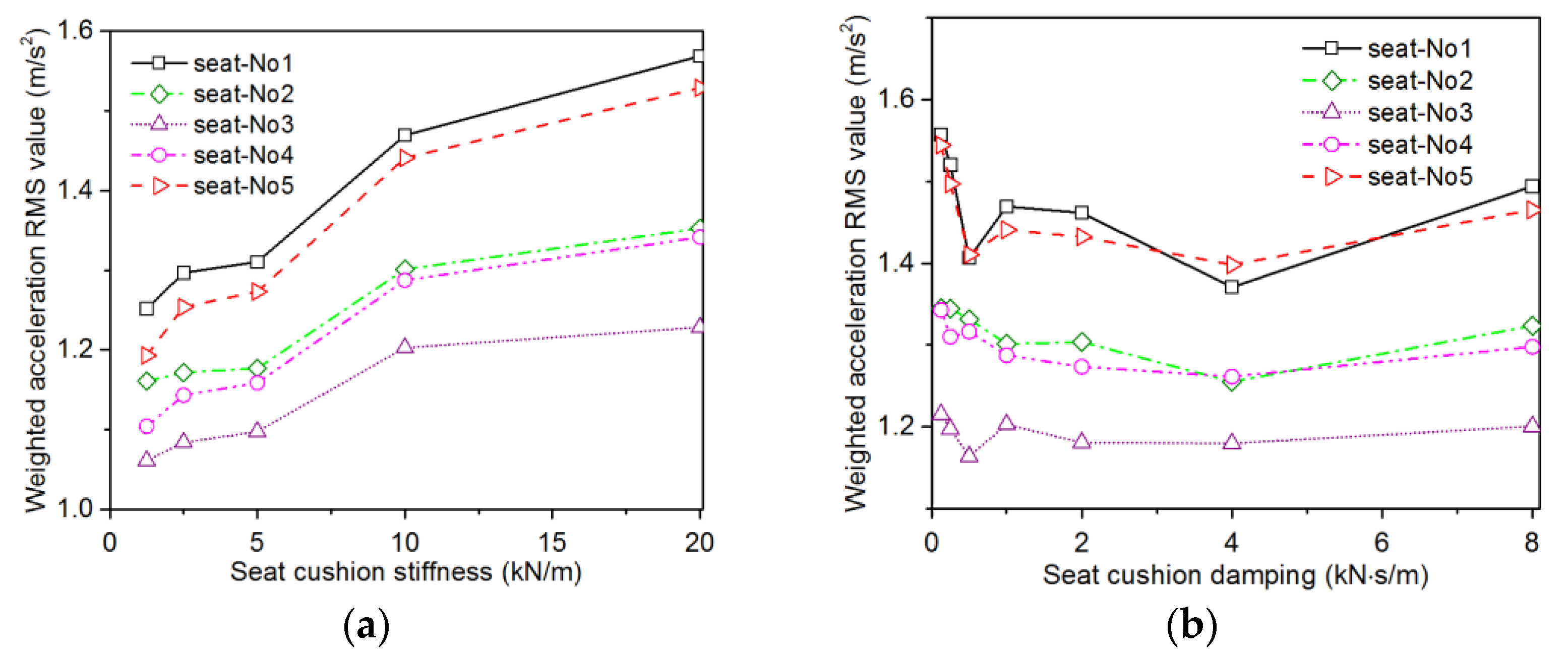
Experimental studies related to the subjective and objective comfort of seats have shown that ride comfort is closely related to seat cushion stiffness and damping parameters [22]. To study the effects of seat cushion stiffness and damping on ride comfort, simulations were carried out by setting the stiffness as 1.25, 2.5, 5, 10, and 20 kN/m and damping as 0.125, 0.25, 0.5, 1, 2, 4, and 8 N·s/m.
The seats in the middle of the carriage were selected for analysis. Figure 14a shows the values of NVA changing with the stiffness of the seat cushion in different lateral positions. As the seat cushion stiffness increased, the NVA value gradually increased, indicating decreasing ride comfort. When the seat cushion stiffness was low, differences between the values of NVA at the side wall position and the middle position gradually increased with the increase in stiffness, which indicated that the ride comfort near the side wall was more sensitive to changes in the seat cushion stiffness.
Figure 14b shows the variation of NVA in different lateral positions with the change of seat cushion damping. When the seat cushion damping was less than 4 kN·s/m, the NVA value gradually decreased with the increase in damping. In contrast, when the damping was greater than 4 kN·s/m, the NVA value increased with the increase in damping. As the seat cushion damping attenuated the vibration transmitted by the seat frame to the human body, in the case of small damping, the damping increase could effectively suppress the transmission of low-frequency vibration to the human body, while in the case of large damping, the damping increase could not suppress the transmission of high-frequency vibrations.

6. Conclusions

In this paper, a train seat–human body coupled dynamics model was established to predict the ride comfort of high-speed trains based on the train–track rigid–flex coupled dynamics model and seat–human body coupled dynamics model. The conclusions can be summarized as follows:
  • The accuracy of the proposed train seat–human body coupled dynamics model and its submodels were separately verified by the test results. The results showed that the vibration peaks in different directions of the seat could be accurately captured by the proposed coupled dynamics model, and the overall trends were basically consistent with the test results in the analysis frequency band. The r.m.s. value of the error in different directions were all less than 10%, which indicated that the proposed model can be used for the prediction of ride comfort of high-speed trains.
  • The standard BS EN 12299:2009 was used to evaluate the ride comfort of high-speed trains. The predicted results showed that the seats in the middle of the carriage had the best comfort performance, while those near the side wall and close to the position where the suspension force of the second series was acting were less comfortable.
  • The influence of seat stiffness and damping parameters on the ride comfort of the seat was analyzed, and the results showed that the ride comfort deteriorated with the increase in seat cushion stiffness. As the cushion damping increased, the ride comfort first got better and then deteriorated.
  • The proposed train seat–human body coupled dynamics model should provide good guidance for the future development of ride comfort in high-speed trains.

Author Contributions

This article was prepared through the collective efforts of all the authors. Conceptualization, methodology, software, and original draft preparation, H.L.; funding acquisition, resources, and supervision, Y.Q. and X.Z.; validation, W.D. and H.L.; writing—review and editing, H.L., X.Z., W.D. and Y.Q. All authors have read and agreed to the published version of the manuscript.

Funding

This research was funded by the National Natural Science Foundation of China grant number 51975515.

Institutional Review Board Statement

Not applicable.

Informed Consent Statement

Not applicable.

Data Availability Statement

Not applicable.

Conflicts of Interest

The authors declare no conflict of interest.

References

  1. Suzuki, H. Research trends on riding comfort evaluation in Japan. proceedings of the institution of mechanical engineers. Proc. Inst. Mech. Eng. Part F-J. Rail Rapid Transit 1998, 212, 61–72. [Google Scholar] [CrossRef]
  2. Zhou, J.; Goodall, R.M.; Ren, L.; Zhang, H. Influences of car body vertical flexibility on ride quality of passenger railway vehicles. Proc. Inst. Mech. Eng. Part F-J. Rail Rapid Transit 2009, 223, 461–471. [Google Scholar] [CrossRef] [Green Version]
  3. Sun, W.; Zhou, J.; Thompson, D.; Gong, D. Vertical random vibration analysis of vehicle track coupled system using green’s function method. Veh. Syst. Dyn. 2014, 52, 362–389. [Google Scholar] [CrossRef]
  4. Cao, H.; Zhang, W.; Miao, B. Vertical vibration analysis of the flexible carbody of high speed train. Int. J. Veh. Struct. Syst. 2015, 7, 55–60. [Google Scholar]
  5. Tomioka, T.; Takigami, T.; Suzuki, Y. Numerical analysis of three-dimensional flexural vibration of railway vehicle car body. Veh. Syst. Dyn. 2006, 44 (Suppl. 1), 272–285. [Google Scholar] [CrossRef]
  6. Zheng, X.; Hao, Z.; Wang, X.; Mao, J. A full-spectrum analysis of high-speed train interior noise under multi-physical-field coupling excitations. Mech. Syst. Signal Process. 2016, 75, 525–543. [Google Scholar] [CrossRef]
  7. Gialleonardo, E.D.; Braghin, F.; Bruni, S. The influence of track modelling options on the simulation of rail vehicle dynamics. J. Sound Vib. 2012, 331, 4246–4258. [Google Scholar] [CrossRef]
  8. Carlbom, P.; Hermodsson, M.; Borg, J.; Norman, M.; Andersson, H. Carbody and Passengers in Rail Vehicle Dynamics. Ph.D. Thesis, Institutionen för Farkostteknik, Stockholm, Sweden, 2000. [Google Scholar]
  9. Liu, C.; Qiu, Y. Mechanism associated with the effect of backrest inclination on biodynamic responses of the human body sitting on a rigid seat exposed to vertical vibration. J. Sound Vib. 2021, 510, 116299. [Google Scholar] [CrossRef]
  10. Wu, J.; Qiu, Y. Modeling and analysis of a train seat with occupant exposed to combined lateral, vertical and roll vibration. J. Sound Vib. 2021, 496, 115920. [Google Scholar] [CrossRef]
  11. Wu, J.; Qiu, Y. Analysis of ride comfort of high-speed train based on a train-seat-human model in the vertical direction. Veh. Syst. Dyn. 2021, 59, 1867–1893. [Google Scholar] [CrossRef]
  12. Kumar, V.; Rastogi, V.; Pathak, P.M. Simulation for whole-body vibration to assess ride comfort of a low-medium speed railway vehicle. Simul. Trans. Soc. Model. Simul. Int. 2016, 93, 225–236. [Google Scholar] [CrossRef]
  13. Lin, Z.; Zhang, J.; Li, M.; Zhuang, Y.; Liu, C.; Lin, J. Biodynamic response of seated human body to roll vibration: Effect of armrest support. J. Sound Vib. 2022, 529, 116939. [Google Scholar] [CrossRef]
  14. Wu, J.; Qiu, Y. Modelling and ride comfort analysis of a coupled track-train-seat-human model with lateral, vertical and roll vibrations. Veh. Syst. Dyn. 2022, 60, 2988–3023. [Google Scholar] [CrossRef]
  15. British Standards Institution. Railway Applications—Ride Comfort for Passengers—Measurement and Evaluation; British Standards Institution: London, UK, 2009; p. 12299. [Google Scholar]
  16. ISO 10326-2; Mechanical vibration—Laboratory method for evaluating vehicle seat vibration—Part 2, Application to railway vehicles. International Organization for Standardization: Geneva, Switzerland, 2001.
  17. Dai, W.; Zheng, X.; Luo, L.; Hao, Z.; Qiu, Y. Prediction of high-speed train full-spectrum interior noise using statistical vibration and acoustic energy flow. Appl. Acoust. 2019, 145, 205–219. [Google Scholar] [CrossRef]
  18. Lin, Y.; Wang, M.J.; Wang, E.M. The comparisons of anthropometric characteristics among four peoples in East Asia. Appl. Ergon. 2004, 35, 173–178. [Google Scholar] [CrossRef] [PubMed]
  19. Hui, X.; Xiuyuan, Z.; Xuanliang, D.; Donghong, H.; Qin, L.; Hong, L.; Jingmin, L.; Wei, L. A research on the body center of mass of Chinese adults. Int. J. Ind. Ergon. 1999, 23, 129–133. [Google Scholar] [CrossRef]
  20. Cheng, C.K.; Chen, H.H.; Chen, C.S.; Lee, C.L.; Chen, C.Y. Segment inertial properties of Chinese adults determined from magnetic resonance imaging. Clin. Biomech. 2000, 15, 559–566. [Google Scholar] [CrossRef] [PubMed]
  21. Kang, X.; Liu, X.; Li, H.; Yang, F.; Gao, J.; Zhai, W. PSD of ballastless track irregularities of high-speed railway. Sci. Sin. Technol. 2014, 44, 687–696. [Google Scholar]
  22. Speed, G.; Harris, K.; Keegel, T. The effect of cushioning materials on musculoskeletal discomfort and fatigue during prolonged standing at work: A systematic review. Appl. Ergon. 2018, 70, 300–314. [Google Scholar] [CrossRef] [PubMed]
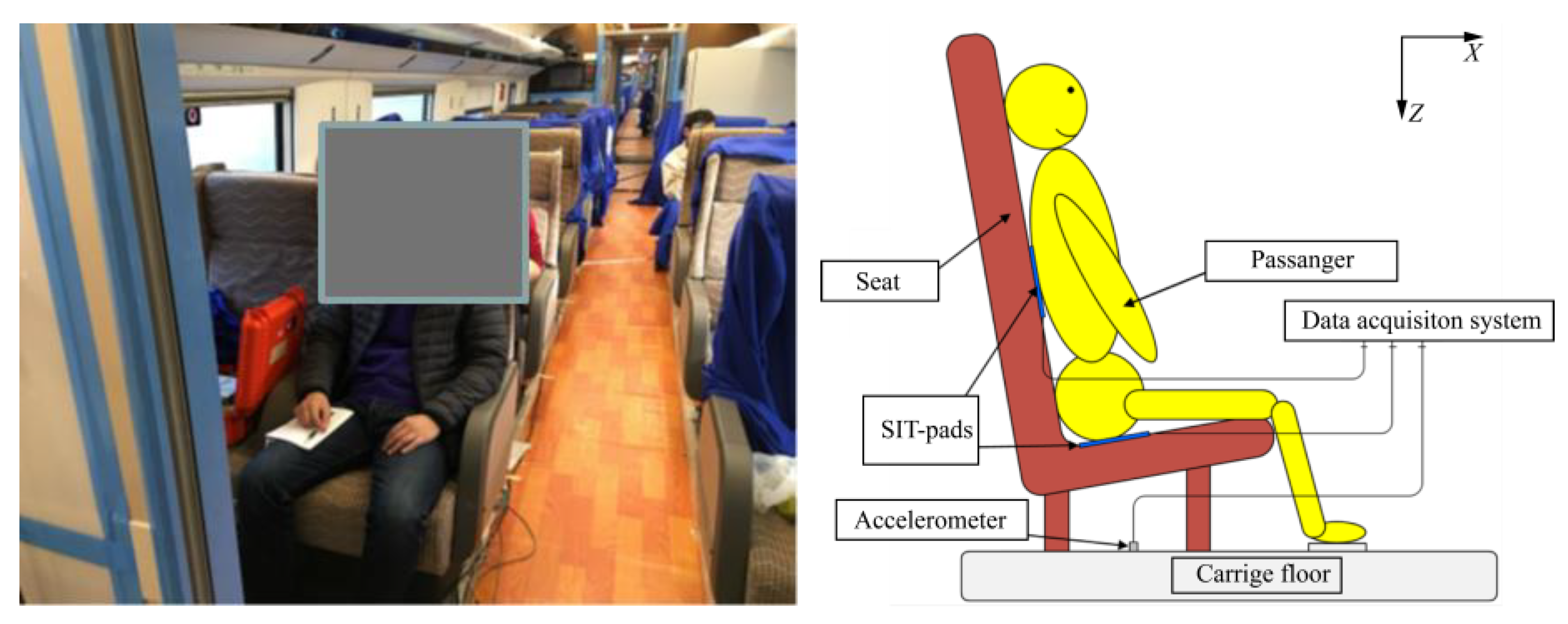
Figure 1. On-site vibration test in a high-speed train.
Applsci 12 12900 g001
Figure 2. Z-direction acceleration measured at the carriage floor. (a) Signals in time domain; (b) power spectral density.
Applsci 12 12900 g002
Figure 3. Z-direction acceleration measured at the seat pan. (a) Signals in time domain; (b) power spectral density.
Applsci 12 12900 g003
Figure 4. FE model of the carriage. (a) FE model of BIW; (b) trim parts; (c) full-trimmed carriage assembly; (d) main node of the carriage substructure.
Applsci 12 12900 g004
Figure 5. The train–track coupled rigid multibody dynamics model.
Applsci 12 12900 g005
Figure 6. Comparisons between the predicted and measured PSDs of the acceleration of the carriage floor. (a) X-direction; (b) Y-direction; (c) Z-direction.
Applsci 12 12900 g006
Figure 7. Seat–human body coupled dynamics model of high-speed trains. (a) Three-seat model; (b) two-seat model.
Applsci 12 12900 g007
Figure 8. The modulus and phase of the Z-direction transmissibility of the seat.
Applsci 12 12900 g008
Figure 9. Train seat–human body coupled dynamics model.
Applsci 12 12900 g009
Figure 10. Power spectral density of seat acceleration in X-direction. (a) 350 km/h; (b) 250 km/h.
Applsci 12 12900 g010
Figure 11. Power spectral density of seat acceleration in Y-direction. (a) 350 km/h; (b) 250 km/h.
Applsci 12 12900 g011
Figure 12. Power spectral density of seat acceleration in Z-direction. (a) 350 km/h; (b) 250 km/h.
Applsci 12 12900 g012
Figure 13. The distribution of the values of ride comfort parameter NVA in the carriage.
Applsci 12 12900 g013
Figure 14. Effect of seat cushion parameters on ride comfort parameter NVA. (a) Stiffness effect; (b) damping effect.
Applsci 12 12900 g014
Table 1. Ratio of mass distribution and moment of inertia of various parts of the human body.
PlaceMass Distribution PercentagePart Mass (kg)Ixx (kg·m²)Iyy (kg·m²)Izz (kg·m²)
Head + neck8.62%5.690.0360.0370.016
torso44.05%29.070.940.990.18
Upper arm2.43%1.600.0270.0260.0025
Forearm1.25%0.830.00670.00660.0007
Hand0.64%0.420.00100.00090.002
Thigh14.19%9.370.140.140.017
Calf3.67%2.420.0250.0250.003
Feet1.48%0.980.0090.0070.009
Abdomen and hips23.67%15.62
Table 2. High-speed train seat parameters.
PlaceKt
(N/m)
Kr
(N·m/rad)
Ct
(N·s/m)
Cr
(N·m·s/rad)
Seat cushion10,000350100035
Seat bracket10,000300100030
Table 3. Carriage vibration comfort index NMV evaluation grading range [15].
Range (m/s2).Evaluation
NMV < 1.5Very comfortable
1.5 ≤ NMV < 2.5Comfortable
2.5 ≤ NMV < 3.5Medium
3.5 ≤ NMV < 4.5Uncomfortable
NMV ≥ 4.5Very uncomfortable
Table 4. Weighted r.m.s. acceleration and predicted ride comfort indicator NVA.
Floor Z-Direction (m/s2).Seat Cushion Y-Direction (m/s2)Seat Cushion Z-Direction (m/s2)Backrest X-Direction (m/s2).NVA
(m/s2)
Measured0.16310.11760.10530.05781.29
Predicted0.18190.13200.1330.04651.28
Publisher’s Note: MDPI stays neutral with regard to jurisdictional claims in published maps and institutional affiliations.