Article

Deep Drawing of AISI 304 Blanks with Polymer Punches Produced by Additive Manufacturing: Effects of Process Scalability

Advanced Prototype Laboratory, Mechanical and Industrial Department, University of Brescia, 25123 Brescia, Italy
Appl. Sci. 2022, 12(24), 12716; https://doi.org/10.3390/app122412716
Submission received: 10 November 2022 / Revised: 3 December 2022 / Accepted: 8 December 2022 / Published: 12 December 2022
(This article belongs to the Section Additive Manufacturing Technologies)

Abstract

:
Rapid tooling is a methodology which aims to integrate additive manufacturing into the production of tools to be used in casting, forming or machining processes. In forming, rapid tooling is applied in the production of metallic or plastic tools that guarantee good performance in small- and medium-sized batch production. However, most punches tested to date have dimensions measured in millimeters and are therefore unsuitable for typical real-world industrial processes. In this study, the performance of plastic punches with geometries designed for industrial application was investigated. A deep drawing process involving AISI 304 blanks was created for the manufacturing of cups. Experimental and numerical analyses were conducted to measure the quality of the cups produced and the behaviour of the punches involved. The results indicate that when punch dimensions increase, a more precise cup geometry is produced (99% of drawing depth, 98% of cup precision on the fillet radius, and roundness error equal to 0.53%).

1. Introduction

Manufacturing organizations are being forced to adopt new production techniques as a result of intense market competition, dynamic customer demands, environmental laws, and advances in technology [1]. More demanding customer requirements and greater organizational pressures have increased the need for more customized products and processes in the manufacturing sector. Additive manufacturing (AM) technologies may offer a flexible and cost-effective means of meeting these challenges [2]. Rapid tooling (RT) is a methodology which involves the application of AM in the production of small- and medium-sized batches of plastic or metallic tools [3,4]. RT is a natural extension of AM; it originated from the need to assess the performance of AM models. To enable performance validation, such models (prototypes) must be produced using the same material and production process used for full-scale production [5,6]. Today, the main application of RT in conventional production processes is in casting, where it is used in complex-shape and net-shape manufacturing [7,8]. It is also used in injection moulding, to increase process flexibility and reconfigurability [9,10], and in forming, to reduce process costs and production times [11,12]. To increase awareness of the application of RT in conventional processes, the present study focused on the use of carbon-reinforced polymers to produce tooling for deep drawing applications with fused filament fabrication (FFF) technology.
Many researchers have tested the performance of plastic tools in sheet metal processes. Liewald et al. tested polymeric die materials in sheet metal forming and found that by using polymeric materials with high mechanical properties it was possible to produce parts with a dimensional accuracy sufficient for most applications, even using high-strength steels. [13]. Kuo et al. fabricated sheet metal forming dies in epoxy resin filled with zirconia (ZrO2) to deform Al-Mg alloy blanks; their results demonstrated a forming capacity at a thickness of 0.35 mm [14]. Schuh et al. tested PLA punches with different internal fill patterns to draw steel blanks of 1 mm thickness to a depth of 10 mm. In terms of sheet formability, their performance was similar to that of conventional tools. The performance of polymer materials has also been tested by other researchers, and good friction properties have been reported [15]. Frohn-Sörensen et al. used FFF technology to investigate the suitability of a conventional PLA to produce tools for rubber-pad forming of metal blanks. Blanks were of 0.7 mm thickness, punch diameter was 60 mm, and drawing depth was 10 mm. A small-sized batch (64 parts) was produced, and results indicated good performance overall, though some loss of accuracy was recorded in the fillet radius due to the drawing force [16]. In [17], the authors used PLA tools to produce 30 pieces of hemispherical steel cups with a radius of 25 mm. The internal design of the tools was optimized using a topology-optimization technique which reduced weight by up to 30%. Bergweiler et al. investigated the drawing performance of two different materials: PLA; and PA filled with carbon (CF-PA). Steel blanks were formed with punches of 25 mm diameter, and higher accuracy was obtained using the CF-PA material [18]. De Souza et al. proposed a method to evaluate the effects of wear and the friction characteristics of polymer composites on sheet metal forming [19]. To better understand the mechanical behaviour of plastic punches, Frohn-Sörensen et al. tested the compressive and flexural mechanical properties of PLA, polycarbonate, nylon and PETG cylinders made using FFF. Their results revealed significant effects of different materials and different layer heights on properties such as flexural and compressive strength and modulus, as well as density, hardness, and surface roughness [20].
Published results in the literature show that polymer punches can be used in sheet metal forming for both aluminum and steel alloy. However, the laboratory experiments carried out to date have typically involved punches with a diameter of less than 50 mm. In the real-world industrial environment, the diameters of punches are usually higher than 100 mm. Taking this fact as a starting point, the author here presents a study on the performance scalability of polymer punches produced with FFF technology. Two different punch geometries were designed: the first with a diameter similar to that of punches already tested and reported in the literature; the second with a diameter three times higher. Experimental and numerical analyses were then carried out to determine process accuracy and stresses undergone. The results demonstrate that scalability leads to improved process performance.

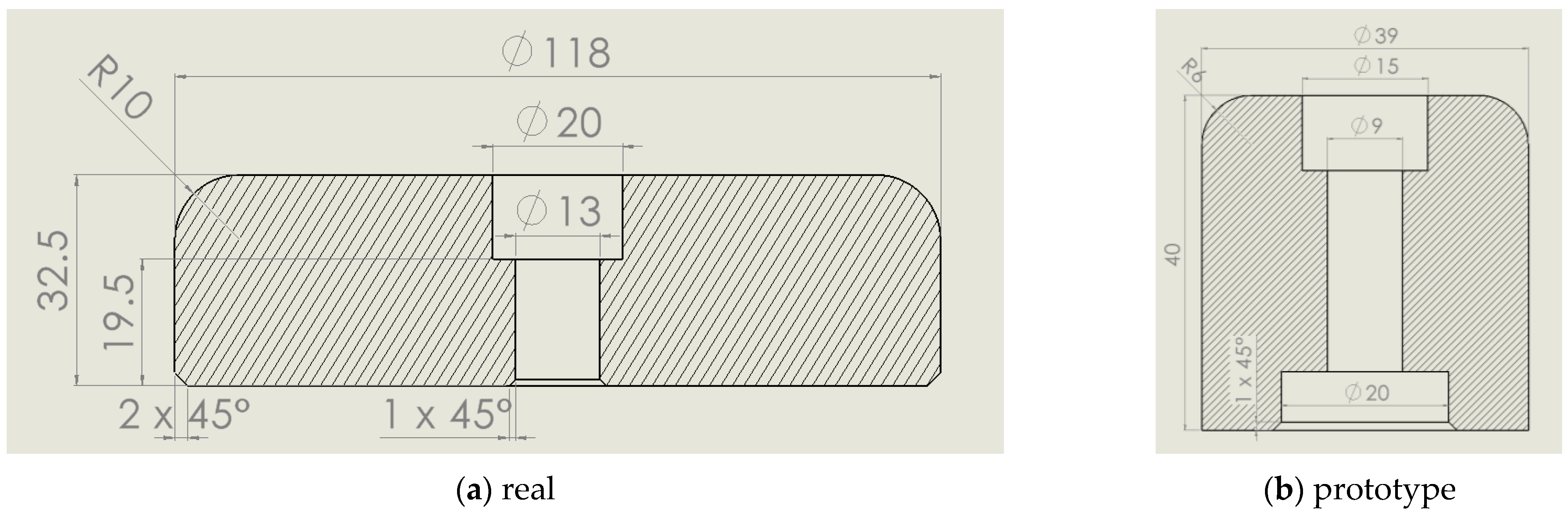
2. Materials and Methods

2.1. Materials

The punch geometry set for the experimental tests consisted of a hollow cylinder with a fillet radius on the face in contact with the blanks. The hollow geometry was designed to enable a mechanical connection by means of a screw between punch and press. To test the capability of the process, two geometries were used: a first, termed real geometry (RG), with an external diameter of 118 mm, similar to that found in real-world manufacturing applications; and a second, termed prototype geometry (PG), with an external diameter of 39 mm. Both geometries are depicted in Figure 1.
Table 1 lists the process parameters of the tool geometries tested. It can be seen that both had the same drawing ratio of 1:8. All other parameters were determined with reference to real-world industrial applications (RG) or to prototypes used in previous studies (PG).
Table 1 shows that PG and RG had similar but not identical punch and matrix fillet radii, clearance distances, and blank thicknesses. The reason for this difference is that the author wished to compare the prototype geometry already tested in previous studies [12] with a geometry more comparable to that already used in industry for production purposes, but with steel punches.
Fused filament fabrication (FFF) technology was used to produce punches. A full filling pattern was set with two layers for wall, and layer depth was set to 0.125 mm for both RG and PG. In each layer, wires were extruded parallel to the x–y plane with an orientation of 45° with respect to the x-axis; the orientation angle was then shifted by 90° in the next layer so that a sequence of angle orientations equal to ± 45° was obtained. Samples were printed with the Mark Two 3D printer (Markforged, Watertown, MA, USA). Onyx, which is a Markforged commercial name for nylon reinforced with carbon microfibers (CF_Nylon), was used as the printing material. The forming die and blank holder were made of 45 NiCrMo 16 tool steel. AISI 304 was the material set for blanks. Table 2 lists the mechanical properties of the materials used.

2.2. Methods

Experiments were conducted in an industrial plant. The forging machine EVL 400 (Galdabini, Varese, Italy) was used with a hydraulic system. The speed of this machine can be controlled and its maximum load is equal to 180 kN. In this study, force and pressure were controlled by the hydraulic system so that a constant speed of 100 mm/s was maintained. The blankholder load stated in Table 1 was determined after preliminary tests. Mineral oil was used to lubricate blanks. Three replications of each experimental condition were carried out, and the analysis was focused on the quality of the cups obtained and on the behaviour of the punches. Three types of analysis were carried out, as follows:
A linear profile (LP) analysis to identify the internal shapes of the cups (Figure 2a), to measure the effective drawing heights (hd), and to record the differences between actual values for cup fillet radii and those of ideal CAD geometry (ΔCAD). These latter two parameters were evaluated as an average of five measurements taken with a constant angle (22.5°) between two consecutive points (Figure 2b). The LP analysis of the punches was carried out to identify possible plastic deformations of the fillet radius due to the drawing process, and to evaluate the punch height (hp) after the cup’s production.
A circular profile (CP) analysis to determine the internal circumference of the cups at either 30 mm from the top (RG) or 6 mm from the top (PG) (Figure 2a). these data were used to estimate the average radius of cups (Rmed) and their roundness tolerances (rt = Rmax − Rmin). The same method was used for the CP analysis; first, in the forming zone (7/15 mm from the top for RG/PG); second, at some distance from this zone (30/15 mm from the top for RG/RP). This procedure was adopted to determine whether the forming process affected the radius and/or roundness of punches (Figure 2c).
A roughness profile (RP) analysis on the filled radii of punches, to evaluate the roughness produced by the FFF process on the real and prototype geometries. To achieve this, an area with a length equal to the fillet radius (10 mm for RG, 6 mm for PG) and a width of 2 mm was set (Figure 2d). Average surface roughness (Sa) was measured by imposing different filters eliminating noises, fillet curvature and waviness.
The LP and CP analyses were carried out using the CMM machine Cyclone Series 2 (Renishaw, Wotton-under-Edge, UK). Raw data points were processed for RP analysis using PF60 (Mitaka, Tokyo, Japan). Data were also filtered using Mountain Map software (Digital Surf, Besançon, France) for roughness evaluation purposes.

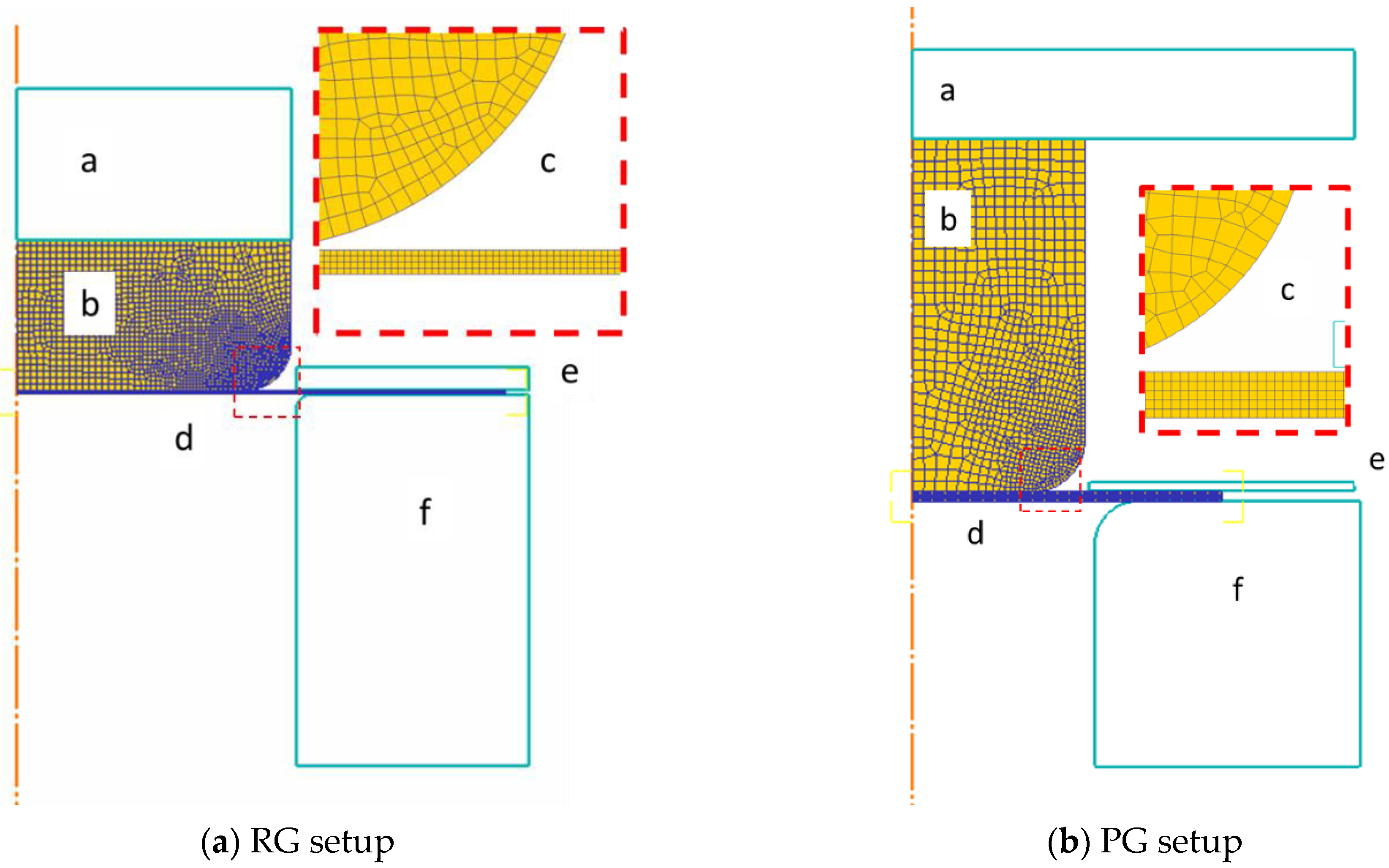
2.3. Numerical Analysis

Deform 2D software (SFTC, Columbus, OH, USA) was used for deep drawing simulations. Because of the cylindrical shape of tools and blanks, the process was simulated on an axis-symmetrical basis. The forming die and blank holder were simulated as rigid bodies in line with the limited objectives of the study; punches and blanks were simulated as plastic bodies. The use of 2D analysis and of rigid bodies for the forming die and blank holder resulted in reduced computation times, particularly in the case of RG. AISI 304 mechanical behaviour was taken from the Deform material database. Mechanical properties of CF Nylon were obtained from data in the literature [21,22]. Screw housing was not simulated because of its required location in the tool center. Preliminary tests showed that this did not affect results, so the tools were designed fully. A constant speed of 10 mm/s was set for the punch. For RG and RP test simulations, loads of 18 kN and 1 kN, respectively, were assigned to the blank holder. A tetrahedral mesh was used for both blanks and punches; blanks were modelled with regular quadric mesh with an element size of 0.2 mm, while punches were modelled with adaptative mesh with a shorter element length of 0.4 mm in the region of the fillet radius. To simulate contact between punch and blank, a shear function was set. Drawing on previous studies, and taking lubrification into consideration, a value of 0.1 was adopted [23,24]. A time discretization value of 0.1 was set for both RG and PG. All nodes in contact between the punch and press were locked to simulate mechanical assembly, and temperature was kept constant at 20 °C. Figure 3 shows the simulation setup for both processes.
At the end of the simulation analysis, the following results were evaluated:
-
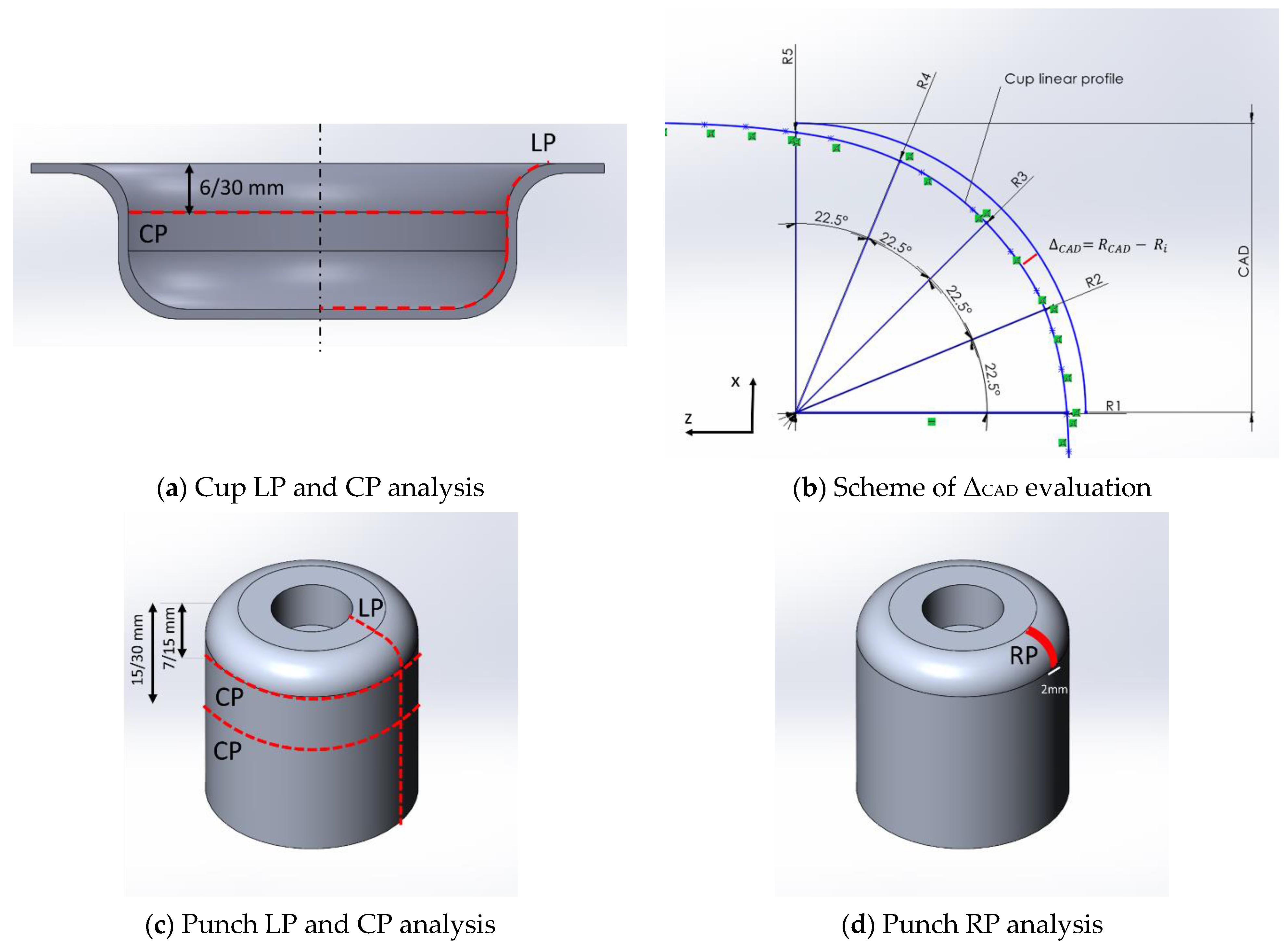
Comparison of cup LP profiles (experimental, simulation, CAD);
-
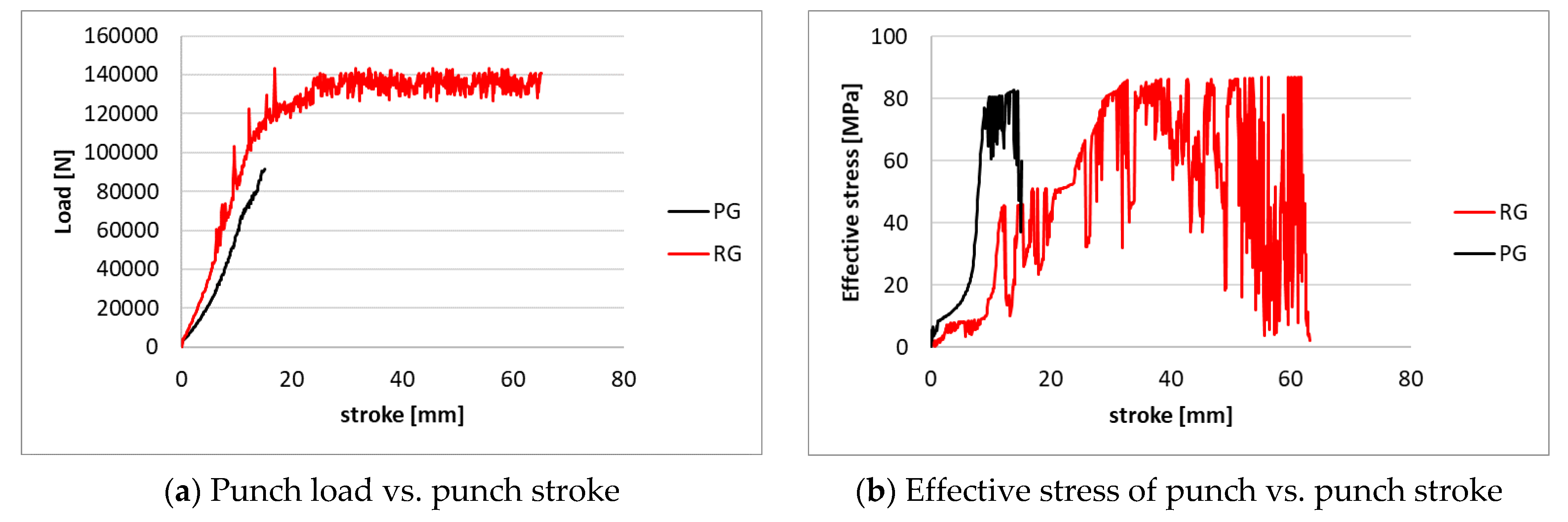
Punch load as a function of the stroke;
-
Punch effective stress as a function of the stroke evaluated on a point in the middle of the fillet radius.
-
Punch radial displacement.

3. Results

In this section, the main results are presented for cup analysis, punch analysis, and FEM results. An overall assessment of the deep drawing process can first be given, as follows: both punches were able to deform stainless blanks, and all cups were correctly produced without defects and without damaging plastic punches. Figure 4 shows examples of cups produced and related punches for both RG and PG.

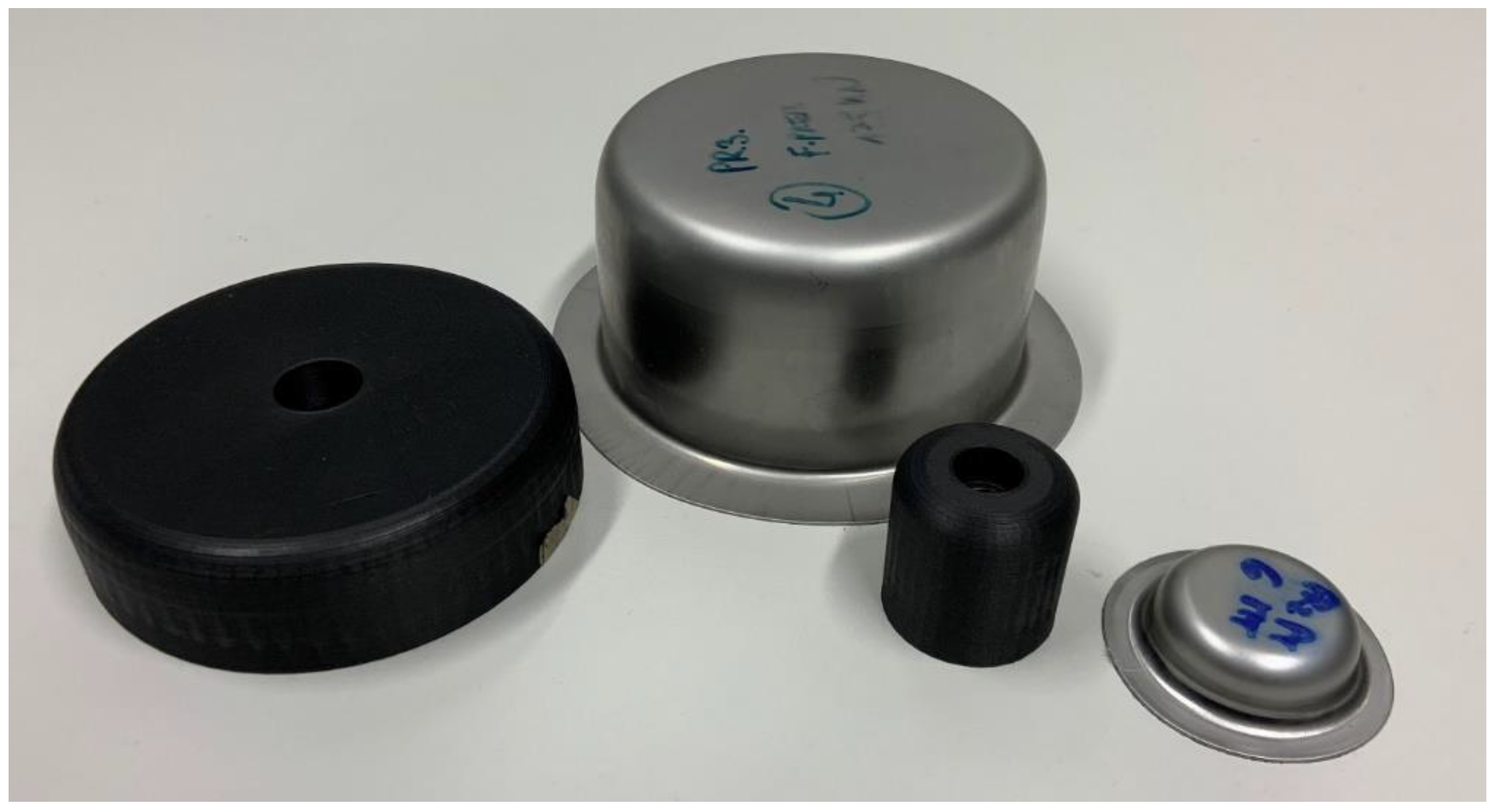
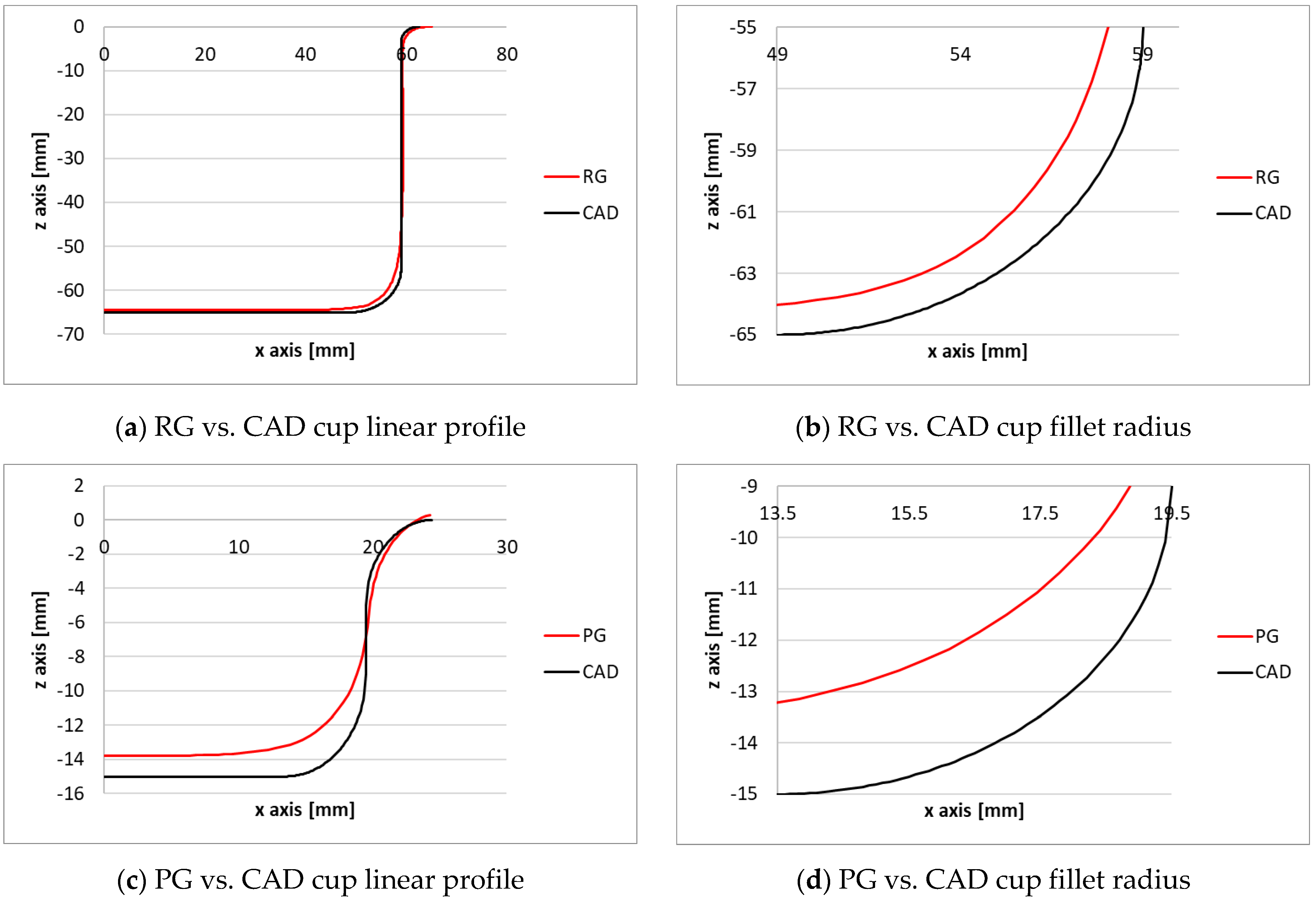
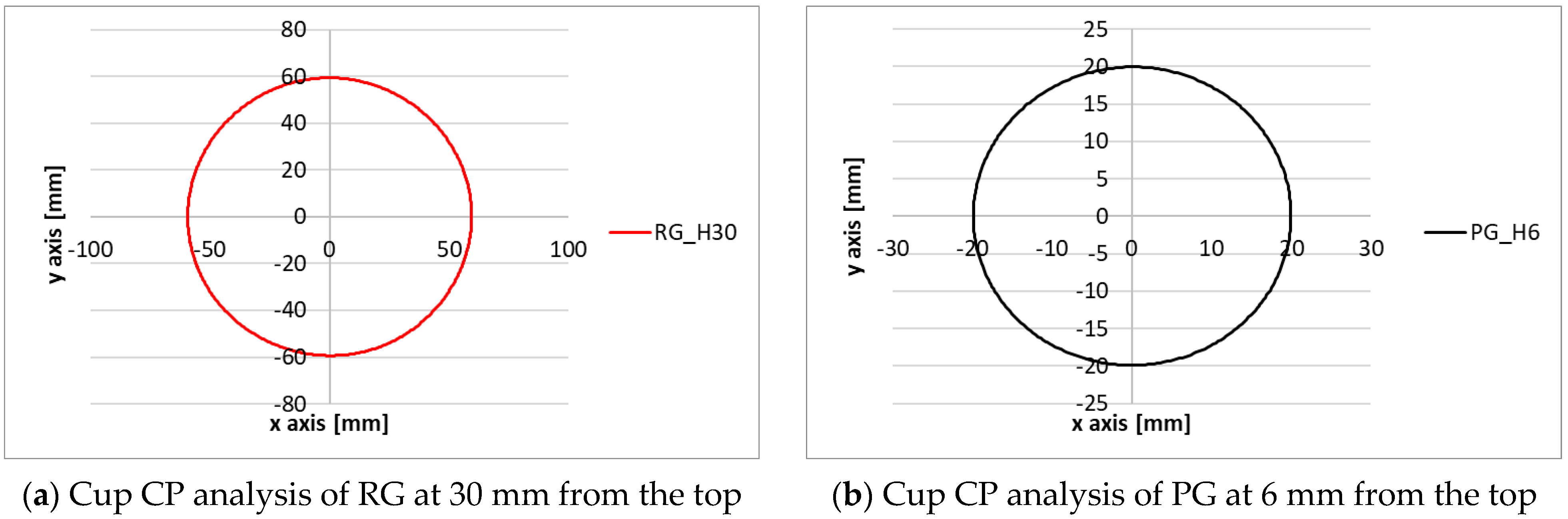
3.1. Experimental Cups Analysis

Figure 5 and Table 3 present qualitative and quantitative results of LP analysis.
Comparing the above results, it is clear that RG is more accurate than PG. Figure 5a shows how the RG geometry profile fits that of CAD. Figure 5b shows the main difference between the two, with respect to the fillet radius, where a difference of 1.09 mm was recorded. However, considering the 10 mm value of the ideal fillet radius, this is equivalent to a percentage deviation of 89%. In terms of drawing depth, the results shown in Table 3 reveal that RG produced cups with a drawing depth which was 99% of the expected value. In the PG test, the percentage deviations from the ideal fillet radius of 6 mm, and from the expected drawing depth of 15 mm, were 75% and 92%, respectively. It can therefore be asserted that the linear profile obtained with RG is more accurate than that obtained with PG.
CP analysis confirmed the LP results. The cups were produced with an average radius Rmed that diverged from the punches’ radius by just hundreds of microns, and with near-negligible standard deviation, as Figure 6 illustrates visually, and Table 4 describes quantitatively. Table 4 also shows that absolute values of roundness tolerances were higher in RG but were lower in percentage terms when related to the Rmed (0.53%).

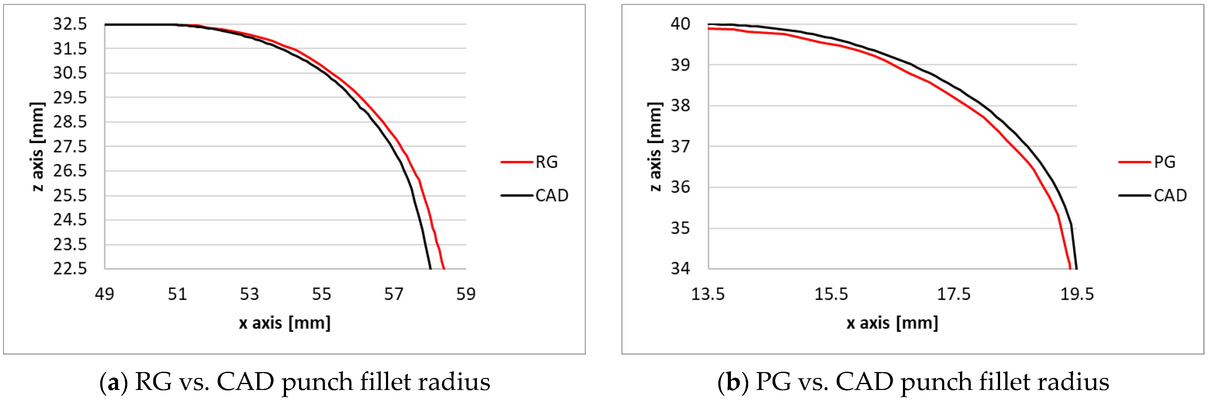
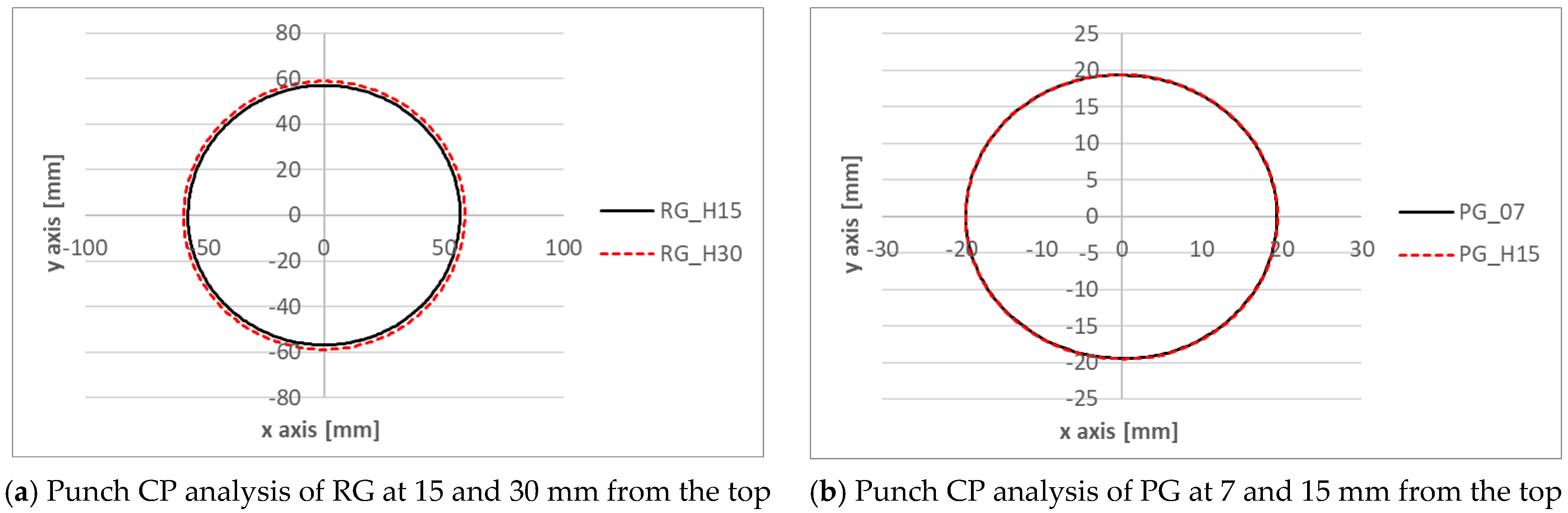
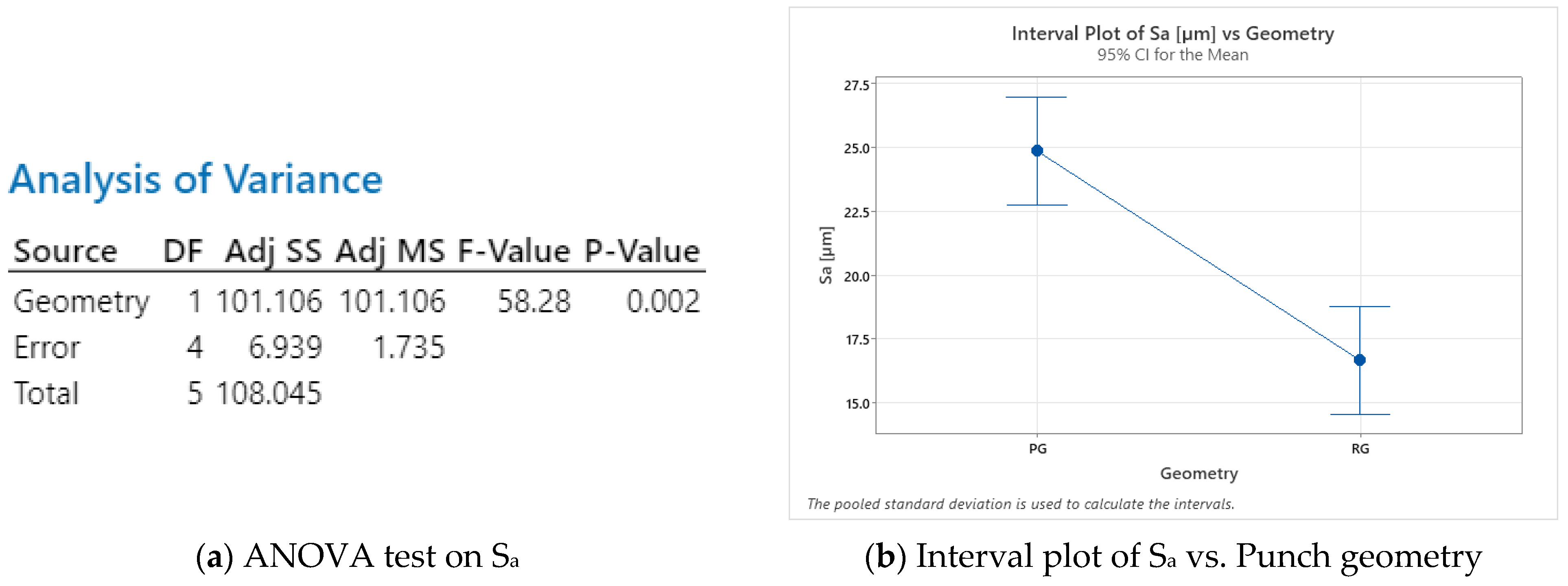
3.2. Experimental Punch Analysis

In this section, results of the measurements taken from punches after the deep drawing process are presented. The LP analysis shows how punches withstood the drawing process without significant permanent deformation; this is illustrated in Figure 7, in which the RG and PG punch fillet radii are compared with those of CAD. Table 5 presents the punch heights measured at the end of cup deformation. The analysis demonstrates that neither punch suffered permanent deformation.
The CP analysis highlighted the behaviour of punches, as follows: the two circumferences obtained at different distances from the punch top (Figure 8) are perfectly overlapped for PG; in RG the circumference acquired at 15 mm (the black line in Figure 8a) is slightly inferior to the circumference acquired at 30 mm (the red dotted line). However, an analysis of the roundness tolerances shown in Table 6 and the rt percentage on radii revealed that all values of the latter were below 1.5%, with a minimum value of 0.4% in the case of RG_H30.
The results of the roughness profile (RP) analysis are presented in Figure 9 and Figure 10. A qualitative and comparative observation of Figure 9 shows that RG has a smoother morphology than PG. To confirm this finding, Figure 10a presents the results of an analysis of variance (ANOVA) test of the average surface roughness Sa. These results (p-value < 0.05) confirm that the choice of punch geometry is significant. In addition, the interval plot depicted in Figure 10b shows that the fillet radius of RG has a lower Sa value (16.6 µm).

3.3. FEM Results

In this section, FEM results are used to plot values for variables that were not experimentally acquired, such as punch load, stresses and radial displacement. The accuracy of the test simulation is first confirmed in Figure 11, which shows a comparison of experimental, FEM and CAD cup linear profiles. All graphs are focused on cup fillet radius values within the higher deviation zone.
The FEM curves for the two punches lie between those of the CAD and experimental; this indicates a good ability to simulate the deep drawing process. After validation, simulations were used to highlight the behaviour of punches during the deep drawing process. Figure 12a plots the punch load as a function of the stroke. It can be seen that both RG and PG loads exhibit increasing trends with similar slopes. At a 15 mm stroke, PG attains a maximum load of 91 kN; however, RG values increase further until a maximum value of 136 kN is attained, which then remains constant. Contrarily, the plots of effective stress in Figure 12b show trends characterized by different slopes (higher in PG, lower in RG) in which both simulations nonetheless attain a similar maximum value of around 80 MPa. The noise phenomenon visible in the RG plot is due to a loss of contact between the cup and the selected node during the simulation process.
Finally, a comparison of the radial displacements undergone by the punches due to the compression loads is shown in Figure 13. Simulation results show a significant difference between RG and PG: the RG exhibited a displacement in a range of hundredths of a millimeters, with a maximum value equal to 0.07 mm; however, PG exhibited a maximum displacement of 0.33 mm.

4. Discussion

From a review of all the results, it can be concluded that process scalability is not only feasible but also offers potential benefits in terms of cup accuracy and punch deformation. The following findings are especially worthy of note:
Cup analysis identified a loss of accuracy on the fillet radius for both geometries (Figure 5); this finding is in line with the results of similar studies [16,18,20]. The highest loss of accuracy previously reported was around 0.8 mm [20] and this is consistent with the results shown in Table 3 above. However, it should be recalled that the results in this study were obtained using different punch materials (PLA, PA), and with different geometries from those used in previous studies, PG excepted. Nevertheless, the experimental results in Table 3 and Table 4 confirm that the use of RG resulted in cups with more precise geometry in terms of fillet radius (lowest ΔCAD) and circularity (lowest % rt/Rmed).
Punch analysis revealed similar results for RG and PG in terms of punch height, profile and circularity. This means that no worsening mechanism occurs when tool dimensions increase. The only significant difference in this regard was the 35% decrease in average surface roughness recorded in Figure 10; however, this effect was due to the different fillet radii, at least in part.
Comparing the results of cup and punch analysis, it can be seen that the loss of accuracy in cups was proportionately higher than the permanent deformation of punches. For example, the measured drawing height of PG cups was 13.8 mm, while the ideal height was 15 mm (Table 3). For punches, the corresponding measured and ideal heights were 39.9 mm and 40 mm, respectively. This suggests that punches experienced both elastic and plastic (permanent) deformation during the deep drawing process.
FEM analysis indicated that strain effective loads were similar, while maximum load increased by 50% when the process was scaled up (Figure 12). In addition, radial displacement was lower in RG by an order of magnitude, compared with PG (Figure 13).
These findings demonstrate that similar levels of punch compression during the deep drawing process lead to similar levels of equivalent stress; this stress therefore decreases when tool geometries increase. A reduction in deformation leads to an improvement in cup quality. However, to obtain tests with the same drawing ratio, punch and blank diameter were tripled with respect to prototype geometries, while blank thickness was reduced from 1 to 0.7 mm. These conditions certainly affected process performance, as well as the reduction in loads, stresses and related punch deformations. However, the industrial considerations of the study meant that there was no sense in using blanks of 3 mm thickness because the objective was to produce parts as thin as possible for material-saving purposes. Because production of the prototype geometry is easier, cheaper, and less time-consuming, this industrial-level test could be resized for future laboratory tests by reducing punch and blank diameters but maintaining blank thickness.

5. Conclusions

In this work, a comparison between punches designed for prototype testing and punches designed for industrial application with dimensions three times greater was carried out. Results were obtained for the quality of cups produced and also for the permanent deformation of punches. In addition, an FEM simulation was run to investigate physical parameters such as loads and stresses. The findings described above demonstrate that an increase in punch and blank diameter leads to a more precise production of cups and to a lower deformation of punches. These results confirm the potential of additive manufacturing for industrial applications, so long as geometry is kept simple, as in this study. Indeed, it may be especially convenient, compared to traditional punch production processes, when production batches are small-sized, delivery time is short, and there is a need to produce punches quickly. Research is already under way to further assess the performance of industrial punches for small- and medium-sized batch production.

Funding

This research received no external funding.

Institutional Review Board Statement

Not applicable.

Informed Consent Statement

Not applicable.

Data Availability Statement

Data available on request due to privacy restrictions.

Acknowledgments

The authors are grateful to R. Pinti of Pinti Inox S.P.a.–Sarezzo (Brescia) for the experimental campaign and the CMM analysis.

Conflicts of Interest

The authors declare no conflict of interest.

References

  1. Pansare, R.; Yadav, G.; Nagare, M.R.; Jani, S. Mapping the competencies of reconfigurable manufacturing system with the requirements of industry 4.0. J. Remanuf. 2022, 12, 385–409. [Google Scholar] [CrossRef]
  2. Malaga, A.; Vinodh, S. Technology Selection for Additive Manufacturing in Industry 4.0 Scenario Using Hybrid MCDM Approach. In Industry 4.0 and Advanced Manufacturing; Springer: Singapore, 2023; pp. 207–217. [Google Scholar] [CrossRef]
  3. Levy, G.N.; Schindel, R.; Kruth, J.P. Rapid manufacturing and rapid tooling with layer manufacturing (LM) technologies, state of the art and future perspectives. CIRP Ann.-Manuf. Technol. 2003, 52, 589–609. [Google Scholar] [CrossRef]
  4. Sachs, E.; Cima, M.; Williams, P.; Brancazio, D.; Cornie, J. Three Dimensional Printing: Rapid Tooling and Prototypes Directly from a CAD Model. J. Eng. Ind. 1992, 114, 481–488. [Google Scholar] [CrossRef]
  5. Rosochowski, A.; Matuszak, A. Rapid tooling: The state of the art. J. Mater. Process. Technol. 2000, 106, 191–198. [Google Scholar] [CrossRef]
  6. Huzaim, N.H.M.; Rahim, S.Z.A.; Musa, L.; Abdellah, A.E.-H.; Abdullah, M.M.A.B.; Rennie, A.; Rahman, R.; Garus, S.; Błoch, K.; Sandu, A.V.; et al. Potential of Rapid Tooling in Rapid Heat Cycle Molding: A Review. Materials 2022, 15, 3725. [Google Scholar] [CrossRef]
  7. Wang, W.; Conley, J.G.; Stoll, H.W. Rapid tooling for sand casting using laminated object manufacturing process. Rapid Prototyp. J. 1999, 5, 134–140. [Google Scholar] [CrossRef]
  8. Giorleo, L.; Bonaventi, M. Casting of complex structures in aluminum using gypsum molds produced via binder jetting. Rapid Prototyp. J. 2021, 27, 13–23. [Google Scholar] [CrossRef]
  9. Kuo, C.-C.; Lin, B.-H.; Luo, Z.-T. A new hybrid process combining rapid tooling and machining to manufacture an injection mold with micro features. Int. J. Adv. Manuf. Technol. 2022, 119, 6349–6360. [Google Scholar] [CrossRef]
  10. Giorleo, L.; Stampone, B.; Trotta, G. Micro injection moulding process with high-temperature resistance resin insert produced with material jetting technology: Effect of part orientation. Additive Manuf. 2022, 56, 102947. [Google Scholar] [CrossRef]
  11. Wen, T.; Liu, L.; Wang, X.; Zheng, Y.; Yang, F.; Zhou, Y. Zinc-based alloy rapid tooling for sheet metal forming reinforced by SLM steel inlays. Int. J. Adv. Manuf. Technol. 2022, 122, 761–771. [Google Scholar] [CrossRef]
  12. Giorleo, L.; Ceretti, E. Deep drawing punches produced using fused filament fabrication technology: Performance evaluation. J. Manuf. Process. 2022, 84, 1–9. [Google Scholar] [CrossRef]
  13. Liewald, M.; Souza, J.H.C. New developments on the use of polymeric materials in sheet metal forming. Prod. Eng. 2008, 2, 63–72. [Google Scholar] [CrossRef]
  14. Kuo, C.-C.; Li, M.-R. Development of sheet metal forming dies with excellent mechanical properties using additive manufacturing and rapid tooling technologies. Int. J. Adv. Manuf. Technol. 2017, 90, 21–25. [Google Scholar] [CrossRef]
  15. Schuh, G.; Bergweiler, G.; Bickendorf, P.; Fiedler, F.; Colag, C. Sheet metal forming using additively manufactured polymer tools. Procedia CIRP 2020, 93, 20–25. [Google Scholar] [CrossRef]
  16. Frohn-Sörensen, P.; Geueke, M.; Tuli, T.B.; Kuhnhen, C.; Manns, M.; Engel, B. 3D printed prototyping tools for flexible sheet metal drawing. Int. J. Adv. Manuf. Technol. 2021, 115, 2623–2637. [Google Scholar] [CrossRef]
  17. Geueke, M.; Frohn-Sörensen, P.; Reuter, J.; Padavu, N.; Reinicke, T.; Engel, B. Structural optimization of additively manufactured polymer tools for flexible sheet metal forming. Procedia CIRP 2021, 104, 1345–1350. [Google Scholar] [CrossRef]
  18. Bergweiler, G.; Fiedler, F.; Shaukat, A.; Löffler, B. Experimental investigation of dimensional precision of deep drawn cups using direct polymer additive tooling. J. Manuf. Mater. Process. 2021, 5, 3. [Google Scholar] [CrossRef]
  19. de Souza, J.H.C.; Liewald, M. Analysis of the tribological behaviour of polymer composite tool materials for sheet metal forming. Wear 2010, 268, 241–248. [Google Scholar] [CrossRef]
  20. Frohn-Sörensen, P.; Geueke, M.; Engel, B.; Löffler, B.; Bickendorf, P.; Asimi, A.; Bergweiler, G.; Schuh, G. Design for 3D Printed Tools: Mechanical Material Properties for Direct Polymer Additive Tooling. Polymers 2022, 14, 1694. [Google Scholar] [CrossRef]
  21. Pyl, L.; Kalteremidou, K.-A.; Van Hemelrijck, D. Exploration of specimen geometry and tab configuration for tensile testing exploiting the potential of 3D printing freeform shape continuous carbon fibre-reinforced nylon matrix composites. Polym. Test. 2018, 71, 318–328. [Google Scholar] [CrossRef]
  22. Papa, I.; Silvestri, A.T.; Ricciardi, M.R.; Lopresto, V.; Squillace, A. Effect of fibre orientation on novel continuous 3d-printed fibre-reinforced composites. Polymers 2021, 13, 2524. [Google Scholar] [CrossRef] [PubMed]
  23. Unal, H.; Mimaroglu, A. Friction and wear performance of polyamide 6 and graphite and wax polyamide 6 composites under dry sliding conditions. Wear 2012, 289, 132–137. [Google Scholar] [CrossRef]
  24. Meng, H.; Sui, G.X.; Xie, G.Y.; Yang, R. Friction and wear behavior of carbon nanotubes reinforced polyamide 6 composites under dry sliding and water lubricated condition. Compos. Sci. Technol. 2009, 69, 606–611. [Google Scholar] [CrossRef]
Figure 1. Drafting of (a) real RG and (b) prototype PG geometries designed for the experimental tests.
Applsci 12 12716 g001
Figure 2. Methods adopted to analyze the experimental results.
Applsci 12 12716 g002
Figure 3. Setup of elements modelled for deep drawing simulations: (a) press; (b) punch; (c) punch with higher mesh magnification on the fillet radii; (d) blank; (e) blankholder; (f) matrix.
Applsci 12 12716 g003
Figure 4. Cups produced with RG (left) and PG (right) and related punches.
Applsci 12 12716 g004
Figure 5. Main results of cup LP analysis.
Applsci 12 12716 g005
Figure 6. Main results of cup CP analysis.
Applsci 12 12716 g006
Figure 7. Main results of cup LP analysis.
Applsci 12 12716 g007
Figure 8. Main results of punch CP analysis.
Applsci 12 12716 g008
Figure 9. Fillet radius morphology of (a) real and (b) prototype geometry with (c) scale bar.
Applsci 12 12716 g009
Figure 10. Main results of punch RP analysis.
Applsci 12 12716 g010
Figure 11. Comparison of cup LP between experimental (red), simulation (black dashed) and CAD (black).
Applsci 12 12716 g011
Figure 12. Load and stress punch analysis during deep drawing process.
Applsci 12 12716 g012
Figure 13. Radial displacement of simulated punches at the end of the deep drawing process.
Applsci 12 12716 g013
Table 1. Main blank and tool dimensions and process parameters.
Prototype Geometry (PG)Real Geometry (RG)
Blank materialAISI 304AISI 304
Blank diameter [mm]70210
Blank thickness [mm]10.7
Drawing ratio1:81:8
Drawing depth [mm]1565
Punch material [mm]CF_NylonCF_Nylon
Punch diameter [mm]39118
Punch fillet radius [mm]610
Punch speed [mm/s]1010
Matrix material45 NiCrMo 1645 NiCrMo 16
Matrix internal diameter [mm]41.2120.16
Matrix fillet radius [mm]53.5
Clearance distance [mm]0.10.38
Blankholder load [kN]118.5
Table 2. Mechanical properties of punches, forming dies and blanks.
CF Nylon45 NiCrMo 16AISI 304
Tensile modulus [GPa]2.4284193
Tensile stress at yield (Mpa)37696190
Tensile stress at break (Mpa)40950500–700
Tensile strain at break (%)251140
Density (g/cm3)1.27.848
Table 3. Main results of cup LP analysis.
RGPG
ΔCAD [mm]1.09 ± 0.161.53 ± 0.54
% ΔCAD89%75%
Drawing depth [mm]64.513.8
% of drawing depth99%92%
Table 4. Main results of cup CP analysis.
RG_H30PG_H6
Rmed [mm]59.3219.93
σ [mm]0.080.04
Rmax [mm]59.4320.01
Rmin [mm]59.1219.88
rt [mm]0.3140.133
% rt/Rmed0.53%0.68%
Table 5. Punch height measured after the deep drawing process.
RGPG
Punch height [mm]32.4839.94
Table 6. Main results of punch CP analysis.
RG_H15RG_H30PG_07PG_H15
Rmed [mm]56.9 ± 0.158.8 ± 0.0519.5 ± 0.0819.5 ± 0.07
rt [mm]0.3840.2360.2740.270
% rt/Rmed0.65%0.40%1.40%1.38%
Publisher’s Note: MDPI stays neutral with regard to jurisdictional claims in published maps and institutional affiliations.

