Article

Implementation and Evaluation of Dynamic Task Allocation for Human–Robot Collaboration in Assembly

1
BIBA—Bremer Institut für Produktion und Logistik GmbH, University of Bremen, Hochschulring 20, 28359 Bremen, Germany
2
Faculty of Production Engineering, University of Bremen, Badgasteiner Straße 1, 28359 Bremen, Germany
*
Author to whom correspondence should be addressed.
Appl. Sci. 2022, 12(24), 12645; https://doi.org/10.3390/app122412645
Submission received: 17 November 2022 / Revised: 1 December 2022 / Accepted: 7 December 2022 / Published: 9 December 2022
(This article belongs to the Special Issue New Insights into Collaborative Robotics)

Abstract

:
Human–robot collaboration is becoming increasingly important in industrial assembly. In view of high cost pressure, resulting productivity requirements, and the trend towards human-centered automation in the context of Industry 5.0, a reasonable allocation of individual assembly tasks to humans or robots is of central importance. Therefore, this article presents a new approach for dynamic task allocation, its integration into an intuitive block-based process planning framework, and its evaluation in comparison to both manual assembly and static task allocation. For evaluation, a systematic methodology for comprehensive assessment of task allocation approaches is developed, followed by a corresponding user study. The results of the study show for the dynamic task allocation on the one hand a higher fluency in the human–robot collaboration with good adaptation to process delays, and on the other hand a reduction in the cycle time for assembly processes with sufficiently high degrees of parallelism. Based on the study results, we draw conclusions regarding assembly scenarios in which manual assembly or collaborative assembly with static or dynamic task allocation is most appropriate. Finally, we discuss the implications for process planning when using the proposed task allocation framework.

1. Introduction

Future manufacturing environments are characterized by workplaces in which human workers and robots work closely together [1]. The industrial assembly has a key impact on productivity and profitability of companies [2] and is to date still largely operated fully manually [3,4]. In view of increasing flexibility requirements due to individualized products, dynamically changing market demands, and shorter product life cycles [5], appropriate solutions to ensure companies’ efficiency and profitability must be implemented [6]. When effectively combining the strengths of humans and robots, productivity for small to medium batch sizes can be improved compared to purely manual assembly [7], while maintaining a higher degree of flexibility compared to fully automated systems [8]. Consequently, industrial assembly represents one of the main fields for the transformation towards hybrid workplaces in human–robot collaboration (HRC) [9,10].
From a human-centric perspective, which belongs to the key concepts for the evolution towards Industry 5.0 [11], particularly Operator 5.0 [12], employees working in such hybrid assembly workplaces should be supported in a meaningful way, with the aim of reducing monotonous, repetitive, or ergonomically unfavorable tasks to a minimum, and relieving the employees’ cognitive stress [13]. Therefore, the combination of information-based assembly assistance systems, which are already widely used in industrial manual assembly, with collaborative robots as a physical support system offers a promising solution approach for the design of hybrid assembly workplaces [14,15,16].
The aforementioned envisioned potentials of collaborative robots are reflected in a strongly growing market volume for collaborative robots [17]. The dominant industrial application is the field of assembly, which accounts for a share of more than 70% of collaborative robot applications [18] and is also the most studied area in HRC research [13]. The main tasks of collaborative robots are gripping, mounting or joining, quality control, pick and place, packing and palletizing, and machine loading [18,19]. Driving sectors are especially the automotive and electronics industries [13,18,20]. However, smaller companies in particular rarely use collaborative robots to date [21]. Moreover, in most industrial applications of collaborative robots, human workers and robots work in separate workspaces and do not collaborate closely together yet [18,22,23]. Here, two major topic areas were identified as challenges explaining this lack of application in which humans and robots share the same collaborative workspace, namely (1) safety aspects and (2) planning aspects [8,24].
This article addresses the planning challenge of task allocation, i.e., an effective division of labor between humans and robots. The allocation of tasks to humans or robots can be performed either statically, i.e., prior to task execution, or dynamically, i.e., in response to changes during the task execution [25,26]. In the literature, various methods for both static and dynamic task allocation have been proposed (see Section 1.2). However, on the one hand, apart from validating the principal functionality of the respective methods or evaluating them in simulation studies, no comprehensive evaluation in an experimental test setup has yet been conducted that systematically examines and empirically assesses the advantages and disadvantages of both approaches to task allocation. On the other hand, related approaches do not focus on an intuitive and integrated creation of the HRC assembly processes.
To overcome this research gap, this work presents on the one hand the development of an approach for dynamic task allocation as well as its implementation into a robot no-code programming framework, including the visualization of worker instructions and the assembly progress. On the other hand, it focuses on a systematic evaluation of the dynamic task allocation approach in comparison with static task allocation in a laboratory user study. The results of this article provide new insights about the most suitable task allocation mode for human–robot collaboration depending on the quality of the initial static planning, on the duration of possible process interruptions, and on the flexibility (in terms of parallelism and length) of the assembly process.
The remainder of this article is structured as follows: Section 1.1 and Section 1.2 provide an overview on HRC in assembly and related task allocation approaches for HRC, including their evaluation results. Based on this, a summary on the scope and contribution of the article is given in Section 1.3. Section 2 first describes the proposed methodology for dynamic task allocation including its integration into the no-code programming framework. Then, the user study design including the experimental setup and procedure of the study as well as the applied metrics and the evaluation procedure are presented. The results of the study are provided in Section 3 and are subsequently discussed in Section 4. Finally, Section 5 concludes this article by summarizing the main findings and provides an outlook on future research directions.

1.1. Human–Robot Collaboration

1.1.1. Challenges for Introducing Collaborative Robots

The potentials and expectations associated with HRC are an increase in quality, efficiency, flexibility, and productivity while improving ergonomic working conditions and reducing the repetitive workload [18,26,27,28]. However, several studies [8,22,24,29,30] also examined the challenges that still hinder the introduction of collaborative robots. An overview of the identified major challenges is collected in Table 1 and classified into the categories of safety, planning, and technology (cf. [24]). Similar aspects were also reported in the vice versa study on success factors for the introduction of industrial HRC [31]. This article focuses on the identified challenge of appropriate task allocation (see Table 1).

1.1.2. Classification of Cooperation Levels between Humans and Robots

Figure 1 shows a classification of cooperation levels between humans and robots into five types—cell, coexistence, synchronized (also sequential cooperation [32]), cooperation, and collaboration—depending on the workspace, the task, and the required safety mechanisms [18,33]. Cellular operation represents the classical safety fence operation of industrial robots, which is used in fully automated processes, while the other types of collaboration are typically realized with collaborative robot systems.
A requirement for the implementation of a dynamic task allocation is the existence of a shared workspace, as both the human and the robot must be able to substitute their counterpart and perform the appropriate assembly work when the other is not available. Thus, due to the shared workspace, dynamic task allocation is feasible in the cooperation levels of synchronization, cooperation, and collaboration.

1.2. Task Allocation for Human–Robot Collaboration in Assembly

To address the challenge of task allocation, several methods were proposed, which can be classified into static or dynamic task allocation approaches [25,26]. Static task allocation mainly considers the planning phase (“offline”), dealing with the creation of a fixed task schedule prior to execution. For this, both planning methods and optimization algorithms have been proposed. Planning methods are either carried out manually, e.g., [26,27], or in conjunction with a planning assistance system, e.g., [35]. In such methods, the potentials of both resources are usually assessed first and then a process schedule is created using a task allocation logic based on the assessment. Optimization approaches automatically generate different allocation alternatives and select the one that best satisfies a cost function, e.g., [36,37,38]. In contrast, dynamic task allocation approaches, e.g., [39,40], consider the assembly execution phase (“online”) and focus on the (re-)allocation of tasks in the case of deviations from the initial assembly planning.
Table A1 in Appendix A provides an overview of related work on task allocation, including a short description regarding the type of the proposed approach. Further, details on the evaluation scenario, the evaluation approach, and the main results of the evaluation are presented. The vast majority of task allocation approaches in the related work only validate the general functionality of the proposed approach. However, only a few articles [36,38,41] evaluate their approach by comparing the resulting task schedules or the metrics of the actual assembly process execution with those of manual assembly. Moreover, effects of real-time execution arising from the assembly execution by different, also untrained persons, or from delays due to unforeseen events, are rarely taken into account. Instead of carrying out a user study with users being not familiar with the system, the proposed approaches are often either solely tested in simulation or by the respective authors themselves.
For considering these effects, only two references [42,43] conducted user studies for evaluation of their proposed approaches (highlighted in light grey in Table A1). From those, the study in [42] evaluates the implications of different trust levels on human satisfaction and assembly performance. Reference [43] proposes a dynamic task allocation system that aims at minimizing human fatigue and compares their approach with a static task plan in a user study.

1.3. Scope and Contributions of the Article

The dynamic task allocation system presented in this work differs from the approach in [43] by focusing on the dynamic reduction in cycle times, even in the case of unforeseen delays on the one hand and by integrating the approach into a block-based programming framework on the other. With the latter, we aim to address—in addition to the core subject matter of task allocation—the reported challenge of intuitive programming (cf. Table 1) and aim to enable easy transferability to different application scenarios. Thus far only very few approaches to task allocation utilize block-based or visual programming for task allocation, but hard-code the program for the specific application instead. We only identified one approach [30] that utilizes a BPMN-based drag-and-drop programming interface for defining tasks as either human or robot. However, these tasks are only assigned statically without a possibility for dynamic adaptation.
The dynamic task allocation system proposed in this article is therefore the first that integrates intuitive block-based programming with dynamic task allocation. The block-based programming facilitates planning and enables transferability to different use cases as well as different robotic systems.
The dynamic task allocation methodology further differs from the related work approaches that mostly require an initial static process planning prior to execution, which is then adapted during execution in the case of plan deviations by flipping the task assignment. As such deviations occur frequently in high-mix, low-volume assembly, resulting in a high variability of the time spent on each task [44], we present a system that minimizes the initial planning effort by only requiring the task classification and the assembly priority chart as inputs to create a process flow. The process control and the task allocation are then performed automatically during task execution.
Within this article, we further intend to evaluate the effects of static and dynamic task allocation depending on planning quality, duration of delays, and the degree of process flexibility. For this, we propose an evaluation system and perform the evaluation in a comprehensive user study. By systematically investigating the dependencies on these aspects, we seek to derive a first recommendation regarding scenarios in which either static or dynamic task allocation is preferable.

2. Materials and Methods

The research work presented in this article is based on the Design Science Research (DSR) framework [45,46] and follows the DSR procedure model proposed in [46]. Figure 2 shows the contents of this article and links them to the phases of the DSR process. In addition, the methodological approach within the phases is briefly described and a reference to the individual sections of this article is given.
The following sections first shortly describe the software framework and the system architecture utilized for the implementation of the task allocation system (Section 2.1) to provide the overall context for understanding the system. Then, the designed planning procedure and the dynamic task allocation methodology as well as its integration into the software framework in terms of implementation details and user interface design are presented in Section 2.2. Finally, Section 2.3 presents details on the design of the evaluation study regarding the experimental setup, the implemented task allocation modes, the study procedure, the recorded parameters and metrics, as well as the data analysis.

2.1. Software Framework for Block-Based No-Code Programming

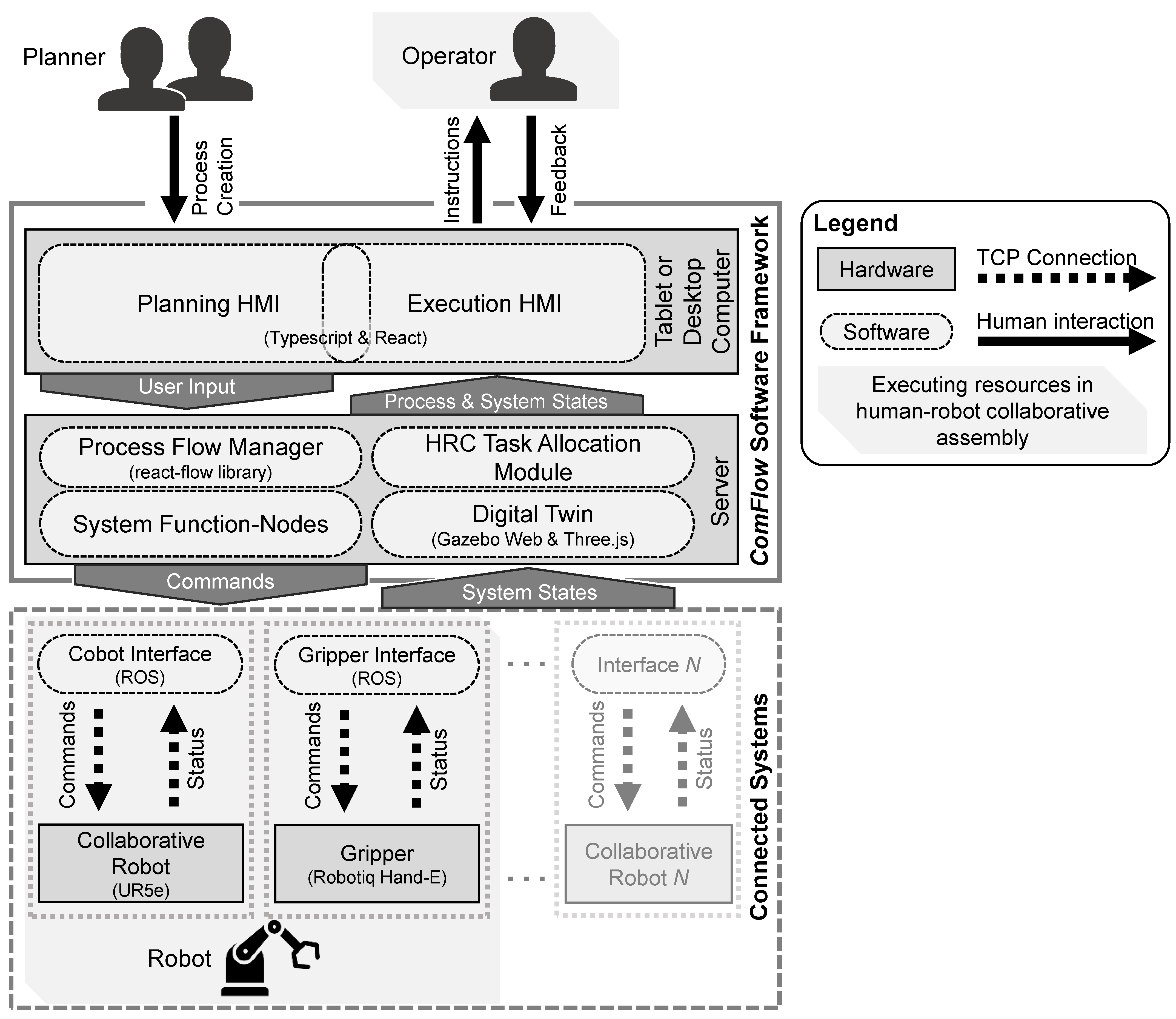
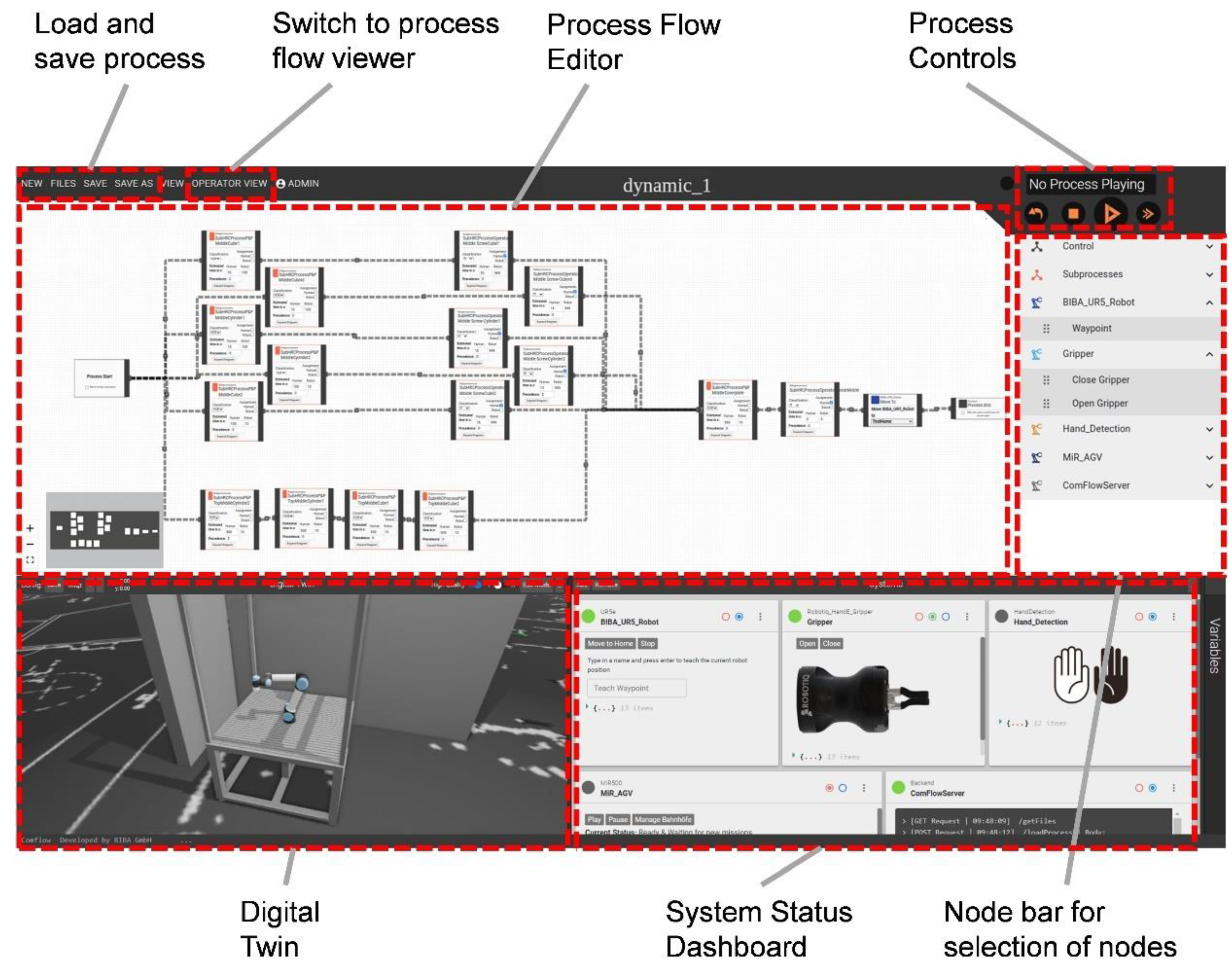
Based on the desire to ensure a broad usability of the envisaged approach for task distribution and an easy adaptation to different use cases or robotic systems, a visual no-code programming framework was chosen as a basis for the implementation of HRC task allocation. The framework ComFlow [47,48] satisfies these requirements by enabling an intuitive generation of process flows for various technical systems via a web-based user interface by means of system-specific functional blocks. Figure 3 shows the system architecture of the ComFlow software framework including the integrated module for task allocation proposed in this article. The framework consists of a server to which different technical systems can be connected, a process flow manager for creation and control of process flows, a digital twin for virtual testing of processes during the planning phase and real-time monitoring of systems during the execution phase, and the module for HRC task allocation, which is detailed in the following section. The process flow manager and the digital twin are both integrated into the web-based user interface, which can be accessed by different end-devices. The user interfaces comprise two views—a planning view (planning HMI) and an execution view (execution HMI)—as schematically illustrated in Figure 4.
For each technical system to be controlled, functional blocks are defined which map to control commands of the respective system, such as movement to waypoint or control of gripper. In addition, system-independent functional blocks can be created, which enable human interaction in terms of information provision and requests for confirmation on the one hand, or control the process flow, for example by means of and/or connections, pauses, or multi-output decision nodes. Using these functional nodes, the user can create process flows by drag-and-drop blocks and connect blocks to create the logical process sequence (see Section 2.2.3). The use of and nodes also allows easy synchronization between different systems, as these ensure that all connected preceding functional blocks have been completed.
Further details on the ComFlow software framework, including a research study validating the time-effectiveness and intuitive usability of the planning software, are provided in [47,48].

2.2. Dynamic Task Allocation Module

In the following, the proposed HRC task allocation module that enables the combination of flexible block-based programming with dynamic task allocation of assembly processes is explained. First, the indented planning process is described (Section 2.2.1), followed by an explanation of the proposed dynamic task allocation methodology (Section 2.2.2), and finally its implementation into the block-based software framework (Section 2.2.3).

2.2.1. Planning Procedure

This article primarily focuses on the real-world realization phase of the assembly planning process. Therefore, the following inputs are assumed to be given from assembly draft planning:
  • Assembly priority chart;
  • Task time estimation;
  • Task classification.
The assembly priority chart (or assembly precedence graph) is a typical planning document that is created along the phases of the assembly planning process [49], regardless of whether it is a manual, hybrid, or fully automated assembly process. The task time estimation can be carried out with the help of different time determination methods. Depending on brownfield or greenfield planning, time measurement, MTM for human execution times, and MTM-HRC [50] for estimation of robot execution times can be used. The task classification contains information about whether a task can in principle be performed by the human, by the robot, or by both. In the following, we denote tasks that can only be performed by the human or by the robot, respectively, as tasks with unambiguous task classification. In order to systematically assess the information about task classification, various methods have been proposed in the state of research, such as [26,35] (see also Section 1.2).
Given these input data, the process for realization and execution of the assembly process covered by the system proposed in this article is shown in Figure 4. First, the planning or commissioning personnel creates the individual tasks of the process. These tasks each include the separate definition of the human and robotic commands necessary to complete the task by the respective resource. For the human, this is typically a set of informational assembly instructions in the form of textual description and a visual illustration. A sequence of motion and gripping activities is typically defined for the robot, for which the corresponding waypoints for the robot need to be taught initially.
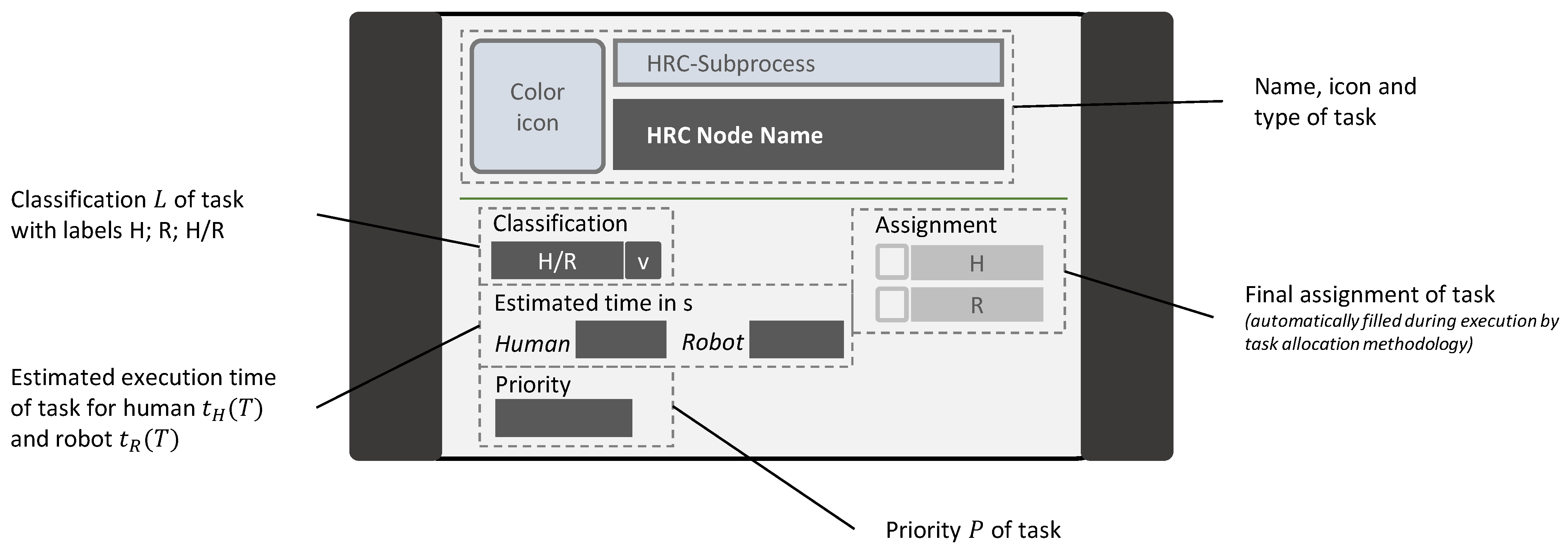
After the creation of all sub-processes, the overall assembly process is created. This is performed by linking the individual tasks, which are represented as functional blocks (HRC nodes, see Figure 5), according to the given assembly priority chart. Finally, the task classification and time estimation are defined for each HRC node.
Once the process has been created, it can immediately be tested in simulation using the digital twin and then be executed on the real human–robot assembly station, all within the same software framework.
During execution, the ComFlow process manager ensures the execution of the generated process flow according to the priority constraints and communicates with the dynamic task allocation module for the assignment of tasks to a human or robot. Depending on the assignment, the respective defined execution sequences are retrieved, and the commands are sent to the robot or the worker instruction system for execution by the respective resource. After finishing an executed task, the completion of the task is reported to the process manager based on the robot status or by active confirmation from the worker. Afterwards, the next tasks are assigned until the entire assembly process is completed.
A conceptual depiction of the corresponding user interfaces for the realization and execution phase are shown in the lower part of Figure 4; further details on the actual implementation are given in Section 2.2.3.

2.2.2. Methodology for Dynamic Task Allocation

The task allocation module of the presented system architecture (see Figure 3 and Figure 4) implements the methodology for distributing tasks between humans and robots during execution of a created process flow. The proposed methodology for dynamic task allocation is described in the following.
During the above explained process creation, the individual HRC nodes are created and interlinked, and the properties of these nodes are entered via input masks. As shown in Figure 5, these properties cover information about the task classification, the estimated execution time of the task for humans and robots, and the priority of the task. The latter serves as an additional decision criterion to determine a suitable prioritization with regard to the execution sequence of tasks.
As schematically illustrated in Figure 6, the created overall assembly process consists of a set of tasks T . During execution, the tasks are executed progressively according to the precedence relationships and the task allocation logic until the process is terminated with the end node. During this, the states of the tasks change as follows (cf. Figure 6):
  • Not executed—not yet available (remaining tasks; highlighted in gray);
  • Not executed—available (currently available tasks Tav; yellow);
  • In execution by robot (blue), or in execution by human (purple);
  • Completed (finished tasks; green).
Figure 6. Schematic representation of a process flow during process execution with different states of tasks and task clusters highlighted.
Applsci 12 12645 g006
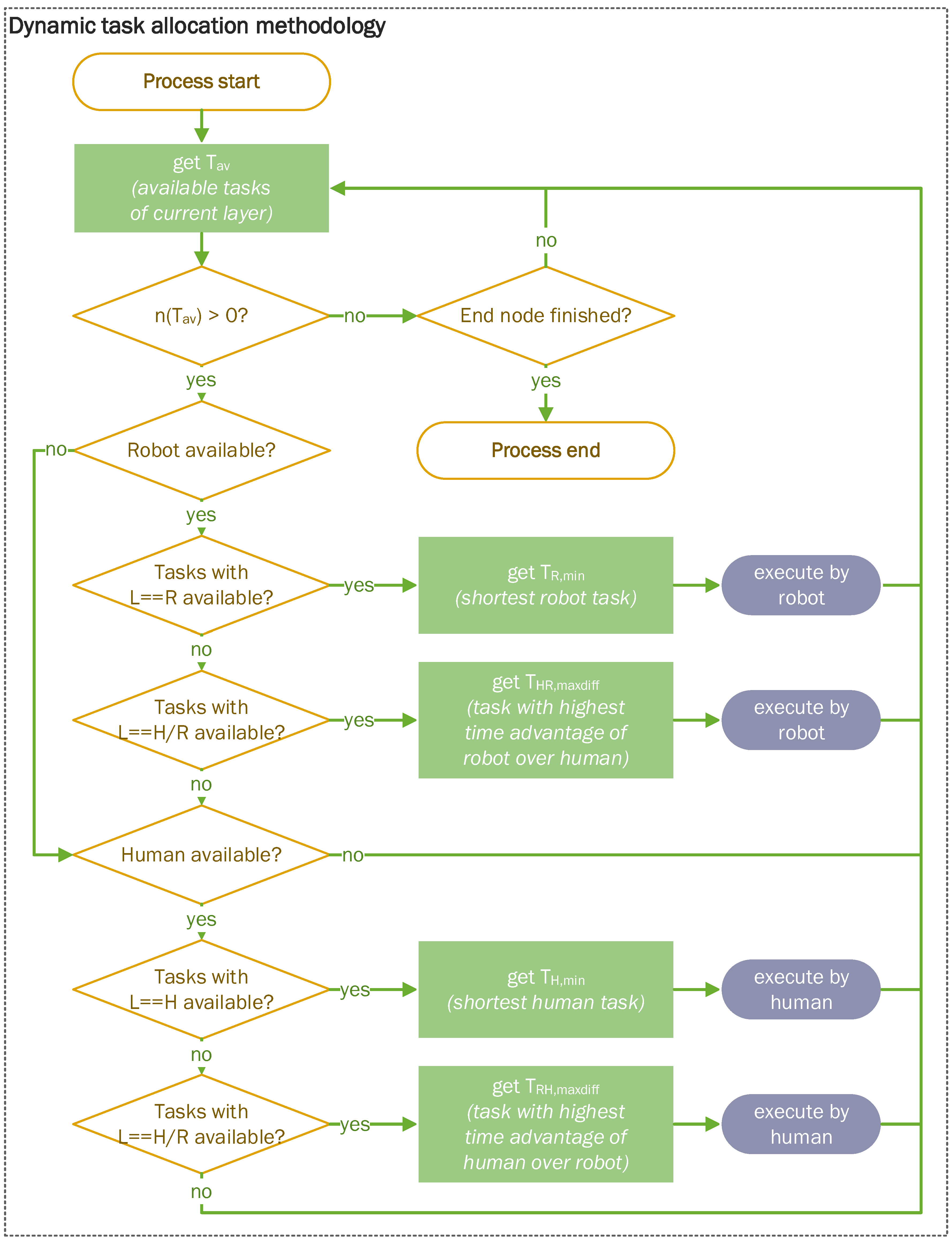
Figure 7 shows the flowchart of the proposed methodology for dynamic task allocation. A more detailed version of the flowchart is provided in Appendix D in Figure A2. The variables are denoted as follows:
T av Available tasks of current layer (see Figure 6, yellow);
T av i The i th task from available tasks T av of current layer;
n T Number of tasks  T ;
L Classification of task—available resource labels are H : human, R : robot, H / R : human or robot;
T av ,   L = X Available tasks with resource label  X (i.e.,  H , R , or H / R );
P T Priority of task;
T X , min Task with minimal execution time among tasks with label  X ;
T term , P Task with highest priority P min , i.e., minimum numeric value  P , among tasks fulfilling the condition term;
T XY , maxdiff Task with a maximum difference between the execution times of resources X and Y among tasks with label XY;
t X T Estimated execution time of resource X (H: human or R: robot) for task T.
The general idea of the dynamic task allocation methodology is to iteratively (either continuously or after finishing a task) request all currently available tasks T av and decide for these which task should be performed next by either the human or the robot. For this decision, the abovementioned properties of the HRC nodes are utilized. The decision for the assignment of tasks is conducted according to the following scheme:
  • The availability of the resources is checked.
  • For each available resource, the currently available task with an unambiguous, matching task classification and minimum execution time (see Equations (1) and (2) for calculation) is assigned.
  • If no more tasks with unambiguous task classification are currently available, tasks which are eligible for both the human and robot are considered, and the task in which the particular resource has the highest advantage in execution time over the other (see Equations (3) and (4) for calculation) is assigned to the respective available resource.
As referenced above, the following formulas are used to determine the variables T R , min , T H , min , T HR , maxdiff , and T RH , maxdiff used in the flowchart in Figure 7.
T R , min = min T av i T av t R T av ,   L = R i ,
T H , min = min T av i T av t H T av ,   L = H i ,
T HR , maxdiff = max T av i T av t H T av , L = H / R i t R T av , L = H / R i ,
T RH , maxdiff = max T av i T av t R T av , L = H / R i t H T av , L = H / R i ,

2.2.3. Implementation of Task Allocation Module into Software Framework

The conceptualized module for HRC task allocation was implemented and integrated into the ComFlow software framework as indicated in the system architecture shown in Figure 3. The backend implements the process logic including the task allocation algorithm and is developed with TypeScript and Node.js. It serves the frontend, which is developed with TypeScript and React. The systems used in this article (collaborative robot UR5e and two-finger gripper Robotiq Hand-E) communicate with the software framework via publicly available ROS (robot operating system) interfaces.
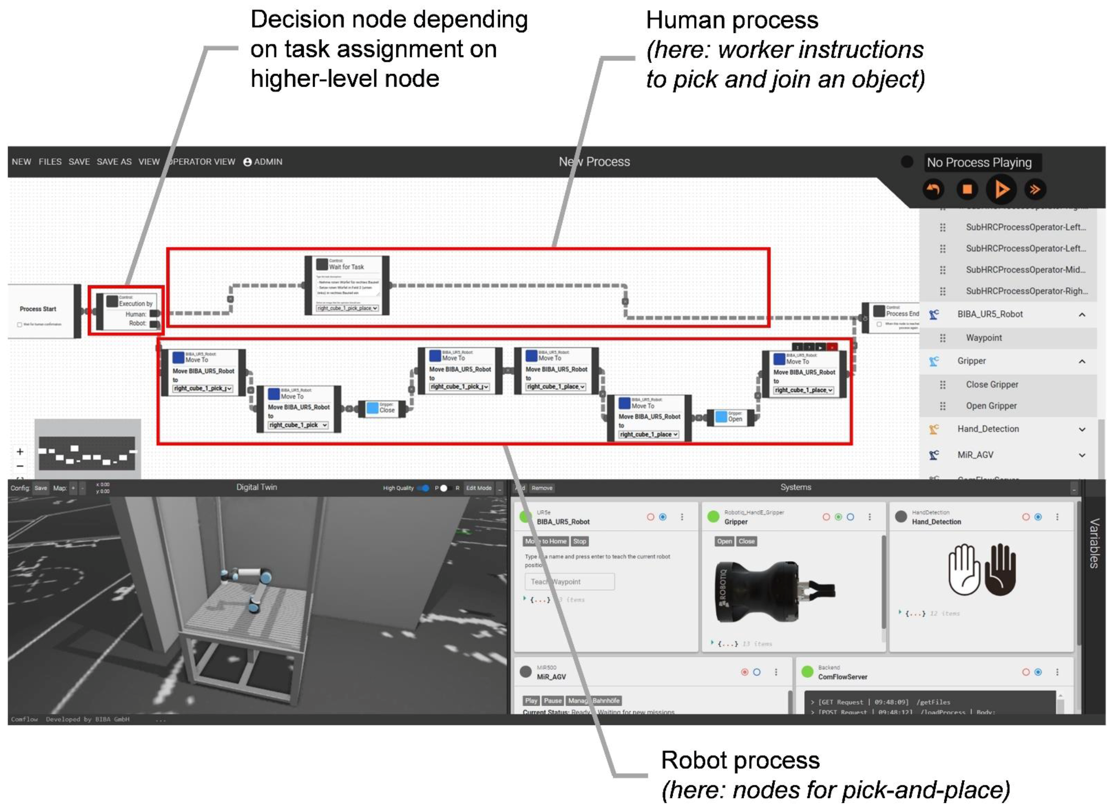
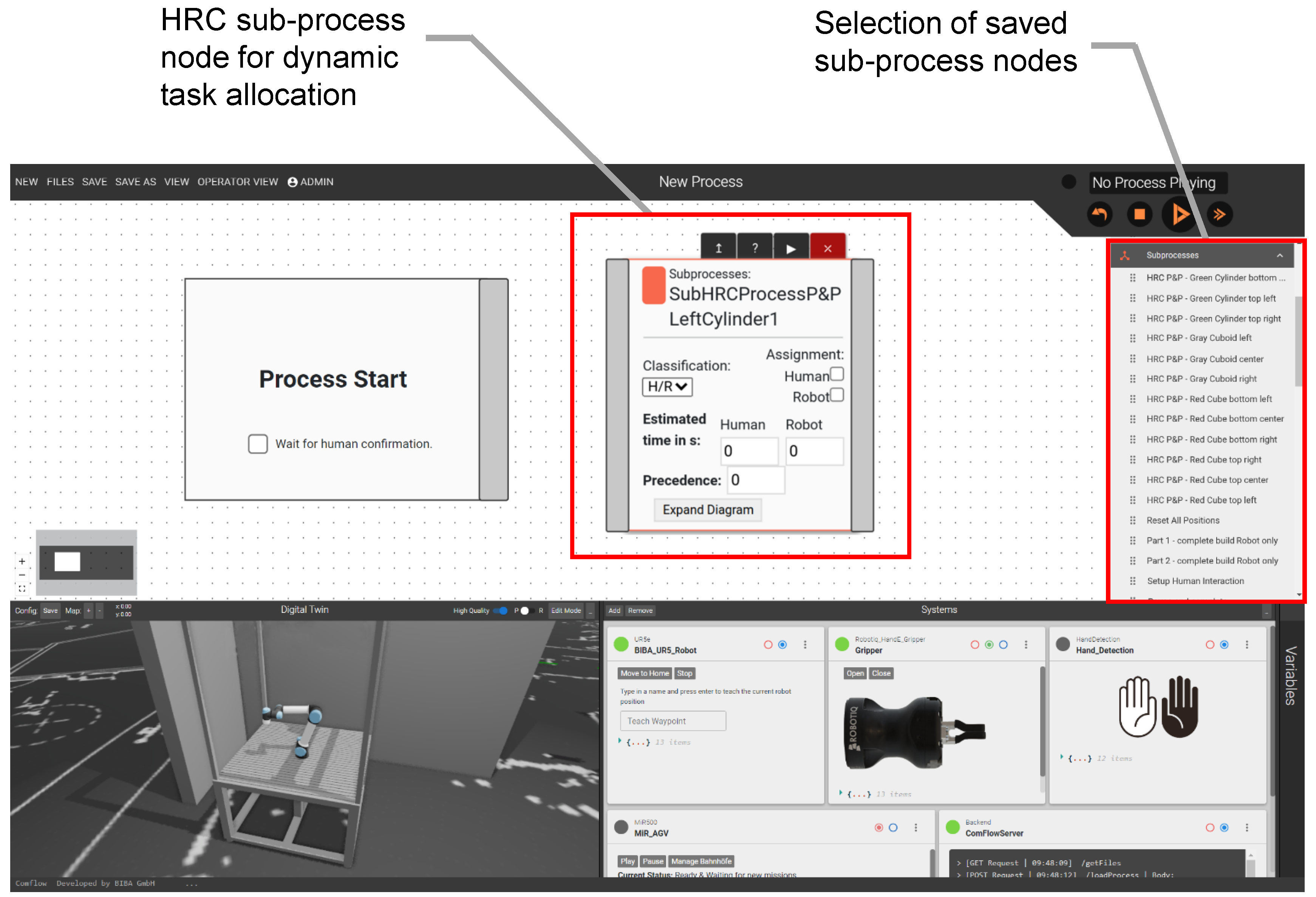
Figure 8 and Figure 9 show the user interface of the ComFlow framework with the implemented nodes for HRC task allocation. The task creation, i.e., the creation of HRC sub-processes, is depicted in Figure 8. The initial decision node switches the subsequent process sequence between human and robot depending on the final task assignment according to the higher-level task allocation algorithm. The sub-process is then saved by entering a name as well as selecting the process type sub-process. For creating the overall assembly process, the saved sub-process can then be selected as a sub-process node and added via drag-and-drop, as shown in Figure 9. The HRC sub-process nodes comprise the properties explained in Section 2.2.2.
An exemplary assembly process with multiple connected HRC nodes is shown in Figure 10. After saving the process with type selection process the user can switch into the process flow viewer intended for workers and start the process execution using the process control buttons (Figure 11). As explained in Section 2.2.1, the assembly instructions for the tasks assigned to the human are displayed in the lower part of the screen and the progress of the process is visualized in the process flow viewer by changing the status color of the individual blocks.

2.3. Study Design and Evaluation Methodology

To validate the implemented system as well as the proposed algorithm for dynamic task allocation on the one hand, and to evaluate the characteristics and effects of different types of task allocation on the other hand, a user study was designed. The study design and evaluation methodology are presented in the following, starting with the experimental setup (Section 2.3.1), the assessed aspects and collected data (Section 2.3.2), the procedure of the study (Section 2.3.3), and finally the approach for data analysis (Section 2.3.4).

2.3.1. Experimental Setup and Task Allocation Modes

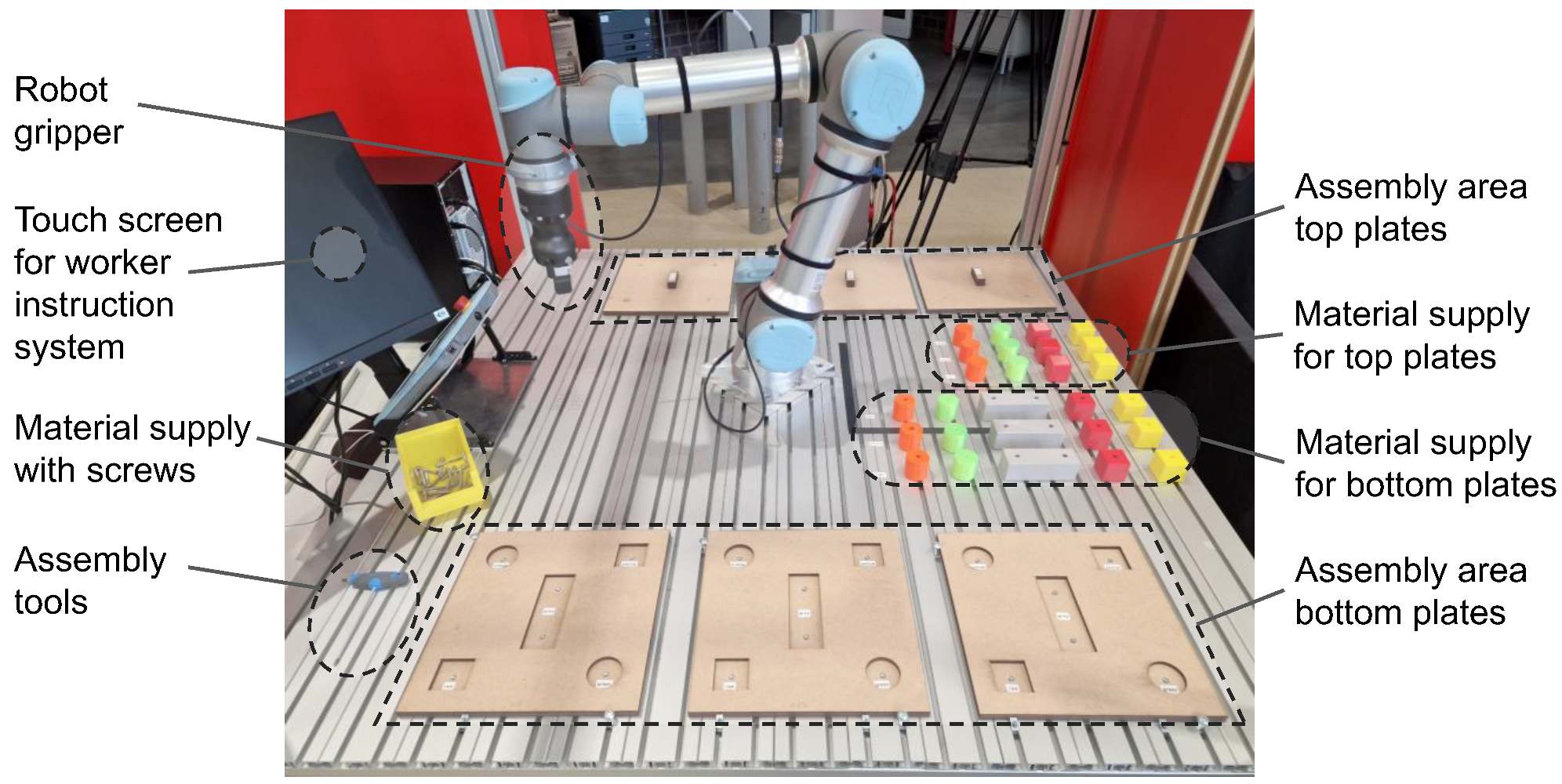
For the study, a collaborative assembly station was set up (see Figure 12), consisting of a collaborative robot (Universal Robots UR5e) with a two-finger gripper (Robotiq Hand-E gripper), which is located in the center of the assembly station, a touch screen for displaying the previously described user interface, as well as areas for material supply and assembly. The material is provided in an orderly arrangement.
A warehouse for parts, in which screws are stored, is located near the assembly station. During the study, in different setups (more details in Section 2.3.3), too few screws are deliberately provided in the material supply at the assembly station in order to simulate a delay in the assembly process. The required time to retrieve screws from the warehouse is 30 s on average.
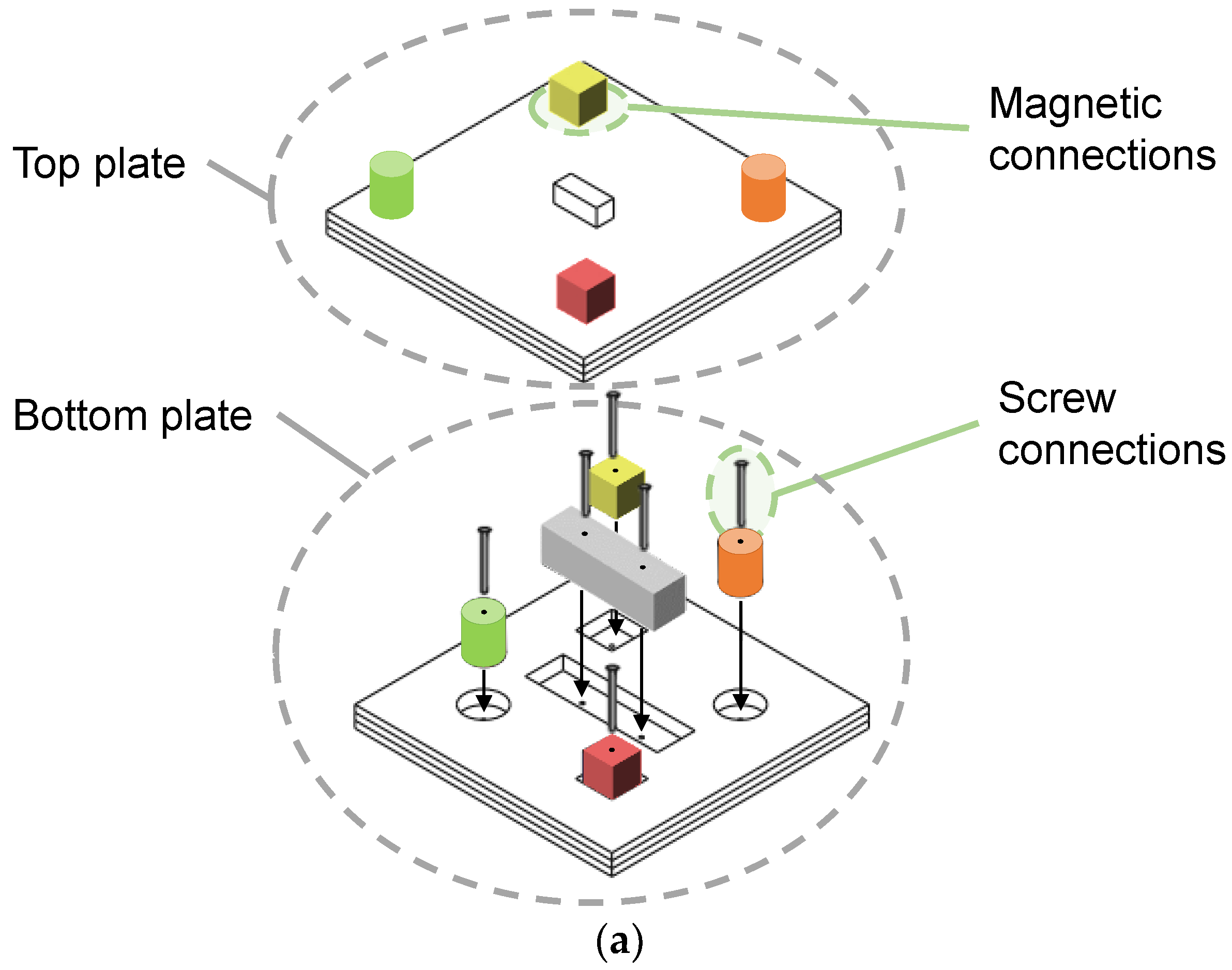
To address the potentials of assembly in human–robot collaboration, a component was designed for the study implementation whose assembly precedence graph has several process steps that can be executed in parallel. The component consists of two plates on which differently shaped and colored blocks are placed. The mounting of blocks on the plates is achieved by means of screw or magnetic connections (see Figure 13a). The plates preassembled with the blocks are then placed on top of each other and the correct fit is checked by visual inspection. A total of three components are available for the study, so that the degrees of freedom with regard to parallelism of the overall task can be adapted by simultaneously assembling multiple components. Figure 13b shows the three assembled components side by side; the assembly precedence graph for each component is shown in Figure 13c. The assembly of a single component comprises 16 process steps (pick-and-place tasks are counted as one task; the screwing tasks for the gray cuboid comprise bolting of two screws). With parallel assembly of three components, the total process therefore comprises 48 process steps.
The setup of the study’s assembly processes with the developed system follows the implementation and planning process shown in Figure 4. First, the input data are collected. In addition to the assembly precedence graph explained above, the required assembly times for each process step were estimated. Human process times were measured by observing the average process time for manual assembly execution of the first three authors of this paper. The assembly times of the robot for performing each sub-process were recorded. It is noteworthy that the human has to walk around the assembly station for executing the assembly steps for the top plate, which results in significantly faster execution times by the robot for these process steps. Additionally, the individual process steps were classified with respect to their executability by humans or robots. The classification of the assembly process steps is based on the criteria catalog proposed in [51]. Due to the relatively low automation complexity of the pick-and-place tasks (picking of rigid components in an ordered material supply as well as joining with tolerance requirements > 1 mm), these tasks were all classified as suitable for both robots and humans. As the robot is solely equipped with a two-finger gripper without the possibility of hardware reconfiguration, screwing tasks were classified as only executable by human workers. The same applies to the inspection process step, as the robot is not equipped with a vision system for optical inspection.
Next, we created the sub-processes with the respective task sequences for the human and the robot (cf. Figure 8). For the robot tasks, the required waypoints to pick-and-place each block and each top plate onto the bottom plate were taught by guiding the robot in free drive mode physically into the desired position. Then, a name was defined, and the waypoint was saved in the robot system dashboard of the ComFlow process flow editor.
After all HRC sub-process nodes were created, the assembly processes for one component, three components, and for the different task allocation modes, respectively, to be investigated in the study were created and saved (see, e.g., Figure 10 for the created assembly process of one component in dynamic task allocation mode). We defined the following four different task allocation modes that are investigated in the study:
  • Manual assembly
    Execution of the assembly process exclusively by humans. For this purpose, all HRC process nodes are classified as “human” and thus the corresponding worker assembly instructions are displayed on the screen for all steps.
  • Collaborative assembly—static task allocation with asymmetric planning
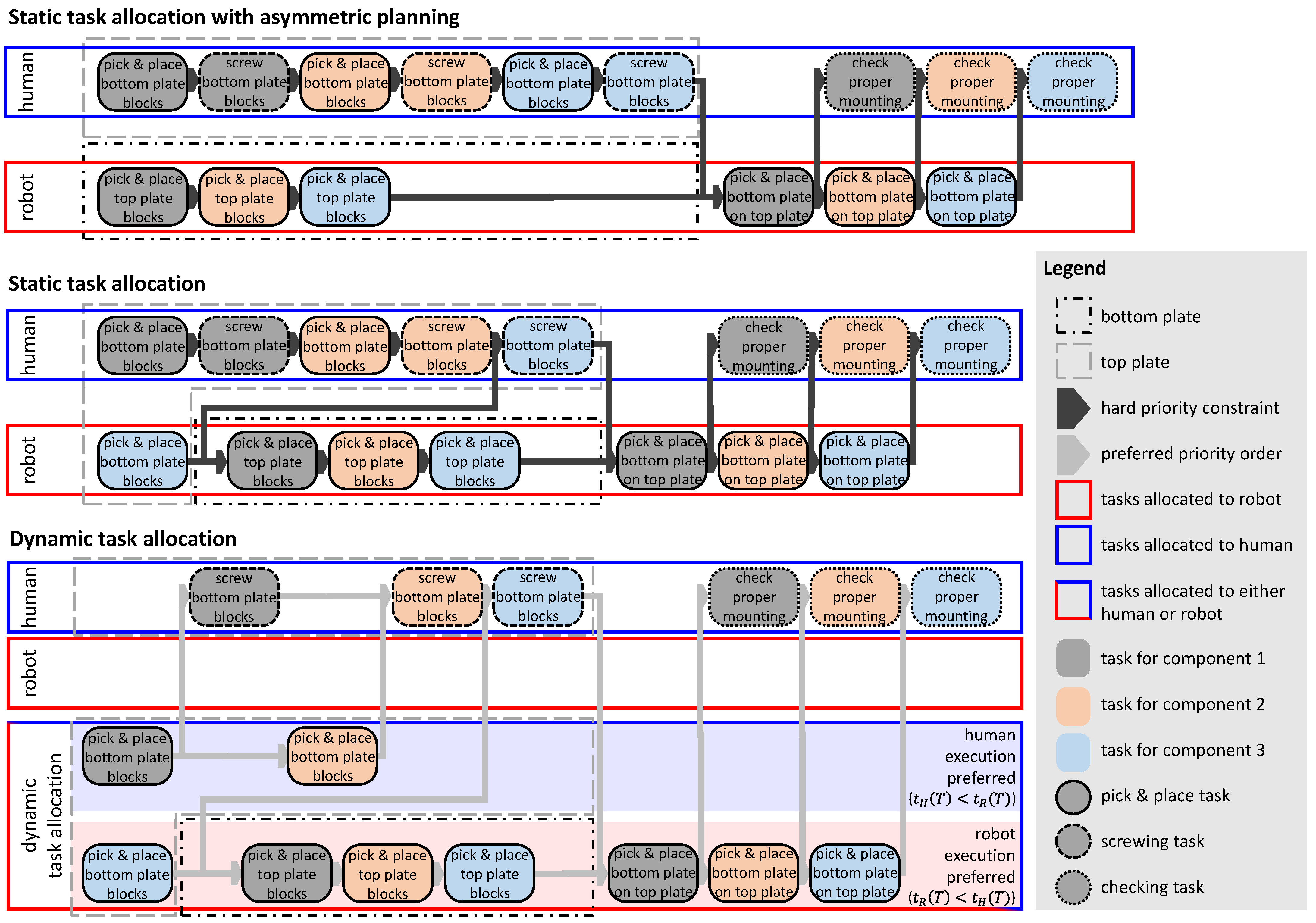
    Execution of the assembly in human–robot collaboration, with an intuitive distribution of the tasks between the resources. Here, the human takes over all assembly operations of the bottom plate and the robot executes all assembly operations of the top plate. Since the bottom plate requires additional screwing tasks, parallel sequences of different lengths are created, which is why the mode is referred to as static-asymmetric in the following for simplicity. The individual HRC nodes of the assembly process are each classified as either human or robot during process creation to allow no flexibility in task assignment. Additionally, the order in which the tasks are performed is fixed.
  • Collaborative assembly—static task allocation with time-optimized planning and iterative, experimental fine-tuning
    Execution of assembly in human–robot collaboration, with planning of task assignment based on the estimated task times, followed by testing and experimental fine tuning of the order of the sub-processes by the first three authors. Here, the robot additionally takes over the placement of the blocks on the right bottom plate, thus the estimated times of the parallel assembly sequences are harmonized. This task allocation mode requires a higher planning effort and is called static in the following.
  • Collaborative assembly—dynamic task allocation
    Execution of the assembly in human–robot collaboration, where the task allocation decision is made dynamically according to the approach for dynamic task allocation described in Section 2.2.2. The sub-processes, which can be executed in any order, are therefore not defined with a fixed sequence, but are created in parallel in accordance with the assembly precedence graph in Figure 13c. The decision about the task sequence, i.e., the selection of the sub-process to be executed next in each case, is therefore also made automatically following the logic of the explained dynamic task allocation approach. However, we set a priority P of one to three for the bottom plate preassembly tasks so that the algorithm prefers to assemble the bottom plates from left to right. The classification of the individual sub-processes is set according to the information about the executability of the step by the respective resource (human, robot, or human/robot for tasks that can be executed by both resources). The cognitive planning effort in this task allocation mode is therefore quite low, since only the input data need to be entered into the user interface.
A simplified illustration of the resulting task sequences in the different collaborative task allocation modes is shown in Figure 14 for the assembly of three components in parallel.
The manual assembly is used as the baseline mode to evaluate the general benefit of human–robot assembly in the use case scenario and is only performed for the assembly of one component. With the two different static task distributions, an indication of how the dynamic task allocation mode compares to a naïve or an optimized static planning is made possible, especially in light of different execution speeds of different subjects. Due to the longer process length, the difference in task sequence between static mode with naïve, asymmetric planning and static mode with detailed iterative planning is only significant when three components are assembled, which is why this is only examined in the setup with three components.

2.3.2. Metrics and Data Collection

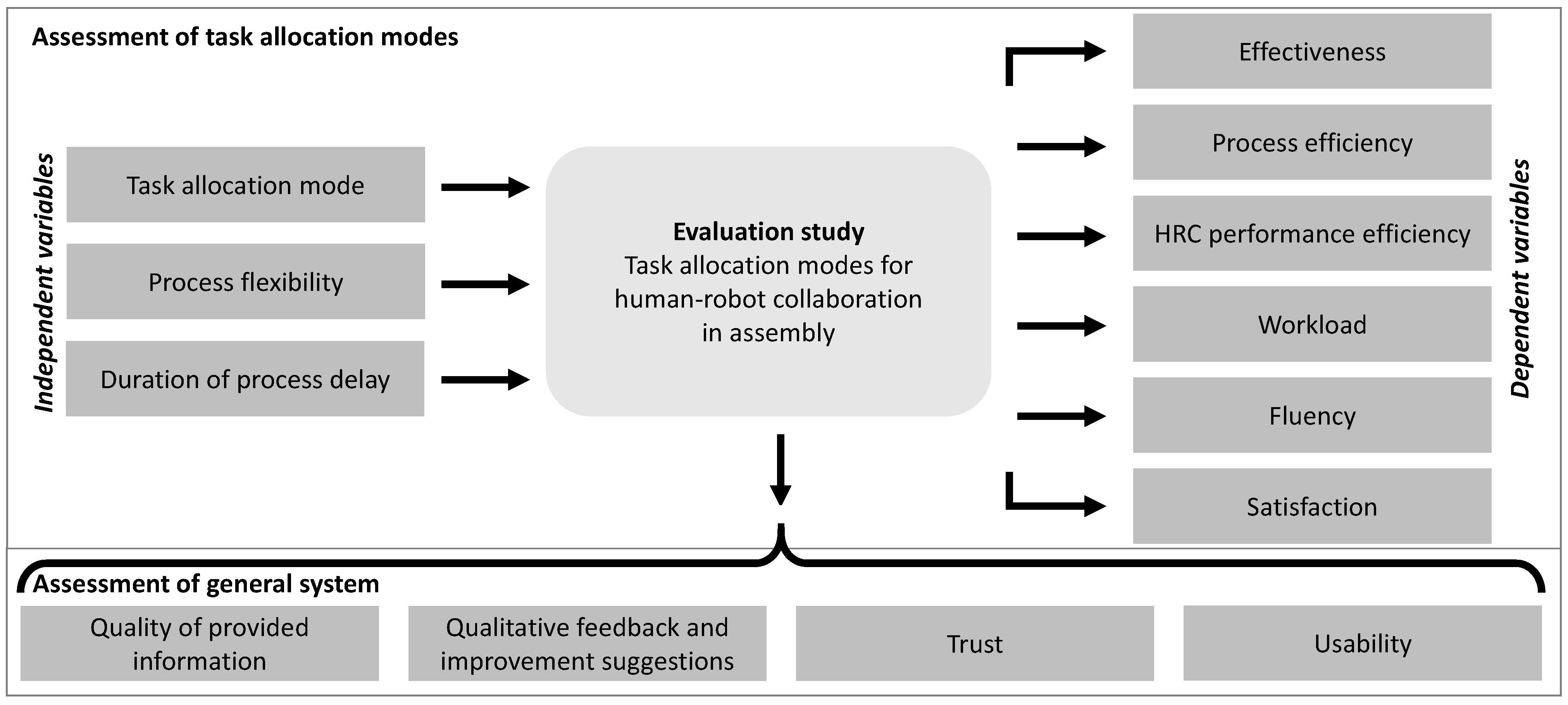
For the evaluation study, the independent and dependent variables were defined as shown in Figure 15. The study aims to examine how the different modes of task allocation explained above affect the various qualitative and quantitative aspects relevant in collaborative assembly. Moreover, the influence of a parallel assembly of multiple components (process flexibility) as well as the influence of process delays are investigated. In addition to these aspects, the proposed overall system is evaluated with respect to usability, trust in robot, information quality, and qualitative feedback.
In accordance with [52], the relevant variables in the context of collaborative human–robot assembly were classified into the aspects of effectiveness, efficiency, and satisfaction listed in ISO 9241-11 [53]. Beyond the variables proposed by [52], we have added a number of metrics for the aspect of efficiency that quantitatively evaluate HRC performance (HRC fluency [54]), as well as various investigated variables with respect to user satisfaction (or human factors, cf. [55]). Table 2 provides an overview of the variables examined with the utilized metrics and the respective approach for data collection.
The required data are collected from three sources: First, notes are taken by the study coordinator regarding successful process completions as well as errors during assembly. Second, the timestamps of the start and end times of all sub-processes including the final assignment to human or robot are saved in an automatically generated process log file. This can be used for detailed process evaluations regarding the analysis of the efficiency aspects. Third, questionnaires with radio buttons and free text input fields are used to investigate the evaluation aspect of user satisfaction.
Two questionnaires were prepared for the metrics to be collected qualitatively by user survey. The first questionnaire contains the dependent variables, which are depending on each task allocation mode (NASA raw TLX [56,57], fluency [54], and satisfaction [58]). The second questionnaire contains the general system evaluation variables (trust [59], usability [60,61], information quality [62,63], preferred task allocation mode, and qualitative feedback as well as demographic information and technical affinity [64]), and is surveyed at the end of the study session. A detailed listing of the questionnaires can be found in Appendix C. The two questionnaires were prepared with Google Forms.

2.3.3. Procedure of User Study

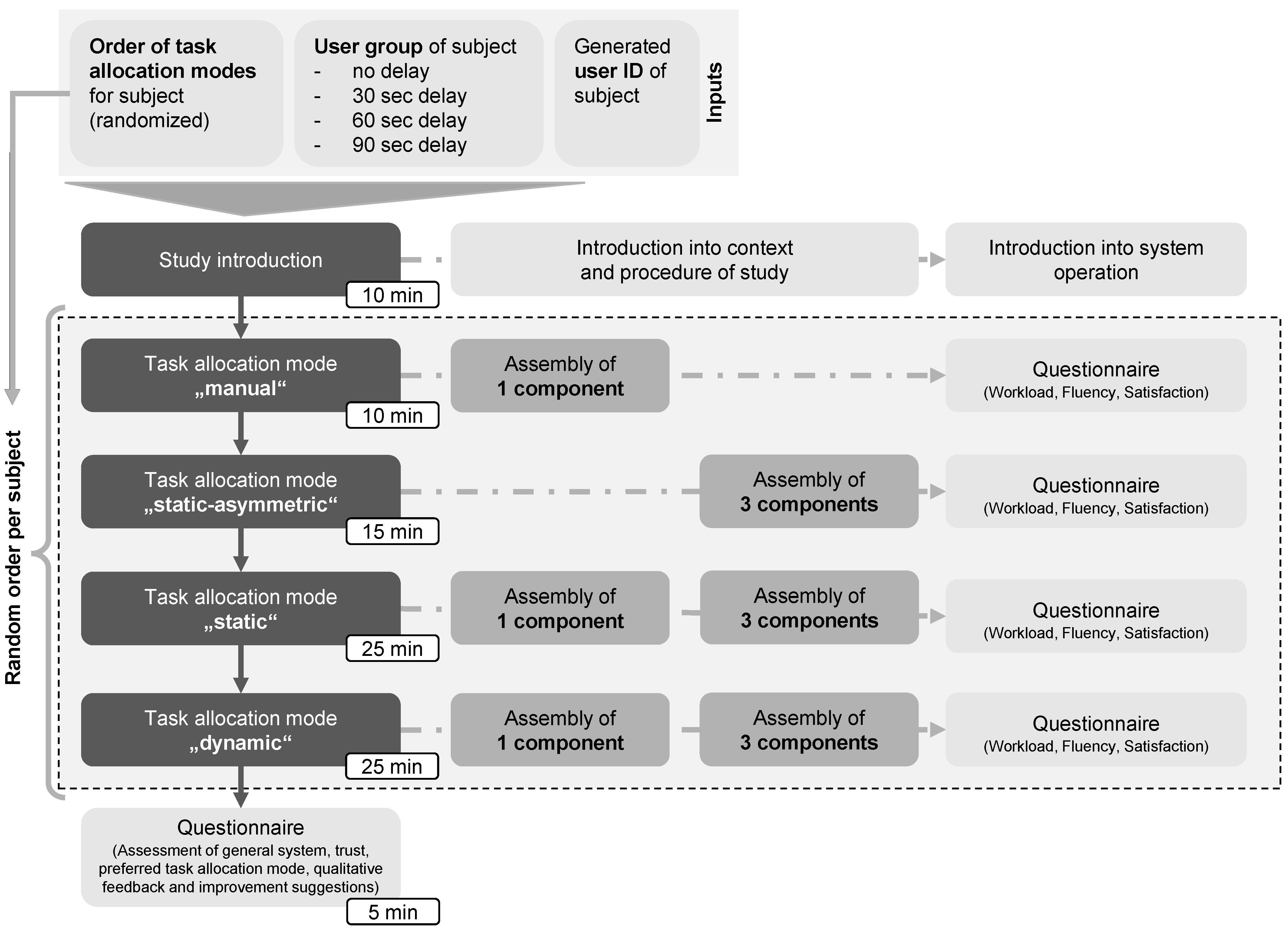
The study was conducted with a total of 20 subjects. The composition of the subjects regarding demographics, background experience, and technical affinity is presented in Section 3. For anonymization purposes, all subjects were assigned with identification numbers (IDs), which are exclusively used during the evaluation. Subsequently, the subjects were randomly divided into four user groups, in which the duration of the process delay differs (no delay, 30, 60, and 90 s delay). Furthermore, the order of the task allocation modes (manual, static-asymmetric, static, and dynamic) was randomly selected for all subjects, whereby care was taken to ensure that each mode came first, second, third, and last, respectively, with equal frequency. This was performed to reduce the influence of learning effects. After an initial pilot test, individual appointments were arranged with all 20 subjects, spread over a period of two weeks. The study was conducted by a study coordinator with the assistance of a supporting person in order to quickly perform disassembly and reset of the initial situation between the individual runs.
The study procedure for all subjects, with a duration of about 1.5 h each, is shown in Figure 16 and described in the following: First, an introduction to the context and the course of the study was given by the study coordinator. Here, it was explicitly pointed out that the study coordinator was not the person responsible for the development of the overall system or the study design to ensure honest and critical feedback from the subjects. In addition, the voluntary nature of participation was emphasized and a consent form for participating in the study was signed by the subject. This was followed by a short familiarization phase with the user interface, in which the main areas for visualization and information provision as well as the button for confirming completed process steps were shown. Moreover, subjects were instructed to carefully follow the assigned tasks and assembly instructions displayed on the screen, and to confirm each task upon completion.
After that, the assembly process was performed in the first task allocation mode according to the random, subject-dependent order. Within each task allocation mode, the assembly was performed first with one and then with three components (in the manual and static-asymmetric mode, only one component and three components, respectively, were assembled). An exemplary illustration of a complete process flow of collaborative assembly execution is shown in Appendix B. By starting the assembly process execution, automatic data logging of the process times and final task assignments takes place. Depending on the duration of the delay, the screws initially available in the assembly station were deliberately too few, so that the subject had to collect the screws needed from the warehouse during the assembly process either once (30 s delay), twice (60 s delay), or twice with an extended pause, instructed by the study coordinator (90 s delay). After completing the assembly runs in the respective mode, the subject was asked to complete the short questionnaire (see Appendix C.1). Meanwhile, the study support person restored the initial state of the experimental setup.
The other three task allocation modes were performed in the same way. In total, six assembly runs were carried out by each subject. After completing all assembly runs, the final questionnaire (see Appendix C.2) was filled out by the subject.

2.3.4. Data Analysis and Evaluation Process

The data analysis and evaluation are composed of two parts. First, the process log files of the assembly execution were evaluated (the raw files can be found in the Supplementary Materials). For this purpose, an evaluation script was implemented in a Jupyter notebook. In addition to the total process time, this script calculates the number of human and robot tasks, the idle time of the human and robot, and the concurrent activity time of the two resources (time during which both the human and the robot perform a task in parallel) based on the individual sub-process timestamps and the information about the final task assignment. Additionally, Jupyter notebook was used to generate the graphs and Gantt charts presented in Section 3. Second, the evaluation of the questionnaire responses was conducted using Microsoft Excel. The individual scores were calculated according to the explanations in Appendix C on the procedure for the respective score assessment.

3. Results

Details on the composition of the 20 subjects participating in the user study in terms of gender, age, education, experience in the field, and technical affinity are shown in Table 3. The subjects, who were unfamiliar with the system, are composed of academics and undergraduates. They have a rather high technical affinity, and more than half have prior experience in the field of assembly.
The results of the investigated variables in the study are reported in the following sections, presented in the order of the evaluation aspects as listed in Table 2.

3.1. Effectiveness

All subjects were able to successfully complete all assembly runs of the study (process completed and components correctly assembled), i.e., TCR = 100 % .
During the assembly process, however, some of the subjects made mistakes (hereafter referred to as errors) that were either corrected immediately (e.g., picking up the wrong part) or were not relevant to the successful completion of the assembly (e.g., joining and screwing were performed in immediate succession, without confirmation in between). We categorized the errors into three types—picking errors (e.g., wrong part gripped), assembly errors (e.g., wrong task performed), and operator interaction errors (e.g., forgotten confirmation).
During the total of 120 runs, a total of 36 errors occurred, which were composed as follows: n err picking = 10 ; n err assembly = 14 ; and n err confirmation = 12 . The errors made by the individual subjects mainly occurred in the first two runs of the study, which can be explained by learning effects. Other errors are evenly distributed across the runs and subject groups, implying that neither the task allocation mode nor the duration of delays have a significant effect on the number of errors. Most errors resulted from inattentive observance of the assembly instructions. As all errors were either uncritical for a successful component assembly or were noticed and corrected by the subject itself, they had no effect on the TCR . However, they do have relevance against the background of quality assurance.

3.2. Efficiency

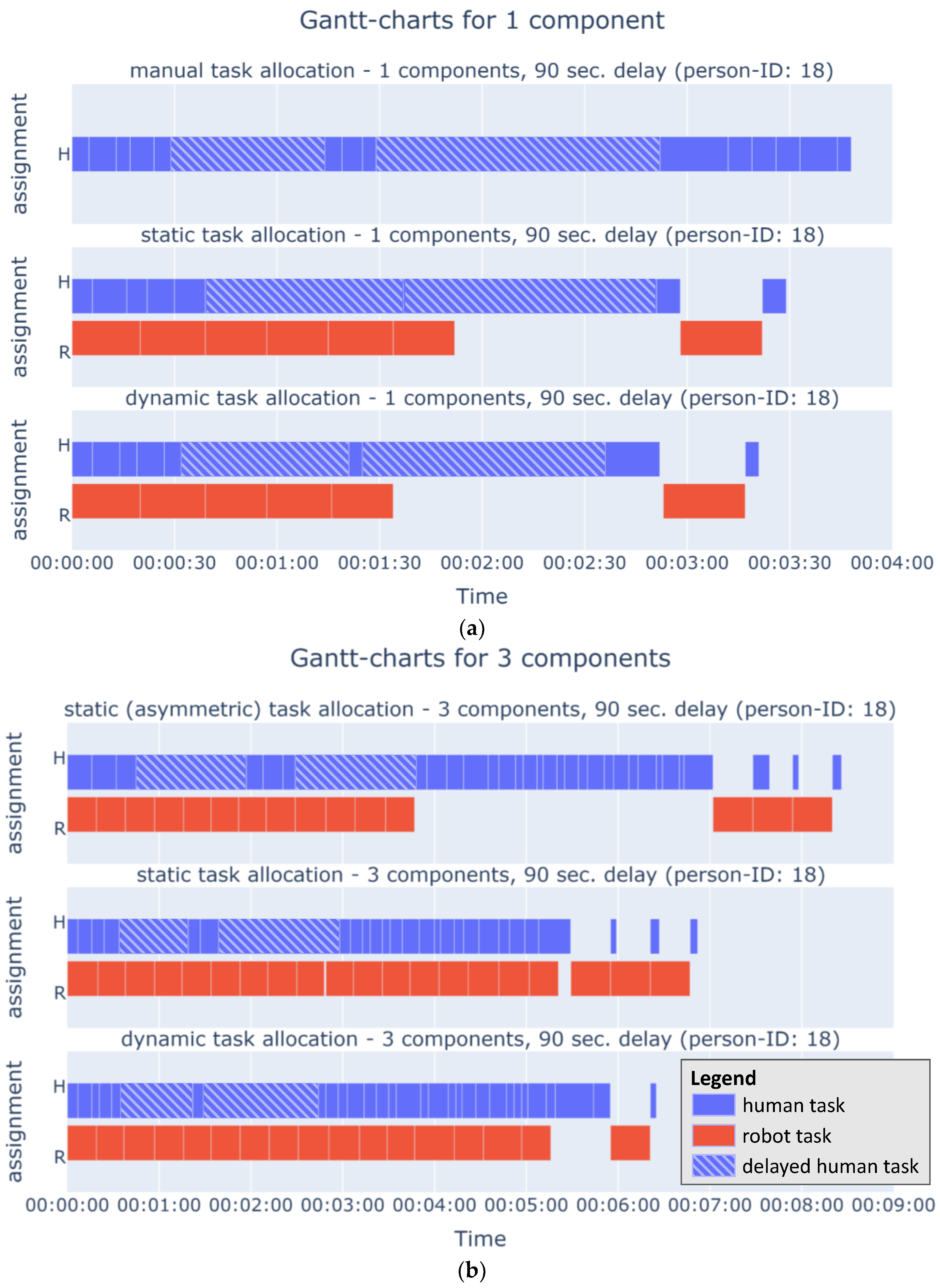
For a better understanding of the following analysis results regarding the evaluation aspect of efficiency and to illustrate exemplary process flows, Figure 17 shows the Gantt charts for the assembly of one component and three components, respectively, in the different task allocation modes of the study for an exemplary subject. Delays of sub-processes due to the necessity to collect screws from the warehouse for further assembly execution are shown hatched.

3.2.1. Assembly Process Time

An overview of the resulting mean assembly process times for the different task allocation modes is given in Table 4, clustered by the number of components and the duration of the delay.
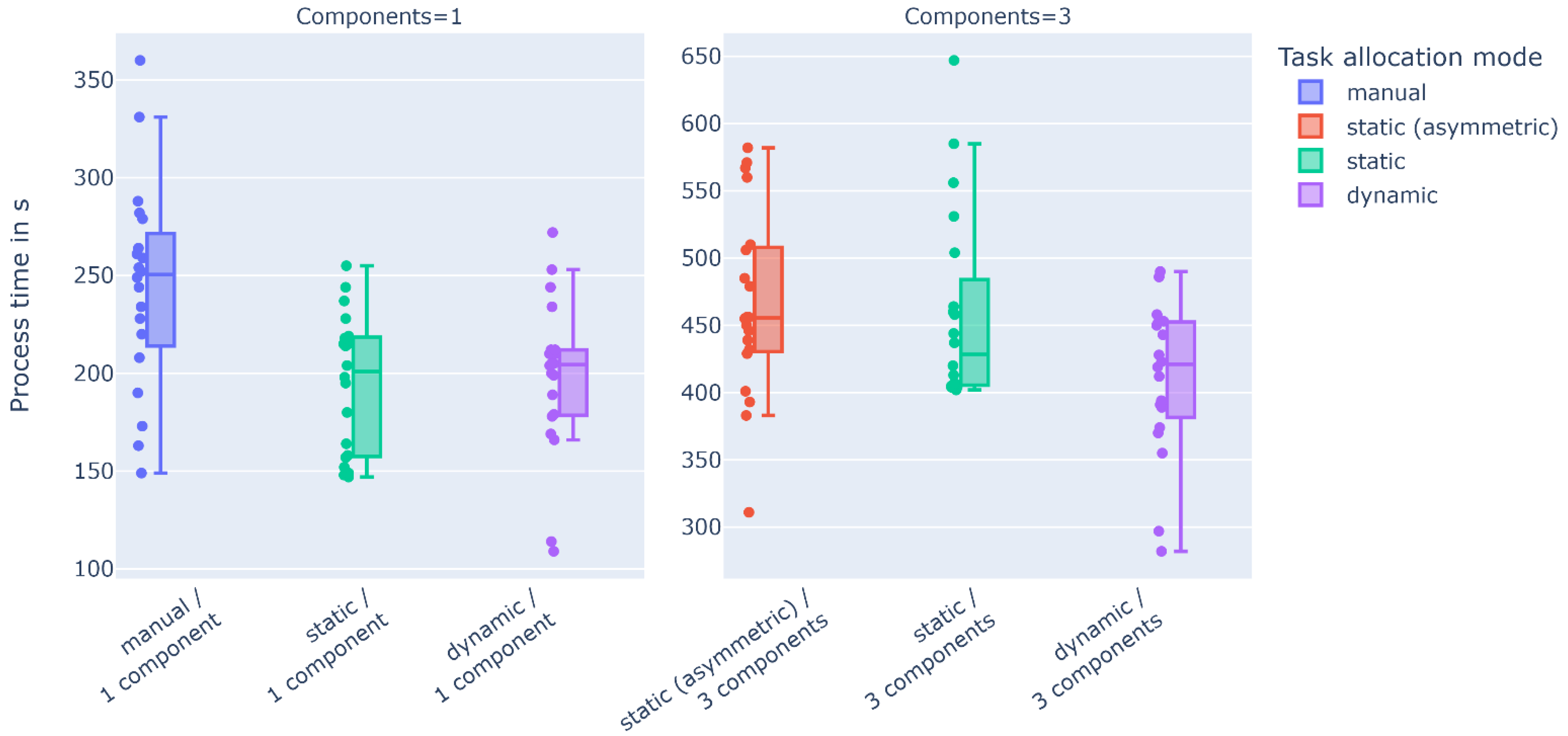
As follows the assembly process times for one component from Table 4, the execution of the assembly in human–robot collaboration reduces the cycle time in the user study by 19.2% in dynamic mode and 20.4% in static mode compared to manual assembly. For the assembly of one component, the assembly process times for the static and dynamic task allocation mode are similar.
The potentials of dynamic task allocation only take effect when the degree of parallelism of the overall process is higher, i.e., when three components were assembled in the study. The process time decreases by 10.2% on average compared to static task allocation with optimized planning and by 11.7% on average in comparison to static-asymmetric task allocation (i.e., with an intuitive, simple planning of the task assignment), when using dynamic task allocation. This relationship also becomes evident from the graphical illustration in Figure 18.
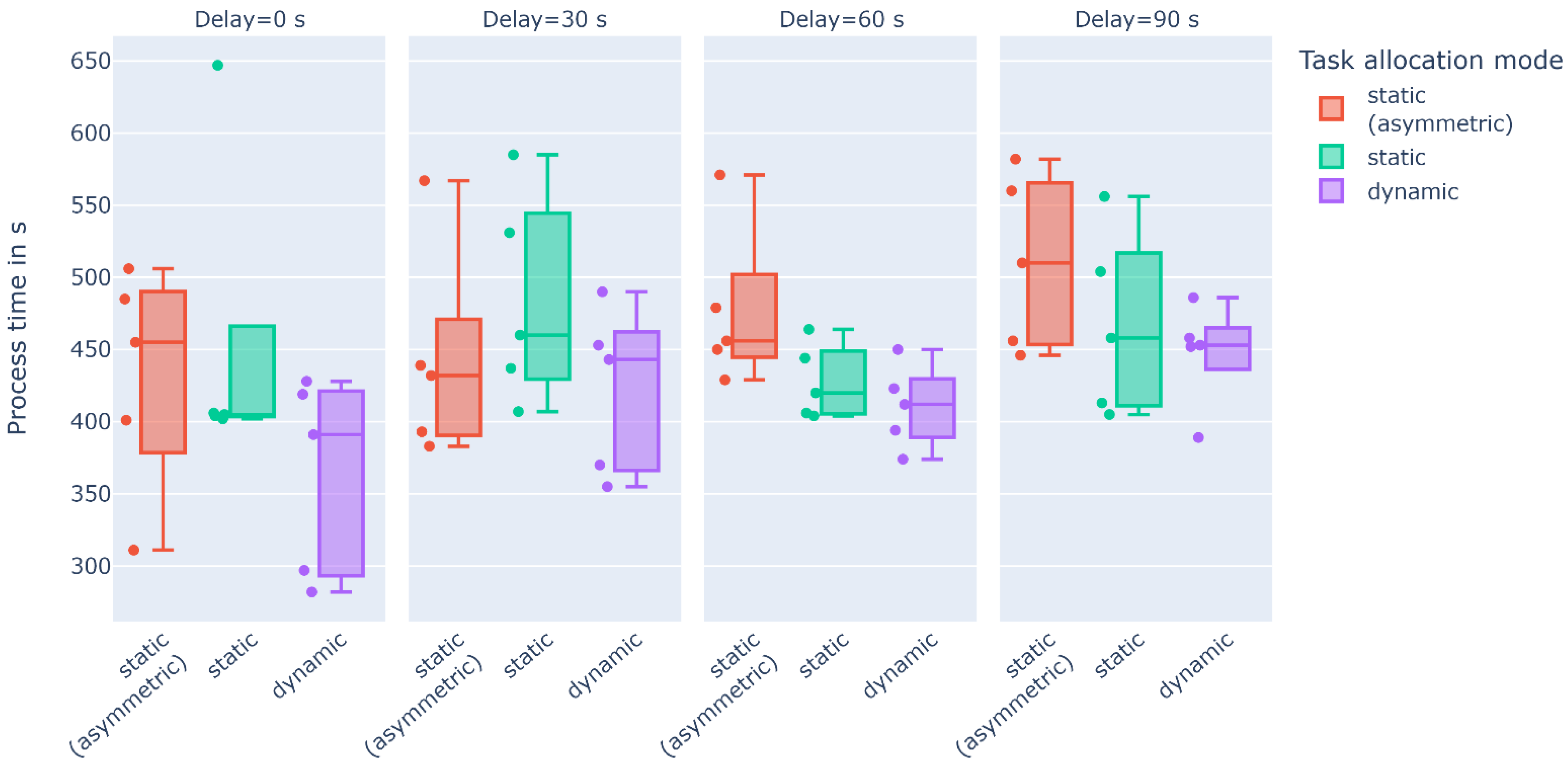
The effects of the duration of delays in the different task allocation modes are shown in Figure 19 for the assembly of three components. In general, the total process time increases with increasing delay duration in all modes. The delay was set at the beginning of the parallel sequences of the total process in all runs (cf. Figure 17). Due to the limited number of subjects per delay group, however, no reliable statement can be drawn here about the ability of the different task allocation modes to compensate for delays in terms of cycle time, and thus remains a subject for future research.

3.2.2. Quantitative Assessment of HRC Performance and Fluency

Figure 20 shows the results of the quantitative analysis of the key performance indicators (KPI) for HRC performance and HRC fluency (number of human and robot tasks, human and robot idle time, and concurrent activity time) for the different task allocation modes, depending on the duration of the process delay.
Considering the number of tasks allocated to the human and to the robot, it is evident that in both static task allocation modes—due to their static nature—the number of tasks remains constant regardless of the duration of delays. In the dynamic mode, a reduction in the human tasks in favor of the robot can be observed with increasing delay time of the human tasks. Compared to static task allocation, this results in lower waiting times of both resources as well as in a higher concurrent activity time, which even increases with longer delays. On the one hand, this validates the functionality of the proposed dynamic task allocation approach. On the other hand, as all variables relevant for HRC fluency achieve better results, a quantitatively better HRC fluency of the dynamic task allocation mode, compared to the two static task allocation modes, can be concluded.

3.3. Human Factors and User Satisfaction

The evaluation of the data collected by means of questionnaires is presented in this section—first for the metrics depending on the task allocation mode (Section 3.3.1), followed by the metrics for evaluating the developed system itself (Section 3.3.2).

3.3.1. Variables Depending on Task Allocation Mode

An overview of the results for workload, fluency, and satisfaction is shown in Table 5 for the different task allocation modes. Regarding the workload, the interpretation of the RTLX score shows a medium-level workload (see [65] for summary on interpretation of the NASA TLX score) perceived by the subjects in all setups. In both static task allocation modes, the workload is lower than in manual task allocation and dynamic task allocation modes. An examination of the answers to the individual questions shows that this is mainly due to the higher mental workload in both cases, due to the higher pace of the task in the case of dynamic task allocation, and due to the need for harder work to accomplish performance in the case of manual assembly.
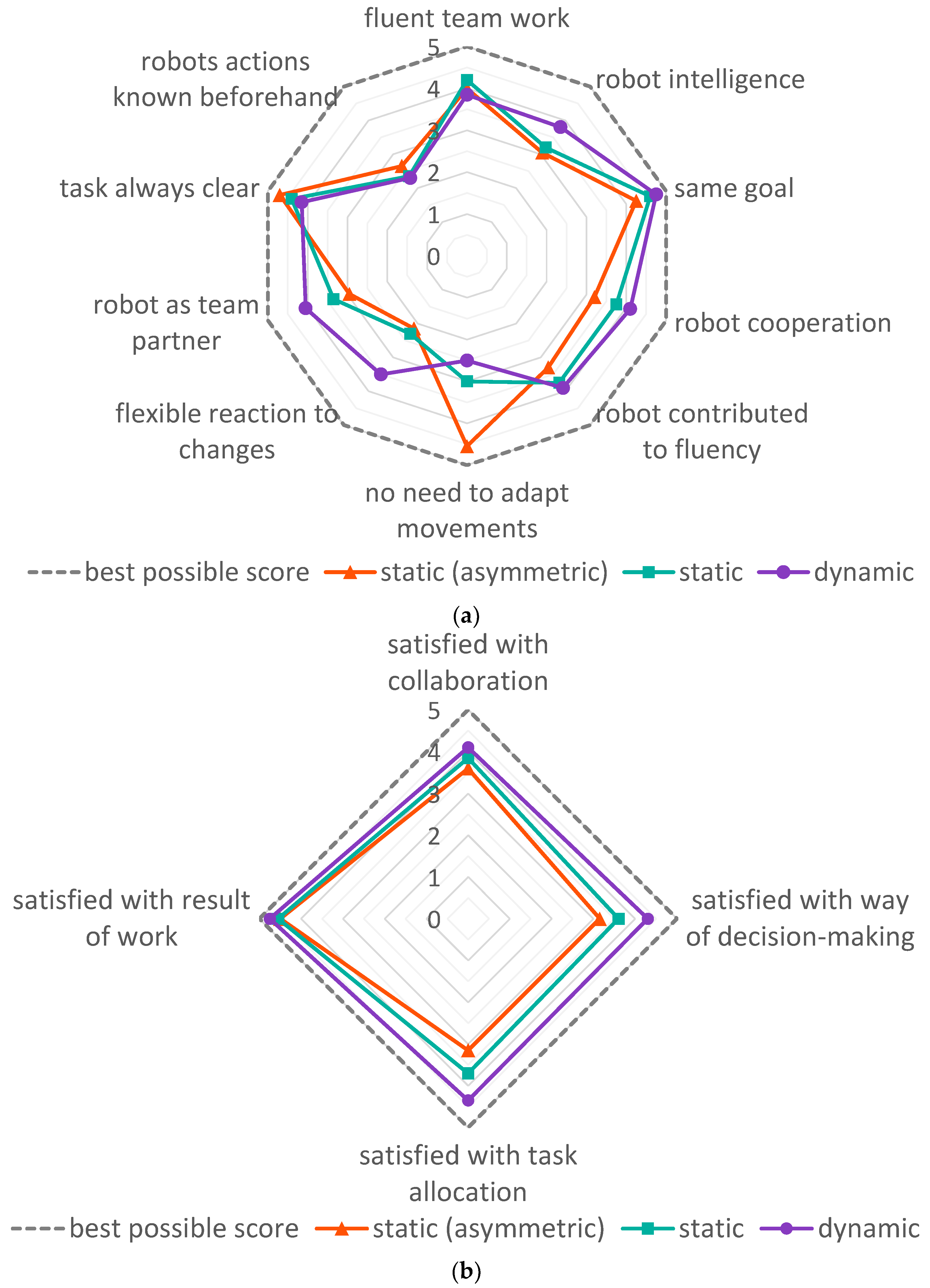
The subjective evaluation of HRC fluency shows almost identical fluency in both static task allocation modes, while in the dynamic task allocation mode, fluency was reported to be slightly better (cf. Table 5). When analyzing the feedback in detail (see Figure 21a), the intelligence of the robot, the perception of the robot as a team partner, and the flexible reaction to process changes are rated significantly better in the dynamic task allocation mode. However, the need of the human to adapt their own movements to the robot is rated worse in dynamic task allocation. This can be explained by the less clearly defined sequence of robotic tasks resulting in less predictable robot movements.
The satisfaction assessment reveals a significantly higher satisfaction score in the implemented approach for dynamic task allocation, where in particular the satisfaction with the resulting task assignment is markedly perceived best (cf. Figure 21b).
Figure 22 shows the subjective user preference regarding the preferred mode of task allocation. A clear preference for the dynamic task allocation can be observed, which is judged as the preferred mode by 75% of the subjects.

3.3.2. General Assessment of the System

In Table 6, an overview of the resulting scores measured for general system assessment, i.e., system usability, information quality, trust in robot, and the subjects’ feedback about their willingness for permanent usage of the system for collaborative assembly are given.
The developed system achieves an SUS score of 79.4, which is interpreted as a grade A, i.e., a good system usability (see [61]). The quality of provided information achieves high feedback in terms of accuracy, relevancy, and representation. Despite an acceptable score, needs for improvement were identified in the ease of information extraction. This was also mentioned by some subjects in the suggestions for improvement.
In terms of trust in the robot, a high score of 43.3 was achieved. According to [59], this is an almost optimal trust result, as the score is high, but not too close to the maximum value of 50, which would indicate that the subjects are overly relying on the robot, potentially leading to complacency.
Finally, this positive overall assessment of the developed system was further confirmed by the statement of 85% of the subjects who can envision a permanent use of the system for collaborative assembly, indicating a good system acceptance.

4. Discussion

The conducted user study demonstrated the potentials of HRC for assembly processes that allow a certain degree of parallelism in the execution of sub-processes. Within the study, we found a reduction in cycle time of approximately 20% compared to manual assembly. This is relatively consistent with the results of [38], who reported a reduction in cycle time of approximately 25% for a similar amount of process steps (16 tasks in [38]; 14 tasks in conducted study for assembly of one component). Another interesting finding is that dynamic task allocation can only exploit its potential at a certain degree of parallelism (process flexibility) in the assembly process to outperform static task allocation. Assembly processes that do not have these degrees of flexibility may be adapted through the parallel assembly of a higher number of components. This also avoids the reported problem of operators having to adjust their movements, as the resources can perform their respective tasks in parallel on several components, which in turn reduces cycle time by reducing waiting times.
Both the quantitative and qualitative results of the study further indicate a better fluency of the HRC assembly when using dynamic task allocation. In particular, in the event of delays during the process execution of one resource, the other resource is not forced to wait, but can instead continue with the execution of remaining unfinished tasks. This is especially reflected in a significantly higher concurrent activity time in dynamic task allocation compared to static task allocation. This characteristic also enables dynamic task allocation—for processes with a correspondingly large number of sub-processes that can be executed by both humans and robots—to flexibly adapt to the individual worker, independent of its task execution performance, without the need for specific planning or programming. Consequently, even performance fluctuations during the day can be compensated.
Furthermore, some subjects also commented that they were stressed if the robot had to wait for them, which underlines the importance of a high concurrent activity time and a low robot wait time.
In terms of quantitative analysis, there remains a need for research to investigate how exactly delays in the process can be absorbed by each task allocation mode. A study specifically designed for this purpose should be conducted as future research, which systematically takes into account different time points of interruption during the process with a large number of subjects and even considers longer durations of delay than 90 s.
A reduction in the planning effort can generally be noted when using dynamic task allocation with the presented system. For realizing assembly processes in this task allocation mode with the proposed software framework, only a transfer of basic input information (process times, assembly priority graph, and task classification regarding the feasibility for execution by humans or robots) is required, which is typically available or would also have to be collected as a first step in static planning. Compared to static task allocation, neither detailed prior process scheduling nor an experimental fine-tuning of the planned processes are required.
With regard to the repeatability of the conducted study, identical conditions can be maintained with respect to the experimental setup and study procedure. Due to the characteristics of a user study, the individual absolute execution times and answers to the questionnaires depend on the respective performance of each subject, or their current daily form. Nevertheless, considering the number of subjects, it can be assumed that the core results found would remain the same overall if the experiment were repeated.
Limitations of the study particularly include the influence of learning effects, which will have occurred within the study despite randomized selection of the execution order of task allocation modes in the individual runs. Further, the study was conducted with users with an academic background who, despite their prior experience, should rather be considered as novice workers in assembly. Thus, performance and subjective perception from expert users working in industrial assembly might differ. Moreover, due to the comparatively simple assembly component, occurring worker errors did not affect the overall task completion rate. Therefore, we propose to conduct a separate study on the assembly of many components one after another over a longer period to investigate if the greater variance in task execution under dynamic task allocation affects the number of worker errors.
In the conducted study, some subjects already mentioned less monotonous work in the dynamic task allocation mode. With the abovementioned long-term study, a more profound evaluation of the effects of different task allocation modes on the monotony of assembly work over a longer period of time would be possible.
From the results of the general investigation of the developed block-based HRC task allocation system, a positive assessment can be derived. However, various suggestions for improvement were provided by the subjects: Regarding the interaction modality, some subjects suggested an acoustic signal when assigning a new task to the human. In addition, a more intuitive form of visualization of the assembly instructions, e.g., by projection directly onto the worktop, was proposed. Furthermore, an automatic, camera-based recognition of completed steps was mentioned as desirable. In terms of collaboration with the robot, the ability of the robot to dynamically avoid crossing trajectories on the one hand and the projection of the robot’s planned trajectories into the workspace on the other hand were suggested.
Additional potential for further development of the presented overall system for dynamic task allocation arises with regard to the observability and stability in the event of robot malfunctions. The state transition in a function block from “in execution” to “completed” is to be regarded as a black box during execution. Only as soon as the human confirms the successful completion or the robot reports the task-completed state, the state transition to “completed” occurs. In this way, the overall assembly process is controlled by means of the created process graph in combination with the task allocation decision methodology as well as the operator feedback inputs, or robot state messages. Dynamics that arise within the function blocks during execution are not explicitly considered. Some of these dynamics, such as interfering trajectories of humans and robots, often result in delays of the respective function block and are therefore implicitly taken into account by the dynamic task allocation approach when assigning the next tasks. However, limitations arise in certain situations: In the implemented algorithm, currently, no handling of error states within the individual function blocks is taken into account, i.e., if the robot fails during a task execution, the function block cannot transition to the completed state, so that the overall assembly process does not terminate. The same applies to human process execution: Here, the correct confirmation of all executed process steps is relied on. Incorrect confirmations or execution of other process steps than assigned lead to incorrect assumptions of the system about the progress and the state of the overall process, resulting in the inability to assign the correct next process steps. Continuous observation of the process execution by means of a camera system in combination with appropriate algorithms for activity recognition and progress monitoring could enable the observability within the function blocks. This would allow an early reaction to emerging problems and therefore offers potential for further research activities. In this context, another planned enhancement for the system is to implement a dedicated error handling output for each function block. This output is intended to be activated only in the event of an error during the function block execution (in the simplest case, e.g., via an adjustable timeout value per function block) and then trigger correspondingly connected subsequent functions in reaction to the error.
Regarding the choice between manual assembly and collaborative assembly with static or dynamic task allocation, the following can be stated as a rough indication from a process perspective: In strictly sequential assembly processes, where there is also no possibility or intention for parallelization, manual assembly is often the most suitable. With increasing parallelism, e.g., through preassembly of sub-assemblies, and increasing degrees of freedom in the process, either static task assignment or, in the case of large degrees of process flexibility, dynamic task allocation should be preferred. The latter is also recommended with regard to higher HRC fluency, especially if process delays are expected to occur regularly during assembly.

5. Conclusions

This article presented an approach for dynamic task allocation and its implementation into a block-based software framework for integrated process creation and execution. By combining intuitive block-based programming with the proposed dynamic task allocation approach, which requires only basic information input, we facilitate both the creation and planning of dynamic HRC processes as well as their adaptation to different use-cases. The proposed dynamic task allocation approach is evaluated in an extensive user study and compared to manual assembly as well as collaborative assembly with static task allocation. With the design of the evaluation study, we suggest a comprehensive systematic framework for evaluation of HRC assembly processes. The user study resulted in new insights for collaborative robotics concerning the potentials of dynamic task allocation. For one thing, dynamic task allocation reduces the overall cycle time compared to both manual assembly and static task allocation, given a high degree of parallelism in the assembly processes. For another, it increases HRC fluency in general and, in particular, in the event of deviations or delays during the assembly process.
In our future research, we aim to further assist both the planner and the operator by implementing an automatic import function for the planner that creates the dynamic HRC process based on the process input data to further simplify and quicken the process creation. For improved support of the operator, we focus on the implementation of the suggestions for system improvement obtained in the user study.
Further research needs are a long-term study of dynamic task allocation over multiple weeks with expert workers in real industrial environments, the investigation of the influence of different time points of process delays, and the analysis of errors in different task allocation modes for complex industrial components.

Supplementary Materials

The following supporting information can be downloaded at: https://www.mdpi.com/article/10.3390/app122412645/s1, Raw data S1: Videos showing the exemplary demonstration of the process execution by the author C.P. in all six combinations of task allocation modes and number of components; Raw data S2: Log files of the process execution for all subjects; Raw data S3: Responses of all subjects to questionnaires.

Author Contributions

Conceptualization, C.P.; methodology, C.P.; software, C.P., D.N., B.V. and M.S.; validation, C.P. and D.N.; formal analysis, C.P.; investigation, C.P. and E.M.; resources, C.P. and M.F.; data curation, C.P. and E.M.; writing—original draft preparation, C.P.; writing—review and editing, C.P., D.N., B.V., E.M. and M.F.; visualization, C.P.; supervision, C.P. and M.F.; project administration, C.P. and M.F.; funding acquisition, C.P. and M.F. All authors have read and agreed to the published version of the manuscript.

Funding

This research was funded by the European Regional Development Fund (EFRE) and the Bremer Aufbau-Bank (BAB), Germany, as part of the project “KoMILo—Context-dependent, AI-based interface for multimodal human-machine interaction with technical logistics systems”, grant number FuE0637B. The APC was funded by the Staats- und Universitätsbibliothek Bremen (SuUB), Germany.

Institutional Review Board Statement

Ethical review and approval were waived for this study due to anonymized data collection. Moreover, the focus is not on humans but on the technical system. No clinical or epidemiological studies were conducted on humans, on samples taken from humans, or on identifiable person-related data; thus, the study does not need approval from an ethical committee in the state of Bremen (https://www.uni-bremen.de/fileadmin/user_upload/sites/referate/referat06/3.1.6._EthikO__17.12.2015_.pdf; https://www.uni-bremen.de/rechtsstelle/ethikkommission). This is also in accordance with the guidelines of the DFG, German Research Foundation (https://www.dfg.de/foerderung/faq/geistes_sozialwissenschaften/index.html#anker13417818) (all webpages accessed on 11 November 2022). Furthermore, all individuals were informed about the data collected as well as their anonymization, participated voluntarily, and signed a consent form to participate in the study.

Informed Consent Statement

Informed consent was obtained from all subjects involved in the study and participation to the study was voluntary.

Data Availability Statement

The data presented in this study are available in the Supplementary Materials.

Acknowledgments

The authors would like to thank Kader Barat for the manufacture of the assembly components used in the study and Tanja Fortman for supporting the study by setting up the initial setup again between each assembly run. Further, the authors express their gratitude to all subjects who took part in the study.

Conflicts of Interest

The authors declare no conflict of interest.

Appendix A

Table A1. Overview of related task allocation methods and their evaluation approaches. Task allocation methods that have been evaluated in user studies are highlighted in light grey.
No.Ref.ClassificationYearProposed Task Allocation ApproachEvaluation ScenarioNo. of TasksEvaluation ApproachMain Evaluation Result
1[36]static2022optimization algorithm for planningMold assembly use case including required tool changes (scenario extracted from online video)13Simulation-based evaluation comparing different assembly setups:
-
Manual;
-
Human–robot (H-R);
-
Human–two-robot (H-2R).
H-R/H-2R process:
-
Reduces time by 2/5% over manual assembly;
-
Reduces MSD risk from medium to low/negligible risk over manual assembly.
2[35]static2019planning method with guided assistance softwareIndustrial use case of linear actuator assembly 10Demonstration of planning processValidation of planning approach
3[27]static2016planning methodIndustrial use case of aircraft fuselage shell element assembly 16Demonstration of planning processValidation of planning approach
4[26]static2022planning methodIndustrial use case of touch-screen cash register assembly35Demonstration of planning processValidation of planning approach
5[41]static2018planning method with simulation toolIndustrial use case of brake disc assembly28Demonstration of planning process Validation of planning result in simulation and laboratory setupValidation of planning approachH-R process:
-
Increases total assembly time by 17% over manual assembly;
-
Improves ergonomics.
6[37]static2022optimization algorithm for planningLaboratory use case of HDD disassembly14Demonstration of process planning algorithm for disassembly scenario with different processing periodsValidation of implemented optimization algorithm for task allocation
7[38]static2018optimization algorithm for planning with simulation toolIndustrial use case of a workplace in automotive final assembly line14Demonstration of task allocation algorithm in simulationValidation of simulation tool and optimization algorithm for task allocationH-R process:
-
Reduces time by 25% over manual assembly.
8[39]dynamic2019reactive system for online executionLaboratory use case of gearbox assembly 34Demonstration of dynamic task allocation system for different workload limitsValidation of implemented system
9[42]dynamic2018reactive system for online executionLaboratory use case of LEGO blocks assembly12Evaluation of different conditions of trust consideration in user study (20 subjects) Validation of implemented systemTrust between H and R:
-
Positively influences satisfaction and cognitive workload;
-
Improves performance by up to 15%.
10[44,66]dynamic2018planning method with software support
reactive system for online execution
Laboratory use case of flange assembly;
industrial use case of snowplow mill assembly
26;
65
Demonstration of planning processDemonstration of dynamic task reassignment systemValidation of implemented system
11[40]dynamic2021reactive system for online executionLaboratory pick-and-place packaging scenario9Demonstration of static and dynamic task allocation for delays:
-
Sslow human task execution;
-
Planning failures;
-
Occupied workspace.
Validation of implemented system
12[67]dynamic2016optimization algorithm for planning
re-planning for online execution
Industrial use case of automotive hydraulic pump assembly 5Demonstration of task allocation algorithmValidation of implemented system
13[68]dynamic2014optimization algorithm for planning or online executionPower module box assembly use case18Demonstration of task allocation optimization algorithm for human–two-robot assembly setupValidation of implemented system
14[43]dynamic2022reactive system for online executionLaboratory pick-and-place packaging scenario24Evaluation of static and dynamic task allocation in user study (14 subjects) with:
-
Component boxes on different heights (different physically demanding).
Validation of implemented system and fatigue estimation strategy
Dynamic task allocation:
-
Reduces cycle time by 16% over static task allocation;
-
Reduces human fatigue.
15[25]dynamic2018reactive system for online executionLaboratory use case of table assembly6Demonstration of dynamic task allocation system for human–two-robot assembly setupValidation of implemented system
16[69]dynamic2017optimization algorithm for planning
reactive system for online execution
Theoretical process;
laboratory use case
8;
6
Simulation-based demonstration of planning system in human–two-robot setup
Demonstration of dynamic task allocation system
Validation of implemented planning algorithm
Validation of implemented system

Appendix B

Figure A1 shows an image sequence demonstrating a complete process cycle of the human–robot collaborative assembly study scenario in static task allocation mode with three components assembled in parallel. Exemplary demonstration videos of the process execution in all six mode–component combinations of the study can be found in the Supplementary Materials, demonstrated by the authors.
Figure A1. Exemplary process cycle for the assembly of 3 components in human–robot collaboration.
Applsci 12 12645 g0a1

Appendix C

The following sections show the questionnaires to be completed by the subjects after each completed mode (Appendix C.1), or after completion of all assembly runs of the entire study (Appendix C.2). In addition, a brief description or a literature reference regarding the procedure for the assessment of the questionnaire and a simplified interpretation of the resulting score are presented.

Appendix C.1. Questionnaire after Completion of a Task Allocation Mode

Appendix C.1.1. Fluency

Table A2. Fluency questionnaire (extended and adapted based on [54]).
StatementsScale; (F/R) 1
1The human-robot team worked fluently together.5-scale; (F)
2The robot was unintelligent.5-scale; (R)
3The robot and I were working towards the same goal.5-scale; (F)
4The robot was uncooperative.5-scale; (R)
5The robot was contributed to the fluency of the collaboration.5-scale; (F)
6I needed to adapt my movements to the robot’s movements.5-scale; (R)
7The robot reacted flexible to changes in task execution.5-scale; (F)
8I had the feeling that the robot is a team player.5-scale; (F)
9During the whole process, I always knew what I was requested to do.5-scale; (F)
10During the whole process, I always knew what the robot was going to do.5-scale; (F)
1 (F): indicates forward scale; (R): indicates reversed scale.
Procedure for the calculation of the fluency score:
  • Rating from 1 to 5 (1 = strongly disagree; 5 = strongly agree).
  • Reverse of the scores on the statements with reversed scale (1→5; 2→4; 3→3; 4→2; 5→1).
  • For each task allocation mode: calculation of mean value over all subjects for each statement and the mean fluency value over all statements.
Interpretation of fluency score:
  • Higher fluency score indicates better fluency and teamwork.

Appendix C.1.2. Satisfaction

Table A3. Satisfaction questionnaire (shortened and adapted based on [58]).
StatementsScale; (F/R) 1
1I am satisfied with the collaboration with the robot.5-scale; (F)
2I am satisfied with the way the allocation decision has been made.5-scale; (F)
3I am satisfied with how the tasks are allocated to me and the robot.5-scale; (F)
4I am satisfied with the result of our work.5-scale; (F)
1 (F): indicates forward scale; (R): indicates reversed scale.
Procedure for the calculation of the satisfaction score:
  • Rating from 1 to 5 (1 = strongly disagree; 5 = strongly agree).
  • For each task allocation mode: calculation of mean value over all subjects for each statement and the mean satisfaction value over all statements.
Interpretation of satisfaction score:
  • Higher satisfaction score indicates higher satisfaction with the collaboration and task allocation.

Appendix C.1.3. Workload

The NASA TLX (task load index) questionnaire [56,57] was queried with a simplified scale (5-point scale). The statements of the questionnaire can be found in references [56,57].
Procedure for the calculation of the NASA raw TLX score (see also [56,57]):
  • Rating from 1 to 5 (1 = very low; 5 = very high and 1 = good; 5 = poor for statement 4).
  • Mapping of scores to the original point scale from 0 to 100 (1→0; 2→25; 3→50; 4→75; 5→100).
  • For each task allocation mode: calculation of mean value over all subjects for each statement and the mean raw TLX score over all statements
Interpretation of NASA raw TLX score (see also [56,57]):
  • Lower raw TLX score indicates lower subjective workload.

Appendix C.2. Final Questionnaire after Completion of all Runs of the Study

In addition to the questionnaires listed below, there is also a demographic classification of the subject at the end of this questionnaire. In addition, the subjects were asked whether they could imagine using the system permanently. Finally, there were free text fields for suggestions for improvement and other comments or feedback.

Appendix C.2.1. Affinity for Technical Interaction

The ATI (affinity for technology interaction) questionnaire [64] was queried with a 6-point scale, as proposed in the questionnaire of the original work. The statements of the questionnaire can be found in reference [64].
Procedure for the calculation and interpretation of the ATI score:

Appendix C.2.2. Experience in Fields Related to the Study

Table A4. Questionnaire for assessing the experience in fields related to the study.
StatementsScale; (F/R) 1
1How familiar with technical systems are you?5-scale; (F)
2I have experience in manual assembly.5-scale; (F)
3I have experience in the usage of assistance systems.5-scale; (F)
4I have experience in working with collaborative robots.5-scale; (F)
5I have experience in programming of collaborative robots5-scale; (F)
1 (F): indicates forward scale; (R): indicates reversed scale.
Procedure for the assessment of the field-related experience:
  • Rating from 1–5 (1 = strongly disagree; 5 = strongly agree).
  • For each subject: calculation of mean value per statement and over all statements.
Interpretation of field-related experience score:
  • Higher score indicates higher experience in field.

Appendix C.2.3. System Usability

The system usability scale (SUS) questionnaire [60,61] was queried with a 5-point scale, as proposed in the questionnaire of the original work. The statements of the questionnaire can be found in references [60,61].
Procedure for the assessment and interpretation of the SUS questionnaire:

Appendix C.2.4. Preferred Task Allocation Mode

Table A5. Questionnaire on preferred task allocation mode.
ModeScale 1
1Manual assembly3-scale; best to worst
2Collaborative assembly with static task allocation3-scale; best to worst
3Collaborative assembly with dynamic task allocation3-scale; best to worst
1 Ranking of task allocation modes, i.e., for all modes, each answer can only be chosen once.

Appendix C.2.5. Trust

The trust questionnaire [59] was queried with a 5-point scale, as proposed in the questionnaire of the original work. The statements of the questionnaire can be found in reference [59].
Procedure for the assessment and interpretation of the trust questionnaire:

Appendix C.2.6. Quality of Provided Information

Table A6. Quality of provided information questionnaire (one representative item for each information quality categories suggested by [62], based on the information quality items in [63]).
Category [62] 1StatementsScale; (F/R) 2
1AccuracyThe displayed information on the assembly instructions was correct and complete.5-scale; (F)
2RelevancyThe displayed assembly instruction information was relevant and shown for a reasonable amount of time.5-scale; (F)
3RepresentationThe displayed information on the assembly instructions was presented in an understandable and comprehensible way.5-scale; (F)
4AccessibilityThe required information on the assembly instructions could be easily recognized and quickly extracted.5-scale; (F)
1 The “Category” column is not displayed to the subjects in the questionnaire. 2 (F): indicates forward scale; (R): indicates reversed scale.
Procedure for the assessment questionnaire for information quality:
  • Rating from 1–5 (1 = strongly disagree; 5 = strongly agree).
  • Calculation of mean value per category over all subjects.
Interpretation of field-related experience score:
  • Higher score indicates better provision of information in the respective category.

Appendix D
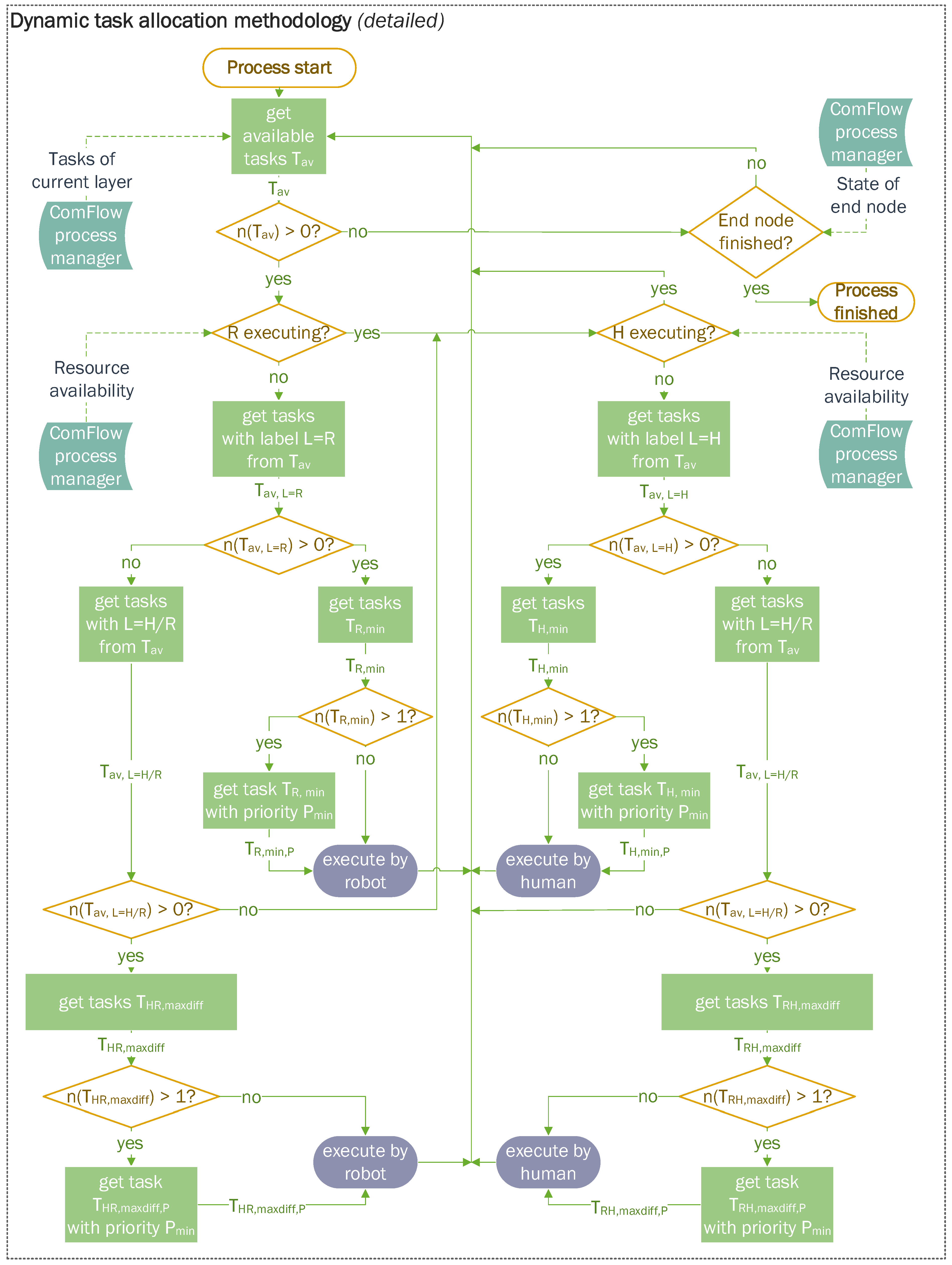
Figure A2 shows the detailed version of the flowchart of the proposed methodology for dynamic task allocation. The simplified version can be found in Figure 7.
Figure A2. Detailed version of the flowchart of the proposed methodology for dynamic task allocation. The iteration is continuous, i.e., after an assignment, the decision logic is immediately repeated by requesting currently available tasks again without waiting for the completion of the last assigned task.
Applsci 12 12645 g0a2

References

  1. Zanchettin, A.M.; Casalino, A.; Piroddi, L.; Rocco, P. Prediction of Human Activity Patterns for Human-Robot Collaborative Assembly Tasks. IEEE Trans. Ind. Inform. 2019, 15, 3934–3942. [Google Scholar] [CrossRef]
  2. Andolfatto, L.; Thiébaut, F.; Lartigue, C.; Douilly, M. Quality- and Cost-Driven Assembly Technique Selection and Geometrical Tolerance Allocation for Mechanical Structure Assembly. J. Manuf. Syst. 2014, 33, 103–115. [Google Scholar] [CrossRef] [Green Version]
  3. Spena, P.R.; Holzner, P.; Rauch, E.; Vidoni, R.; Matt, D.T. Requirements for the Design of Flexible and Changeable Manufacturing and Assembly Systems: A SME-Survey. Procedia CIRP 2016, 41, 207–212. [Google Scholar] [CrossRef]
  4. Fast-Berglund, Å.; Palmkvist, F.; Nyqvist, P.; Ekered, S.; Åkerman, M. Evaluating Cobots for Final Assembly. Procedia CIRP 2016, 44, 175–180. [Google Scholar] [CrossRef] [Green Version]
  5. Scholz-Reiter, B.; Freitag, M. Autonomous Processes in Assembly Systems. CIRP Ann. 2007, 56, 712–729. [Google Scholar] [CrossRef] [Green Version]
  6. ElMaraghy, H.; ElMaraghy, W. Smart Adaptable Assembly Systems. Procedia CIRP 2016, 44, 4–13. [Google Scholar] [CrossRef] [Green Version]
  7. Antonelli, D.; Astanin, S.; Bruno, G. Applicability of Human-Robot Collaboration to Small Batch Production. In IFIP Advances in Information and Communication Technology; Springer New York LLC: Torino, Italy, 2017; Volume 480, pp. 24–32. [Google Scholar] [CrossRef] [Green Version]
  8. Gaede, C.; Ranz, F.; Hummel, V.; Echelmeyer, W. A Study on Challenges in the Implementation of Human-Robot Collaboration. J. Eng. Manag. Oper. 2018, 1, 29–39, ISBN 978-3-643-99768-5. [Google Scholar]
  9. Lorenz, M.; Rüßmann, M.; Strack, R.; Lueth, K.L.; Bolle, M. Man and Machine in Industry 4.0: How will Technology Transform the Industrial Workforce Through 2025?. Bost. Consult. Group 2015. Available online: https://www.bcg.com/de-de/publications/2015/technology-business-transformation-engineered-products-infrastructure-man-machine-industry-4 (accessed on 6 December 2019).
  10. Müller, R.; Franke, J.; Henrich, D.; Kuhlenkötter, B.; Raatz, A.; Verl, A. Handbuch Mensch-Roboter-Kollaboration; Müller, R., Franke, J., Henrich, D., Kuhlenkötter, B., Raatz, A., Verl, A., Eds.; Carl Hanser Verlag GmbH & Co. KG: München, Germany, 2019; ISBN 978-3-446-45016-5. [Google Scholar] [CrossRef]
  11. Leng, J.; Sha, W.; Wang, B.; Zheng, P.; Zhuang, C.; Liu, Q.; Wuest, T.; Mourtzis, D.; Wang, L. Industry 5.0: Prospect and Retrospect. J. Manuf. Syst. 2022, 65, 279–295. [Google Scholar] [CrossRef]
  12. Romero, D.; Stahre, J. Towards the Resilient Operator 5.0: The Future of Work in Smart Resilient Manufacturing Systems. Procedia CIRP 2021, 104, 1089–1094. [Google Scholar] [CrossRef]
  13. Matheson, E.; Minto, R.; Zampieri, E.G.G.; Faccio, M.; Rosati, G. Human-Robot Collaboration in Manufacturing Applications: A Review. Robotics 2019, 8, 100. [Google Scholar] [CrossRef] [Green Version]
  14. Hold, P.; Ranz, F.; Sihn, W.; Hummel, V. Planning Operator Support in Cyber-Physical Assembly Systems. IFAC-PapersOnLine 2016, 49, 60–65. [Google Scholar] [CrossRef]
  15. Petzoldt, C.; Keiser, D.; Beinke, T.; Freitag, M. Functionalities and Implementation of Future Informational Assistance Systems for Manual Assembly. In Subject-Oriented Business Process Management. The Digital Workplace—Nucleus of Transformation. Proc. of S-BPM ONE 2020; Freitag, M., Kinra, A., Kotzab, H., Kreowski, H.J., Thoben, K.D., Eds.; Springer: Cham, Switzerland, 2020; Volume 1278, pp. 88–109. ISBN 978-3-030-64350-8. [Google Scholar] [CrossRef]
  16. Mark, B.G.; Rauch, E.; Matt, D.T. Worker Assistance Systems in Manufacturing: A Review of the State of the Art and Future Directions. J. Manuf. Syst. 2021, 59, 228–250. [Google Scholar] [CrossRef]
  17. Markets and Markets. Research Collaborative Robot Market Size, Growth, Trend and Forecast to 2025. Available online: https://www.marketsandmarkets.com/Market-Reports/collaborative-robot-market-194541294.html (accessed on 25 March 2020).
  18. Bauer, W.; Bender, M.; Braun, M.; Rally, P.; Scholtz, O. Lightweight Robots in Manual Assembly—Best to Start Simply! Examining Companies’ Initial Experiences with Lightweight Robots; Fraunhofer Institute for Industrial Engineering IAO: Stuttgart, Germany, 2016. [Google Scholar]
  19. Fast-Berglund, Å.; Romero, D. Strategies for Implementing Collaborative Robot Applications for the Operator 4.0. In IFIP Advances in Information and Communication Technology; Springer New York LLC: New York, NY, USA, 2019; Volume 566, pp. 682–689. [Google Scholar] [CrossRef]
  20. Michalos, G.; Karagiannis, P.; Dimitropoulos, N.; Andronas, D.; Makris, S. Human Robot Collaboration in Industrial Environments. In Intelligent Systems, Control and Automation: Science and Engineering; Springer Science and Business Media B.V.: Berlin/Heidelberg, Germany, 2022; Volume 81, pp. 17–39. [Google Scholar] [CrossRef]
  21. Statistisches Bundesamt. Industrie 4.0: Roboter in 16% Der Unternehmen Im Verarbeitenden Gewerbe; Statistisches Bundesamt: Wiesbaden, Germany, 2018. [Google Scholar]
  22. Schnell, M.; Holm, M. Challenges for Manufacturing SMEs in the Introduction of Collaborative Robots. In Proceedings of the SPS 2022: Proceedings of the 10th Swedish Production Symposium, Skövde, Sweden, 26–29 April 2022; pp. 173–183. [Google Scholar] [CrossRef]
  23. Kildal, J.; Tellaeche, A.; Fernández, I.; Maurtua, I. Potential Users’ Key Concerns and Expectations for the Adoption of Cobots. Procedia CIRP 2018, 72, 21–26. [Google Scholar] [CrossRef]
  24. Ranz, F.; Hummel, V.; Sihn, W. Capability-Based Task Allocation in Human-Robot Collaboration. Procedia Manuf. 2017, 9, 182–189. [Google Scholar] [CrossRef]
  25. Darvish, K.; Bruno, B.; Simetti, E.; Mastrogiovanni, F.; Casalino, G. Interleaved Online Task Planning, Simulation, Task Allocation and Motion Control for Flexible Human-Robot Cooperation. In Proceedings of the 2018 27th IEEE International Symposium on Robot and Human Interactive Communication (RO-MAN), Nanjing, China, 27–31 August 2018; pp. 58–65. [Google Scholar] [CrossRef]
  26. Gualtieri, L.; Rauch, E.; Vidoni, R. Human-Robot Activity Allocation Algorithm for the Redesign of Manual Assembly Systems into Human-Robot Collaborative Assembly. Int. J. Comput. Integr. Manuf. 2022, 1–26. [Google Scholar] [CrossRef]
  27. Müller, R.; Vette, M.; Mailahn, O. Process-Oriented Task Assignment for Assembly Processes with Human-Robot Interaction. Procedia CIRP 2016, 44, 210–215. [Google Scholar] [CrossRef]
  28. Bughin, J.; Hazan, E.; Lund, S.; Dahlström, P.; Wiesinger, A.; Subramaniam, A. Skill Shift: Automation and the Future of the Workforce. McKinsey Glob. Inst. 2018, 1, 3–84. [Google Scholar]
  29. Villani, V.; Pini, F.; Leali, F.; Secchi, C. Survey on Human–Robot Collaboration in Industrial Settings: Safety, Intuitive Interfaces and Applications. Mechatronics 2018, 55, 248–266. [Google Scholar] [CrossRef]
  30. Schmidbauer, C.; Schlund, S.; Ionescu, T.B.; Hader, B. Adaptive Task Sharing in Human-Robot Interaction in Assembly. In Proceedings of the IEEE International Conference on Industrial Engineering and Engineering Management (IEEM), Singapore, 14–17 December 2020; pp. 546–550. [Google Scholar] [CrossRef]
  31. Kopp, T.; Baumgartner, M.; Kinkel, S. Success Factors for Introducing Industrial Human-Robot Interaction in Practice: An Empirically Driven Framework. Int. J. Adv. Manuf. Technol. 2020, 112, 685–704. [Google Scholar] [CrossRef]
  32. Kumar, S.; Savur, C.; Sahin, F. Survey of Human-Robot Collaboration in Industrial Settings: Awareness, Intelligence, and Compliance. IEEE Trans. Syst. Man Cybern. Syst. 2021, 51, 280–297. [Google Scholar] [CrossRef]
  33. Kopp, T.; Schäfer, A.; Kinkel, S. Kollaborierende Oder Kollaborationsfähige Roboter?—Welche Rolle Spielt Die Mensch-Roboter-Kollaboration in Der Praxis? Ind. 4.0 Manag. 2020, 36, 19–23. [Google Scholar] [CrossRef]
  34. Petzoldt, C.; Keiser, D.; Siesenis, H.; Beinke, T.; Freitag, M. Ermittlung Und Bewertung von Einsatzpotentialen Der Mensch-Roboter-Kollaboration—Methodisches Vorgehensmodell Für Die Industrielle Montage. Zeitschrift für wirtschaftlichen Fabrikbetr. 2021, 116, 8–15. [Google Scholar] [CrossRef]
  35. Malik, A.A.; Bilberg, A. Complexity-Based Task Allocation in Human-Robot Collaborative Assembly. Ind. Robot Int. J. Robot. Res. Appl. 2019, 46, 471–480. [Google Scholar] [CrossRef]
  36. Liau, Y.Y.; Ryu, K. Genetic Algorithm-Based Task Allocation in Multiple Modes of Human–Robot Collaboration Systems with Two Cobots. Int. J. Adv. Manuf. Technol. 2022, 119, 7291–7309. [Google Scholar] [CrossRef]
  37. Lee, M.L.; Behdad, S.; Liang, X.; Zheng, M. Task Allocation and Planning for Product Disassembly with Human–Robot Collaboration. Robot. Comput. Integr. Manuf. 2022, 76, 102306. [Google Scholar] [CrossRef]
  38. Bänziger, T.; Kunz, A.; Wegener, K. Optimizing Human–Robot Task Allocation Using a Simulation Tool Based on Standardized Work Descriptions. J. Intell. Manuf. 2018, 31, 1635–1648. [Google Scholar] [CrossRef]
  39. El Makrini, I.; Merckaert, K.; De Winter, J.; Lefeber, D.; Vanderborght, B.; DeWinter, J.; Lefeber, D.; Vanderborght, B. Task Allocation for Improved Ergonomics in Human-Robot Collaborative Assembly. Interact. Stud. Soc. Behav. Commun. Biol. Artif. Syst. 2019, 20, 102–133. [Google Scholar] [CrossRef]
  40. Pupa, A.; Secchi, C. A Safety-Aware Architecture for Task Scheduling and Execution for Human-Robot Collaboration. In Proceedings of the IEEE International Conference on Intelligent Robots and Systems, Prague, Czech Republic, 27 September 2021–1 October 2021; Institute of Electrical and Electronics Engineers Inc.: Piscataway, NJ, USA, 2021; pp. 1895–1902. [Google Scholar] [CrossRef]
  41. Heydaryan, S.; Bedolla, J.S.; Belingardi, G. Safety Design and Development of a Human-Robot Collaboration Assembly Process in the Automotive Industry. Appl. Sci. 2018, 8, 344. [Google Scholar] [CrossRef] [Green Version]
  42. Rahman, S.M.M.; Wang, Y. Mutual Trust-Based Subtask Allocation for Human–Robot Collaboration in Flexible Lightweight Assembly in Manufacturing. Mechatronics 2018, 54, 94–109. [Google Scholar] [CrossRef]
  43. Messeri, C.; Bicchi, A.; Zanchettin, A.M.; Rocco, P. A Dynamic Task Allocation Strategy to Mitigate the Human Physical Fatigue in Collaborative Robotics. IEEE Robot. Autom. Lett. 2022, 7, 2178–2185. [Google Scholar] [CrossRef]
  44. Antonelli, D.; Bruno, G. Dynamic Distribution of Assembly Tasks in a Collaborative Workcell of Humans and Robots. FME Trans. 2019, 47, 723–730. [Google Scholar] [CrossRef] [Green Version]
  45. Hevner, A.R.; March, S.T.; Park, J.; Ram, S. Design Science in Information Systems Research. Manag. Inf. Syst. Q. MIS Q. 2004, 28, 75–105. [Google Scholar] [CrossRef] [Green Version]
  46. Peffers, K.; Tuunanen, T.; Rothenberger, M.A.; Chatterjee, S. A Design Science Research Methodology for Information Systems Research. J. Manag. Inf. Syst. 2007, 24, 45–77. [Google Scholar] [CrossRef]
  47. Niermann, D.; Petzoldt, C.; Dörnbach, T.; Isken, M.; Freitag, M. Towards a Novel Software Framework for the Intuitive Generation of Process Flows for Multiple Robotic Systems. Procedia CIRP 2022, 107, 137–142. [Google Scholar] [CrossRef]
  48. Petzoldt, C.; Panter, L.; Niermann, D.; Vur, B.; Freitag, M.; Doernbach, T.; Isken, M.; Sharma, A. Intuitive Interaktionsschnittstelle Für Technische Logistiksysteme—Konfiguration Und Überwachung von Prozessabläufen Mittels Multimodaler Mensch-Technik-Interaktion Und Digitalem Zwilling. Ind. 4.0 Manag. 2021, 37, 42–46. [Google Scholar]
  49. Konold, P.; Reger, H. Praxis Der Montagetechnik, 2nd ed.; Springer Fachmedien: Wiesbaden, Germany, 2003; ISBN 9783663016106. [Google Scholar] [CrossRef]
  50. Schröter, D. Entwicklung Einer Methodik Zur Planung von Arbeitssystemen in Mensch-Roboter-Kooperation; Universität Stuttgart: Stuttgart, Germany, 2018. [Google Scholar] [CrossRef]
  51. Beumelburg, K. Fähigkeitsorientierte Montageablaufplanung in Der Direkten Mensch-Roboter-Kooperation (Engl. Skill-Oriented Assembly Sequence Planning for the Direct Man-Robot-Cooperation); Jost Jetter Verlag: Heimsheim, Germany, 2005; ISBN 393694752X. [Google Scholar] [CrossRef]
  52. Chacón, A.; Ponsa, P.; Angulo, C. Usability Study through a Human-Robot Collaborative Workspace Experience. Designs 2021, 5, 35. [Google Scholar] [CrossRef]
  53. DIN EN ISO 9241-11; Ergonomics of Human-System Interaction—Part 11: Usability: Definitions and Concepts (ISO 9241-11:2018). 2018. Available online: https://www.iso.org/standard/63500.html (accessed on 25 May 2022).
  54. Hoffman, G. Evaluating Fluency in Human-Robot Collaboration. IEEE Trans. Hum. Mach. Syst. 2019, 49, 209–218. [Google Scholar] [CrossRef]
  55. Gervasi, R.; Mastrogiacomo, L.; Franceschini, F. A Conceptual Framework to Evaluate Human-Robot Collaboration. Int. J. Adv. Manuf. Technol. 2020, 108, 841–865. [Google Scholar] [CrossRef]
  56. Hart, S.G.; Staveland, L.E. Development of NASA-TLX (Task Load Index): Results of Empirical and Theoretical Research. Adv. Psychol. 1988, 52, 139–183. [Google Scholar] [CrossRef]
  57. Hart, S.G. NASA-Task Load Index (NASA-TLX); 20 Years Later. Proc. Hum. Factors Ergon. Soc. 2006, 50, 904–908. [Google Scholar] [CrossRef] [Green Version]
  58. Tausch, A.; Kluge, A. The Best Task Allocation Process Is to Decide on One’s Own: Effects of the Allocation Agent in Human–Robot Interaction on Perceived Work Characteristics and Satisfaction. Cogn. Technol. Work 2020, 24, 39–55. [Google Scholar] [CrossRef]
  59. Charalambous, G.; Fletcher, S.; Webb, P. The Development of a Scale to Evaluate Trust in Industrial Human-Robot Collaboration. Int. J. Soc. Robot. 2016, 8, 193–209. [Google Scholar] [CrossRef]
  60. Brooke, J. SUS: A “Quick and Dirty” Usability Scale. In Usability Evaluation in Industry; Jordan, P.W., Thomas, B., McClelland, I.L., Weerdmeester, B., Eds.; CRC Press: Boca Raton, FL, USA, 1996; pp. 207–212. [Google Scholar] [CrossRef]
  61. Lewis, J.R. The System Usability Scale: Past, Present, and Future. Int. J. Hum.–Comput. Interact. 2018, 34, 577–590. [Google Scholar] [CrossRef]
  62. Marvel, J.A.; Bagchi, S.; Zimmerman, M.; Antonishek, B. Towards Effective Interface Designs for Collaborative HRI in Manufacturing: Metrics and Measures. ACM Trans. Hum. Robot Interact. 2020, 9, 1–55. [Google Scholar] [CrossRef]
  63. Knight, S.A.; Burn, J. Developing a Framework for Assessing Information Quality on the World Wide Web. Inf. Sci. 2005, 8, 159–172. [Google Scholar] [CrossRef] [Green Version]
  64. Franke, T.; Attig, C.; Wessel, D. Assessing Affinity for Technology Interaction—The Affinity for Technology Assessing Affinity for Technology Interaction (ATI). 2017; Unpublished. [Google Scholar] [CrossRef]
  65. Prabaswari, A.D.; Basumerda, C.; Utomo, B.W. The Mental Workload Analysis of Staff in Study Program of Private Educational Organization. In Proceedings of the IOP Conference Series: Materials Science and Engineering; Institute of Physics Publishing, Makasar, Indonesia, 27–29 November 2018; Volume 528, p. 012018. [Google Scholar] [CrossRef]
  66. Bruno, G.; Antonelli, D. Dynamic Task Classification and Assignment for the Management of Human-Robot Collaborative Teams in Workcells. Int. J. Adv. Manuf. Technol. 2018, 98, 2415–2427. [Google Scholar] [CrossRef]
  67. Tsarouchi, P.; Matthaiakis, A.S.S.; Makris, S.; Chryssolouris, G. On a Human-Robot Collaboration in an Assembly Cell. Int. J. Comput. Integr. Manuf. 2016, 30, 580–589. [Google Scholar] [CrossRef] [Green Version]
  68. Chen, F.; Sekiyama, K.; Cannella, F.; Fukuda, T. Optimal Subtask Allocation for Human and Robot Collaboration within Hybrid Assembly System. IEEE Trans. Autom. Sci. Eng. 2014, 11, 1065–1075. [Google Scholar] [CrossRef]
  69. Johannsmeier, L.; Haddadin, S. A Hierarchical Human-Robot Interaction-Planning Framework for Task Allocation in Collaborative Industrial Assembly Processes. IEEE Robot. Autom. Lett. 2017, 2, 41–48. [Google Scholar] [CrossRef]
  70. Smyk, A. The System Usability Scale & How It’s Used in UX. 2020. Available online: https://xd.adobe.com/ideas/process/user-testing/sus-system-usability-scale-ux/ (accessed on 4 November 2022).
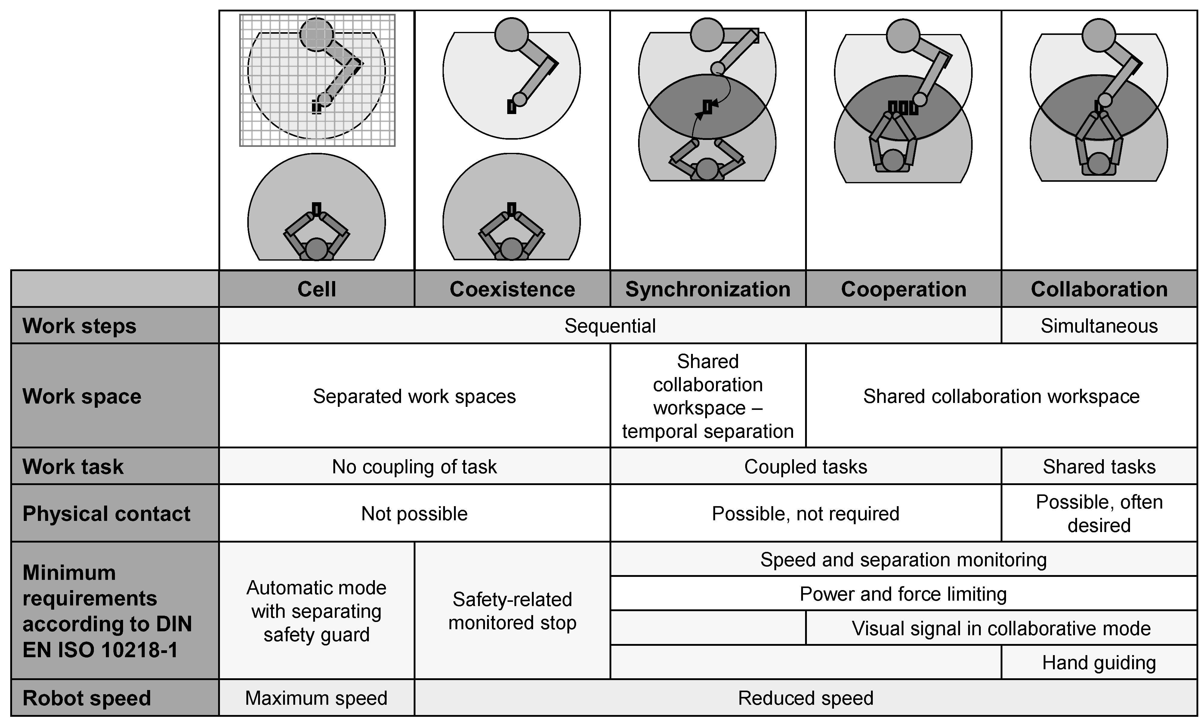
Figure 1. Overview of the levels of cooperation between humans and robots and their characteristics (according to [18,33]; translated from [34]).
Applsci 12 12645 g001
Figure 2. Research approach for the study following the Design Science Research procedure model from [46].
Applsci 12 12645 g002
Figure 3. System architecture of the software framework ComFlow for block-based no-code programming with integration of the task allocation module and the specific hardware setup within this article for enabling human–robot collaborative assembly (extended and adapted based on [47]).
Applsci 12 12645 g003
Figure 4. Process for implementation and execution of assembly processes with the software framework and illustration of the conceptual user interfaces.
Applsci 12 12645 g004
Figure 5. Conceptual representation of function blocks, which include sub-processes for the execution of the tasks by humans or robots (HRC nodes).
Applsci 12 12645 g005
Figure 7. Flowchart of the proposed methodology for dynamic task allocation (simplified version). The iteration is continuous, i.e., after an assignment, the decision logic is immediately repeated by requesting currently available tasks again without waiting for the completion of the last assigned task.
Applsci 12 12645 g007
Figure 8. Implementation of sub-processes and HRC nodes in user interface: creation of the sub-process with sequences for both human and robot.
Applsci 12 12645 g008
Figure 9. Implementation of sub-processes and HRC nodes in user interface: Selection of the saved HRC sub-process for the creation of the overall assembly process.
Applsci 12 12645 g009
Figure 10. Web-based user interface for process creation and process execution: process flow editor for creation of the assembly process.
Applsci 12 12645 g010
Figure 11. Web-based user interface for process creation and process execution: process flow viewer with integrated worker instruction system for the execution of the assembly process.
Applsci 12 12645 g011
Figure 12. Experimental setup of the collaborative assembly station for the study.
Applsci 12 12645 g012
Figure 13. Assembly component for user study: (a) exploded view; (b) assembled real components; (c) assembly precedence graph for one assembly component.
Applsci 12 12645 g013aApplsci 12 12645 g013b
Figure 14. Assembly sequences for the implemented task allocation modes in human-robot collaboration.
Applsci 12 12645 g014
Figure 15. Dependent and independent variables of the evaluation study.
Applsci 12 12645 g015
Figure 16. Procedure of the user study.
Applsci 12 12645 g016
Figure 17. Exemplary Gantt charts for assembly process in different task allocation modes: (a) assembly of one component with 90 s human delay; (b) assembly of three components with 90 s human delay.
Applsci 12 12645 g017
Figure 18. Comparison of task allocation modes depending on the number of assembled components.
Applsci 12 12645 g018
Figure 19. Comparison of task allocation modes depending on duration of human task delay for assembly of three components.
Applsci 12 12645 g019
Figure 20. HRC performance KPI for the different task allocation modes depending on the duration of delay for the assembly of three components.
Applsci 12 12645 g020
Figure 21. Detailed assessment of fluency and satisfaction in spider diagrams. (a) Fluency assessment. Questions with reversed scales were worded positively for illustration in spider diagram and the point value was reversed. (b) Satisfaction assessment.
Applsci 12 12645 g021
Figure 22. Subjects’ ranking of preferred task allocation mode.
Applsci 12 12645 g022
Table 1. Key challenges in human–robot collaboration (HRC) identified in the literature and grouped into three categories: safety, planning, and technology. The original categories of challenges proposed by the respective references are indicated in italics. The challenge of task allocation is highlighted in bold in the referenced studies.
Category[8,24] 1[29][30][22] 2
Safety
  • Individual risk assessment
  • Application of norms in practice
  • Approval through inspecting authority
Safe interaction
  • Safety standards
  • Collaborative operating modes
  • Individual risk assessment
  • Safety certifications are costly and time-consuming
Safety
  • Application of norms in practice
  • Individual risk assessment
  • Human’s trust in robot
  • Certification
Planning
  • Identification of suitable workstations
  • Workplace design
  • Task allocation among human and robot
  • Quantification of effect on flexibility
  • Quantification of effect on productivity
Intuitive interfaces
  • Programming approaches
  • Input modes
Design methods
  • Task planning and task allocation
  • Lack of professional expertise and robot programmers in SMEs
  • Fragmentation of human tasks
Performance
  • Limited speed
  • Lack of quality checks
Strategy
  • Cost-effectiveness
  • Identification of suitable workstations
  • Task allocation among humans and robots
Involvement and training
  • Need for training and education of workers
  • Involvement of operators
  • Fear of being replaced
Technology
  • -
Design methods
  • Control laws
  • Sensors
  • Handling of unforeseen errors is costly
Smart technology
  • Intelligent solutions for quality control
  • Flexible robot movement between different workstations
1 Extract of the top eight challenges for implementing HRC according to robot manufacturers. 2 Focus on challenges reported from industry.
Table 2. Overview of investigated variables, utilized metrics, and the approach for data collection.
Evaluation AspectVariableMetricsSymbolData Collection
EffectivenessProcess effectivenessTask completion rate TCR notes during study
Number of errors n err notes during study
EfficiencyProcess efficiencyProcess time t process process data logging
HRC performance efficiencyNumber of human tasks n H process data logging
Number of robot tasks n R process data logging
Human wait time t H ,   wait process data logging
Robot wait time t R , wait process data logging
Concurrent activity time t HR , concurrent process data logging
User satisfaction (human factors)WorkloadNASA Raw TLX RTLX questionnaire
Fluency and
satisfaction
Fluency score Fluency questionnaire
Satisfaction score Satisfaction questionnaire
User preferencePreferred task allocation mode-questionnaire
General system
assessment
System usability scale score SUS questionnaire
Trust evaluation score Trust questionnaire
Quality of provided information Q info questionnaire
Qualitative feedback-free text input
Suggestions for improvement-free text input
Table 3. Demographic and experience data for the subjects in the user study: (a) gender information; (b) age information; (c) vocational education information; (d) previous experience in manual assembly, use of assistance systems in industrial contexts, and programming or working with collaborative robots; (e) technical affinity information.
(a)
Gender
(b)
Age
(c)
Vocational Education
(d)
Experience
(e)
Technical Affinity
F25%20–2440%Academic50%Assembly60% 1ATI score
M75%25–2940%Undergraduate50%Assistance systems40% 14.74 ± 0.68
N/D−/−30–3410% Collaborative robots25% 1
35–4910%
1 Subjects with response of 4 or higher on 5-level Likert scale.
Table 4. Overview of mean process times per task allocation mode and duration of the delay. The task allocation mode with minimum process time is highlighted in bold for each setting.
Process Time in s
Task Allocation ModeComponentsDelay = 0 sDelay = 30 sDelay = 60 sDelay = 90 s
Manual 1192.6 ± 55.4254.0 ± 6.7251.4 ± 49.2279.6 ± 50.2
Static 153.0 ± 7.3183.2 ± 31.0209.6 ± 9.9233.6 ± 17.4
Dynamic152.0 ± 37.7191.0 ± 18.6208.2 ± 3.5241.6 ± 24.8
Static (asymmetric)3431.6 ± 78.1442.8 ± 73.5477.0 ±55.5510.8 ± 60.6
Static 452.8 ± 108.6484.0 ± 72.7427.6 ± 25.9467.2 ± 63.5
Dynamic363.4 ± 69.0422.2 ± 57.5410.6 ± 28.8447.6 ± 35.6
Table 5. Assessment results for workload, fluency, and satisfaction for the different task allocation modes.
DataManualStatic (Asymmetric)StaticDynamic
NASA RTLX score
(adjective rating)
17.7 ± 7.1
(medium workload)
12.5 ± 2.6
(medium workload)
11.3 ± 4.1
(medium workload)
18.5 ± 7.6
(medium workload)
Fluency score +-3.5 ± 0.9 1,23.5 ± 0.8 1,23.7 ± 0.8 1,2
Satisfaction score +-3.6 ± 0.6 13.9 ± 0.4 14.4 ± 0.2 1
1 Mean response on 5-level Likert scale. 2 The point value of questions with a reversed scale was reversed for uniformity and consistency of the score. + Higher value indicates better score. Lower value indicates better score.
Table 6. General system assessment: (a) system usability; (b) quality of provided information; (c) subjects’ readiness for permanent system usage; (d) trust in robot.
(a)
Usability
(b)
Quality of Provided Information
(c)
Permanent Use of System 2
(d)
Trust
SUS score79.4 ± 12.5Correctness and
completeness
4.5 ± 0.9 1Yes85 %Trust score43.3 ± 4.1
Acceptability rating AcceptableRelevance and timing4.25 ± 0.8 1No5 %
Adjective ratingGoodUnderstandability and comprehensibility4.2 ± 1.0 1Not sure10 %
Easy and quick
information extraction
3.5 ± 1.3 1
1 Mean response on 5-level Likert scale. 2 Subjects’ response to question “Would you use the system permanently?”.
Publisher’s Note: MDPI stays neutral with regard to jurisdictional claims in published maps and institutional affiliations.