Article

A Study on the Efficiency in the Energy Harvesting Device Using Resonance of Pendulum

1
Department of Automotive Engineering, Dong-eui University, Busan 47340, Republic of Korea
2
Department of Mechanical Engineering, Dong-eui University, Busan 47340, Republic of Korea
*
Author to whom correspondence should be addressed.
Appl. Sci. 2022, 12(22), 11862; https://doi.org/10.3390/app122211862
Submission received: 17 October 2022 / Revised: 16 November 2022 / Accepted: 17 November 2022 / Published: 21 November 2022

Abstract

:
Recently, increased public interest in pollution caused by fossil fuels has prompted studies on various renewable energy sources. As it is important to ensure power generation efficiency in energy harvesting, research in this area continues. Therefore, this paper presents the results of a numerical analysis to calculate the efficiency of an energy harvesting generator that uses pendulum resonance. The Lagrange equation was used to derive the numerical model of the pendulum, which in turn was used to derive the angle of power generation and time required to reach this angle. The power generation efficiency was derived by calculating the input and output work using the power generation angle and time obtained from the numerical model. In addition, the effect of design variables, such as the mass of the pendulum, the length of the pendulum, and angle at which power generation starts, on the efficiency is considered by presenting an efficiency map. The efficiency map presented in this study is expected to be an important reference for designing highly efficient energy harvesting devices using pendulum resonance.

1. Introduction

Recently, various countries have been creating and enforcing energy-related regulations to reduce environmental pollution caused by fossil fuels [1,2,3]. In addition, there is increasing concern regarding the depletion of fossil fuels, and research is underway on various renewable energy sources to replace them. Energy harvesting converts natural energy into electrical energy. Among the various energy harvesting methods, the use of a mechanical vibration component is a typical power generation method [4,5,6,7,8]. However, energy harvesting is mainly used for low-power generation because of irregular power generation conditions such as wind or waves [9,10].
To solve these problems, many studies have been conducted to utilize resonance phenomena in energy harvesting. A representative case study is the wingless wind turbine presented by Yanez et al. [11] The generator is in the form of a cantilever beam fixed vertically to the floor, and it harnesses the force of the turbulence generated by natural wind passing through the pillars. The energy from the force of the turbulent flow generated at this time is dispersed over a wide low frequency band. Permanent magnets were installed on both sides of the outer wall and a nonlinear resonance frequency model was used to generate power over the widest possible frequency band. In another study using pendulum resonance, Marszal et al. [12] proposed a pendulum resonance generator model in which the frequency of an artificial pool for collecting wave energy matches the resonance frequency of the pendulum. Abohamer et al. [13] proposed a model in which a pendulum is installed on a rotating body and the rotational vibration component is used for power generation. In addition, Izadgoshasba et al. [14] presented an extremely low frequency generator model that collects the energy generated when a person moves using a double pendulum structure and used the motion of the pendulum for generation. Energy harvesting devices using high frequencies, such as radio frequency (RF), have been studied, not in low-frequency power generation environments such as wind or waves. Elwi et al. [15,16,17,18] researched a high-frequency broadband RF energy harvesting device using a metamaterial with resonant frequency. Abdulmjeed et al. [19] studied broadband planar antennas by using H-shaped Resonators (HSRs). Ghadeer et al. [20] reproduced an antenna structure that can utilize resonance from 3.5 GHz to 5 GHz by placing 3D MIMO nano-cells in an array structure.
Research on power generation using resonance has also been conducted out using piezoelectric elements or linear electromagnetic induction methods. Fan et al. [21] advanced the research on generating energy by attaching a piezoelectric element to the hanger structure. Bradai et al. [22] installed two permanent magnets facing the same pole, constructed a nonlinear resonance frequency model, and proceeded with research on generating energy through electromagnetic induction in the case-surrounding coil. Research has also been conducted to utilize the pendulum as a medium for power generation. Xu et al. [23] presented a generator model that utilizes the resonant frequency of the pendulum’s rotational motion by suspending the pendulum at the end of a cantilever beam. Wu et al. [24] presented a spring-type pendulum using a clip, and a power generation model with piezoelectric elements attached to each clip. Kecik [25] presented a model in which a vertically moving vibration absorber was installed on the main body and electricity was generated using magnets and coils at the ends of the vibration absorber.
The above studies presented various generator models using resonance, and defined forces used for resonance, such as turbulence owing to wind and wave force. In addition, various methods have been proposed for constructing a generator model using resonance, such as research using resonance for power generation through the mounting position of the piezoelectric element and a generator utilizing electromagnetic induction. However, although the resonance frequency has been determined and a method presented, the efficiency owing to the generator design variables of pendulum length and mass have not been considered. In addition, assuming a form of continuous power generation, the angle at which power generation starts has not determined, nor has the efficiency of the angle been considered. A generator using resonance has various design variables depending on the structure to induce resonance, and these design variables have a significant impact on the efficiency of the generator.
Therefore, this study used a generator with pendulum resonance to compare, the power generation efficiencies according to the pendulum mass, the pendulum length, and angle at which the pendulum starts to generate power. The device presented in this study uses a motor and generator (MG). When the motor applies torque, the pendulum starts to move, and after reaching a certain angle, the motor acts as a generator. Section 2 describes the analysis of the motion of the pendulum attached to the axis of the MG, which is based on the equation of motion with the pendulum rotation angle θ as a variable. Next, Section 3 presents the results, discussion, and a calculation on the time required for power generation to begin, which uses the rotation angle of the pendulum described in Section 2. Based on this, we derived an efficiency map that describes the changes in efficiency depending on the design variables.

2. Methods

For the analysis, this study used a system where a generator is attached to a rotating shaft to which a pendulum is connected. The diagram used for mathematical analysis is shown in Figure 1. The pendulum is assumed to move in the x, y plane and the gravitational acceleration is assumed to act in the -y direction.
Figure 1 shows a simple model for analyzing pendulum motion, where the MG is a motor and generator. When the MG acts as a motor, it supplies an excitation force to the pendulum. The MG can rotate with the same resonant frequency of the pendulum by a controller. For the energy source, pre-generators can utilize a variety of energy harvesting devices, such as piezoelectric or triboelectric from sources such as wind, vibration, and static electricity [26,27,28]. In Figure 1, l is the pendulum length, m is the pendulum mass, and M(t) is the excitation torque when the MG is a motor. When the pendulum stops without any movement, it is called the equilibrium position. The angle θ at which the pendulum moves can be derived by solving the equation of motion, and power generation is started when θ reaches a certain angle owing to the force. At this time, the electrical efficiency of the generator is a specific constant. However, as it is not considered in this study it is set to 1, and the losses such as the friction of the pendulum are ignored.
In this study, the equation of motion of the pendulum is derived using the Lagrange equation, and the equation of motion is derived using the definition from Lagrangian mechanics, which states that the difference between the kinetic energy and potential energy is the same as the general work applied from the outside. The position and velocity of the x and y coordinate axes shown in Figure 1 are expressed by length l and angle θ of the pendulum, respectively, and are used to derive the kinetic and potential energies of the system.
T = 1 2 m v 2 = 1 2 m ( ( l cos θ θ ˙ ) 2 + ( l sin θ θ ˙ ) 2 ) 2 = 1 2 m l 2 θ ˙ 2
U = m g Δ h = m g l ( 1 cos θ )
Equations (1) and (2) refer to the kinetic energy T and potential energy U of the system, respectively, and they are both functions of θ. By applying Equations (1) and (2) to the Lagrange equation, the equation of motion is derived as follows:
d d t T θ ˙ + T θ + U θ = m l 2 θ ¨ + m g l sin θ = M ( t )
In Equation (3), M(t) means the excitation torque that occurs when the MG operates as a motor, and the frequency of this torque is the same as the resonance frequency of the pendulum. The resonance frequency of the pendulum can be derived by assuming that there is no torque in Equation (3). Because the resonance frequency of a simple pendulum is ω n = g / l , the torque M(t) is expressed by:
M ( t ) = a l cos ( g l t )
In Equation (4), the excitation torque simulates the case in which there is an excitation force on the mass of the pendulum, a is the magnitude of the excitation force, and g is the gravity. The solution of the equation of motion θ obtained from Equations (3) and (4) is the same as:
θ ( t ) = a 2 m l ω n t sin ( ω n t )
Equation (5) describes the pendulum motion θ when the pendulum receives force M(t), as represented by Equation (4).

3. Results and Discussion

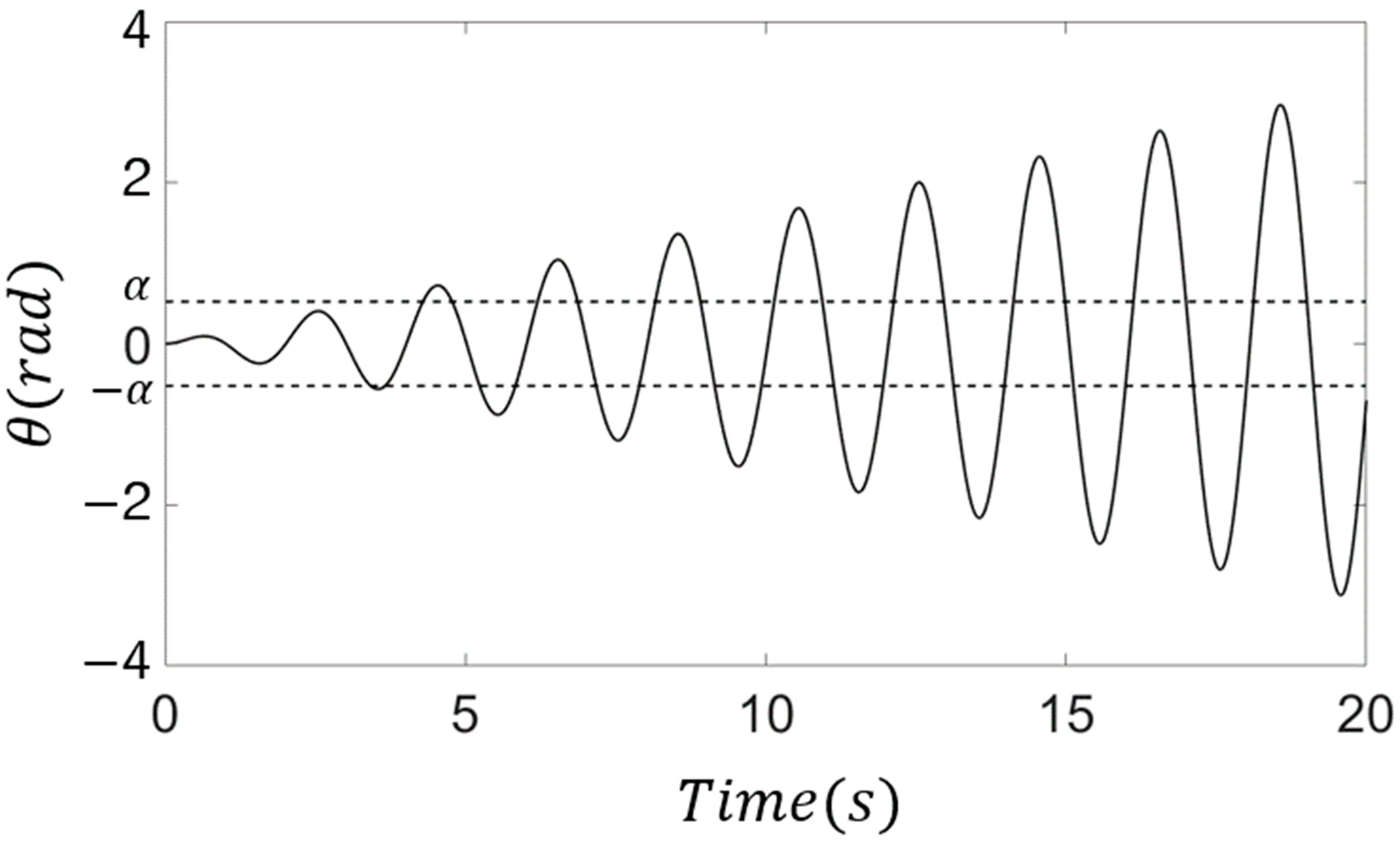
As explained in Section 2, the pendulum movement can be found using Equation (5). Applying a force with the same frequency as the pendulum’s resonant frequency causes the pendulum to diverge over time, which can be used to reach the angle for power generation. The solid line in Figure 2 is a graph representing the θ value of Equation (5), the horizontal axis represents time, the vertical axis represents the angle θ of the pendulum, and α is the angle at which power generation start. When the pendulum angle reaches angle α in the forward or reverse direction, power generation begin, and when the pendulum stops at the equilibrium position, the force is applied again to move the pendulum. To obtain the amount of work at this time, it is first necessary to determine the time it takes for the pendulum angle theta to reach the start angle of power generation. In Figure 2, where the solid and dotted line meet, the value of the horizontal axis can be obtained and derived. From Equation (5), the time taken for the pendulum to move to the angle for power generation is determined by the mass of the pendulum m, the length of pendulum l, and the power generation angle α.
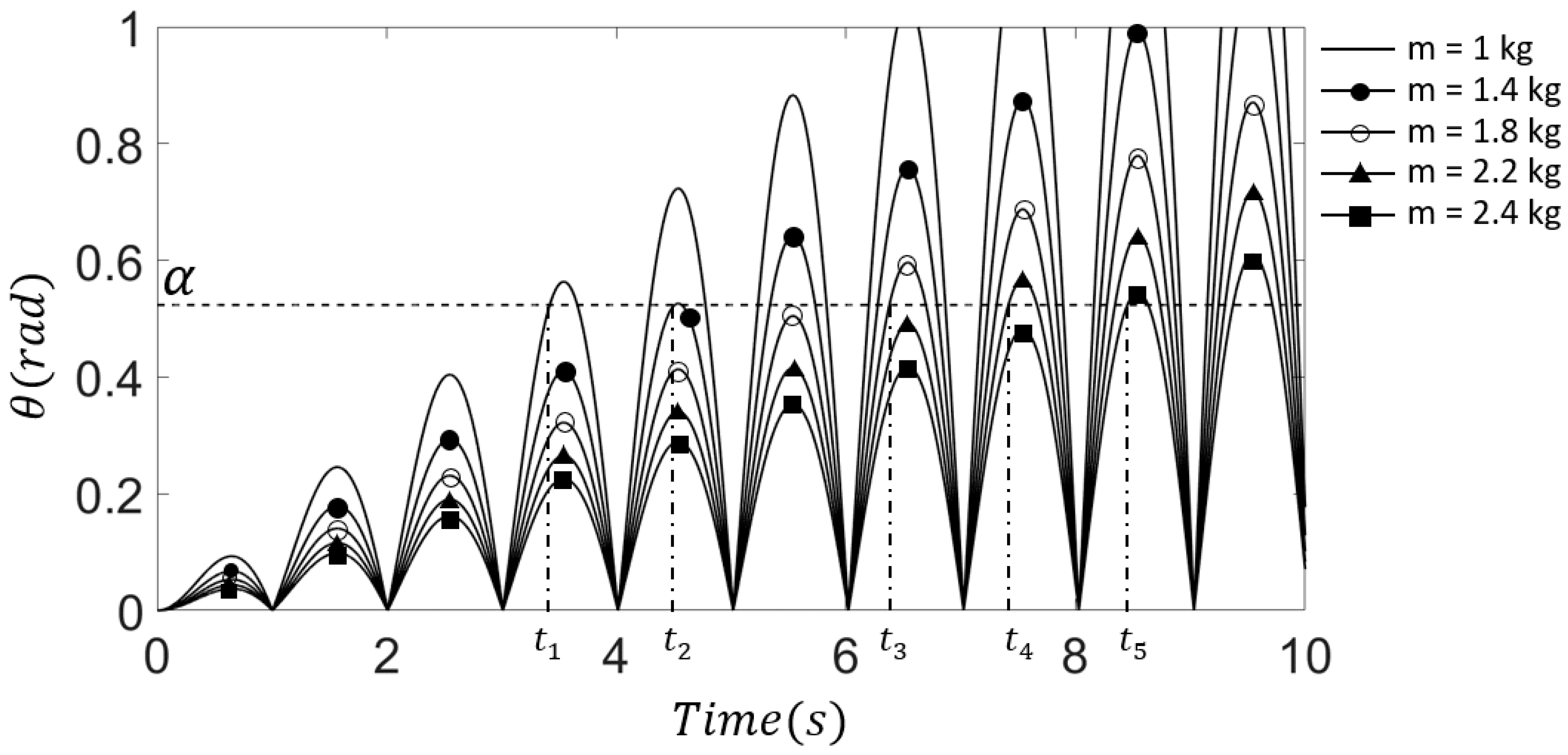
Figure 3 shows the displacement of the pendulum for the following masses: 1 kg, 1.4 kg, 1.8 kg, 2.2 kg, and 2.4 kg depicted using solid lines and symbols. In addition, the angle α at which power generation starts can be determined by the user. An arbitrary value π/6 was used in Figure 3. The power generation time ( t 1 to t 5 ) can be derived from the intersection of the solid line and the dotted lines. Table 1 lists the time required to reach the power generation angle for each mass.
Table 1 summarizes the power generation time according to the mass of the pendulum with π/6 determined by the power generation angle, which is Δ t = t n + 1 t n . Based on the time required to reach α, as listed in Table 1, it can be observed that as the mass increases, the time to reach the power generation angle also increases. From the Δ t values in Table 1, it can be confirmed that t n increases in intervals of approximately 1.05 s as the mass of the pendulum increases; however, the interval between 1.4 kg and 1.8 kg is 1.88 s. From this, it can be seen that T α does not change linearly as the mass increases, but there is a section in which it increases nonlinearly. A phenomenon in which the efficiency of the generator decreases occurs in such a nonlinear part, and the specific content of efficiency will be discussed in this section.
As described in the earlier, when determining the design parameters and deriving the time taken to reach the development angle, the amount of work performed by the MG until the pendulum starts to develop can be also determined.
W i n = 0 T a M ( t ) θ ˙ d t
Equation (6) derives the amount of work from the moment the pendulum receives the force at the equilibrium position to the end of the movement. Here, M(t) is the torque, T α is the time taken to start generation, θ ˙ is the speed of the pendulum. The forces are in the form of torque and are developed in response to clockwise ( ) and counterclockwise (+) bi-directional displacements. After removing the force, the pendulum will start generating electricity when it reaches a certain angle, and the potential energy of the pendulum is used to generate electricity. Therefore, the power generation of the pendulum is the same as the potential energy difference of the pendulum, which initiates the power generation and potential energy of the equilibrium position.
W o u t = Δ U = m g Δ h = m g l ( 1 cos θ )
Equation (7) represents the amount of change in potential energy, that is, the amount of power generated by potential energy, where m is the mass of the pendulum, l is the length of the pendulum, and g is the gravitational acceleration. The height difference between the angle at which the pendulum starts generating power and the equilibrium position is given by Δ h , and it corresponds to the difference in y-axis position between the power generation start position from the equilibrium position, as shown in Figure 2. The input and output work can be derived using a mathematical model of the pendulum which begins to develop when the displacement of the pendulum reaches a certain angle. Using this, the power generation efficiency corresponding to the pendulum mass m, pendulum length l, and power generation angle α can be derived.
Figure 4 shows the time required to reach the power generation angle according to the pendulum mass and length. It can be observed that the longer the length and the greater the mass of the pendulum, the longer it takes to reach the generating angle. In addition, the pendulum length was short, there was no significant difference in the time required for the different pendulum mass values to reach the power generation angle. Once the time to reach the power generation angle is determined, the input and output of the generator can be calculated using Equations (6) and (7), and the power generation efficiency can be defined as follows:
η = W o u t W i n
Equation (8) expresses the efficiency of the generator, Here, W i n is the amount of work input until the pendulum reaches the power generation angle derived from Equation (6), and W o u t is the power generation energy of the pendulum at the power generation angle derived from Equation (7). Using Equation (8), the efficiencies according to the length of the pendulum, mass of the pendulum, and angle of power generation can be obtained.
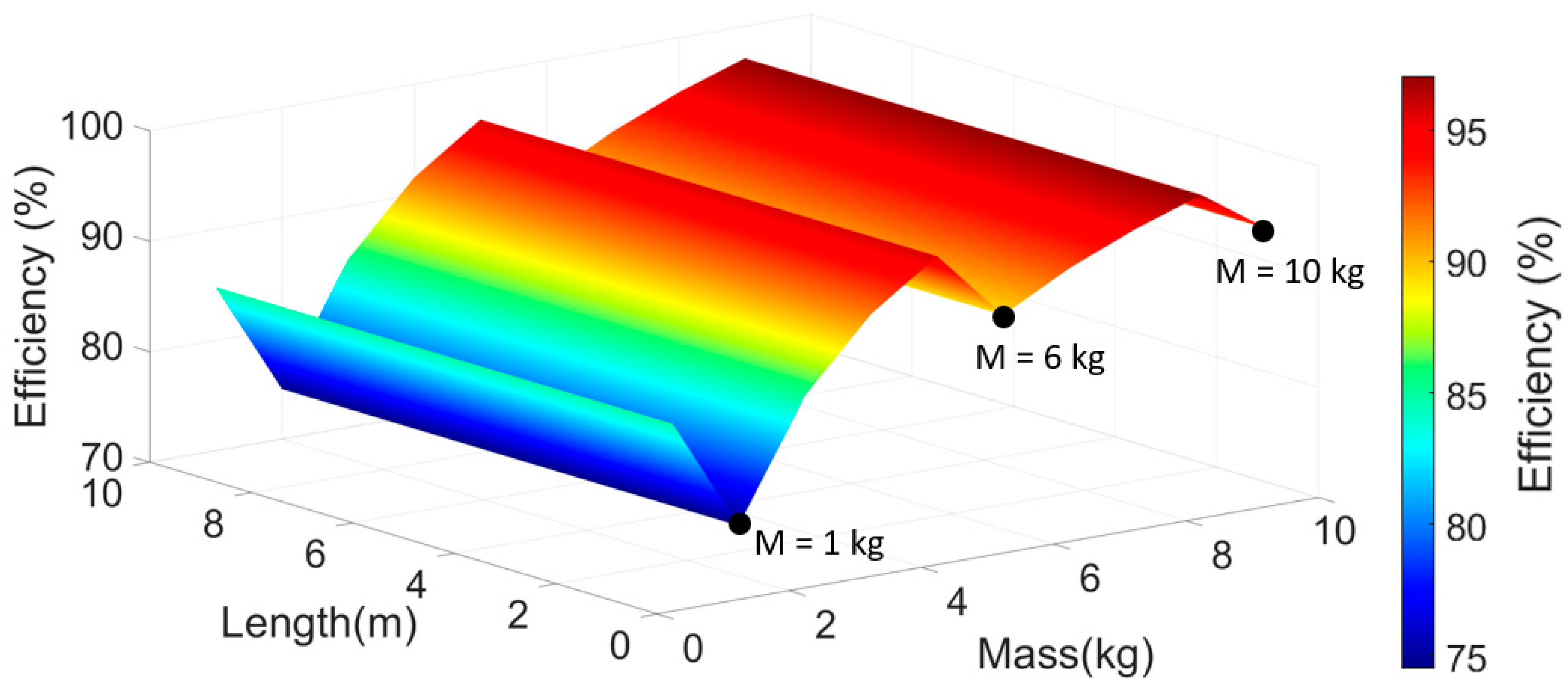
Figure 5 shows the power generation efficiency depending on the mass and length of the pendulum, where the power generation angle α was fixed at π/6. The efficiency tends to increase as the pendulum mass increases, but drops sharply at approximately 1 kg, 6 kg, and 10 kg. These are the points at which the time to reach the power generation angle mentioned in Figure 3 and Table 1 changes non-linearly. This can occur when fixing the generation angle and is a consideration in generator design. The pendulum length does not affect the efficiency, but only the period of the pendulum.
Figure 6 shows the dependence the efficiency on the length of the pendulum and power generation angle α, when the mass m of the pendulum was fixed at 1 kg. Figure 6 also shows that the efficiency does not change linearly with the generation angle. It can be seen that the generation efficiency is low at the generation angle α values of π/30, π/12, and 2 π/15. Interestingly, the length of the pendulum has no effect on the power generation efficiency, only on the period of the pendulum.
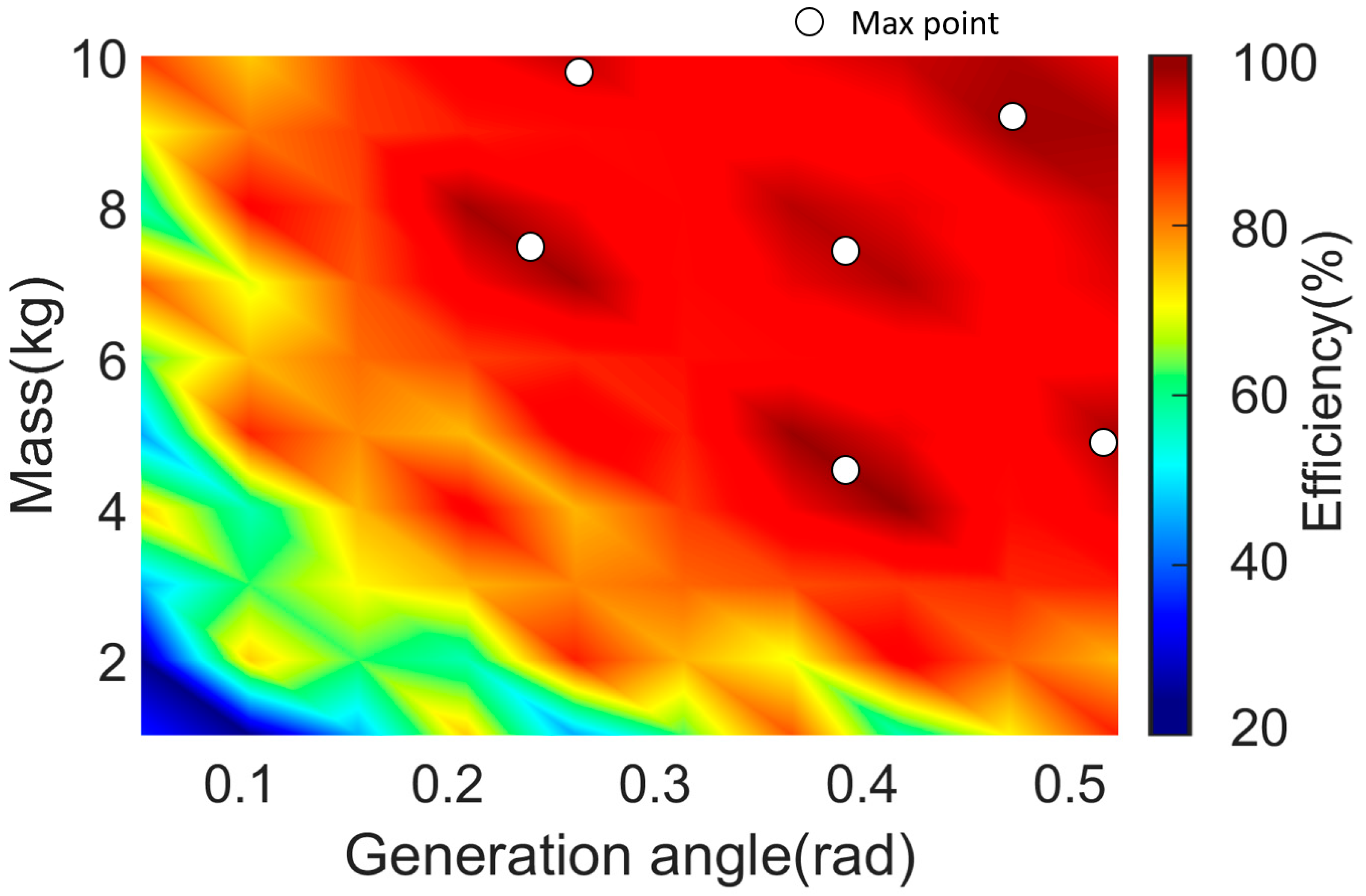
Figure 7 is a color map showing the efficiency depending on the mass of the pendulum and the power generation angle α, where the pendulum length l was fixed at 1 m. On this color map, the white circles indicate points of maximum generator efficiency for a certain section; a pendulum mass of 4 kg and the generation angle α of 7 π/60 characterize one of the maximum efficiency points. These results show that the efficiency of the pendulum resonance generator is determined by the mass of the pendulum and the power generation angle. Moreover, from Figure 5 and 6, the pendulum length does not affect the power generation efficiency; it only affects the power generation time. Therefore, the design variables used in generator design should be properly selected and verified using a mathematical model to achieve optimum efficiency within the desired size.

4. Conclusions

This study derived a mathematical model for generator design using the resonance of the pendulum and presented a generator efficiency map that considers pendulum mass, pendulum length, and the power generation angle. In the design of energy harvesting devices with pendulums, this map will help determine the length of the pendulum according to the installation space and it can then determine the mass and power generation angle for optimal efficiency.
This study obtained the following main results:
  • A mathematical analysis model of a generator using the resonance of the pendulum was constructed, and the time taken to start power generation and the amount of work input to the generator were derived.
  • The potential energy of the pendulum was defined as amount of power generated the pendulum from the power generation angle at which power generation was started, and the output work of the generator was derived.
  • The efficiency of the generator was defined using the work input to the generator and the work output, and the design variables affecting the generator efficiency were presented.
  • The effect of the design variables on the efficiency of the generator was confirmed using an efficiency graph that considered the pendulum length, pendulum mass, and the angle at which power generation is started.
  • As an additional study, it may be possible to manufacture an energy harvesting device using the resonance of the pendulum and measure the power generation efficiency according to design factors.
  • To consider the practical effect of the energy harvesting device using the resonance of the pendulum in this study, future studies on the model including the pre-generator and motor and generator (MG) may be conducted.

Author Contributions

Methodology, S.L.; Project administration, H.K.; Software S.L.; Writing—review & editing, H.K. All authors have read and agreed to the published version of the manuscript.

Funding

1. This research was supported by the MSIT (Ministry of Science and ICT), Korea, under the Grand Information Technology Research Center support program (IITP-2022-2020-0-01791) supervised by the IITP (Institute for Information & communications Technology Planning & Evaluation). 2. This work was supported by the National Research Foundation of Korea (NRF) grant funded by the Korea government (MSIT) (No. NRF-2021R1F1A1062389).

Conflicts of Interest

The authors declare no conflict of interest.

References

  1. Withagen, C. Pollution and Exhaustibility of Fossil Fuels. Resour. Energy Econ. 1994, 16, 235–242. [Google Scholar] [CrossRef]
  2. Perera, F. Pollution from Fossil-Fuel Combustion Is the Leading Environmental Threat to Global Pediatric Health and Equity: Solutions Exist. Int. J. Environ. Res. Public Health 2018, 15, 16. [Google Scholar] [CrossRef] [PubMed] [Green Version]
  3. Nicoletti, G.; Arcuri, N.; Nicoletti, G.; Bruno, R. A Technical and Environmental Comparison between Hydrogen and Some Fossil Fuels. Energy Convers. Manag. 2015, 89, 205–213. [Google Scholar] [CrossRef]
  4. Sodano, H.A.; Inman, D.J.; Park, G. A Review of Power Harvesting from Vibration Using Piezoelectric Materials. Shock Vib. Dig. 2004, 36, 197–205. [Google Scholar] [CrossRef] [Green Version]
  5. Borowiec, M.; Litak, G.; Rysak, A.; Mitcheson, P.D.; Toh, T.T. Dynamic Response of a Pendulum-Driven Energy Harvester in the Presence of Noise. In Proceedings of the 13th International Conference on Micro and Nanotechnology for Power Generation and Energy Conversion Applications (PowerMEMS 2013), London, UK, 3–6 December 2013. [Google Scholar]
  6. Andreeva, T.; Alevras, P.; Naess, A.; Yurchenko, D. Dynamics of a Parametric Rotating Pendulum under a Realistic Wave Profile. Int. J. Dyn. Control 2016, 4, 233–238. [Google Scholar] [CrossRef]
  7. Yurchenko, D.; Alevras, P. Dynamics of the N-Pendulum and Its Application to a Wave Energy Converter Concept. Int. J. Dyn. Control 2013, 1, 290–299. [Google Scholar] [CrossRef] [Green Version]
  8. Alevras, P.; Brown, I.; Yurchenko, D. Experimental Investigation of a Rotating Parametric Pendulum. Nonlinear Dyn. 2015, 81, 201–213. [Google Scholar] [CrossRef]
  9. Bosso, N.; Magelli, M.; Zampieri, N. Application of Low-Power Energy Harvesting Solutions in the Railway Field: A Review. Veh. Syst. Dyn. 2021, 59, 841–871. [Google Scholar] [CrossRef]
  10. Gorlatova, M.; Wallwater, A.; Zussman, G. Networking Low-Power Energy Harvesting Devices: Measurements and Algorithms. IEEE Trans. Mob. Comput. 2013, 12, 1853–1865. [Google Scholar] [CrossRef]
  11. Jesús, D.; Villarreal, Y. VIV Resonant Wind Generators. In Project Vortex Bladeless; European Commission: Brussels, Belgium, 2018. [Google Scholar]
  12. Marszal, M.; Witkowski, B.; Jankowski, K.; Perlikowski, P.; Kapitaniak, T. Energy Harvesting from Pendulum Oscillations. Int. J. Non. Linear. Mech. 2017, 94, 251–256. [Google Scholar] [CrossRef]
  13. Abohamer, M.K.; Awrejcewicz, J.; Starosta, R.; Amer, T.S.; Bek, M.A. Influence of the Motion of a Spring Pendulum on Energy-Harvesting Devices. Appl. Sci. 2021, 11, 8658. [Google Scholar] [CrossRef]
  14. Izadgoshasb, I.; Lim, Y.Y.; Tang, L.; Padilla, R.V.; Tang, Z.S.; Sedighi, M. Improving Efficiency of Piezoelectric Based Energy Harvesting from Human Motions Using Double Pendulum System. Energy Convers. Manag. 2019, 184, 559–570. [Google Scholar] [CrossRef]
  15. Elwi, T.A. Novel UWB Printed Metamaterial Microstrip Antenna Based Organic Substrates for RF-Energy Harvesting Applications. AEU-Int. J. Electron. Commun. 2019, 101, 44–53. [Google Scholar] [CrossRef]
  16. Elwi, T.A.; Al-Saegh, A.M. Further Realization of a Flexible Metamaterial-Based Antenna on Indium Nickel Oxide Polymerized Palm Fiber Substrates for RF Energy Harvesting. Int. J. Microw. Wirel. Technol. 2021, 13, 67–75. [Google Scholar] [CrossRef]
  17. Elwi, T.A.; Hassain, Z.A.A.; Tawfeeq, O.A. Hilbert Metamaterial Printed Antenna Based on Organic Substrates for Energy Harvesting. IET Microw. Antennas Propag. 2019, 13, 2185–2192. [Google Scholar] [CrossRef]
  18. Elwi, T.A.; Jassim, D.A.; Mohammed, H.H. Novel Miniaturized Folded UWB Microstrip Antenna-Based Metamaterial for RF Energy Harvesting. Int. J. Commun. Syst. 2020, 33, e4305. [Google Scholar] [CrossRef]
  19. Abdulmjeed, A.; Elwi, T.A.; Kurnaz, S. Metamaterial Vivaldi Printed Circuit Antenna Based Solar Panel for Self-Powered Wireless Systems. Prog. Electromagn. Res. M 2021, 102, 181–192. [Google Scholar] [CrossRef]
  20. Ghadeer, S.H.; Sharul, S.K.; Elwi, T.A. Solar Panel Integrated 3D MIMO Antenna Array for Modern Communication Systems. In Proceedings of the 2021 International Conference on Applications of Computer Algebra ACA 2021, Maysan, Iraq, 25–26 July 2021. [Google Scholar] [CrossRef]
  21. Fan, Y.; Ghayesh, M.H.; Lu, T.F. High-Efficient Internal Resonance Energy Harvesting: Modelling and Experimental Study. Mech. Syst. Signal Process. 2022, 180, 109402. [Google Scholar] [CrossRef]
  22. Bradai, S.; Naifar, S.; Keutel, T.; Kanoun, O. Electrodynamic Resonant Energy Harvester for Low Frequencies and Amplitudes. In Proceedings of the Conference Record—IEEE Instrumentation and Measurement Technology Conference, Montevideo, Uruguay, 12–15 May 2014. [Google Scholar]
  23. Xu, J.; Tang, J. Modeling and Analysis of Piezoelectric Cantilever-Pendulum System for Multi-Directional Energy Harvesting. J. Intell. Mater. Syst. Struct. 2017, 28, 323–338. [Google Scholar] [CrossRef]
  24. Wu, Y.; Qiu, J.; Zhou, S.; Ji, H.; Chen, Y.; Li, S. A Piezoelectric Spring Pendulum Oscillator Used for Multi-Directional and Ultra-Low Frequency Vibration Energy Harvesting. Appl. Energy 2018, 231, 600–614. [Google Scholar] [CrossRef]
  25. Kecik, K. Assessment of Energy Harvesting and Vibration Mitigation of a Pendulum Dynamic Absorber. Mech. Syst. Signal Process. 2018, 106, 198–209. [Google Scholar] [CrossRef]
  26. Zhu, M.; Yi, Z.; Yang, B.; Lee, C. Making Use of Nanoenergy from Human—Nanogenerator and Self-Powered Sensor Enabled Sustainable Wireless IoT Sensory Systems. Nano Today 2021, 36, 101016. [Google Scholar] [CrossRef]
  27. Khatua, D.K.; Kim, S.-J. Perspective on the Development of High Performance Flexible Piezoelectric Energy Harvesters. J. Mater. Chem. C 2022, 10, 2905–2924. [Google Scholar] [CrossRef]
  28. Sahu, M.; Vivekananthan, V.; Hajra, S.; Khatua, D.K.; Kim, S.J. Porosity Modulated Piezo-Triboelectric Hybridized Nanogenerator for Sensing Small Energy Impacts. Appl. Mater. Today 2021, 22, 100900. [Google Scholar] [CrossRef]
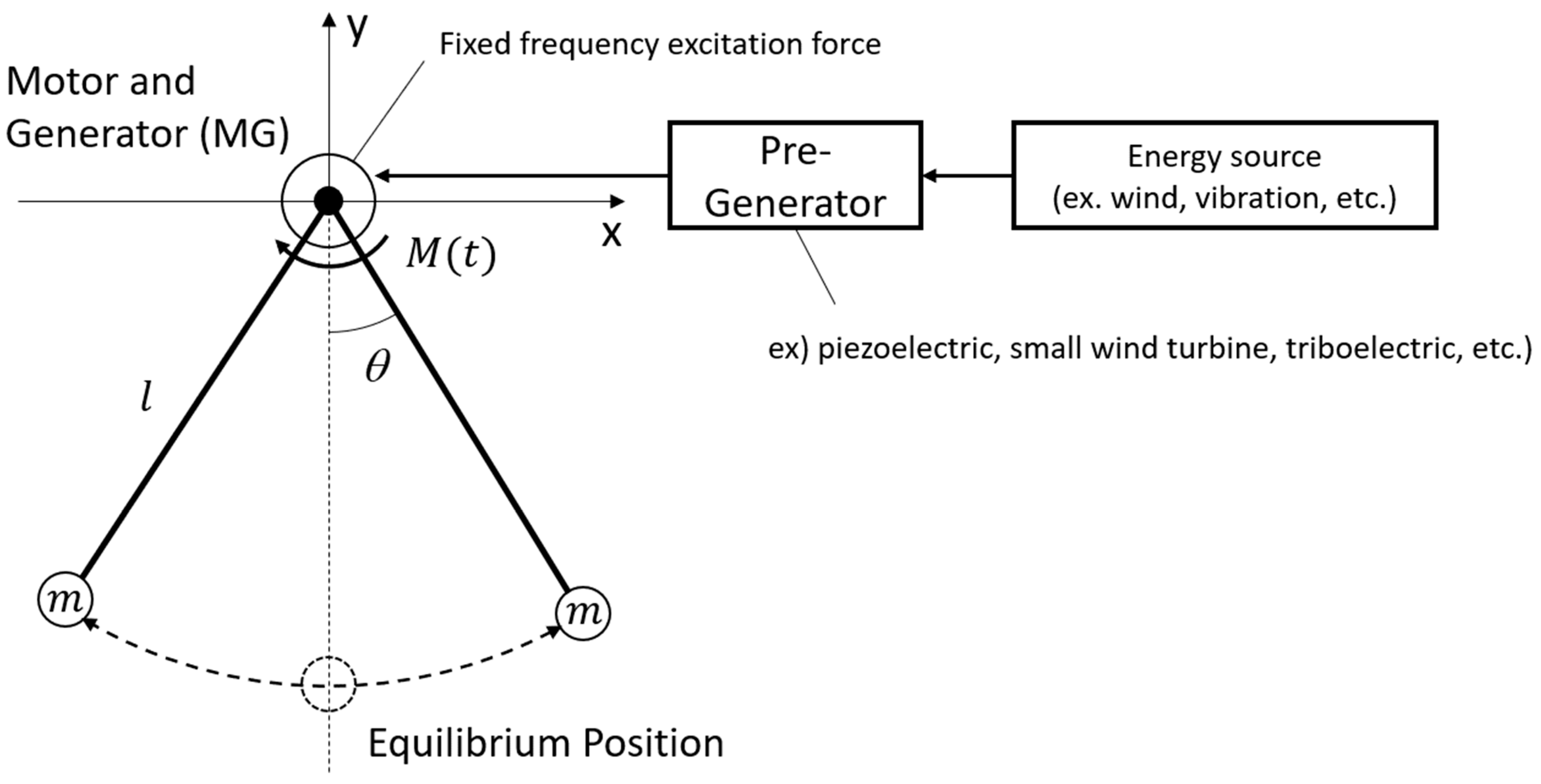
Figure 1. Generator using the resonance of the pendulum model.
Applsci 12 11862 g001
Figure 2. Angular displacement of the pendulum θ .
Applsci 12 11862 g002
Figure 3. Absolute value of pendulum displacement with mass.
Applsci 12 11862 g003
Figure 4. Time to reach the angle of generation according to the mass and length of the pendulum.
Applsci 12 11862 g004
Figure 5. Generation efficiency according to the length and mass of the pendulum.
Applsci 12 11862 g005
Figure 6. Generation efficiency according to α and pendulum length.
Applsci 12 11862 g006
Figure 7. Generation efficiency according to α and pendulum mass.
Applsci 12 11862 g007
Table 1. Power generation angles by mass.
Mass of Pendulum Time   to   α   ( T α ) Δ   t
t 1 1 kg3.42 s-
t 2 1.4 kg4.49 s1.05 s
t 3 1.8 kg6.37 s1.88 s
t 4 2.2 kg7.42 s1.05 s
t 5 2.4 kg8.46 s1.04 s
Publisher’s Note: MDPI stays neutral with regard to jurisdictional claims in published maps and institutional affiliations.