Abstract
The spinal hybrid elastic (SHE) rod is a semi-rigid pedicle screw-based rod for spinal dynamic stabilization. This study investigated the biomechanical effects of different ratios of SHE rod using finite element analysis (FEA). A three-dimensional nonlinear FEA of an intact lumbar spine model (INT) was constructed. The SHE rod was composed of an inner nitinol stick (NS) and an outer polycarbonate urethane shell (PS). Four groups implanted at L3–L4 had the same outer diameter (5.5 mm) but different NS diameter/PS thickness ratios: Nt45, Nt35, Nt25, and Nt15. The resultant intervertebral range of motion (ROM), disc stress, facet joint contact force, screw stress, NS stress, and PCU stress were analyzed. The results indicated that ROM, disc stress, and facet force decreased moderately in the implanted L3–L4 levels and increased slightly in the adjacent L2–L3 levels. The NS stress and NS diameter trended towards inverse proportionality. Changing the ratio did not markedly influence screw or PS stress. The SHE rod system with elastic NS and insulated PS has a 5.5 mm diameter for universal pedicle screws. The SHE rod system provides sufficient spinal support and increases gentle adjacent segment stress. Considering the durability, the optimal NS diameter/PS thickness ratio of the SHE rod system is 3.5/2.0 mm.
1. Introduction
Posterior spinal instrumentation with the pedicle screw-based system is indicated for the treatment of scoliosis, kyphosis, vertebral fractures, spondylolisthesis, spondylolysis, and degenerative disc diseases [1,2]. Fusion with interbody fusion can more effectively strengthen spinal fixation [3,4]. However, various complications are associated with poor fixation and ineffective fusion [5]. Rigid fusion not only fixes the surgical spine, but also increases the displacement and pressure of adjacent levels, and can thus result in adjacent segment disease (ASD) and failed back surgery syndrome (FBSS) [6,7].
A nonfusion dynamic stabilization system was previously developed to support the spine and preserve physiological functions. This system reduces the risks of ASD and FBSS [8,9]; however, existing systems have shortcomings such as complex structures, difficult operation, and lack of durability [10,11]. To design a perfect dynamic stabilization system, the mechanical structure and material selection should be simultaneously improved [12,13].
The spinal hybrid elastic (SHE) rod is a semi-rigid pedicle screw-based rod intended for use with universal pedicle screws. The SHE rod is composed of an inner nitinol stick (NS) and an outer polycarbonate urethane shell (PS). This finite element analysis (FEA) analysis study was conducted to investigate the precise ratio of the thicknesses of the NS and PS. We hypothesized that an optimal SHE rod ratio can provide sufficient spine support, gentle adjacent segment stress, and remarkable durability.
2. Materials and Methods
2.1. Finite Element Model Construction of the Lumbar Spine
A three-dimensional, nonlinear finite element model of the human lumbar spine was created using the commercial software ANSYS 14.5 (ANSYS Inc., Canonsburg, PA, USA). The material properties of the intact lumbar spine model (INT) were investigated in previous studies [14,15,16,17]. The geometrical structure of our INT model was constructed from the computer tomographic images of the lumbar spine in a 19-year-old male. Each coronal plane slice was obtained by the 3 mm interval and enlarged to identify the different regions of the tissues. The edge of the spinal disc and the geometry of the nucleus were measured and referred to Panagiotacopulos et al.’s study [18]. Of the total disc area, 30–50% was defined as the nucleus and the rest was assumed as the disc annulus. The range of motion (ROM) of the INT was compared with that of cadaveric specimens in in vitro testing. The reliability and similar stiffness were validated [19]. The present mesh density was selected based on the convergence test and the model validated in our previous studies [14,16]. Overall, the discrepancy between the in vitro tests and our finite element simulation was within one standard deviation. The model also contained intervertebral discs, endplates, posterior bony elements, and seven ligaments. These intervertebral discs were composed of a ground substance, hyperelastic annulus fibrosus, and incompressible nucleus pulposus with 12 double-cross-linked fiber layers embedded in the ground substance (Table 1).

Table 1.
Material properties used in the finite element model.
2.2. Boundary and Loading Conditions
All models were constrained at the bottom of the L5 vertebrae. For INT, two load steps were imposed within the finite element models. During the first loading step, a perpendicular axial force of 150 N was loaded to the top of the L1 spine. In the second load step, a pure unconstrained moment was applied to ensure that the resultant ROM of the L1 to L5 spine was equal for all motions. The displacement control angle was determined using the minimally incremental force method. A load was applied with flexion 24°, extension 12.6°, torsion 18.8°, and lateral bending 24.8°. The boundary load is the maximum load. Applying a constant ROM was proven to be applicable in predicting adjacent segment effects after spinal implantation [16]. The resultant intervertebral ROM and stress of the intervertebral disc and facet joint contact forces were analyzed. Distortion energy theory was applied to the intervertebral discs. The von Mises stress of each model was obtained after applying torque in each direction of the model.
2.3. FEA Construction of Implants
Four pedicle screws and two SHE rods were implanted at the L3–L4 level of the spinal model. The material parameters of each element were obtained from previous research (Table 2) [17,20]. The diameter of the titanium alloy pedicle screw was set to 6.4 mm without threads. The interface between the pedicle screw, bone, PS, and NS was simulated for the bonded contact. The SHE rod is composed of an inner NS and outer PS. The outer diameter of the SHE rod was uniformly set to 5.5 mm. These groups had different NS diameter/PS thickness ratios: Nt45 (4.5/1.0), Nt35 (3.5/2.0), Nt25 (2.5/3.0), and Nt15 (1.5/4.0) (Figure 1; Table 3).
Table 2.
Material properties of implants used in FEM.
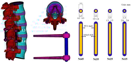
Figure 1.
Overview of the finite element model and SHE rod dynamic stabilization system. Systems with different NS diameter/PS thickness ratios of the SHE rods were implanted into the L3–L4 spine model.
Table 3.
The elements and nodes of the five finite element models.
3. Results
This paper presents the results in two parts. First, the ROM, disc stress, and facet force in the instrumented groups were compared with those in the INT group. Second, the biomechanical behaviors of the screw, NS, and PS were compared with that of Nt45. The detailed biomechanical analyses of the five finite element models in flexion, extension, torsion, and lateral bending are presented as Supplementary Tables S1–S4.
3.1. The Intervertebral ROM
At the implanted L3–L4 levels, the ROM in all models decreased compared with the INT to a degree of 56–62% in extension, which is similar to flexion (57–60%). The ROM further decreased by 4–18% in torsion and 49–57% in lateral bending. In contrast, the ROM of the cephalic adjacent L2–L3 levels all increased—by 17–19% during flexion, 13–15% during extension, 1–5% during torsion, and 14–17% during lateral bending (Table 4).
Table 4.
Comparison of intervertebral range of motion (degree) in finite element models.
Overall, the differences between these models were within 5% for both flexion and extension. There was a downward trend in ROM changes at all levels as the NS diameter decreased (Figure 2).
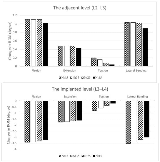
Figure 2.
Changes in the ROM normalized and compared with the INT at the adjacent L2–L3 level (top) and the implanted L3–L4 level (bottom). The ROMs were all increased at L2–L3 and all decreased at L3–L4. There was a downward trend in ROM changes at all levels as the NS diameter became smaller.
3.2. Intervertebral Disc Stress
At the implanted L3–L4 level, the disc stress in all models decreased when compared with INT (Table 5). The disc stress decreased by 31–33% in flexion, where the maximum occurred in the anterior superior edge; 42–43% in extension, where the maximum occurred in the posterior inferior edge; 3–19% in torsion, where the maximum occurred in the left inferior edge; and by 45–55% in lateral bending, where the maximum occurred in the left superior edge.
Table 5.
Comparison of stress of intervertebral disc (KPa) in finite element models. The von Mises stress on the intervertebral disc. The NS diameter was inversely proportional to the disc stress at the implanted L3–L4 level; it did not markedly influence the disc stress at the adjacent L2–L3 level.
In contrast, the disc stress of the cephalic L2–L3 adjacent levels all increased. This parameter increased by 24–27% in flexion, where the maximum occurred in the anterior superior edge (Figure 3); by 12–14% in extension, where the maximum occurred in the posterior inferior edge; by 0–7% in torsion, where the maximum occurred in the left inferior edge; and by 21–24% in lateral bending, where the maximum occurred in the left superior edge.
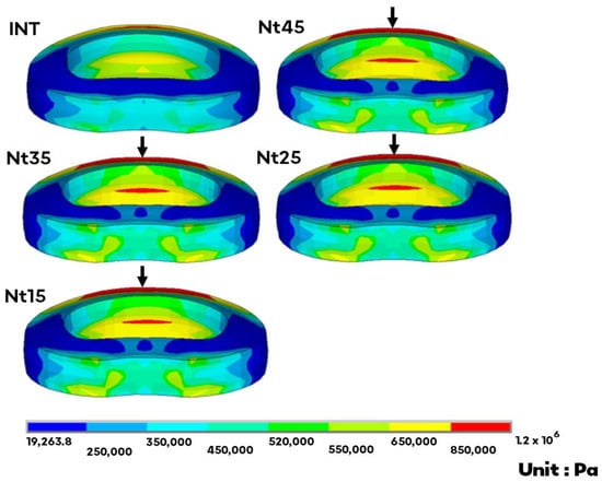
Figure 3.
The von Mises stress distribution of the adjacent L2–L3 disc in flexion. The arrow indicates the maximum at the anterior superior edge. There was no obvious trend in disc stress at the adjacent level as the NS diameter changed.
Overall, the differences between these models were within 10%, except for torsion at the implant level. The NS diameter was inversely proportional to the disc stress at the implant level; it did not markedly influence the disc stress at the adjacent level.
3.3. Facet Joint Contact Force
There was no facet force during flexion in any of the models. At the implanted L3–L4 levels, the facet force in all models decreased compared with the INT, by 87–95% in extension, 4–37% in torsion, and 79–100% in lateral bending. The Nt45 model showed the greatest decrease (Table 6).
Table 6.
Comparison of facet joint contact forces (N) in finite element models.
In contrast, the facet force of the adjacent cephalic L2–L3 levels all increased, by 23–25% and 40–55% in extension and lateral bending, respectively, where the maximum occurred on Nt35, while it increased by 2–11% in torsion, and the maximum occurred on Nt45.
3.4. Screw Stress
In flexion, the screw stress on Nt35 increased by 1% when compared with Nt45, whereas the other models decreased by 4–6%. The screw stress increased by 5–7% and 11–15% during extension and lateral bending, respectively, and decreased by 23–53% in torsion. For all motions, the screw stress of all models ranged between 98.9 and 211 MPa, and the maximum occurred on Nt45 in torsion (Table 7).
Table 7.
Comparison of the maximum von Mises stress on rods (MPa) in finite element models. There was no obvious trend in outer PS stress as the NS diameter changed. The stress on the inner nitinol stick increased as the NS diameter decreased.
3.5. PS Stress
In flexion and lateral bending, the PS stress increased by 4% and 6% on Nt15 compared with Nt45. Except for these two models, the other models decreased by 26–74%. There was no obvious trend in PS stress as the NS diameter changed. In all motions, the PS stress of all the models was between 2.7 and 17.4 MPa, and the maximum occurred on the Nt45 in torsion (Table 7).
3.6. NS Stress
In flexion, extension, torsion, and lateral bending, the NS stress increased by 24–168%, 16–156%, 48–75%, and 14–117% when compared with Nt45 (Table 7). The NS stress increased as the NS diameter decreased, and the maximum stress occurred in the lower-third portion. For all motions, the NS stress of all models was between 39.5 and 383 MPa, and the maximum occurred on Nt25 in torsion (Figure 4).
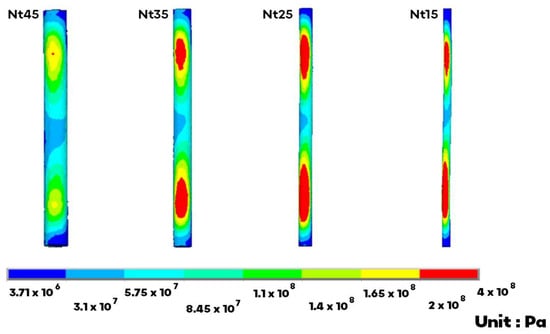
Figure 4.
The von Mises stress on the inner NS markedly increased on the upper and lower portion. The maximum occurred on the Nt25 in torsion.
3.7. SHE Rod Stress
The SHE rod stress comprises both the PS and NS stresses. In flexion, extension, torsion, and lateral bending, the SHE rod stress increased by 18–152%, 9–137%, 40–65%, and 12–111% when compared with Nt45, and the greatest increase occurred on Nt15. The SHE rod stress increased as the NS diameter decreased. For all motions, the SHE rod stress of all models was between 44.6 and 389 MPa, and the maximum occurred on Nt25 in torsion.
4. Discussion
The SHE rod dynamic stabilization system is intended to balance the stability and motion of the spine after surgery. In this study, the overall trend indicated that ROM, disc stress, and facet force decreased moderately in the implanted L3–L4 levels and increased mildly in the adjacent L2–L3 levels. Nevertheless, the stress shielding effect on adjacent levels is mild. The present results demonstrate that the SHE rod can provide good spinal stability and avoid high loading at the adjacent levels.
PEEK (polyether ether ketone) is a low elastic modulus, similar to that of bone (3.6 GPa), and less rigid than titanium (115 GPa) [21]. The PEEK rod is nonrigid and has recently been used to stabilize the spine dynamically. PEEK rods closely approximate physiologic load sharing [22]. However, the hard surface, durability, and fatigue fracture of PEEK rods should be of concern. They were associated with initiating scratching at the rod–screw interface and needed larger-diameter, locked-in, specific pedicle screws [23]. Compared to the PEEK rod, the outer PCU shell is scratch resistant. The SHE rod system has a 5.5 mm diameter for universal pedicle screws. However, it is still necessary to compare the two materials in further biomechanical research.
Nitinol is an elastic shape memory alloy that minimizes stress shielding and has even been shown to trend toward superior fatigue resistance compared with titanium [24]. However, nitinol is not a popular material in orthopedic applications because of its poor corrosion resistance and anti-wear properties [25]. To this end, we introduced a PCU polymer as an insulator. The outer PCU shell enveloped the inner Nitinol stick, providing perfect insulation against the titanium screw heads and nuts. In the present FEA, the NS stress increased markedly in the upper and lower portions. This phenomenon is directly related to the connection between the screw head and nut. Nevertheless, the NS stress was always lower than the yield strength of nitinol (816 MPa) [26]. NS in the SHE system has a low potential implant failure rate. Even in the worst-case scenario of the thinnest PS of the SHE rod system (Nt45) after rod fracture, the biomechanical effects still afford nearly sufficient spine support and gentle adjacent segment stress [27].
The spacer in the Dynesys system is made of PCU, which is the same material as PS [19]. The stabilization of the pretension provided by the spacer and cord in Dynesys differs from that in the SHE rod system. In addition, PCU is less rigid than nitinol. The outer PS stress decreased under the same load owing to the stress shielding by the inner NS. As such, we observed no obvious trend in PS stress as the NS diameter was changed. In most of the present models, the PS stress decreased. The maximum PS stress was still much lower than the mean tensile strength of the PCU (30 MPa) [13]. Though the materials in Dynesys were different to those in the SHE rod system, they both have the same intended use [28]. The SHE rod system provides no inferior spinal support compared with the Dynesys system.
No other single clinical material can exhibit biphasic rigidity and flexibility. There-fore, we propose the hybrid use of semi-rigid and flexible materials. The semi-rigid nitinol is used for the inner stick, and the flexible PCU is used for the outer shell. A commercially available SHE rod was devised based on the results of the precise ratio of the hybrid used in this study. Considering the industrial technologies, the PCU shell is too thin in Nt45 to manufacture. The optimal NS diameter/PS thickness ratio of the SHE rod system should be 3.5/2.0 mm due to the lower stress concentrations for the durability of the implant.
This study had some limitations. All spinal models were healthy with no pathological properties or defects. Degeneration or fractures are common in patients, and posterior decompression is often performed following spinal fixation. As such, the models we applied did not exactly coincide with common clinical situations. The interface between the pedicle screw and PS was simulated to be bonded, as was that between the PS and NS. The model presents an idealized fabrication of the SHE rod.
5. Conclusions
The SHE rod system has a 5.5 mm diameter for universal pedicle screws. The inner Nitinol is elastic to minimize stress shielding. The outer PCU shell is insulated and scratch resistant. The SHE rod system provides sufficient spinal support and increases gentle adjacent segment stress. Considering the durability of the implants, the optimal NS diameter/PS thickness ratio of the SHE rod system is 3.5/2.0 mm.
Supplementary Materials
The following supporting information can be downloaded at: https://www.mdpi.com/article/10.3390/app122211759/s1.
Author Contributions
Conceptualization, J.-Y.H. and C.-S.C.; data curation and methodology, C.-S.C. and S.-M.C.; validation and formal analysis, J.-Y.H. and Y.-Y.H.; writing, J.-Y.H. and S.-M.C.; review and editing, C.-S.C. and P.-Q.C.; investigation and supervision, Y.-Y.H., J.-H.W. and P.-Q.C. All authors have read and agreed to the published version of the manuscript.
Funding
This study was approved by the National Taiwan University Hospital and its Jinshan branch.
Institutional Review Board Statement
Not applicable.
Informed Consent Statement
Not applicable.
Data Availability Statement
Not applicable.
Acknowledgments
The authors wish to thank all the members who participated in this study.
Conflicts of Interest
The authors declare no conflict of interest.
References
- Lykissas, M.G.; Jain, V.V.; Nathan, S.T.; Pawar, V.; Eismann, E.A.; Sturm, P.F.; Crawford, A.H. Mid- to long-term outcomes in adolescent idiopathic scoliosis after instrumented posterior spinal fusion: A meta-analysis. Spine 2013, 38, E113–E119. [Google Scholar] [CrossRef] [PubMed]
- Noorian, S.; Sorensen, K.; Cho, W. A systematic review of clinical outcomes in surgical treatment of adult isthmic spondylolisthesis. Spine J. 2018, 18, 1441–1454. [Google Scholar] [CrossRef]
- Mobbs, R.J.; Phan, K.; Malham, G.; Seex, K.; Rao, P.J. Lumbar interbody fusion: Techniques, indications and comparison of interbody fusion options including PLIF, TLIF, MI-TLIF, OLIF/ATP, LLIF and ALIF. J. Spine Surg. 2015, 1, 2–18. [Google Scholar] [CrossRef] [PubMed]
- Levin, J.M.; Tanenbaum, J.E.; Steinmetz, M.P.; Mroz, T.E.; Overley, S.C. Posterolateral fusion (PLF) versus transforaminal lumbar interbody fusion (TLIF) for spondylolisthesis: A systematic review and meta-analysis. Spine J. 2018, 18, 1088–1098. [Google Scholar] [CrossRef]
- Hu, Y.-H.; Niu, C.-C.; Hsieh, M.-K.; Tsai, T.-T.; Chen, W.-J.; Lai, P.-L. Cage positioning as a risk factor for posterior cage migration following transforaminal lumbar interbody fusion—An analysis of 953 cases. BMC Musculoskelet. Disord. 2019, 20, 260. [Google Scholar] [CrossRef]
- Zhang, C.; Berven, S.H.; Fortin, M.; Weber, M.H. Adjacent Segment Degeneration Versus Disease After Lumbar Spine Fusion for Degenerative Pathology: A Systematic Review With Meta-Analysis of the Literature. Clin. Spine Surg. 2016, 29, 21–29. [Google Scholar] [CrossRef]
- Sebaaly, A.; Lahoud, M.-J.; Rizkallah, M.; Kreichati, G.; Kharrat, K. Etiology, Evaluation, and Treatment of Failed Back Surgery Syndrome. Asian Spine J. 2018, 12, 574–585. [Google Scholar] [CrossRef] [PubMed]
- Pan, A.; Hai, Y.; Yang, J.; Zhou, L.; Chen, X.; Guo, H. Adjacent segment degeneration after lumbar spinal fusion compared with motion-preservation procedures: A meta-analysis. Eur. Spine J. 2016, 25, 1522–1532. [Google Scholar] [CrossRef]
- Lee, C.-H.; Jahng, T.-A.; Hyun, S.-J.; Kim, C.H.; Park, S.-B.; Kim, K.-J.; Chung, C.K.; Kim, H.-J.; Lee, S.-E. Dynamic stabilization using the Dynesys system versus posterior lumbar interbody fusion for the treatment of degenerative lumbar spinal disease: A clinical and radiological outcomes-based meta-analysis. Neurosurg. Focus 2016, 40, E7. [Google Scholar] [CrossRef]
- Wu, A.-M.; Zhou, Y.; Li, Q.-L.; Wu, X.; Jin, Y.-L.; Luo, P.; Chi, Y.-L.; Wang, X.-Y. Interspinous Spacer versus Traditional Decompressive Surgery for Lumbar Spinal Stenosis: A Systematic Review and Meta-Analysis. PLoS ONE 2014, 9, e97142. [Google Scholar] [CrossRef] [PubMed]
- Phan, K.; Rao, P.J.; Ball, J.R.; Mobbs, R.J. Interspinous process spacers versus traditional decompression for lumbar spinal stenosis: Systematic review and meta-analysis. J. Spine Surg. 2016, 2, 31–40. [Google Scholar] [CrossRef] [PubMed]
- Kok, D.; Firkins, P.J.; Wapstra, F.H.; Veldhuizen, A.G. A new lumbar posterior fixation system, the memory metal spinal system: An in-vitro mechanical evaluation. BMC Musculoskelet. Disord. 2013, 14, 269. [Google Scholar] [CrossRef] [PubMed]
- Kojio, K.; Furukawa, M.; Motokucho, S.; Shimada, M.; Sakai, M. Structure−Mechanical Property Relationships for Poly(carbonate urethane) Elastomers with Novel Soft Segments. Macromolecules 2009, 42, 8322–8327. [Google Scholar] [CrossRef]
- Chen, S.-H.; Zhong, Z.-C.; Chen, C.-S.; Chen, W.-J.; Hung, C. Biomechanical comparison between lumbar disc arthroplasty and fusion. Med. Eng. Phys. 2009, 31, 244–253. [Google Scholar] [CrossRef]
- Liu, C.-L.; Zhong, Z.-C.; Shih, S.-L.; Hung, C.; Lee, Y.-E.; Chen, C.-S. Influence of Dynesys System Screw Profile on Adjacent Segment and Screw. Clin. Spine Surg. 2010, 23, 410–417. [Google Scholar] [CrossRef]
- Zhong, Z.-C.; Chen, S.-H.; Hung, C.-H. Load- and displacement-controlled finite element analyses on fusion and non-fusion spinal implants. Proc. Inst. Mech. Eng. Part H J. Eng. Med. 2008, 223, 143–157. [Google Scholar] [CrossRef]
- Liu, C.L.; Zhong, Z.C.; Hsu, H.W.; Shih, S.L.; Wang, S.T.; Hung, C.; Chen, C.S. Effect of the cord pretension of the Dynesys dynamic stabilization system on the biomechanics of the lumbar spine: A finite element analysis. Eur. Spine J. 2011, 20, 1850–1858. [Google Scholar] [CrossRef]
- Panagiotacopulos, N.D.; Pope, M.H.; Krag, M.H.; Block, R. Water Content in Human Intervertebral Discs. Spine 1987, 12, 912–917. [Google Scholar] [CrossRef]
- Yamamoto, I.; Panjabi, M.M.; Crisco, T.; Oxland, T. Three-Dimensional Movements of the Whole Lumbar Spine and Lumbosacral Joint. Spine 1989, 14, 1256–1260. [Google Scholar] [CrossRef]
- Chevalier, V.; Arbab-Chirani, R.; Arbab-Chirani, S.; Calloch, S. An improved model of 3-dimensional finite element analysis of mechanical behavior of endodontic instruments. Oral Surg. Oral Med. Oral Pathol. Oral Radiol. Endodontol. 2010, 109, e111–e121. [Google Scholar] [CrossRef]
- Vadapalli, S.; Sairyo, K.; Goel, V.K.; Robon, M.; Biyani, A.; Khandha, A.; Ebraheim, N.A. Biomechanical Rationale for Using Polyetheretherketone (PEEK) Spacers for Lumbar Interbody Fusion—A Finite Element Study. Spine 2006, 31, E992–E998. [Google Scholar] [CrossRef] [PubMed]
- Gornet, M.F.; Chan, F.W.; Coleman, J.C.; Murrell, B.; Nockels, R.P.; Taylor, B.A.; Lanman, T.H.; Ochoa, J. Biomechanical Assessment of a PEEK Rod System for Semi-Rigid Fixation of Lumbar Fusion Constructs. J. Biomech. Eng. 2011, 133, 081009. [Google Scholar] [CrossRef]
- Kurtz, S.M.; Lanman, T.H.; Higgs, G.; Macdonald, D.W.; Berven, S.H.; Isaza, J.E.; Phillips, E.; Steinbeck, M.J. Retrieval analysis of PEEK rods for posterior fusion and motion preservation. Eur. Spine J. 2013, 22, 2752–2759. [Google Scholar] [CrossRef]
- Massey, P.A.; Hoge, S.; Nelson, B.G.; Ogden, A.L.; Mody, M.G.; Myers, M.; Bilderback, K.; Solitro, G.; Barton, R.S. Nitinol Memory Rods Versus Titanium Rods: A Biomechanical Comparison of Posterior Spinal Instrumentation in a Synthetic Corpectomy Model. Glob. Spine J. 2020, 11, 277–282. [Google Scholar] [CrossRef] [PubMed]
- Yeung, K.W.K.; Poon, R.W.Y.; Liu, X.Y.; Ho, J.P.Y.; Chung, C.Y.; Chu, P.K.; Lu, W.W.; Chan, D.; Cheung, K.M.C. Corrosion resistance, surface mechanical properties, and cytocompatibility of plasma immersion ion implantation-treated nickel-titanium shape memory alloys. J. Biomed. Mater. Res. Part A 2005, 75, 256–267. [Google Scholar] [CrossRef]
- Chen, C.-S.; Shih, S.-L. Biomechanical analysis of a new lumbar interspinous device with optimized topology. Med. Biol. Eng. Comput. 2018, 56, 1333–1341. [Google Scholar] [CrossRef]
- Hsieh, J.-Y.; Chen, C.-S.; Chuang, S.-M.; Wang, J.-H.; Chen, P.-Q.; Huang, Y.-Y. Finite element analysis after rod fracture of the spinal hybrid elastic rod system. BMC Musculoskelet. Disord. 2022, 23, 816. [Google Scholar] [CrossRef] [PubMed]
- Shih, S.L.; Chen, C.S.; Lin, H.M.; Huang, L.Y.; Liu, C.L.; Huang, C.H.; Cheng, C.K. Effect of spacer diameter of the Dynesys dynamic stabilization system on the biomechanics of the lumbar spine: A finite element analysis. Clin. Spine Surg. 2012, 25, E140–E149. [Google Scholar] [CrossRef]
Publisher’s Note: MDPI stays neutral with regard to jurisdictional claims in published maps and institutional affiliations. |
© 2022 by the authors. Licensee MDPI, Basel, Switzerland. This article is an open access article distributed under the terms and conditions of the Creative Commons Attribution (CC BY) license (https://creativecommons.org/licenses/by/4.0/).