Article

8D BIM Model in Urban Rehabilitation Projects: Enhanced Occupational Safety for Temporary Construction Works

by
Alcínia Zita Sampaio
1,2,*,
Gonçalo B. Constantino
1 and
Nuno M. Almeida
1,2
1
Department of Civil Engineering, Higher Technical Institute, University of Lisbon, 1049-001 Lisbon, Portugal
2
CERIS—Civil Engineering Research and Innovation for Sustainability, 1049-001 Lisbon, Portugal
*
Author to whom correspondence should be addressed.
Appl. Sci. 2022, 12(20), 10577; https://doi.org/10.3390/app122010577
Submission received: 8 September 2022 / Revised: 13 October 2022 / Accepted: 18 October 2022 / Published: 20 October 2022

Abstract

:

Featured Application

BIM Implementation in the Construction Industry: Innovation and Challenges.

Abstract

Building Information Modeling (BIM) is a relevant booster to the modernization of construction. The adoption of digital technologies positively contributes to more agile and integrated processes in all phases of the building life-cycle, namely with regard to project management activities. The implementation of BIM has been predominant in new building projects, but the current market cycle of the rehabilitation or refurbishing of existing buildings offers new opportunities of application to be explored. This paper explores such opportunities, namely with regard to the temporary construction works involved in urban rehabilitation projects with the preservation of the façades of the original buildings. It specifically addresses the impacts of the modeling efforts of steel frames and structures needed to temporarily support façades, after the demolition of the old buildings, and until the original façade is reintegrated into the structural elements of the new building. In a BIM context, an 8D model is created to explore BIM capabilities in enabling more efficient occupation safety and health coordination and management activities in building rehabilitation projects, namely in improving and validating the demolitions and construction methods and sequencing, the scheduling of construction works, and the mandatory occupational risk prevention documents for the construction site. The development of the research was supported on the use of the available BIM software: Revit, to model the façade and the temporary steel structural system; Microsoft Project, to schedule the construction works; Navisworks, to perform clash detection analyses and enable visual simulations for occupational risk, and its identification and mitigation. The study intends to contribute to the dissemination of BIM capabilities to improve occupation safety and health in construction, namely in rehabilitation projects involving temporary structures while contributing with innovative perspectives toward higher maturity in BIM implementation and use in the construction sector.

1. Introduction

The construction sector, while being a very important domain within the national economy of a country, presents, however, some inefficiencies. In fact, in a world global context, the annual productivity rating of this sector has only increased by 1% in the last 20 years [1]. The construction industry has been undergoing changes particularly from overdue deadlines, exceeded budgets, reduced construction quality, serious environmental impacts, and one of the lowest performances in term of occupational safety and health [2], when compared to other areas of the economic activity. Currently, the architecture, engineering, and construction (AEC) industry is experiencing a rapid information technology (IT) change due to the digital transformation, bringing new opportunities and new challenges.
The implementation of Building Information Modeling (BIM) in the construction industry has been incrementing in efficiency in project management activities while bringing changes and reorganization among construction professionals and enterprises, following the incorporation of the most advanced technologies as a contribution to digitalize the industry. A methodology such as BIM intends to assist with this transformation and to simplify work processes, but the use of BIM technology has been adopted with some barriers and reservations [3].
Currently, the cloud-based BIM has been providing an important basis for the practice and promotion of interdisciplinary exchange [4]. The quantity and visualization values exchanges among primary stakeholders have been increasing when using the BIM methodology and associated software [5]. Design and construction offices can help employers attract and retain specialized professionals and can positively impact well-being and productivity, thanks to the advanced technologies in use and increased computational power, allowed with BIM adoption [6]. In addition, the circular economy in the building industry, as a disruptive aspect, can be supported in digital technologies, namely BIM, concerning the building phase, the sustainability knowledge about the applied material, and the building demolition process [7].
The efficiency in construction sites can be monitored using a framework supported on the connection of BIM and virtual reality (VR) technologies [8]. Monitoring of construction sites using cameras has become increasingly significant in relation to occupational safety performance, namely in 4D BIM environments, bringing innovative perspectives on the prevention and mitigation of occupational and health risks in construction, which is currently known as the 8D dimension of BIM [9]. Construction site monitoring is an important task in order to analyze, measure, and follow the activities in the construction site, and BIM has been applied in the control of the basic resources in a construction project, namely labor and the occupational risk that need to be managed [10].
The application of the BIM concept and software in the rehabilitation and assessment of heritage buildings has been oriented to identify the characteristics and history of the old building in analyses. Several aspects are normally studied, namely the applied material and antique construction techniques or the visual inspection using semi-destructive tests such as drilling resistance experiments, in order to obtain a current damage or defects mapping, supporting the evaluation of the present conditions of the old building [11]. However, in a HBIM context, the geometry configuration caption methodologies are the most frequent topic, requiring specific approaches and procedures (photogrammetry [12], 3D scan, or drones) in order to generate adequate parametric objects, as it is the basic concept of the BIM modeling process. Old buildings are characterized by presenting a nonregular geometry and being difficult to conceive, but after obtaining a rigorous model, it allows adequate support to experiment with alternative rehabilitation designs, to obtain material volume accurately, to identify the present condition of the structure, and to make predictions of possible future decay scenarios [13]. Thus, the BIM model collects, in detail, the geometrical shape, the material composition, and the structural configuration, and allows the control and management of all the information required to support conservation and repair [14] or refurbishing and rehabilitation [15] of heritage buildings. Thus, the site risk safety and the healthcare aspects are less analyzed in a HBIM context. Only a few studies have focused on compiling relevant information about the safety level of structures and its critical points [16] or monitoring the structural health with advantages in the case of monitoring and maintaining heritage buildings [17]. Both use the BIM model to establish adequate safety strategies. The temporal structure required to contain a heritage set of façades is described in the present study, and when compared to the referred HBIM works, this perspective is a new and important application. Thus, this research is an innovative and necessary work that can improve the integration process with the safety plan, when supported in BIM methodology and software. The point cloud obtained using the 3D scanner is used as an auxiliary reference to survey the model in the BIM platform with the Revit software [18]. The structural topic developed in a HBIM project has also been a recurrent direction of analyses frequently reported [19,20].
The research question of this study is: can 8D BIM be used in urban rehabilitation projects to enhance the occupational safety of temporary construction works?
The present study explores the eighth occupational safety dimension of BIM while proposing a work methodology that can be used in occupation safety coordination and management in construction projects. The study specifically aims to address a research gap in BIM-related studies, namely temporary works that are often outside the scope of BIM efforts. The research question is addressed through an empirical study where a mix of BIM-related software tools are used in combination for enabling conclusions: Revit for modeling; Microsoft Project for planning and scheduling of construction activities; Navisworks for the coordination and simulation of occupational risks in the construction works.
The empirical case study is part of the trend to retrofit existing building envelopes as a strategy for improving the preservation of the history [21]. The present study concerns the preservation of a façade of a heritage urban building, submitted to a full reconstruction of the structural and interior elements. The study was conducted during the rehabilitation intervention process. It illustrates the main aspects of the development of the demolition work and the positioning in place of a temporary support system used to support the building façade to be preserved and integrated into the new structural elements to be erected.
The first and current section of this paper introduces the goals and scope of this study, its originality or novelty, and the research question that is being addressed to contribute to the current research gap. The second section provides an overview of the theoretical literature on 8D BIM and its application to a building renovation project and temporary works. The third section describes the modeling of the physical elements of the empirical case study (3D BIM model). The fourth section describes the modeling of the construction works, namely the sequencing of construction works and activities covered in this study (4D BIM model). The fifth section presents the modeling of projects management integration issues with a focus on occupational safety coordination in construction (8D BIM model). The final section summarizes the conclusions of the paper with regard to the research question.

2. 8D BIM Concept and Application

Sacks et al. [22] were the first to establish the bases for the incorporation of Computer Aided Design (CAD) systems, on the creation of 3D digital models, with the capacity to support different views or characteristics of a building. The digital support of a project encourages the consistency and the coordination of data along the project elaboration. These are premises of information that can be compiled into a single database, accessible for all the stakeholders. Thus, a system was established containing an accessible database concerning a construction project, first named Building Design System (BDS) and later Building Information Modeling (BIM) [23]. There are two main aspects supporting the BIM methodology: the parametric modeling process and the interoperability capacity of the software used.

2.1. Parametric Modeling

Following the main fundamentals of BIM, concerning the centralization of all information, the technology, required to support this concept, has been achieving advanced levels, allowing an efficient implementation of BIM in the sector. The BIM model, created along the development of a building design, is based on the use of parametric objects [24]. Thus, a BIM model is composed of parametric objects representing construction components that enclose not only geometric attributes, but also information about the physical properties of the applied materials.
The current BIM systems contain a diverse type of libraries of parametric families of building components, such as walls, slabs, or columns. At the beginning of the conception phase of each discipline, architecture, structures, or systems, the necessary objects must be selected and adjusted to the project in analyses. The values of the parameters of the objects can be modified according to the project needs, along its development, or after, and some new parameters can be added, in posterior design stages. Thus, over a created BIM model, the user can change and adapt the components of the model consequently with the new or alternative requests in each project step. The methodology allows an important reduction in material costs, by providing a reliable construction cost estimation, based on a rigorous quantity take-off of the materials, before the construction phase begins.
In the present study, two BIM models were created, concerning the façades and the containment system, both using parametric objects. The software used to generate the models was Revit from Autodesk. Some objects were retrieved from the available libraries of the software, and others were created for this specific project in order to allow a realistic representation of the façade components and the containing system structure [25].

2.2. Interoperability
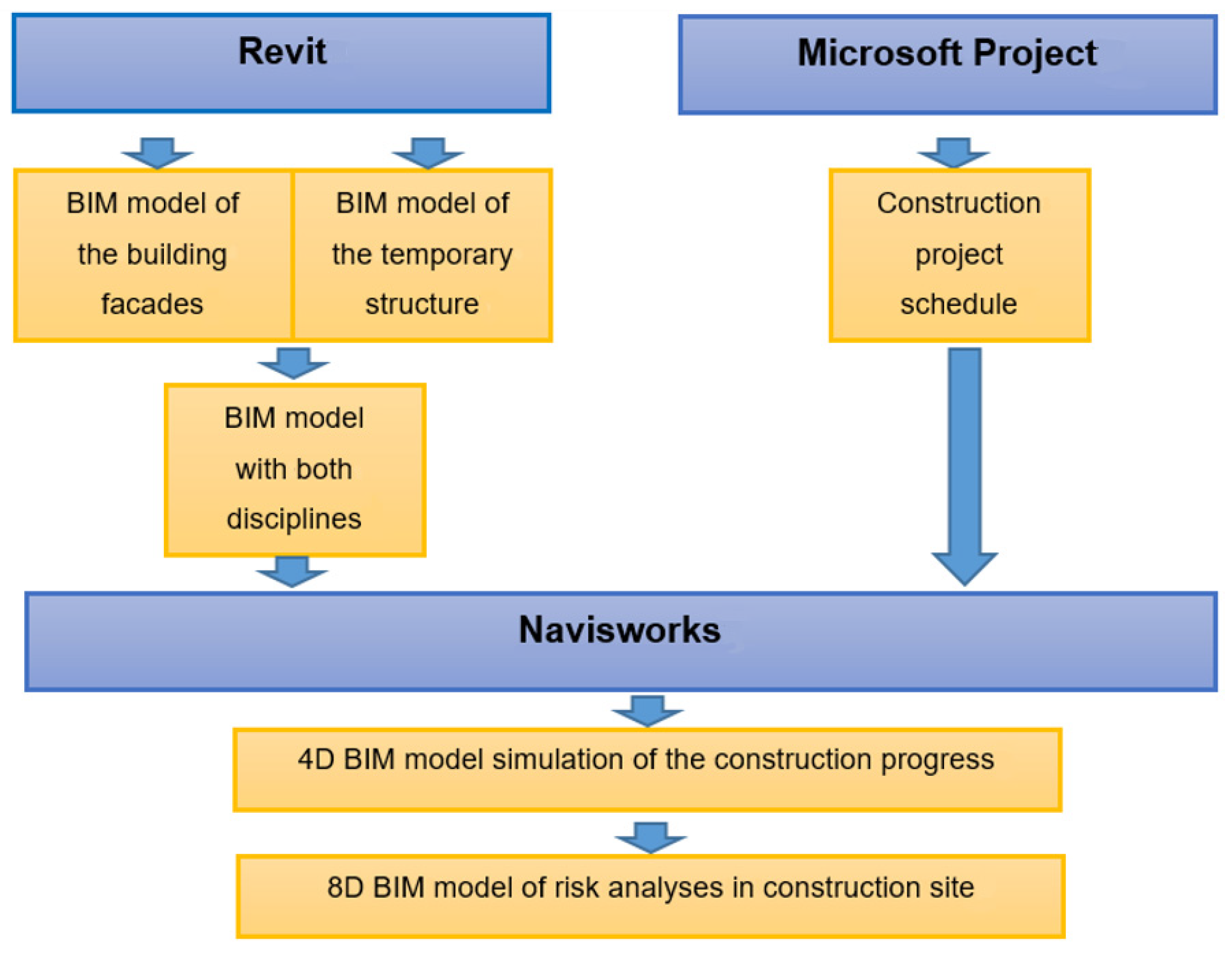
A building project involves several professionals from different specialties, and all of them frequently use different software for their own purpose. Currently, the available BIM systems support a high level of interoperability when the transfer of models between software take place, but a project elaborated over a BIM platform, connecting several pieces software, still presents a limited capacity, bringing problems of efficiency. This limitation constitutes a difficulty in a BIM context, as its main concept requires the generation of a unique centralized model, supported in an efficient transfer of data between systems, without inconsistencies or omissions. The capability of transferring data between applications is referred to as interoperability [26]. The Industry Foundation Class (IFC) is a specific data format that has the purpose to allow the inter-exchange of models between systems without loss or distortion of data. All BIM systems include the capacity of archiving and interpreting BIM models, defined in this global data format, allowing the transference of information along all steps in a building life cycle [27].
In the present research, the systems used, Revit and Navisworks, belong to Autodesk and, thus, the transfer of models between the systems is made in Revit native data format; thus, no IFC format is required. Naviswork allows the importing of several types of files, including Microsoft Project files, which is the format used.

2.3. BIM Dimensions

A BIM model is obtained from a parametric modeling procedure and represents the project of the building in the analyses. The BIM parametric model can be used in a multitask project as it admits the realization of a set of processes associated with the production and analysis of the building. The multitasks are frequently referred to as the nD dimensions of BIM:
  • The 3D BIM model represents the set of 3D parametric objects used in all project disciplines (architecture, structures, and systems);
  • The 4D BIM model is concerned with the simulation of the building’s construction work, planned according to the established critical path network [28];
  • The 5D BIM model supports the prediction of the construction costs based on the quantity take-off of the applied materials [29];
  • The 6D BIM model concerns the energy and sustainability studies and simulation in the project phase and in the occupation stage;
  • The 7D BIM model deals with the management and maintenance of the building throughout its period of use;
  • The 8D BIM model encompasses aspects related to human safety in construction, supporting preventive care actions such as risk detection in construction.
The topics concerning the 4th and 8th dimensions of BIM are explored in the present study [30].

2.4. Occupation Safety and Health in Construction Projects

The construction industry’s incident rate for workplace injuries has consistently remained at a high level when compared with other industries. The growing digitalization of the construction sector has shown potential for improvement in the planning of the occupational safety in construction sites and risk prevention. The maturity of BIM implementation in the construction industry is supported in governmental policies, but the risk analyses is an aspect that should be considered in the institutional strategy [31].
As mentioned by Kamardeen [31], the ideal time to influence construction safety is during the conceptual and detailed design phases. The ability to influence construction safety reduces as the schedule advances. BIM has been used quite extensively to simulate and optimize designs, supporting feasibility studies and the stakeholder work concerning the analysis of costs, the constructability feature, the sustainability aspect, the site operational efficiency, the construction site layout, and the facilities management activity. Farooqui et al. [32] discussed the concept of accident prevention in the conceptual phase through the definition of a systematic identification and mitigation of safety hazards that workers may find in the construction site.
The eighth dimension of BIM adds the occupational safety information to the geometric model of the building, during the design and execution phases. This enables the modeling of the permanent elements of a building but also the required temporary structures and works undertaken in the construction site, namely fencings, storage areas, scaffoldings, machinery, signs, temporary structures, etc. All elements can be visualized in a realistic way using real-time rendering and also in an immersive environment using virtual reality technology. Both technologies were used in the present research.
The occupation safety in the construction site can also be improved with the application of clash detection tests in the pre-construction stages [33]. The conflict analyses assure the compatibility between different disciplines, reducing eventual conflicts while improving the planning and the sequence of the construction activities and the rework needed due to the late detection of nonconformities. As a result, a safer construction environment can be achieved. In addition, it introduces a better estimate and understanding of the necessary construction works and the logistics concerned. The present study seeks the main focus on occupation safety and hazard prevention at an early stage of the construction project, namely during the design phase by adopting 8D BIM methodology and adequate software-enabling tools such as Navisworks software, a BIM visualizer. The software used and the sequence of steps followed are illustrated in Figure 1.

3. Empirical Case Study: Full Building Renovation with Preservation of Façade

The selected case study concerns a rehabilitation design of a building of the early 18th century, located in an antique zone of Lisbon, Portugal. The rehabilitation project considers a partial demolition and the reconstruction of the building for residential use, while preserving the facades, using a temporary steel support system. The empirical case study is a representative specimen of the strategic rehabilitation trend for improving the preservation of the history in urban areas in Portugal, namely through the full preservation of original façades in rehabilitation projects. This strategy usually implies the full demolition of the old building with the exception of the building façade to be preserved and integrated into the new structural elements to be erected. This requires the use of a temporary support system to support the façade elements to be preserved.
At the time this study was started, the interior of the building was already demolished and only the facades were found remaining, with the containment steel system already implemented. The localization and topology of the building are shown in Figure 2.
The building, similar to others of the antique zone, has a pre-Pombaline construction, having survived the earthquake of 1755 that happened in Lisbon. The building is composed of a ground floor in stone masonry, and of an arched flooring, which serves as a support to the upper floors with a beamed wooden structure and with the walls exterior coating of a mixed masonry material [34]. The building presents four floors above ground level and two basement floors (Figure 3).

4. Modeling of Physical Elements (3D BIM)

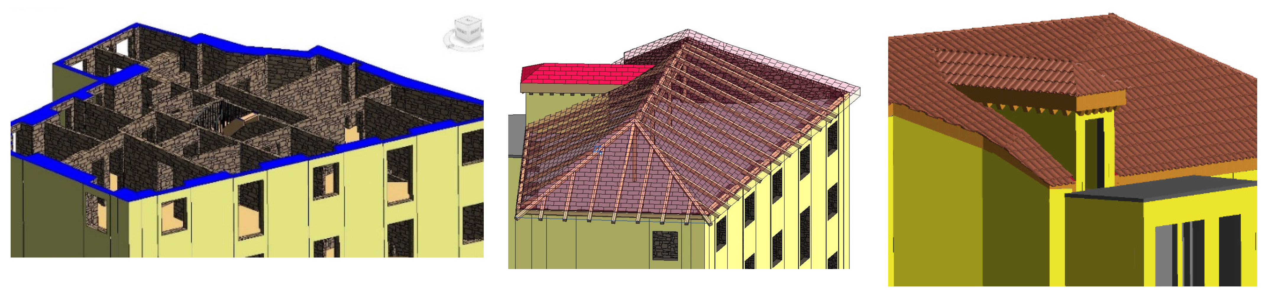
4.1. Modeling of the Façade to Be Preserved and the New Elements to Be Built

The model of the façade was created in Revit based on the technical drawings provided by the owners of the reconstruction project. First, a set of levels were defined corresponding to each existing floor. Due to the specific geometry of the building walls, with distinct thickness, no adequate parametric objects were available in the software library. An alternative modeling process was applied. For this purpose, the Model in Place command was used, allowing the modeling of the walls through the Extrusion function, from an outline representing the walls in the plan. The selected material was a masonry type referred to as stone-cypress, allowing the facades of the building to be represented with realism, partially demolished (Figure 4).
The voids, corresponding to the places where the windows and door were positioned, were created with the Void Forms function. A second extrusion with an offset of 5 mm was applied for the generation of the finishing layer of the façade walls, being the material considered for plastering. After, a painting function was considered (Figure 5).
To complete the architectural model, the interior walls and the roof were represented using directly the objects available in Revit library (Figure 6). The resulting model represented, with a great rigor, the antique building before and after the demolition of the interior components (walls and floors).

4.2. Modeling the Context of the Construction Site

The construction site elements, relevant to representing the context of the construction site, were also modeled, completing the architectural BIM model presented in Figure 7. This representation supports the analyses of several logistics and construction site activities impacting on occupational safety, namely the circulation of construction workers and equipment, and the loading and unloading materials, enabling the analyses of the available space and the identification of important constraints.

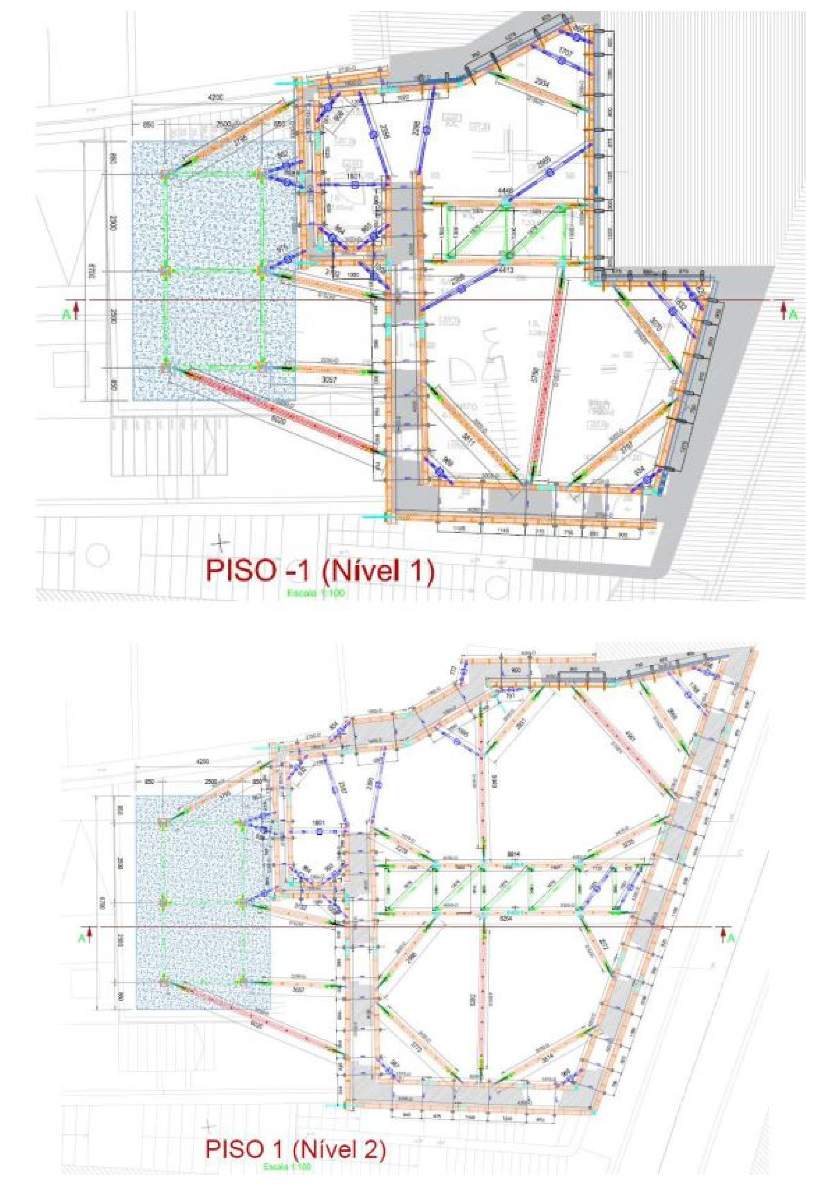
4.3. Model of the Temporary Steel Structural System

The temporary support system was a steel SHORFLEX HD framework, with an additional exterior vertical frame [35]. The modeling process of this system was based on the technical specifications document of the constructor. The system is composed by metallic elements assembled both in the interior and exterior of the building for the purpose of temporarily supporting the façade walls, after the demolition of existing structural elements in the interior of the old building and before the erection of the new elements in which the existing façade will be incorporated. All the connections that form the system are bolted, allowing the system to be reused and eliminating the need for welding.

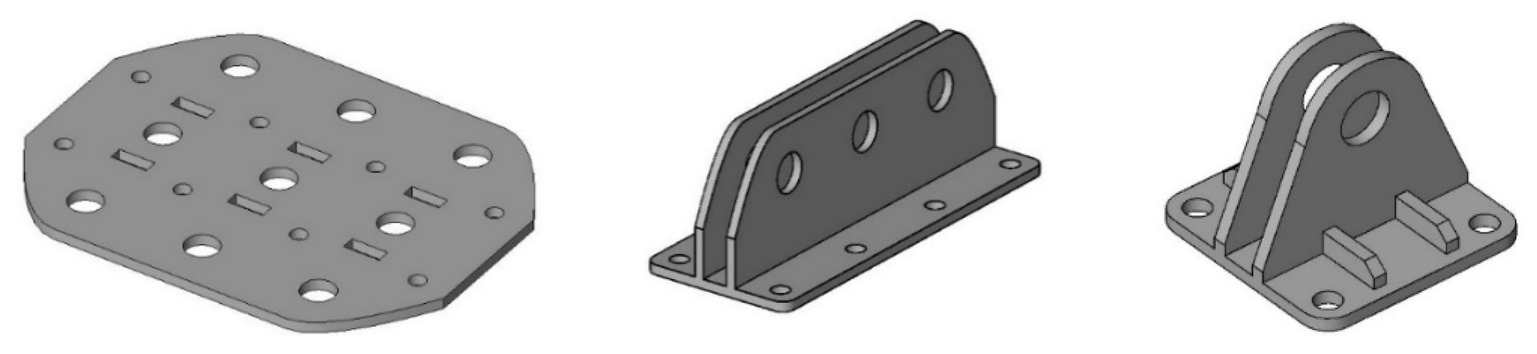
4.3.1. Modeling the Components

As the system presents a specific geometry and details, Revit does not contain any library with the required parametric objects. Therefore, it was necessary to model each element and, after, insert them adequately in the model composing the entire system. Thus, several new objects were modeled using the family creation system of Revit. The central component of the system is C-shaped steel bars, as shown in Figure 8.
The remaining components were modeled using specific functions (Figure 9): the horizontal and diagonal beams, with the beams and braces option; the steel connectors and several bolts, using a face-based template; the steel components of the foundation, with the structural foundation function applied. The components were assembled forming complex structures (Figure 10).

4.3.2. Assembling the Temporary Support System

Following the planned strategy of positioning the support system represented in the available technical drawings, a 3D model of the steel framework was composed (Figure 11).
As the present study was developed alongside the real work of demolition and the position of the façade containment, several photographs were taken in the place, allowing comparison of the model and the construction site (Figure 12).

4.4. Modeling of the Tower Crane

In order to support the demolition process and the insertion of the temporary support system, a tower crane was used. The tower crane was modeled based on its location in the actual construction site. First, an opening was created along all the levels, using the Shaft Opening function of Revit (Figure 13). The model of the tower crane was downloaded from the ReviCity website [36] and adapted to the exact configuration. This site offers a large variety of Revit objects, saving considerable time in modeling projects.

5. Modeling of the Construction Works (4D BIM)

The sequencing of construction activities and the project schedule was established using the Microsoft Project (MS Project) software [37]. First, a survey of the physical conditions of the building was carried out. The analysis allowed the identification of the constraints of the construction and the necessary activities required in line with the objective of the rehabilitation project, which includes demolition, preservation of the façade walls, and the building remodeling. In parallel, a risk identification process was implemented to detect occupational safety issues that need to be addressed.

5.1. Construction Site Constraints and Preparatory Activities

The rehabilitation project occurred in a neighborhood in Lisbon in a very narrow street. This lack of space impacted the circulation of workers and the storage of materials and forced the tower crane to be installed inside the area associated with the building. The preparatory activities required included:
  • Removal of the roof—The roof tiles contained asbestos, which is a very hazardous material to the health of workers in the building, meaning that this activity took precedence above the others;
  • Implementation of the tower crane—This process was accomplished with the assistance of an additional mobile crane and demanded temporary shafts to be created inside the building (Figure 14);
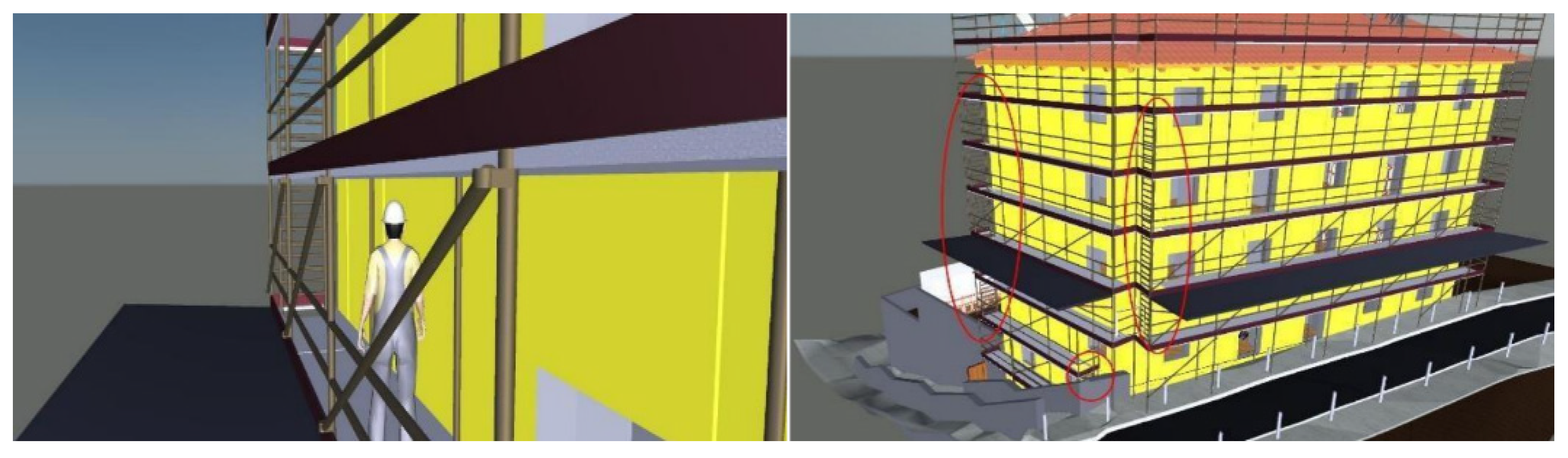
  • Temporary support of façade and scaffolding—Due to a lack of space in the public street, the support system for the façade walls was implemented inside the building and in the backyard (Figure 11 and Figure 12) with the aid of the tower crane (Figure 13). The modeling allowed for early identification of clashes with temporary scaffolding and enabled the early preparation of alternatives to be considered (Figure 15);
  • Demolition—In the interior part of the building, some of the walls were first demolished. Due to the age of the building, and the traditional materials applied, intensive manual labor was involved in the demolition work. Once the support system was fully positioned over the façade walls, the demolition process started from top to bottom. However, the positioning of the façade system required the demolition of the interior walls of floors −1, 1, and 3;
  • Construction works—Once the interior of the building was fully demolished, with only the façade walls remaining, the construction works begun, progressing from bottom to top and starting at the −2 floor;
  • Removal of the support system—The removal was executed in a phased way, occurring in tandem with the construction works.

5.2. Hazards and Occupational Safety

The safety hazard assessment is an important activity for the occupational health and safety of workers at the construction site [38]. On the construction workplace, the following potential hazards were identified:
  • Fall from height;
  • Exposure to chemical and biological hazards;
  • Crushing and other hazards exposure in the assembly and/or removal of structural elements (e.g., façade support system).
Every time a safety hazard cannot be eliminated at the source, it is necessary to implement measures that mitigate that hazard. These safety measures are divided in two categories: collective and individual protective measures. The collective measures include:
  • Implementation of guardrails where falls can eventually occur with a high possibility;
  • Protection of floor openings (Figure 14);
  • Correct use of ladders, as these must be properly fixed and be in good conditions.
When collective measures are insufficient to mitigate risk, individual protection measures must be implemented. These include individual protection equipment and are divided into two groups regarding their utilization:
  • The permanent protection devices must always be used when a worker is at the construction site (e.g., helmet, steel toe boots, vests, and gloves);
  • The temporary protection equipment is used when manipulating specific materials or machinery (e.g., goggles, earplugs, and masks).
The occupational risk analysis was undertaken together with the consultation of the Health and Safety File of the rehabilitation project, provided by the constructor.

6. Modeling of Occupational Safety Coordination in Construction (8D BIM)

The next step concerns the coordination phase of the project. In this phase, a clash detection test and several simulations regarding the project logistics were performed using the Navisworks software.

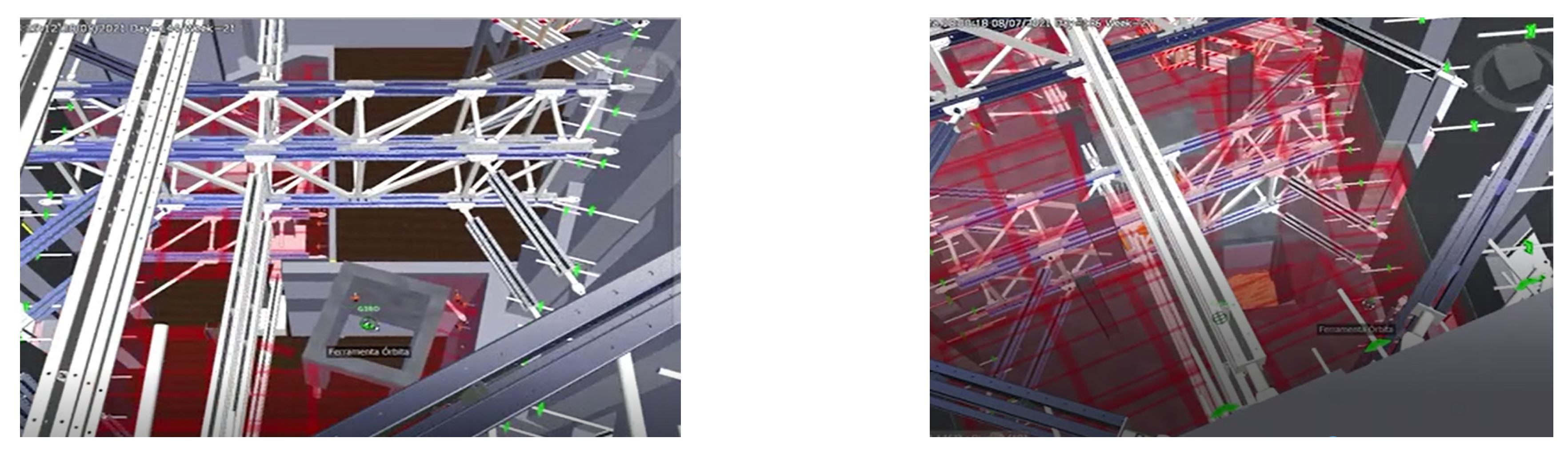
6.1. Clash Detection

To perform a clash detection test in Navisworks, the models created in Revit were transferred to this BIM visualizer. Over the transferred model, distinct sets of components were created. Each set associates several objects of the model according to the corresponding construction activity. The sets can be updated manually (selection sets) or based on parametric conditions (search sets). In the present case, two types of sets of objects were created:
  • Belonging to the architecture model;
  • Belonging to the temporary support system of the façade walls;
  • Belonging to other temporary elements in the construction site.
In Navisworks, the Clash Detective function was used to identify inconsistencies between elements of the two models. The clash between two objects with a geometric conflict was then shown with distinct colors (Figure 15 and Figure 16).
The identified conflicts were divided in two types:
  • The inconsistencies that can be resolved and approved by the Navisworks user (such as expected conflicts as the placement of the steel beam that secures the support system to the façade walls, or small geometric imprecisions that occurred during the modeling);
  • The collisions that require being remodeled in Revit, and after a new test must be applied.

6.2. Safety Prevention

Once the conflicts resulting from the clash detection were resolved, visual simulations of the construction site and its activities were performed. This allows an improved understanding of the construction work and improves the communication between the designer team and the construction team and, thus, with the workers that will perform the tasks. In addition, Navisworks allows the incorporation of an avatar for a better comprehension of the dimension and scale of the construction, and the required logistics. In this case, an avatar of a construction worker 170 m tall was selected. The hazard analyses and the proposal save barrier composed the 8D BIM model. The avatar was selected according to a taller worker, in a Portuguese context. The study presents just one case. However, in other projects, the tall avatar selection should be understood in a national industry context.
Furthermore, the simulations were focused on possible safety hazards and possible measures to combat those dangers. An avatar walking through the construction place can perform the simulation of eventual exposures. Mitigation measures can, thus, be selected and implemented. Examples of preventive actions resulting from this process:
  • The first performed simulation concerns the accesses to the construction site. There are two possible entrances, a front entrance and a small adjacent one on the side of the building. The front entrance is located on a narrow street with a very small sidewalk, and to prevent the fall of an object, an upper barrier integrated with the scaffolding was proposed (Figure 17);
  • Additionally, there is a possibility of accidents occurring due to the fall of objects onto the sidewalk. For this purpose, scaffolding with safety guards was placed above the sidewalks (Figure 18);
  • The side entrance also demonstrates the lack of space and requires a barrier in order to limit access to the site. For this purpose, a door was placed (Figure 19).
  • In the interior of the building, the position of guardrails can be studied over the model (Figure 14 and Figure 20).
Figure 18. Circulation path over a scaffolding.
Applsci 12 10577 g018
Figure 19. Limit access to the site with a door.
Applsci 12 10577 g019
Figure 20. Study of a guardrail location.
Applsci 12 10577 g020
The study of the movement of the steel elements raised to each level can be analyzed over the model, supported by the walkthrough allowed by an avatar and the modeling of a suspended platform (Figure 21). This also enables the impact of the positioning of the platform and limitations of access due to the location of the openings in the façade or installed equipment (Figure 22).
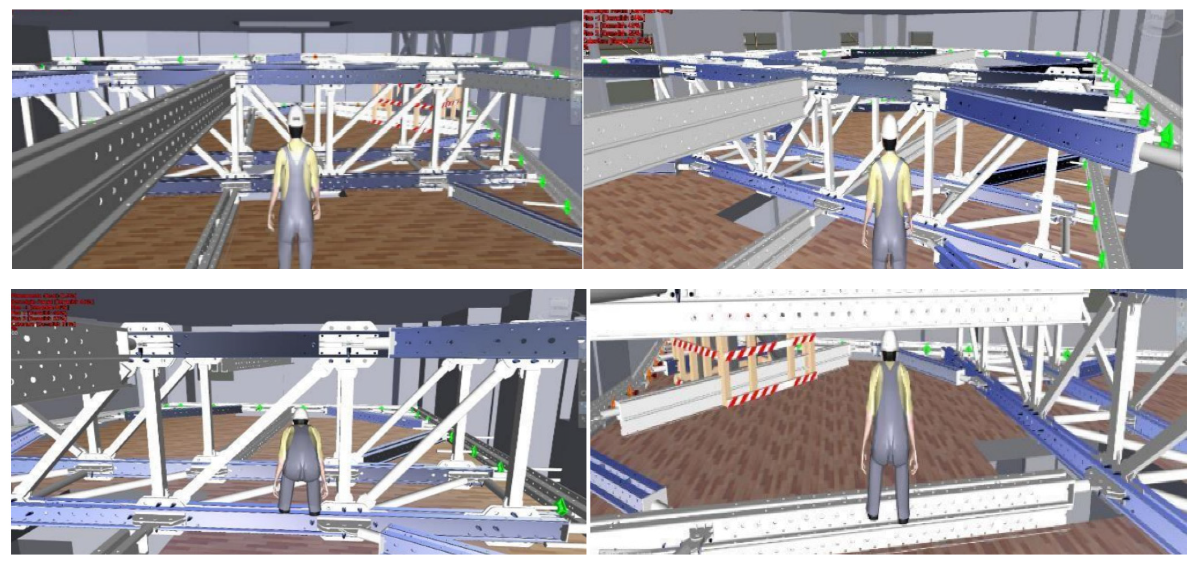
  • In relation to the interior of the construction, the structure of the containment system occupies a large amount of space inside each floor, significantly conditioning the work resulting in the area. An avatar moving inside the place illustrates the worker’s difficulties in operating inside the building (Figure 23).

6.3. Planning and Sequencing Activities

The organization of the construction activities was made using the Work Breakdown Structure (WBS) technique combined with scheduling methods and MS Project software. The duration of each construction task is defined using a deterministic approach, meaning that a task has only one fixed duration. The relations between tasks used are of the following types: Finish-to-Start (FS); Start to-Start (SS); Finish-to-Finish (FF).
Thus, a Critical Path Method was employed to determine a theoretical early start time and an early finish time to each task. This allows the determination of the critical path, which consists in the sequence of tasks that correspond to the minimum duration of the construction project.

6.4. Construction Simulation

For the simulation of the construction activity, the Timeliner function, accessed in the Navisworks, was applied. This application allows the creation of a 4D model through the link of the planning map and the 3D model of the building. This functionality establishes the required link between sets and activities, correspondingly obtained by Revit and MS Project software.
This involved some preparatory activities, both in Revit 2022 and MS Project 2022 software. A parameter entry was added to the objects of both models, the architecture and the temporary elements. The value of the parameter must identify the construction activity that the object is related to. This entry must contain the same name as the activity, listed in the MS Project file. After, the file was exported to Navisworks and the Search Sets function was then applied. This selection of elements, in order to compose sets, was made based on the name of the distinct activities, resulting in sets identified by the respective activity. Using the run command, it is possible to visualize the simulation of the insertion process step by step (Figure 24). In addition, each set was associated to a type of task: demolish, construct, and temporary. These types determine the visibility of the objects during the running of the Timeliner simulation and the final presentation after a task is completed. A video was added to the present paper (mp4 file—Video construction simulation in Supplementary Material).

7. Conclusions

The BIM methodology is a current innovate approach associated with a wide variety of tools that enable the discovery of new strategies of presenting and studying specific construction sectors. BIM has been used in the development of projects, based on the centralization of information, and, thus, several partial models or complementary components can be created and positioned over in order to analyze the operation concerning several parts working together.
The present study is focused on the elaboration of an 8D BIM work applied in a building heritage case, namely concerning the analyses of the safety risks in the temporary support of a façade to be preserved. For that, two BIM models were created, representing definitive and temporary elements, plus an avatar walkthrough was performed. This perspective is a pioneer in the development of rehabilitation projects and was designed to answer the following research question of this study: can 8D BIM be used in urban rehabilitation projects to enhance the occupational safety of temporary construction works? The results of the study showed that 8D BIM allows for early pre-construction risk mitigation and increased awareness of occupation safety and health issues.
The study involved the use of Revit, for the modeling purpose; the MS Project to model the sequencing and scheduling of construction activities; Navisworks, a BIM visualizer, to verify clash detections, to visually simulate the construction process, and to alert the eventual situations of hazards:
  • Operating Revit software, a precise and detailed 3D model of the project was built, and this was accomplished by using existing objects in the Revit library and through the family creation system;
  • A clash detection text was performed; some existing conflicts were resolved by using the Navisworks software and the others that needed to be remodeled were in Revit;
  • The scheduling plan of the construction project was performed swiftly and efficiently with the support of MS Project. Once the conflicts were resolved, several simulations of the construction site and its activities were conducted;
  • Through the visual simulation performed in the system by the insertion of an avatar walking inside, several situations of eventual hazards were identified. Adequate solutions were then proposed, namely in the entrances to the construction site or a worker moving inside the still frame. There were several identified constraints and hazards associated with them, and safety measures were proposed accordingly.
The coordination phase of the methodology was conducted via Navisworks. The simulation of the activities was made possible by combining the 3D model of the project with the planning file, thus establishing the interoperability between the two programs and proving the feasibility of the methodology.
The main limitations of the simulations involved in the empirical case study do not cover quantitative analysis (e.g., mitigation of occupation safety risk levels) that would enable the detailing of how specific safety management practices deriving from the BIM 8D methodology applied to temporary works in renovations projects may impact occupational safety performance. However, the study demonstrates that there are potential advantages that can be realized with the applications of BIM in this context.

Supplementary Materials

The following supporting information can be downloaded at: https://www.mdpi.com/article/10.3390/app122010577/s1, mp4 file—Video construction simulation.

Author Contributions

Conceptualization, N.M.A. and A.Z.S.; methodology, A.Z.S.; software, G.B.C.; validation, G.B.C.; formal analysis, A.Z.S.; investigation, G.B.C.; resources, N.M.A.; data curation, N.M.A.; writing—original draft preparation, A.Z.S. and G.B.C.; writing—review and editing, A.Z.S. and N.M.A.; visualization, N.M.A.; supervision, N.M.A. and A.Z.S. All authors have read and agreed to the published version of the manuscript.

Funding

This work is funded by national funds through FCT—Foundation for Science and Technology, I.P., under the research center CERIS—Civil Engineering Research and Innovation for Sustainability, Lisbon, Portugal.

Institutional Review Board Statement

Not applicable.

Informed Consent Statement

Not applicable.

Data Availability Statement

The study is supported in the MSc dissertation of Constantino, G.B., BIM 8D Model: Application for temporary support system of facades, Department of Civil Engineering, University of Lisbon, Lisbon, Portugal, 2021. With the institutional link: https://fenix.tecnico.ulisboa.pt/teacher/thesisDocumentConfirmation.do?thesisID=565303595503566&method=viewThesis&_request_checksum_=6121493cc2247448dd003be602e5d4b1fc4b177b (accessed on 1 September 2022).

Conflicts of Interest

The authors declare no conflict of interest.

References

  1. Barbosa, F.; Woetzel, J.; Mischke, J.; Ribeirinho, M.J.; Matthew, S.; Bertram, N.; Brown, S. Reinventing Construction: A Route to Higher Productivity; McKinsey & Company, Chicago, USA: 2017. Available online: https://www.mckinsey.com/business-functions/operations/our-insights/reinventing-construction-through-a-productivity-revolution (accessed on 5 September 2022).
  2. Couto, J.P.; Teixeira, J.M.C. The consequences of non-compliance with deadlines for the competitiveness of the construction industry-reasons for delays. In Proceedings of the 3rd Conference in Enginnering, Covilha, Portugal, 5–8 December 2005; Available online: https://hdl.handle.net/1822/5068 (accessed on 1 September 2022).
  3. Klein, H.C.; Stelter, A.; Oschinsky, F.M.; Niehaves, B. A status quo bias perspective on user resistance in building information modeling adoption–Towards a taxonomy. Comput. Ind. 2022, 143, 103760. [Google Scholar] [CrossRef]
  4. Zhao, Y.; Taib, N. Cloud-based Building Information Modelling (Cloud-BIM): Systematic literature review and Bibliometric-qualitative Analysis. Autom. Constr. 2022, 142, 104468. [Google Scholar] [CrossRef]
  5. Zheng, X.; Lu, Y.; Li, Y.; Le, Y.; Xiao, J. Quantifying and visualizing value exchanges in building information modelling (BIM) projects. Autom. Constr. 2019, 99, 91–108. [Google Scholar] [CrossRef]
  6. Deng, M.; Wang, X.; Li, D.; Menassa, C.C. Digital ID framework for human-centric monitoring and control of smart buildings. Build. Simul. 2022, 15, 1709–1728. [Google Scholar] [CrossRef]
  7. Setaki, F.; Timmeren, A. Disruptive technologies for a circular building industry. Build. Environ. 2022, 223, 103394. [Google Scholar] [CrossRef]
  8. Wang, W.; Guo, H.; Li, X.; Tang, S.; Li, Y.; Xie, L.; Lv, Z. BIM Information Integration Based VR Modeling in Digital Twins in Industry 5.0. J. Ind. Inf. Integr. 2022, 28, 100351. [Google Scholar] [CrossRef]
  9. Tran, S.V.-T.; Nguyen, T.L.; Chi, H.-L.; Lee, D.; Park, C. Generative planning for construction safety surveillance camera installation in 4D BIM environment. Autom. Constr. 2022, 134, 104103. [Google Scholar] [CrossRef]
  10. Akbal, E.; Tuncer, T. A learning model for automated construction site monitoring using ambient sounds. Autom. Constr. 2022, 134, 104094. [Google Scholar] [CrossRef]
  11. Sousa, H.; Sguazzo, C.; Cabaleiro, M. Use of BIM in rehabilitation and assessment of the built heritage, In Proceedings of the IABSE Symposium 2019 Guimarães: Towards a Resilient Built Environment-Risk and Asset Management, Guimarães, Portugal, 27–29 March 2019. [CrossRef]
  12. Bacci, G.; Bertolini, F.; Bevilacqua, M.G.; Caroti, G.; Martínez-Espejo, I.; Martino, M.; Piemonte, A. HBIM methodologies for the architectural restoration. The case of the ex-church of San Quirico All’olivo in Lucca, Tuscany. Int. Arch. Photogramm. Remote Sens. Spatial Inf. Sci. 2019, XLII-2/W11, 121–126. [Google Scholar] [CrossRef] [Green Version]
  13. Cuartero, J.; Cabaleiro, M.; Sousa, H.S.; Branco, J.M. Tri-dimensional parametric model for prediction of structural safety of existing timber roofs using laser scanner and drilling resistance tests. Eng. Struct. 2019, 185, 58–67. [Google Scholar] [CrossRef]
  14. García-Valldecabres, J.; Galiano-Garrigós, A.; Meseguer, L.C.; López-González, M.C. HBIM work methodology applied to preventive maintenance: A state-of-the-art review. In Building Information Modelling (BIM) in Design, Construction and Operations IV; WIT Transactions on The Built Environment; WIT Press: Santiago de Compostela, Spain, 2021; Volume 205, Available online: https://www.witpress.com/elibrary/wit-transactions-on-the-built-environment/205/38170 (accessed on 1 September 2022).
  15. Manjia, M.B.; Merveilles, U.J.; Pettang, N.; Ouambo, P.; Fandjio, C.C.; Abanda, F.H.; Pettang, C. Integration and impact of BIM in the rehabilitation of buildings in developing countries. J. Decis. Syst. 2022, 1. [Google Scholar] [CrossRef]
  16. Sola-Caraballo, J.; Rincón-Calderón, J.M.; Rivera-Gómez, C.; López-Martínez, J.A.; Galán-Marín, C. On-Site Risk Assessment Methodology of Historic Timber Structures: The Case Study of Santa Cruz Church. Buildings 2022, 12, 935. [Google Scholar] [CrossRef]
  17. Vidovszky, I. Impact-based Diagnostic Approach for Maintenance Monitoring of Historic Buildings. Procedia Eng. 2016, 164, 575–582. [Google Scholar] [CrossRef]
  18. Moyano, J.; Gil-Arizón, I.; Nieto-Julián, J.E.; Marín-García, D. Analysis and management of structural deformations through parametric models and HBIM workflow in architectural heritage. J. Build. Eng. 2022, 45, 103274. [Google Scholar] [CrossRef]
  19. Croce, P.; Landi, F.; Puccini, B.; Martino, M.; Maneo, A. Parametric HBIM Procedure for the Structural Evaluation of Heritage Masonry Buildings. Buildings 2022, 12, 194. [Google Scholar] [CrossRef]
  20. Croce, V.; Caroti, G.; De Luca, L.; Jacquot, K.; Piemonte, A.; Véron, P. From the Semantic Point Cloud to Heritage-Building Information Modeling: A Semiautomatic Approach Exploiting Machine Learning. Remote Sens. 2021, 13, 461. [Google Scholar] [CrossRef]
  21. Gilmour, L.; Stroulia, E. Ortho-photogrammetry for prefabricated energy-efficiency retrofits. Autom. Constr. 2022, 134, 104082. [Google Scholar] [CrossRef]
  22. Sacks, R.; Eastman, C.M.; Teicholz, P.; Lee, G. BIM Handbook: A Guide to Building Information Modeling for Owners, Designers, Engineers, Contractors, and Facility Managers, 3rd ed.; John Wiley & Sons, Inc.: Hoboken, NJ, USA, 2018; p. 688. ISBN 978-1-119-28755. [Google Scholar]
  23. Eastman, C. An outline of the building description system. Institute of Physical Planning, Carnegie-Mellon University Pittsburgh, USA, Pa. Inst. of Physical Planning. Research Report No. 50. September 1974, Computer Science, 23pgs. Available online: https://files.eric.ed.gov/fulltext/ED113833.pdf (accessed on 5 September 2022).
  24. Sampaio, A.Z.; Gomes, A.M. Professional one-day training course in BIM: A practice overview of multi-applicability in Construction. J. Softw. Eng. Appl. 2022, 15, 131–149. [Google Scholar] [CrossRef]
  25. Constantino, G.B. BIM 8D Model: Application for Temporary Support System of Facades. Master’s Thesis, Department of Civil Engineering, University of Lisbon, Lisbon, Portugal, 2021. [Google Scholar]
  26. Nederveen, G.A.; Tolman, F.P. Modelling multiple views on buildings, Automation in Construction. ScienceDirect 1992, 1, 215–224. [Google Scholar]
  27. Succar, B. Building Information Modelling Maturity Matrix. In Handbook of Research on Building Information Modelling and Construction Informatics: Concepts and Technologies; Underwood, J., Isikdag, U., Eds.; Information Science Reference; IGI Publishing: Hershey, PA, USA, 2010. [Google Scholar] [CrossRef]
  28. Gomes, N.R. Analysis of BIM Technology Capabilities in the Generation of 4D Models. Master’s Thesis, Department of Civil Engineering, University of Lisbon, Lisbon, Portugal, 2022. [Google Scholar]
  29. Han, K.K.; Golparvar-Fard, M. Appearance-based material classification for monitoring of operation-level construction progress using 4D BIM and site photologs. Autom. Constr. 2015, 53, 44–57. [Google Scholar] [CrossRef]
  30. Sampaio, A.Z. Maturity of BIM Implementation in the Construction Industry: Governmental Policies. Int. J. Eng. Trends Technol. 2021, 69, 92–100. [Google Scholar] [CrossRef]
  31. Kamardeen, I. Knowledge-based occupational health and safety planning for construction projects. In Proceedings of the 26th Annual ARCOM Conference, Leeds, UK, 6–8 September 2010; Egbu, C., Ed.; Association of Researchers in Construction Management: Reading, UK, 2010; Volume 1, pp. 271–280. Available online: http://www.arcom.ac.uk/-docs/proceedings/ar2010-0271-0280_Kamardeen.pdf (accessed on 1 September 2022).
  32. Farooqui, R.U.; Ahmed, S.M.; Azhar, N. Designing for construction safety: A construction management approach. In Proceedings of the Conference CIB W70 Conference in Facilities Management, Facilities, Emerald Group Publishing Limited, Cape Town, South Africa, 17–19 June 2007; Available online: https://www.irbnet.de/daten/iconda/CIB10269.pdf (accessed on 1 September 2022).
  33. Baker, G.; Barsotti, A. In Procurement Methods to Facilitate Designing for Safety and Health. Designing for Safety and Health in Construction. 2007. Available online: https://www.hse.gov.uk/waste/services/assets/esa-contractor.pdf (accessed on 1 September 2022).
  34. Vieira, M.C. History of Architectural Typologies of Current Housing, Built in the City of lisbon from the Early 18th Century to the 1930s. Ph.D. Thesis, University Institute of Lisbon, Lisbon, Portugal, 2018. Available online: http://hdl.handle.net/10071/18809 (accessed on 1 September 2022).
  35. Shorflex-hd. Available online: https://www.metalusa.co.uk/product/shorflex-hdcontainment-system/ (accessed on 1 July 2022).
  36. RevitCity.com. Available online: https://www.revitcity.com/index.php (accessed on 1 July 2022).
  37. Microsoft Project. Available online: https://www.microsoft.com/en-en/microsoft-365/project/project-management-software (accessed on 1 July 2022).
  38. Lyon, B.K.; Popov, G.; Biddle, E. Prevention through design: For hazards in construction. Prof. Saf. 2016, 61, 37–44. Available online: https://aeasseincludes.assp.org/professionalsafety/pastissues/061/09/F2_0916.pdf (accessed on 1 September 2022).
Figure 1. Scheme of the software used.
Applsci 12 10577 g001
Figure 2. Localization of the case study (from Google Maps).
Applsci 12 10577 g002
Figure 3. CAD drawings of the project.
Applsci 12 10577 g003aApplsci 12 10577 g003b
Figure 4. 3D representation of the walls in floor 0 and selection of the material (stone-cypress).
Applsci 12 10577 g004
Figure 5. Model of the façade walls.
Applsci 12 10577 g005
Figure 6. Model of the interior walls and roof.
Applsci 12 10577 g006
Figure 7. Complete architectural model and surrounding elements.
Applsci 12 10577 g007
Figure 8. Components based in C-shaped steel beam.
Applsci 12 10577 g008
Figure 9. Components based in a face-based template.
Applsci 12 10577 g009
Figure 10. Assembled components.
Applsci 12 10577 g010
Figure 11. Plan showing the position of the temporary structural elements and details of the 3D model.
Applsci 12 10577 g011
Figure 12. Comparison of the BIM model with the real construction work.
Applsci 12 10577 g012
Figure 13. Definition of openings, insertion of the tower crane, and the real equipment in place.
Applsci 12 10577 g013
Figure 14. Insertion of the tower crane and guardrails for fall protection in temporary shafts.
Applsci 12 10577 g014
Figure 15. Clash test of temporary scaffolding and temporary support structure.
Applsci 12 10577 g015
Figure 16. Results from the clash detection test.
Applsci 12 10577 g016
Figure 17. Hazard mitigation in the front entrance of the construction site.
Applsci 12 10577 g017
Figure 21. Simulation of hazard by crushing and suggestion of a steel beam movement.
Applsci 12 10577 g021
Figure 22. Analysis of suspended platform.
Applsci 12 10577 g022
Figure 23. Operations inside the building while temporary support structure is in place.
Applsci 12 10577 g023
Figure 24. Simulation of construction progress of definitive and temporary elements.
Applsci 12 10577 g024aApplsci 12 10577 g024b
Publisher’s Note: MDPI stays neutral with regard to jurisdictional claims in published maps and institutional affiliations.

