1. Introduction
The capturing of non-cooperative targets in orbit is still a difficult task for on-orbit missions because of its theoretical challenge as well as practical significance; the compliant contact between the spacecraft-manipulator system and space targets belongs to the vital problems of capture task [
1]. A spacecraft-manipulator system is composed of a three-dimensional base (a spacecraft) and an onboard manipulator, and the contact occurs during the end effectors’ interaction with the capture target where big contact force can be exerted.
To solve this problem, compliant control strategies dealing with non-cooperative objects have attracted substantial interest. The impedance controllers have demonstrated good performance in [
2,
3]. A latter paper [
4] used the disturbance observer to determine the contact force between the end joint and the spinning object, which is important for the impedance controller. In [
5], an impedance control strategy is used to buff the impact and to realize compliant capture operation. In paper [
6], researchers designed a coordination control to stabilize the space robot system based on impedance control, which is achieved with the parameter uncertainty of the model. Other efforts including coordinated motion control and contact model control have also been extensively studied [
7,
8,
9,
10,
11]. In [
12], the optimal impact control is employed to capture a space target with flexible dual-arm space robot. A novel coordinated control approach based on an adaptive algorithm for a free-floating flexible space robot is introduced in [
13]. In [
14], a capture method using the origami principle is proposed, which can capture various sizes objects without fixed contact points. In [
15], a novel capture area computing algorithm is discussed through establishing the evaluation equation of capture area existence. The control strategy based on contact model control is designed to capture the object on-orbit by estimating contact force between the gripper and the space object to achieve soft contact [
16,
17,
18].
The above research are all applied to rigid manipulators, and the interaction process is essentially a rigid contact. That is, there is no actual mechanical mechanism to output damping and spring forces to buffer the impact. Therefore, designing a new type of soft-docking mechanism to achieve compliant capture has become an effective means. In [
19], a flexible continuous robot endowed with a multi-cut mechanism is proposed to ensure the temperature control and compliant capture in the space environment. In [
20], a multidimensional damping mechanism with stiffness optimization is proposed to implant the momentum distribution and impact absorption during the on-orbit docking. A new type of topological polyhedron docking mechanism for space service is designed in [
21]. The paper [
22] designed a soft-capture arm with dual-mode to stabilize the attitude of the space robot. In [
23], a series-wound flexible capturing mechanism with multi-dimensional controllable damper is developed, and an optimization control was realized based on the particle swarm optimization. In [
24], a flexible net is employed as the capture mechanism which can quickly open or close, and the dynamics of flexible net are established to design the control method. A new adhesive capture mechanism is designed and the passive trigger mechanism is discussed in detail; contact-estimated modeling is proposed to take the failure of adhesive connection into account. The above studies demonstrate the superior performance of the soft-docking mechanism in dealing with the stabilization problem caused by contact forces during capturing.
The introduction of the soft-docking mechanism will increase the complexity of the modeling of the spacecraft-manipulator system, which requires accurate modeling of the flexible joint mechanism. In [
25], a dynamic model of the flexible robot is proposed by introducing the properties of friction in the flexible joints, and the characteristics of the planetary gear reducer are analyzed. The modeling and control problems of the spacecraft-manipulator system with flexible-link flexible-joint (FLFJ) introduced joint friction is studied based on the single direction recursive construction method and velocity variation principle in [
26]. The effect of friction, gear stiffness, and damping of the flexible joint is studied in [
27,
28,
29]. Liu et al. [
30] developed an autonomous mobile manipulator endowed with designed tandem elastic brake, and proposed a novel integral Lyapunov function to stabilize the robotic system under model uncertainty and external disturbance. The paper [
31] considered the unmodeled dynamics and dead zone problem in the stabilization control of the flexible-joint manipulator. In [
32], a new dynamic modeling of the special flexible robot consisting of prismatic joints is proposed, and the inverse dynamic is analyzed by a novel bisection-method-based algorithm. Other modeling methods for flexible joints are given in [
33,
34,
35,
36,
37]. Once an accurate model of the flexible joint introduced with soft-docking mechanism is obtained, the coordinated control strategy that integrates the flexible force output by the soft-docking mechanism and the active force of space robot system is possible to design in order to optimize the momentum distribution and impact absorption. In summary, the main contributions of this paper are as follows.
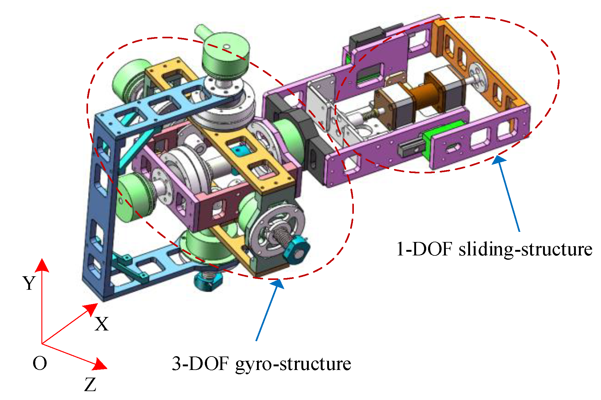
(1) A full-dimensional controllable damping mechanism (FDCDM) with gyroscopic structure is introduced into the joint of the space robot; the six-dimensional damping force outputs by the FDCDM is equivalented to the actuator outputs in the end joint.
(2) The whole-body dynamic model of SMS with full-dimensional damping mechanism is established using the Kane method. Furthermore, a contact force model combining the modified Hertz model and the LuGre friction model is used to estimate the contact force between the robot end-effector and the target without additional sensors.
(3) A backstepping integral sliding mode controller is proposed to optimize the momentum distribution and impact absorption. Additionally, the global asymptotic stability of the control system is guaranteed using the backstepping algorithm and Lyapunov theory.
(4) The results of numerical simulation experiments in ADAMS and MATLAB demonstrate the superior performance of the proposed approach.
2. Modeling of Spacecraft-Manipulator System with FDCDM
The full-dimensional controllable damping mechanism (FDCDM) with 4-DOF is shown in
Figure 1 [
20]. In this paper, the spacecraft-manipulator system is composed of a three-dimensional base (6-DOF) and 2-DOF onboard manipulator. Therefore, there will be 12-DOF for the spacecraft-manipulator system with FDCDM (SMS-FDCDM), as shown in
Figure 2.
2.1. Equivalent Kinematics Equation
The six-dimensional damping force outputs by the FDCDM can be equivalent to the actuator outputs in the end joint, as shown in
Figure 3. The relative linear velocities and angular velocities between adjacent rigid bodies
k and
k-1 are set as
and
(
k = 1, 2, 3, …, 7), respectively. Furthermore, the relative line displacement and angular displacement are set as
and
, respectively. We have:
where
denote the generalized velocity and
denote the generalized position.
Then, we can obtain the relative rotation matrix of the proprio-coordinate system in rigid bodies
k and (
k − 1) set as
is the ontology coordinate system in rigid bodies
k, and
denote the inertial coordinate system. Then, we have the absolute rotation matrix of
and
as
In this paper, the base proprio-coordinate system
is XYZ Euler angles
relative to the inertial coordinate system
, denote
. Then, we have the angular velocity of the base in the inertial frame
as
Then we have the kinematic equation of the model
where
where
denotes
and
denotes
.
Let
replace
, and
replace
; we have the kinematic equation of the system as
2.2. Partial Velocity Equation
The angular velocity of bodies
k in inertial coordinate system
is written as
The partial angular velocity is defined as
Substituting the (7) into (8), we can obtain the partial angular velocity
as
where
is the
jth column of
,
represents the identity matrix of
,
denotes the zero vector of
.
The position vector of the mass center of the rigid body
k in the inertial frame
is
where
denotes the position vector of the rigid bodies
k in the coordinate system
,
represents the centroid position vector of the rigid bodies
k in the coordinate system
.
Differentiating
in (10) with respect to time, we can obtain the velocity of the mass center of the rigid bodies
k in inertial system as
The partial linear velocity is defined as
Substituting the (11) into (12), we can obtain the partial angular velocity
as
where
is the
k-th row and the
l-th column of matrix
.
2.3. Dynamic Equations
Ignoring microgravity in space, the six-dimensional damping force outputs by the FDCDM on both sides of the
k-th rigid body can be obtained as
where
is the flexible torque acting on the right of rigid body
k;
is the stiffness parameter of the torsion spring on the right of rigid body
k;
is the damping parameter of the torsion spring on the right of rigid body
k;
is the flexible force acting on the right of rigid body 6;
is the stiffness parameter of the torsion spring on the right of rigid body 6; and
is the damping parameter of the torsion spring on the right of rigid body 6.
The equivalent active force
and the active torque of mass center of each rigid body
are:
where
represents the torque of base flywheel;
is the centroid position vector of the rigid body
i in the coordinate system
; and
and
are the impact force and torque acting on the end joint, respectively.
The equivalent inertia force
and the equivalent inertia torque
of rigid body
k can be expressed as
where
denotes the mass of rigid body
k, and
is the inertia tensor of rigid body
k.
denotes the angular acceleration of rigid body
k, and
is the centroid acceleration of rigid body
k.
In this paper, the spacecraft-manipulator system with FDCDM (SMS-FDCDM) can be equivalent to a tandem mechanism with 7 rigid body segments. Therefore, the generalized active force and generalized inertial force are set as
and
, respectively. Then, the Kane dynamic equations can be described by
where
;
.
Substituting (9), (13), (15), and (16) into (17), we can obtain the nonlinear ordinary differential equations of SMS-FDCDM system
where
2.4. Contact Force Model
All capture tasks require the robot to interact with space objects, where big impact forces can be exerted. To solve this problem, it is desirable to know the contact force in the whole capture process so that effective compliant control can be designed.
Currently, a lot of research indicate that the results of Hertz’s model are similar to those of actual contact tests at low speed. In this paper, a compound contact model combining an optimized Hertz’s model and a friction model is employed to estimate the contact force without additional sensors. The original Hertz’s model is established based on the theory of elasticity contact, which considers that there is no energy loss in the contact process; however, there are the following problems: at the beginning of the collision, the contact force is discontinuous, and at the end of the collision, the collision force makes the contact objects attract each other. So, it cannot accurately reflect the actual contact process.
Flores thinks that the energy loss in the contact process can be expressed as a function of the coefficient of restitution and the initial collision velocity of two contact objects. So, inspired by [
16], the Flores contact model based on the Hertz model and a hysteresis damping term can be written as:
where
is the contact stiffness coefficient,
is the penetration depth,
is the damping coefficient, and
is the relative impact velocity. Generally, the parameters
p and
q are set as
p = n and
q = 1, respectively.
The hysteresis damping factor
is designed as:
where
and
denote the restitution coefficient and the initial impact velocity, respectively.
When the grippers come into contact with the target surface, tangential friction will be generated. It is generally considered that the tangential friction is orthogonal to normal pressure and can be studied separately.
Because of the obvious advantages of the dynamic friction model compared with the static friction model, the dynamic friction model can describe the friction process more comprehensively. Among a variety of dynamic models, the LuGre friction model is a famous model in control research; it describes the Coulomb friction, pre-sliding, and Stribeck friction with first order differential equations, which can be described by [
38]
where
is the stiffness,
is the damping, and
is the stickiness.
is the relative velocity between contact surfaces.
denotes the Stribeck model.
is the coulomb friction force,
is the maximum static friction, and
is an empirical parameter which expresses the Stribeck speed.
In this section, the Flores model is employed to estimate the normal pressure, and the tangential friction is obtained by the LuGre model. Then, we can obtain the dynamic contact force between the manipulator and the target during capturing, so the precise stabilization control can be designed based on the dynamic contact model.
3. Design of the Coordinated Controller
According to
Section 2, the six-dimensional damping force outputs by the FDCDM are equivalented to the active flexible forces and torques in the end joint, so a coordinated controller is proposed to optimize the momentum distribution and impact absorption in
Section 3. The instantaneous impact may result in sudden change of base attitude, and the non-cooperative target increases the parameter uncertainty of the system. So, the design of the controller must have high robustness, high precision, and fast transient response. Let
denote the trajectory tracking error, where
denotes the desired trajectory. In order to obtain the above control performance, a backstepping nonsingular fast integral terminal sliding mode control (NFITSMC) is designed as:
where
,
are positive diagonal matrices,
p and
q are positive odd numbers satisfying the relation
, and
is designed as
In the case of , the second order derivative of yields . Although , but , so it does not cause singularity. When , the second order time derivative , note that , even , there is no singularity.
This design of can improve the problem of the convergence speed slowing down when the terminal attractor e is close to zero. Meanwhile, it can avoid the singularity problem. Therefore, the proposed sliding surface combines the advantages of the fast-sliding mode control and non-singular sliding mode control, giving the system features of fast finite-time convergence without the singular problem.
Define
is the finite time form
to
, and
is the finite time taken to travel from
to
, which is given by [
39]:
where
denote Gauss’ hypergeometric function.
According to (18) and (19), the time derivative of sliding surface
yields
where
,
,
and
denote the dynamic uncertainties and external disturbances.
For the convenience of writing, we define that
Then, a backstepping algorithm is used to find a control input which is effective for the stable of the space robot after capturing. The following change of coordinate is launched:
where
are the virtual control laws in the first and second steps, respectively.
Step 1: Differentiating
in (27) with respect to time, we can obtain
Therefore, a positive Lyapunov function is selected as
Differentiating
in (29) with respect to time yields
where
can be chosen as
.
is a positive design parameter.
Substituting (30) into (29) we can obtain
From (31), we can see that once .
Step 2: A virtual control input
is generated in this step which drives the variable
. Differentiating
in (27) with respect to time, we have
A Lyapunov function is choose as:
Differentiating
in (33) with respect to time, we have
Based on (34), the
is chosen as
. Substituting
into (34) obtains
From (35), can be obtained once is satisfied.
Step 3: This step we will contain the input torque
. The following Lyapunov function is defined
Differentiating
with respect to time, considering the results in (25) and (27), we have
Therefore, a backstepping NFITSMC (BNFITSMC) is designed as
where
,
is select as
,
is a positive small constant.
We can see that the includes the switching function; this switch item will produce the undesired chattering, so the saturation function is used to reduce chattering in simulation.
Substituting (38) into (37), we have
Then,
,
is negative semi definite; it implies that
,
,
will converge to zero in a finite time. Therefore, the terminal attractor
e will converge to zero in a finite time with the existence of uncertainties and disturbances. Additionally, the coordinated control combining the joint active torques and six-dimensional damping force is designed using the proposed BNFITSMC. The block diagram of the developed controller is illustrated in
Figure 4.
4. Numerical Simulation
In this paper, the characteristics of the collision process for the above SMS-FDCDM system are analyzed in the ADAMS workspace, and the vibration absorption of collision experiments performed in MATLAB environment. According to the whole-body model of SMS-FDCDM in
Section 2, the collision process can be simulated in ADAMS. The dynamic parameters of the SMS-FDCDM model are shown in
Table 1; the initial position of the end effector is [250, 250, 250] mm, and the target is set as a sphere with spin motion and initial velocity. The motion parameters of the target are shown in
Table 2, the collision parameters in Adams are shown in
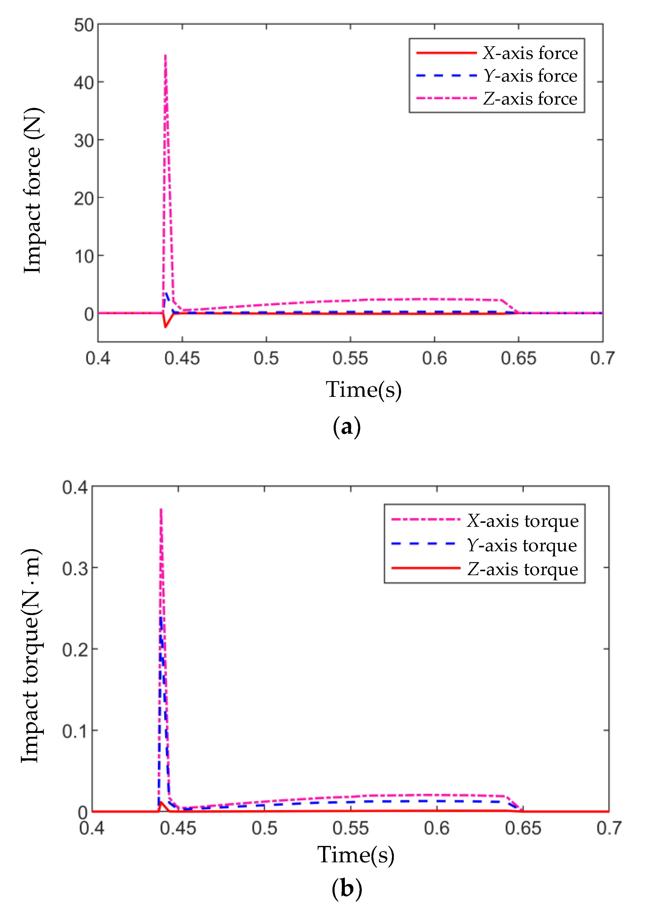
Table 3, and the impact force that occurs at the time of SMS-FDCDM contact with the space target is shown in
Figure 5.
From the results shown in
Figure 5, we can see that the maximum normal pressure is 45.2 N. The maximum impact torque is 0.38
. The duration is about 0.2 s, so the contact force is the impact force in a short time. The results obtained in ADMAS are used as input into MATLAB, and we can establish a MATLAB/Simulink-based simulation environment to verify the optimal results of coordinated control, which combine the quick non-singular integral terminal sliding mode control (NFITSMC) and FDCDM proposed in
Section 3.
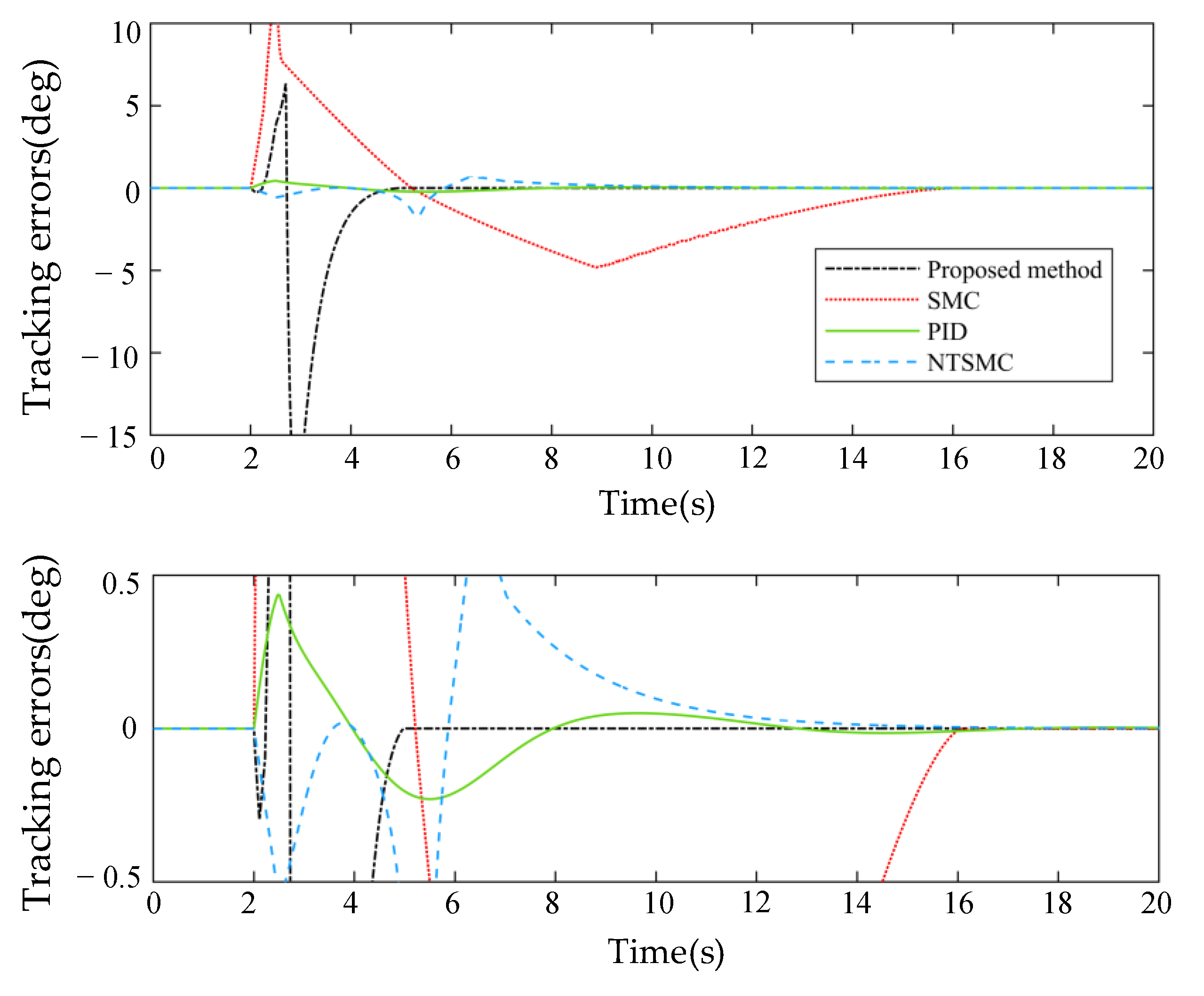
Without loss of generality, spatial 3-D cases have demonstrated to be a suitable platform to test control algorithms. Therefore, a 2-DOF manipulator and 4-DOF full-dimensional controllable damping mechanism (FDCDM) mounted on a free-floating (no position and attitude control) base (6-DOF) is used, which totals 12-DOF (6-DOF controllable) platform on spatial 3-D. A PID controller, traditional SMC, and a non-singular terminal sliding mode controller (NTSMC) are used as the comparison method in this paper. The selected parameters of the controller are reported in
Table 4. The contrast results are shown in
Figure 6 and
Figure 7.
Remark 1. In this part, the sliding surface of traditional SMC and NTSMC is and , respectively.
Remark 2. From
Table 4, we can see that the developed control input of BNFITSMC has many parameters such as
,
,
p,
q,
,
for the sliding surface and
,
,
for the backstepping gains; the selection of these parameters greatly affects the performance of the system. The parameters of sliding surface have been widely studied in many works, so these parameters are chosen based on experience from similar research and our experiments. However, studies on the combination of the backstepping method and SMC are limited. Therefore, the backstepping gains need to be effectively selected. In this paper, the backstepping gain parameters are chosen based on experiments. However, the values chosen based on the experiments are usually not optimal, so the design of a parameter optimization algorithm is necessary. This is also our research orientation in future works.
From
Figure 6 and
Figure 7, we can see that the PID controller performance was worse because of the largest steady-state error and the longest convergence time. The SMC and NTSMC both provide better performance compared with the PID with smaller steady-state error. However, it should be noted that the convergence of ABNFITSMC is obviously faster than SMC and NTSMC. In other words, the proposed method provides the best performance in terms of low steady-state error and fast convergence time.
It is assumed that the center of mass of a rigid body is at its geometric center; the base and joint are adjusted to initial posture
before the capture. Then, the space robot approaches the space target slowly, and the initial angular velocity of the base and each joint is 0, that is, only translational motion during the approach process. In order to reduce the chattering of the sliding surface in SMC, we replace symbolic function with saturation function. The impact forces and torques obtained in ADMAS are used as input for collision experiments in MATLAB, and the time of contact between the end effector (gripper) and the target is set at 2.2 s. The desired attitude of the stabilized system is
; the angle and angular velocity changes of the base and each joint with the NFITSMC after collision are shown in
Figure 8. The tracking errors of base and 2-DOF joints are shown as
Figure 9.
From
Figure 8, we can see the attitude of the base and 2-DOF joints converging to the desired pose in a short finite time. Furthermore, the angle velocity converging to zero ensures the system reaches steady state. The tracking errors of the base and 2-DOF joints are shown in
Figure 9, and they demonstrate the superior performance of the proposed method in terms of low steady-state error and fast convergence time.
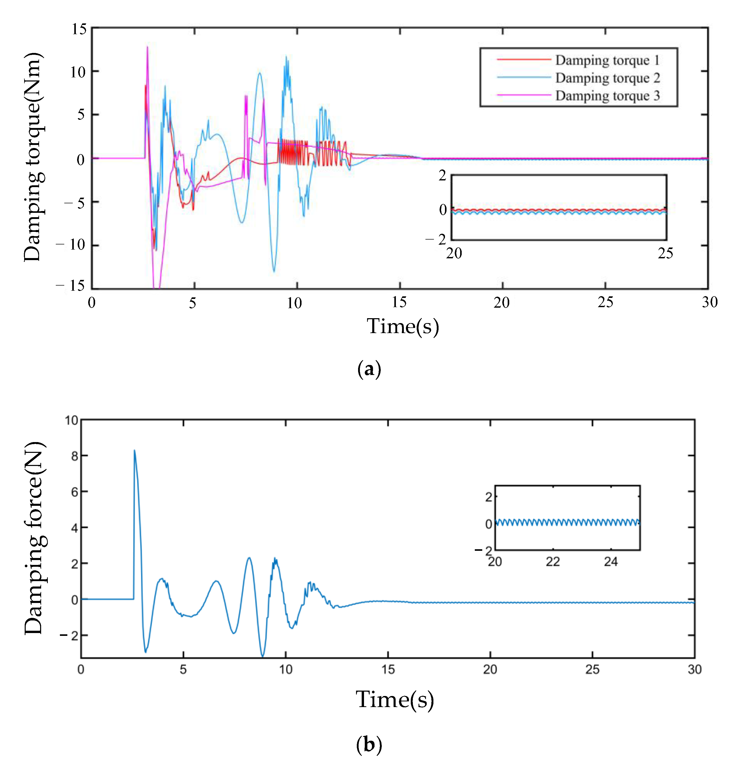
The damping torque outputs by the rotating damper of FDCDM are shown in
Figure 10 and the joint active torque of SMS are shown in
Figure 11. From
Figure 10 and
Figure 11, we can see that the proposed ABNFITSMC eliminates the chattering significantly, so the frequency and amplitude of the chattering is almost invisible, which results in the small steady-state error.
The results of
Figure 8,
Figure 9,
Figure 10 and
Figure 11 demonstrate that the full-dimensional damping mechanism and coordinated control system can greatly reduce the vibration caused by the contact force, and the attitude of SMS is quickly stabilized after capture using the proposed NFITSMC. From the above experimental results, we can conclude that the proposed BNFITSMC provides superior performance in terms of tracking accuracy, fast finite-time convergence, chattering elimination, and low steady-state error.
5. Conclusions
In this article, a full-dimensional controllable damping mechanism (FDCDM) with gyroscopic structure is introduced into the joint of the space robot, and the whole-body dynamic model of SMS with full-dimensional damping mechanism (SMS-FDCDM) is established using the Kane method. Then, we focus on the contact process during the capturing and the stabilization of the complex system after capturing non-cooperative space targets. Therefore, a novel backstepping non-singular fast integral terminal SMC (BNFITSMC) is proposed to optimize the momentum distribution and impact absorption. The impact force is buffered by six-dimensional force damping, and the disturbance to the system is greatly reduced, so the attitude of SMS is quickly stabilized after capture. The simulation results verify the advantages of the proposed method, such as (1) low steady-state error, (2) quick convergence time, (3) smooth control torque without chattering, and (4) robustness with uncertainties and disturbances. Therefore, the numerical simulation of collision experiment demonstrates the superior performance of the proposed approach. However, it should be noted that the introduction of this mechanism will make the joint become a variable stiffness joint. Therefore, stiffness estimation is necessary considering the controller, and the stiffness estimation usually requires accurate estimation of the flexible force. This will be the focus of our future research.


