Abstract
This study presents a new GFRP pipe structure fabricated by a combination of continuous and spacing arrangement of filament winding, where the latter was used to form the stiffened part and the former to form the structural part. Results of comparative analysis through a series of flatwise compression tests indicate that, with the same material consumptions, up to 38.7% increase in ring stiffness was achieved by the stiffened outer pipes with diameter of 400 mm, compared with the plain ones. The failure mode of this proposed pipe is ductile fracture during the loading process, and its bearing capacity did not decrease rapidly after fiber failure. The stiffened inner pipes with diameter of 500 mm exhibited an average of 16.7% increase in ring stiffness compared with the plain ones, while both types of specimens showed the same failure mode with delamination occurring between the stiffened layer and outer structural layer. From the experimental investigation, it is concluded that suitable geometric shape can significantly improve the ring stiffness of the specimens, which provides a guidance for structural design of pipelines and their geometric optimization.
1. Introduction
Fiber reinforced polymers (FRPs) have been extensively used as reinforcing and structural materials in industrial, chemical and civil infrastructure, due to their advantages of light weight, high strength, corrosion resistance, easy processing, design flexibility, etc. [1,2,3,4]. Nowadays, glass-fiber reinforced polymer (GFRP) pipelines buried underground are growing sharply in many industries (e.g., oil and gas, nuclear power, etc.) due to their outstanding properties, such as corrosion resistance, structural flexibility, lower weight to higher specific strength, higher moduli, excellent fatigue properties, and low installation costs [5,6,7,8]. GFRP pipe is a kind of thin-walled pipe. As mentioned in [9], the typical GFRP pipe has three layers, with GFRP composites forming the middle layer, namely the structural layer, to bear load. When the buried depth of a GFRP pipe exceeds 3.5 m, the pipe should be designed adequately rigid to withstand internal and external loads with minimum support from the side soil column [10]. The buried depth of the circulating water channel in a nuclear power plant is about 15 m. If the GFRP pipe is directly buried, the pipe stiffness (PS) needs to be exceptionally large, leading to a dramatic increase in the thickness of the pipeline and higher manufacturing costs. It is because thin GFRP layers can satisfy the required levels of pipe strength, but PS requirements necessitate employing thicker glass-fiber reinforced polyester (GRP) pipes [11]. Therefore, this paper aims to propose a light-weight design and low-cost manufacturing technique for buried composite pipelines, to enhance the PS to a level acceptable to GFRP pipe producers, with neither surplus strength nor a dramatic increase in project investment.
For buried or underground pipes, thick GRP mortar pipes are frequently utilized as an economical alternative, where a sand layer impregnated with resin is incorporated into the structural layers of GFRP pipes [11]. For instance, Rafiee and Habibagahi [12] inserted an additional layer, made of sand with unsaturated polyester resin, into the structural layer of a GFRP mortar pipe. Del Vecchio et al. [13] performed analysis on the plastic behavior and strain-rate sensitivity of cylindrical polymer mortar specimens. Another typical method has been to pour the reinforced concrete round the GFRP pipe withstanding the external dynamic and static loads, where the GFRP pipe is mainly used as the internal mold to bear the internal pressure of the system and the negative pressure of the pipeline is jointly borne by the GFRP pipe and the concrete trench. The above-mentioned combination modes are appropriate where the project investment is controlled within a reasonable range, but they bring several challenges. One major concern is delamination inclined to be induced into the composite-to-sand or composite-to-concrete interface [12,14,15], because of the different material properties. Thus, the pipe structure fails prematurely and finally loses load capability. Other concerns are the difficulties of expensive transportation and labor intensive installation, caused by the significant weight increase in the sand layer [16,17,18] or the reinforced concrete layer. To tackle these problems, pipe structures with light weight and improved concrete–GFRP interfacial bonding have captured increasing attention.
For instance, composite sandwiched structures consisting of stiff composite face sheets combined with core layers of light-weight materials have been proposed [19]. To further improve the stiffness of the core, extensive research has been made regarding the design, manufacturing, and mechanical evaluation of composite sandwiched structures with stiffened cores (e.g., lattice or corrugated structures) [20]. To name a few; Waqas et al. [21] compared different design configurations (e.g., CFRP and GFRP) used for the sandwich structure’s skin, and three different types of wood as core for composite bridges. Jin et al. [22] designed and fabricated a new integrated woven corrugated composite sandwich panel, which effectively prevented skin-to-core debonding. Fan et al. [23], Fan et al. [24], and Zheng et al. [25] designed and manufactured different integrated light-weight woven lattice panels and reported their failure mechanisms and excellent energy-absorption abilities. Zhu et al. [9] investigated a novel GFRP sandwiched pipeline structure with stiffened core, and results showed that the stiffness of the proposed pipe structure increased with considerable weight reduction. In general, many investigations focused on the mechanical behavior of FRP pipes subjected to internal hydrostatic, axial, or bending load [13,15,19,26,27,28,29]. However, lateral compression on buried pipelines should also be considered due to their working environment where the combined action of dead load (from the weight of the soil above the pipe) and live load (by vehicles traversing the pipeline on the surface) can arise [30]. Niknejad et al. [31], Rouzegar et al. [31], and Moeinifard et al. [32] carried out lateral crushing experiments to explore the energy absorption capacity of tubular structures. More recently, Sun et al. [33] and Li et al. [34] conducted comparative studies to investigate the lateral crushing behaviors of thin-walled aluminum, GFRP, and CFRP tubes. Despite its importance for facilitating light-weight design and manufacturing techniques for buried composite pipelines [9], the mechanical behavior of the GFRP structures under lateral compressive load has not received sufficient attention [35,36,37].
With the aim of further filling this knowledge gap, this study investigated a new GFRP pipeline structure with a stiffened layer to characterize its structural behavior under flatwise compression tests. Firstly, a complete explanation of the proposed pipe fabrication and testing methodology were established. Secondly, experimental and analytical studies were conducted to investigate the PS of the proposed pipe. Accordingly, the analytical and experimental results of PS are compared and discussed. In addition, the ring stiffness values of the commonly used pipes buried underground and the proposed pipes with different stiffened structures were measured in comparative experiments using the same materials. Furthermore, the deflections and buckling behaviors of various FRP pipes for different stiffened structures are described and discussed. The research showed that the stiffened tubes with rough surfaces had stronger interfacial bonding than the regular tubes with smooth surfaces [38]. The proposed pipes with rough surfaces may therefore offer a potential solution to the concrete–GFRP interfacial bonding problem. Most importantly, the envisaged method has improved stiffness and a cost-effective nature, which enables it to be adopted practically in engineering.
2. Materials and Methods
2.1. Structural Design
The wall constructions of the proposed GFRP stiffened pipes are schematically shown in Figure 1, containing an inner structural layer and a web stiffened layer (shown in Figure 1a) or a web-stiffened layer and an outer structural layer (shown in Figure 1b), respectively. To enhance the PS without dramatically increasing weight, cross webs were designed and fabricated for the stiffened layer. The web-stiffened layer was formed by winding the interlaced filament or winding the filament with predetermined spaces, to cover the inner structural layer or on the mandrel inside the outer structural layer (as shown in Figure 2). In Figure 2, D0 is the diameter of the steel tube used for the mandrel, and DN is the nominal diameter of the pipe, which is the sum of D0, the thickness of the structural layer, and the thickness of the stiffened layer. The structural layer and stiffened layer comprised E-Glass Direct Roving and polyester resin, mechanical properties of which are shown in Table 1.
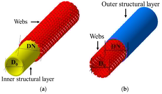
Figure 1.
The overview of the proposed GFRP pipe: (a) Outer stiffened pipe; (b) inner stiffened pipe.
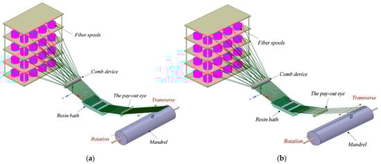
Figure 2.
Schematic of manufacturing process: (a) Continuous arrangement winding; (b) spacing arrangement winding.

Table 1.
Mechanical properties of E-Glass Fiber and unsaturated polyester resin.
2.2. Fabrication of Test Specimens
To investigate the effect of the proposed GFRP pipes on the PS, comparison tests were conducted with the plain GFRP pipes and two groups of GRFP pipe specimens were tested, each including proposed and plain pipes. One group had diameters of 400 mm, and the other group had diameters of 500 mm. The proposed GFRP pipe and the plain pipe in the same group used almost equal weight of materials to ensure cost consistency. The pipes had different nominal diameters and different winding methods, i.e., DN = 400 mm (continuous arrangement winding), DN = 400 mm (spacing arrangement winding), DN = 500 mm (continuous arrangement winding), and DN = 500 mm (spacing arrangement winding), where DN refers to nominal diameter. The fabrication details of each part of the tested pipe specimens are listed in Table 2 and the corresponding geometric properties are presented in Table 3.
Table 2.
Fabrication details of each part of the tested pipe specimens.
Table 3.
GFRP pipe geometric properties.
Two types of spiral winding were used in this research, as illustrated in Figure 2. The manufacturing process and test specimens of the proposed GFRP pipe are shown in Figure 2, Figure 3 and Figure 4. The manufacturing details were as follows:
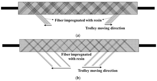
Figure 3.
The schematic of moving direction for impregnated fiber: (a) Continuous arrangement; (b) spacing arrangement.
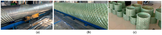
Figure 4.
Manufacturing process of the proposed GFRP pipe specimens: (a) Wrapping impregnated GRFP; (b) GRFP pipe after wrapping; (c) GRFP pipe test specimen.
(a) For outer stiffened GRFP pipes:
(1) On the pipe mandrel of the continuous winding system, the glass fiber continuous yarn was dipped in resin, and then wound through the mandrel device to form the inner structural layer using the continuous arrangement winding method as presented in Figure 2a. The thickness of the inner structural layer can be designed according to the pressure grade of the pipeline, and the thickness range is 1–50 mm;
(2) On the inner structure layer, the web core was formed by cross winding of glass fiber continuous yarn with a discontinuous arrangement, as presented in Figure 2b. The warp orientation relative to the pipe axial axis was θ = ±55° (Figure 2a). The web tightening layer can be one layer or multi-layer, with a thickness range of 1–50 mm;
(3) The specimens were consolidated for 48 h by curing at a constant temperature of 25 °C, after which the pipes were easily demolded (Figure 4b).
(b) For inner stiffened GRFP pipes:
(1) The mandrels were first used to manufacture the stiffened GRFP pipes, where the impregnated E-glass was rotated around the mandrel by cross winding using the spacing arrangement winding method, as presented in Figure 2b, until the targeted number of layers was achieved. The winding orientation relative to the pipe axial axis was θ = ±55° (Figure 2b).
(2) On the web-reinforced layer, the continuous glass fiber yarn was wound by continuous arrangement winding equipment (as shown in Figure 2a) to form an outer structural layer, where the winding orientation relative to the pipe axial axis was θ = ±55°. The thickness of the outer structural layer can be designed according to the pressure grade and pipe stiffness of the pipeline, and the thickness range is 1–20 mm;
(3) The specimens were consolidated for 48 h by curing at a constant temperature of 25 °C, after which the pipes were easily demolded (Figure 4b).
(c) For plain GRFP pipes:
As shown in Figure 2a, the glass fiber continuous yarn was dipped in resin, and then wound through the mandrel device by continuous winding to form the whole structural layer, where the thickness range is 1–50 mm.
During the winding process, the mandrels were rotated continuously, while the impregnated fiber moved along the axis of the mandrels, as presented in Figure 3. Overall, the proposed method involves a combination of the continuous arrangement filament winding shown in Figure 2a and the spacing arrangement winding in Figure 2b, with the latter forming the stiffened part and the former used for the structural part. The entire structure of the plain pipe was constructed by using the former technique only.
The test specimens of 300 mm in Figure 4c were cut from the full length of each type of GFRP pipe (as illustrated in Figure 4b). Twelve pipe specimens were selected, with three coupon specimens selected for each specific configuration of winding method and internal diameter. According to GB/T 2577-2005 [39], the mass fractions of resin in the composite pipe for the samples extracted from each group of coupon samples were determined using the loss-on-ignition (LOI) test, as shown in Figure 5. The obtained mass fractions of resin are listed in Table 3.
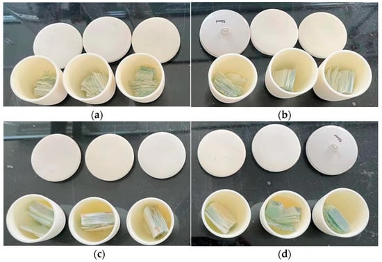
Figure 5.
Samples for the loss-on-ignition (LOI) test: (a) Plain samples of DN 400; (b) Plain samples of DN 500; (c) Stiffened samples of DN 400; (d) Stiffened samples of DN 500.
3. Stiffness Investigation of the GFRP Pipe
3.1. Flatwise Compression Tests of the Proposed GFRP
Stiffness is one of the most important properties of buried GFRP pipe structures, and represents the deformation resistance and stability of the pipe [9]. The following section presents the investigations into the ring stiffness of the newly proposed pipe structure under a flatwise compressive loading condition. Because the calculation method of determining ring stiffness is not sufficiently accurate, the ISO standard stipulates that ring stiffness should be calculated by results after testing [40]. According to the ISO7685-2019 test method, the specified pipe samples were vertically compressed between two parallel plates according to the specified conditions. The initial ring stiffness can be calculated using the following formula:
where F is the applied load, expressed in newtons; y is the deflection, expressed in meters; L is the length of the specimen; and f is the deflection coefficient, given by the formula:
in which Dm is the mean diameter, expressed in meters.
s0 = f × F/(L × y),
f = 1860 + (2500 × y/Dm),
To validate the applied theory and gain an in-depth insight into the failure mechanisms of the newly developed pipe structure, flatwise compression tests were carried out. The pipe specimens were cut from the prepared pipes. As shown in Figure 6, a universal testing machine (CMTS: SHK-A309) was employed to perform the flatwise compression tests following the standard ISO7685-2019 [40]. The pipe specimens were placed between two loading plates and a concentrated force was applied on the top loading plate to uniformly distribute the load over the circular cross-section of the specimen (as shown in Figure 6). In each of the GRFP pipe specimens, four strain gauge rosettes were attached in the middle cross-section of the specimen with angles of 0°, 45°, 90° and 180° to the vertical diameter direction, respectively, as illustrated in Figure 7. Each rosette consisted of three unidirectional strain gauges of axial, oblique and hoop, respectively, where the axial direction was aligned in the longitudinal direction of the pipe.
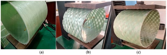
Figure 6.
Flatwise compression tests of GRFP pipe specimens: (a) Plain type; (b) outer stiffened type; (c) inner stiffened type.
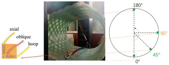
Figure 7.
Locations of the strain gauge rosettes.
Before applying displacement loads, 100 N was applied to the test specimens. Then, the corresponding deflections and loads were tared. Next, specimens were continuously loaded with a speed of 5 mm/min until final failure.
3.2. Theoretical Analysis of Initial Ring Stiffness of the GFRP Pipes
According to ISO7865-2019, the stiffness (S) of a plain GFRP pipe (simplified as: N) can be defined as a measure of resistance to ring deflection under external load, which can be calculated as follows:
where E is the apparent modulus of elasticity as determined in the ring stiffness test, in newtons per square meter; Dm is the mean diameter of the pipe, in meters; I is the second moment of area in the longitudinal direction per meter length, expressed in meters to the fourth power per meter, i.e.,
where e is the wall thickness of the test pipe, in meters.
S= EI/Dm3,
I = e3/12,
According to the above equations, the theoretical stiffness for the plain type of pipes can be calculated as listed in Table 4.
Table 4.
Theoretical initial ring stiffness for the plain GFRP pipes.
4. Results and Discussion
4.1. Stiffness Analysis
In this paper, 3% displacement of the inner diameter was selected for calculating the initial stiffness of the pipe specimens. Considering the large dimensions of the pipe structures, three specimens for each type of pipe were used for the compression tests to demonstrate the repeatability of their mechanical behavior. The load–displacement (L-D) curves of DN400 mm and DN500 mm are presented in Figure 8 and Figure 9, respectively.
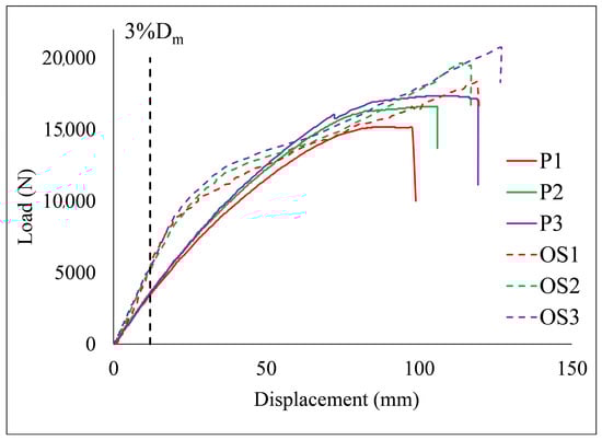
Figure 8.
Load-displacement response of DN400 pipes obtained by the plain type (P1, P2, and P3) and the outer stiffened type (OS1, OS2, and OS3), respectively.
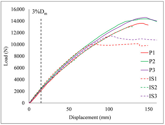
Figure 9.
Load-displacement response of DN500 pipes obtained by the plain type (P1, P2, and P3) and the outer stiffened type (OS1, OS2, and OS3), respectively.
As depicted in Figure 8, when the loading displacement reached 3% of the inner diameter (12 mm), the loads applied to the outer stiffened pipes were greater than those on the plain pipes. This phenomenon was continuously present before the loading displacement reached 30 mm, indicating that the stiffened pipes had better resistance to flatwise compressive loads. As shown in Figure 9, when the loading displacement reached 3% of the inner diameter (15 mm), there was no significant difference between the load applied to the outer stiffened pipes and the plain pipes. This phenomenon was apparent until the loading displacement reached 75 mm, suggesting that there was no enhancement on pipe stiffness brought about by the inner stiffened pipes. To evaluate quantitively the effects of stiffened structures on resistance to flatwise compressive loads, the ring stiffnesses (s0) of the tested DN400 and DN500 pipe specimens were calculated by Equation (1), listed respectively in Table 5.
Table 5.
Comparison of pipe ring stiffness results under different structural designs at 3% Dm displacement point.
According to the standard, the tested stiffness for pipes should be no smaller than the theoretical stiffness for the plain type of pipes, i.e., 16,176.48 Pa for DN400 pipes and 10,035.57 Pa for DN500 pipes. As shown in Table 5, the tested stiffness of each specimen was greater than the theoretical, meaning that all the specimens met the stiffness requirements. Comparing the stiffnesses of the plain pipes with those of the outer stiffened ones, we can see that the latter increased by an average of 38.7%. As presented in Table 5, the average ring stiffness of each tested specimen was slightly greater than the theoretical, meaning that all the specimens met the stiffness requirements. Comparing the stiffnesses of the plain pipes with those of the inner stiffened ones, it was observed that the latter were larger than the former by an average of 16.7%, and the latter increased (16.7%) much smaller than the former (38.7%) did. As shown in Table 3, with the same weight of fiber used, the average thicknesses for DN400 specimens of the stiffened and non-stiffened pipes were 11.25 mm and 8.42 mm, respectively, with a difference between the wall thicknesses of 2.83 mm. Those for DN500 specimens were 9.83 mm and 8.97 mm, respectively, with a thickness difference of 0.86 mm. According to Equations (2) and (3), the ring stiffness is proportional to the third power of wall thickness, therefore, the difference between ring stiffness of stiffened and non-stiffened pipes was greater for the D400 specimens than for the D500 specimens.
4.2. Deformation Analysis
4.2.1. Plain Pipes Compared with the Outer Stiffened Pipes
The typical strain–time curves for each type of pipe with the same internal diameter of 400 mm and same materials are given in Figure 10 and Figure 11, respectively. It can be seen that the strains increased with the increased compressive load throughout the loading process, and the mechanical behaviors for both pipes exhibited a linear trend before the final structure failure. The results also show that there was a certain level of consistency between the strain responses in each pipe group. For instance, the strains measured at different points along the axis of the pipe were small, which is mainly attributed to the loading carried out along the radial direction of the pipe. The strains increased most quickly at the 0° oblique point and 90° hoop point, especially at the point of the 90° hoop in Figure 10, which resulted in the first local fractures of the outer web at that place (as shown in Figure 14). The applied compressive load acted on the specimen and deformed the cross-section from the original circular shape into an oval shape. With compressive loads applied continuously, the minor axis of the ovalized cross-section became shorter and its major axis grew longer. Then, the point at 90° was farthest from the major axis, and the inner wall was under pressure. Correspondingly, the deformation at the 45° point was relatively small, so the strain levels in the three directions at this point were low. The deformations at points of 0° and 180° were similar, and were the farthest points from the minor axis of the oval, where the inner wall was under tension, and the hoop strain increased with the increase of the load.
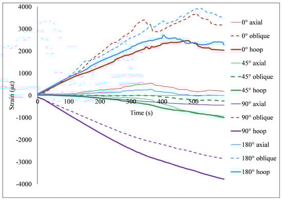
Figure 10.
A typical strain-time curve for the outer stiffened type of DN400.
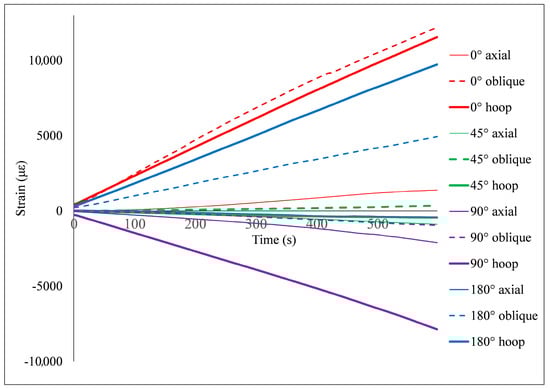
Figure 11.
A typical strain-time curve for the plain type of DN400.
4.2.2. Plain Pipes Compared with Inner Stiffened Pipes
The typical strain–time curves for each type of pipe with a diameter of 500 mm are given in Figure 12 and Figure 13, respectively. Some obvious general phenomena in Figure 12 and Figure 13 are similar to those described in Section 4.2.1. For instance, the strains increased with the increased application of compressive loading. Both sets of results showed that the strains measured at different points along the axis of the pipe were small, which is mainly attributed to the loading carried out along the radial direction of the pipe. The strains increased most quickly at the 0° hoop point and the 180° hoop, especially at the point of 180° hoop of the inner stiffened pipe (as shown in Figure 12), which resulted in the first local fractures of the inner web at that place (as shown in Figure 16). The appearance of the cross-section gradually changed from the original circular shape into an oval shape with the increase of load; in the ovalized cross-section, the minor axis became shorter and the major axis lengthened with an increase in the applied compressive loads. Then, the point at 90° was the farthest from the major axis, and the inner wall was under pressure. Correspondingly, the deformation at the 45° point was relatively small, so the strain levels in the three directions at this point were low. The deformations at points of 0° and 180° were similar, these being the farthest points from the minor axis of the oval, where the inner wall was under tension and the hoop strain increased fastest with increasing load.
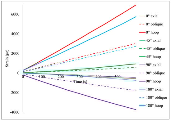
Figure 12.
A typical strain-time curve for the inner stiffened type of DN500.
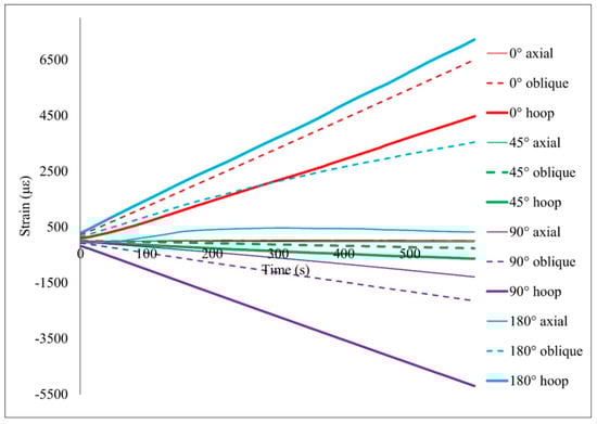
Figure 13.
A typical strain-time curve for the plain type of DN500.
Comparing the results of Figure 10 and Figure 12, the strain curve of the outer stiffened pipe fluctuated obviously in the later stage of loading, mainly due to the ductile fracture of fibers in the stiffened layer. Moreover, no shear failure occurred between the stiffened layer and the plain winding structural layer before the test was terminated, and there were obvious failure signs before the sample lost its bearing capacity. The strain curve of the inner stiffened pipe was basically a straight line. Because there was no support inside the stiffened layer, the main failure mode was ductile shear failure between the stiffened layer and the plain winding structural layer, which is in good agreement with the test results (e.g., delamination between the two layers as shown in Figure 17).
4.3. Failure Mode
4.3.1. Plain Pipes Compared with the Outer Stiffened Pipes
The damaged areas of loaded stiffened specimens with diameter 400 mm at different stages of 3%, 15%, 20%, and 30% diametric deflections are shown in Figure 14. As the test continued, the failure happened in the outer layer, characterized by fibers broken at 90° points, and the applied compressive load on the specimens reached 15% diametric deflection (as shown in Figure 14b). By increasing the applied compressive load, the outer fiber continuously fractured until the test was terminated, and the applied compressive load reached more than 30% diametric deflection (as shown in Figure 14d). As illustrated in Figure 14d, the inner structural layer was damaged and the correspondingly applied compressive force was measured as 19,621 N. Although according to ASTMD2412-2002 [41], the tests should have terminated when the applied compressive load on the specimens reached 20% diametric deflection, it was observed that the bearing load continued to increase as the increase of diameter deflection reached 30%, and large areas of inner structural layer breakage happened near 90°.
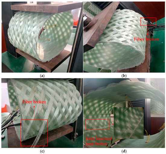
Figure 14.
Deformation of outer stiffened pipes during failure phase: (a) 3% diametric deflection; (b) 15% diametric deflection; (c) 20% diametric deflection; (d) 30% diametric deflection.
Figure 15 shows the damage areas of the plain pipe specimens during compression tests at different stages of 5%, 15%, 20%, and 30% diametric deflection. During the experiment, no visible evidence of failure was observed but there were sounds of slight fractures before 15% diametric deflection was reached, with delamination failure first occurring at the upper loading part (as shown in Figure 15b). With the increase of applied compressive load, delamination failure appeared in the bottom loading part and the areas continued to expand (as shown in Figure 15c). When the applied compressive load was almost 30% of the diametric deflection, all layers separated from each other immediately, the test was terminated with a loud bang from the tested specimen, and it was observed that the strain gauges at points of 45° and 90° had fallen off (as shown in Figure 15d).
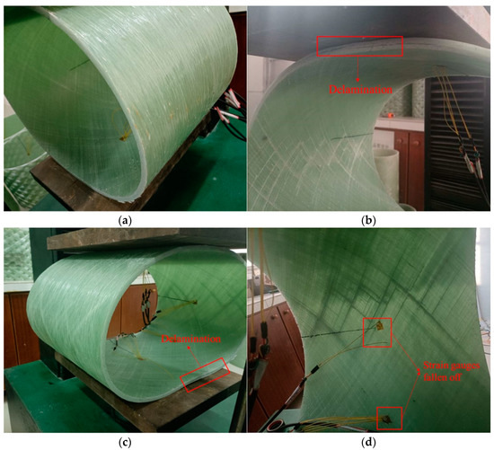
Figure 15.
Deformation of plain pipes during failure phase: (a) 3% diametric deflection; (b) 15% diametric deflection; (c) 20% diametric deflection; (d) 30% diametric deflection.
As the outer stiffened layer was supported by the inner structural layer, and was full of empty spaces due to the spacing arrangement windings, the outer fibers receiving the greatest force were ductile fractured when subjected to the compressive load. The crush failure of the stiffened pipe happened in the outer web, different from the delamination failure observed for the plain pipe, indicating a full use of the maximum load capacity of the proposed pipe. Furthermore, one should note that the cost of the two types of pipes was almost the same (the pipes of different types used the same weight of fiber and resin), while the stiffnesses of the stiffened pipes increased by an average of 38.7%, indicating great potential for cost reduction while achieving the same pipe stiffness.
4.3.2. Plain Pipes Compared with the Inner Stiffened Pipes
The damage areas of loaded stiffened specimens with diameter 500 mm at different stages of 3%, 15%, 20%, and 24% diametric deflections are shown in Figure 16. As the test continued, the failure happened at the bottom loading part, featuring delamination between the outer structural layer and the inner stiffened core, and the applied compressive load on the specimens reached almost 15% diametric deflection (as shown in Figure 16b). By increasing the applied compressive load, the delamination continuously expanded at both the bottom and upper loading parts until the test was terminated; the applied compressive load reached almost 24% diametric deflection (as shown in Figure 16d), and the correspondingly applied compressive force was measured as 12,984 N. Although according to ASTM D2412-02 [41], the tests should terminate when the applied compressive load on the specimens is at 20% of diametric deflection, it was observed until 24% diametric deflection, then all layers separated from each other immediately with large deformations.
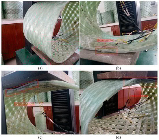
Figure 16.
Deformation of inner stiffened pipes during failure phase: (a) 3% diametric deflection; (b) 15% diametric deflection; (c) 20% diametric deflection; (d) 24% diametric deflection.
Figure 17 shows the damage area of the plain pipe specimens during compression tests at different stages of 5%, 10%, 20% and 30% diametric deflections. During the experiment, no visible evidence of failure was observed but there were sounds of slight fractures before the 15% diametric deflection reached. When the applied compressive load was 15% of the diametric deflection, deflection delamination failure occurred at the above loading part, where the interface of outer layer separated from the adjacent hoop layer (as shown in Figure 17b). Then deflection delamination continuously expanded at both the loading parts (as shown in Figure 17c,d). When the applied compressive load was almost 30% of the diametric deflection, there was a loud bang from the tested specimen and the test was terminated. As presented in Figure 17d, the deflection delamination of the plain test specimen was much less obvious than that of the stiffened one illustrated in Figure 17d.
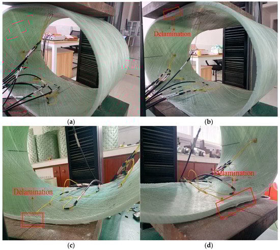
Figure 17.
Deformation of inner stiffened pipes within failure phase: (a) 3% diametric deflections; (b) 15% diametric deflections; (c) 20% diametric deflections; (d) 30% diametric deflections.
The delamination failure of the inner stiffened pipe and the plain pipe with diameter 500 mm occurred at the loading area, different from the crush failure observed for the outer stiffened pipe, indicating that the load capacity of the DN500 pipes had not been fully exploited. Although the inner stiffened pipe showed the same failure mode as the plain one, the ring stiffnesses of the former increased by an average of 16.7% when the cost of the two types of pipes was considered (pipes of different types using the same weight of fiber and resin).
In general, the damage of the stiffened pipe first occurred at the point starting in the cutting section of the pipe, as shown in Figure 14b and Figure 16b, where it easily resulted in stress concentration. Due to the different deformations between the stiffened layer and structural layer, they separated from each other at this point. With the increase of load, the separated areas expanded along the winding direction of the reinforcement, as shown in Figure 14c and Figure 16c, resulting in more damaged fibers, as shown in Figure 14d and Figure 16d. In engineering practice, the pipeline is continuous, and the connecting joints are strengthened by measures, such as butt wrapping, sleeve or socket connection. Therefore, the delamination failure of the stiffened pipes may not happen at the cut end of the stiffened pipes, which suggests that the initial stiffness for practical applications may be slightly higher. The damage of the plain pipe first occurred in the structural layer near the upper and lower loading positions, where the delamination happened among the winding layers in varying degrees, as presented in Figure 15b and Figure 17b. As the load continued to increase, the plain pipe finally buckled in varying degrees, and the deformation displayed a wave shape throughout the pipe wall, as presented in Figure 15d and Figure 17d.
Meanwhile, the interior of the stiffened pipe may provide a good solution for the concrete–GFRP interface bonding problem. As research has shown, advanced grid stiffened (AGS) FRP tube-confined concrete cylinders had stronger interfacial bonding than regular FRP tube-confined concrete cylinders [38]. This is mainly because the inner surface of AGS FRP tube is rough while that of regular FRP tubing is smooth. Similarly, compared with of smooth surface plain pipes, our proposed pipes have rough surfaces with the potential to improve the concrete–GFRP interfacial bonding force.
5. Limitation and Future Work
Testing of the newly proposed stiffened pipes has shown that the designed structure can significantly improve the ring stiffness of the specimens with suitable structural design and layering sequence, offering great potential for application in the field of sea discharge engineering with large diameters. However, the ply angle of webs, and the alternation of cross and circumferential winding webs need to be further analyzed experimentally. In addition, the design theory of this new stiffened structure needs to be further improved.
Due to the excellent corrosion resistance of FRP, many scholars are attempting to use FRP pipes as pile foundations, beams, and other structural parts in the fields of marine engineering or chemical industry. The interiors of these FRP pipes need to be filled with concrete to improve their deformation resistance. However, the smooth inner wall of plain FRP pipes easily induces interface delamination between the FRP pipe and the filled concrete, which remains a major problem. Some researchers have tried to set steel nails or spiral grooves on the inner wall of FRP pipes to improve the shear strength of the interface. That technique worked, but not very well. The newly proposed stiffened GFRP pipe presented in this paper can effectively solve this problem, providing a possibility for the application of FRP structural parts in the field of corrosion resistance.
6. Conclusions
The design methods of the pipe configuration are proposed to enhance the stiffness of GFRP pipe, based on its inherent merits, to obtain the material properties satisfying required performance. In this research, the pipe stiffness, deformation mechanism, and failure modes of pipes of different types were considered. Conclusions drawn are listed as follows:
(1) Under almost the same fabrication and material cost conditions, the flatwise compression tests showed that, with the same diameter, the ring stiffness of the outer stiffened pipe was about 38.7% greater than that of the plain one; while the ring stiffness of the inner stiffened pipe was about 16.7% greater than that of the plain one. Therefore, the proposed stiffened pipe can effectively improve the ring stiffness.
(2) As shown in Table 3, the average mass fractions of resin were calculated as 26.48%, 26.22%, 26.51%, and 27.95% for plain pipes of DN400, outer stiffened pipes of DN400, plain pipes of DN500, and inner stiffened pipes of DN500, respectively. The similar mass fractions of resin consumed by different types of pipe specimens indicate that the flowing resin in the stiffened pipes does not flow into empty spaces to cause additional usage of resin. Thus, if the same ring stiffness is considered, the proposed stiffened pipe allows low costs in batch production, which can be easily applied to engineering practice.
(3) During the flatwise compressive tests, the tests for the outer stiffened pipes and the plain pipes were terminated when the applied displacement reached almost 30% diametric deflection, while those for the inner stiffened ones were at 24% diameter deflection. In general, damage to the pipe specimens first occurred at the point (e.g., the 0°and 180° hoop directions) where the strain increased most quickly. The failure mode of the outer stiffened pipes was “ductile fracture” with obvious precursors, which is different from the brittle failure of plain pipes and inner stiffened pipes.
(4) The proposed stiffened pipe can effectively enhance the cross-section shear strength of the interface between the FRP pipe and the concrete filler. This can provide effective solutions for applications in engineering components, such as anti-corrosion columns and beams, rock-socketed pile casing in offshore engineering, etc.
Author Contributions
Conceptualization, L.K. and Q.S.; methodology, Q.S.; experiment and data analysis, B.Z.; writing—original draft preparation, L.K.; writing—review and editing, B.Z.; funding acquisition, B.Z. All authors have read and agreed to the published version of the manuscript.
Funding
This work was financially supported by the National Natural Science Foundation of China (No. 11602204).
Data Availability Statement
All data, models, or code generated or used during the study are available from the corresponding author by request.
Acknowledgments
We acknowledge the support of Nan Yang for her help with experiments and data analysis.
Conflicts of Interest
The authors declare no conflict of interest.
References
- Lu, J.; Qi, Y.; Li, Y.; Wang, X. Axial compressive performance of a composite concrete-filled GFRP tube square column. Appl. Sci. 2021, 11, 6757. [Google Scholar] [CrossRef]
- Han, Z.; Jeong, S.; Jang, J.W.; Woo, J.H.; Oh, D. Ultrasonic attenuation characteristics of glass-fiber-reinforced polymer hull structure. Appl. Sci. 2021, 11, 6614. [Google Scholar] [CrossRef]
- Pugalenthi, K.; Trung Duong, P.L.; Doh, J.; Hussain, S.; Jhon, M.H.; Raghavan, N. Online prognosis of bimodal crack evolution for fatigue life prediction of composite laminates using particle filters. Appl. Sci. 2021, 11, 6046. [Google Scholar] [CrossRef]
- Yahng, J.S.; Yee, D.S. High-speed time- and frequency-domain terahertz tomography of glass-fiber-reinforced polymer laminates with internal defects. Appl. Sci. 2021, 11, 4933. [Google Scholar] [CrossRef]
- Park, J.S.; Hong, W.H.; Lee, W.; Park, J.H.; Yoon, S.J. Pipe stiffness prediction of buried GFRP flexible pipe. Polym. Polym. Compos. 2014, 22, 17–24. [Google Scholar] [CrossRef]
- Rodríguez, E.S.; Alvarez, V.A.; Montemartini, P.E. Failure analysis of a GFRP pipe for oil transport. Eng. Fail. Anal. 2013, 28, 16–24. [Google Scholar] [CrossRef]
- Rafiee, R. Experimental and theoretical investigations on the failure of filament wound GRP pipes. Compos. Part B Eng. 2013, 45, 257–267. [Google Scholar] [CrossRef]
- Manoj Prabhakar, M.; Rajini, N.; Ayrilmis, N.; Mayandi, K.; Siengchin, S.; Senthilkumar, K.; Karthikeyan, S.; Ismail, S.O. An overview of burst, buckling, durability and corrosion analysis of lightweight FRP composite pipes and their applicability. Compos. Struct. 2019, 230, 111419. [Google Scholar] [CrossRef]
- Zhu, Y.; Chen, Z.; Jiang, Y.; Zhao, T.; Li, Y.; Chen, J.; Fang, D. Design, fabrication and stiffness analysis of a novel gfrp sandwiched pipe with stiffened core. Thin-Walled Struct. 2020, 156, 106982. [Google Scholar] [CrossRef]
- Sharma, J.R.; Najafi, M.; Marshall, D.; Kaushal, V.; Hatami, M. Development of a model for estimation of buried large-diameter thin-walled steel pipe deflection due to external loads. J. Pipeline Syst. Eng. 2019, 10, 04019019. [Google Scholar] [CrossRef]
- Rafiee, R. On the mechanical performance of glass-fibre-reinforced thermosetting-resin pipes: A review. Compos. Struct. 2016, 143, 151–164. [Google Scholar] [CrossRef]
- Rafiee, R.; Habibagahi, M.R. Evaluating mechanical performance of GFRP pipes subjected to transverse loading. Thin-Walled Struct. 2018, 131, 347–359. [Google Scholar] [CrossRef]
- Del Vecchio, F.J.C.; Reis, J.M.L.; da Costa Mattos, H.S. Elasto-viscoplastic behaviour of polyester polymer mortars under monotonic and cyclic compression. Polym. Test. 2014, 35, 62–72. [Google Scholar] [CrossRef]
- Card, R.J. Structural design of buried pipes. In Proceedings of the American Society of Civil Engineers Pipelines Conference 2012, Miami Beach, FL, USA, 19–22 August 2012. [Google Scholar]
- Rafiee, R.; Mazhari, B. Evaluating long-term performance of glass fiber reinforced plastic pipes subjected to internal pressure. Constr. Build. Mater. 2016, 122, 694–701. [Google Scholar] [CrossRef]
- Rafiee, R.; Reshadi, F. Simulation of functional failure in grp mortar pipes. Compos. Struct. 2014, 113, 155–163. [Google Scholar] [CrossRef]
- Diniz Melo, J.D.; Levy Neto, F.; de Araujo Barros, G.; de Almeida Mesquita, F.N. Mechanical behavior of grp pressure pipes with addition of quartz sand filler. J. Compos. Mater. 2011, 45, 717–726. [Google Scholar] [CrossRef]
- Xia, M.; Takayanagi, H.; Kemmochi, K. Bending behavior of filament-wound fiber-reinforced sandwich pipes. Compos. Struct. 2002, 56, 201–210. [Google Scholar] [CrossRef]
- Wang, P.; Lei, Y.; Yue, Z. Experimental and numerical evaluation of the flexural properties of stitched foam core sandwich structure. Compos. Struct. 2013, 100, 243–248. [Google Scholar] [CrossRef]
- Tilbrook, M.T.; Deshpande, V.S.; Fleck, N.A. The impulsive response of sandwich beams: Analytical and numerical investigation of regimes of behaviour. J. Mech. Phys. Solids 2006, 54, 2242–2280. [Google Scholar] [CrossRef]
- Waqas, H.M.; Shi, D.; Tong, L.; Imran, M.; Khan, S.Z.; Ahmed, W.; Qureshi, S.R. Conceptual design of composite bridge sandwich structure. Appl. Sci. 2021, 11, 214. [Google Scholar] [CrossRef]
- Jin, F.; Chen, H.; Zhao, L.; Fan, H.; Cai, C.; Kuang, N. Failure mechanisms of sandwich composites with orthotropic integrated woven corrugated cores: Experiments. Compos. Struct. 2013, 98, 53–58. [Google Scholar] [CrossRef]
- Fan, H.; Zhou, Q.; Yang, W.; Jingjing, Z. An experiment study on the failure mechanisms of woven textile sandwich panels under quasi-static loading. Compos. Part B Eng. 2010, 41, 686–692. [Google Scholar] [CrossRef]
- Fan, H.; Yang, W.; Zhou, Q. Experimental research of compressive responses of multi-layered woven textile sandwich panels under quasi-static loading. Compos. Part B Eng. 2011, 42, 1151–1156. [Google Scholar] [CrossRef]
- Zheng, J.; Zhao, L.; Fan, H. Energy absorption mechanisms of hierarchical woven lattice composites. Compos. Part B Eng. 2012, 43, 1516–1522. [Google Scholar] [CrossRef]
- Xia, M.; Takayanagi, H.; Kemmochi, K. Analysis of multi-layered filament-wound composite pipes under internal pressure. Compos. Struct. 2001, 53, 483–491. [Google Scholar] [CrossRef]
- Mertiny, P.; Ellyin, F.; Hothan, A. An experimental investigation on the effect of multi-angle filament winding on the strength of tubular composite structures. Compos. Sci. Technol. 2004, 64, 1–9. [Google Scholar] [CrossRef]
- Sun, F.; Fan, H.; Zhou, C.; Fang, D. Equivalent analysis and failure prediction of quasi-isotropic composite sandwich cylinder with lattice core under uniaxial compression. Compos. Struct. 2013, 101, 180–190. [Google Scholar] [CrossRef]
- Caratelli, A.; Meda, A.; Rinaldi, Z.; Spagnuolo, S.; Maddaluno, G. Optimization of GFRP reinforcement in precast segments for metro tunnel lining. Compos. Struct. 2017, 181, 336–346. [Google Scholar] [CrossRef]
- Niknejad, A.; Assaee, H.; Elahi, S.A.; Golriz, A. Flattening process of empty and polyurethane foam-filled E-glass/vinylester composite tubes—An experimental study. Compos. Struct. 2013, 100, 479–492. [Google Scholar] [CrossRef]
- Rouzegar, J.; Assaee, H.; Niknejad, A.; Elahi, S.A. Geometrical discontinuities effects on lateral crushing and energy absorption of tubular structures. Mater. Des. 2015, 65, 343–359. [Google Scholar] [CrossRef]
- Moeinifard, M.; Liaghat, G.; Rahimi, G.; Talezadehlari, A.; Hadavinia, H. Experimental investigation on the energy absorption and contact force of unstiffened and grid-stiffened composite cylindrical shells under lateral compression. Compos. Struct. 2016, 152, 626–636. [Google Scholar] [CrossRef]
- Sun, G.; Guo, X.; Li, S.; Ruan, D.; Li, Q. Comparative study on aluminum/GFRP/CFRP tubes for oblique lateral crushing. Thin-Walled Struct. 2020, 152, 106420. [Google Scholar] [CrossRef]
- Li, S.; Guo, X.; Li, Q.; Ruan, D.; Sun, G. On lateral compression of circular aluminum, CFRP and GFRP tubes. Compos. Struct. 2020, 232, 111534. [Google Scholar] [CrossRef]
- Eyvazinejad-Firouzsalari, S.; Dizhur, D.; Jayaraman, K.; Chouw, N.; Ingham, J.M. Flax fabric-reinforced epoxy pipes subjected to lateral compression. Compos. Struct. 2020, 244, 112307. [Google Scholar] [CrossRef]
- Xia, M.; Takayanagi, H.; Kemmochi, K. Analysis of transverse loading for laminated cylindrical pipes. Compos. Struct. 2001, 53, 279–285. [Google Scholar] [CrossRef]
- Guedes, R.M. Stress analysis of transverse loading for laminated cylindrical composite pipes: An approximated 2-d elasticity solution. Compos. Sci. Technol. 2006, 66, 427–434. [Google Scholar] [CrossRef]
- Guedes, R.M. Stressstrain analysis of a cylindrical pipe subjected to a transverse load and large deflections. Compos. Struct. 2009, 88, 188–194. [Google Scholar] [CrossRef]
- Ji, G.; Ouyang, Z.; Li, G. Experimental investigation into the interfacial shear strength of ags-frp tube confined concrete pile. Eng. Struct. 2009, 31, 2309–2316. [Google Scholar] [CrossRef]
- ISO7685-2019; Glass-Reinforced Thermosetting Plastics (GRP) Pipes- Determination of Initial Ring Stiffness. ISO: Geneve, Switzerland, 2019.
- ASTMD2412-2002; Standard Test Method for Determination of External Loading Characteristics of Plastic Pipe by Parallel-Plate Loading. American Society for Testing and Materials: West Conshohocken, PA, USA, 2002.
Publisher’s Note: MDPI stays neutral with regard to jurisdictional claims in published maps and institutional affiliations. |
© 2022 by the authors. Licensee MDPI, Basel, Switzerland. This article is an open access article distributed under the terms and conditions of the Creative Commons Attribution (CC BY) license (https://creativecommons.org/licenses/by/4.0/).