Article

Horizontal Active Noise Control Based on Wave Field Reproduction Using a Single Circular Array in 3D Space

1
School of Mechanical Engineering, Gwangju Institute of Science and Technology, 123 Cheomdangwagi-ro, Buk-gu, Gwangju 61005, Gyeonggi, Korea
2
Republic of Korea Naval Academy, 1, Jungwon-ro, Jinhae-gu, Changwon-si 51698, Gyeongsangnam-do, Korea
3
Satellite devision, Hanwha systems, 491-23, Gyeonggidong-ro, Namsa-myeon, Cheoin-gu, Yongin-si 17121, Gyeonggi-do, Korea
*
Author to whom correspondence should be addressed.
Appl. Sci. 2022, 12(20), 10245; https://doi.org/10.3390/app122010245
Submission received: 26 September 2022 / Revised: 5 October 2022 / Accepted: 10 October 2022 / Published: 12 October 2022
(This article belongs to the Special Issue Active Vibration and Noise Control)

Abstract

:
In this paper, we propose horizontal active noise control (ANC) using two-dimensional wave field information alone. By reducing the control space to a horizontal plane, the number of microphones and speakers was considerably reduced compared with ANC systems using three-dimensional wave field information. The radii of the reference, microphone, and loudspeaker array were determined based on the wave field reproduction error. Accordingly, the simulation and experimental results of the proposed ANC system were presented based on the use of five microphones and loudspeakers using conventional ANC algorithms. Overall, an average noise reduction of 20 dB was observed inside the microphone array with a radius of 0.5 m for tonal noise at 200 Hz. This performance is acceptable with a drastically reduced number of microphones and speakers. The findings of this study, along with further research conducted in a reverberant room, represent a significant contribution to global ANC commercialization.

1. Introduction

Low-frequency noise, which is challenging to reduce using passive methods, can be reduced using a transducer-like loudspeaker or devices that generate vibration. Active structural acoustic control (ASAC), which reduces the sound power radiated into the air by controlling the vibration of the noise source [1,2], and active noise control (ANC), which cancels the sound pressure by generating an “anti” signal that has an opposite phase but equal amplitude to those generated by the noise source, have been researched [3]. Given that ASAC reduces noise emission from a noise source, global noise reduction is possible; however, if the noise is radiated from several unspecified sources, an effective reduction is not possible unless the noise source is specified. However, because ANC eliminates sound pressure propagating in the air at the microphone position, it can be effectively used in situations where the noise source is unspecified [4,5]. Local ANC is achieved by reducing the sound pressure at the microphone position; however, the wave field of the noise source must be suppressed to achieve global ANC. To achieve this, acoustic energy is selected as the cost function, and an additional microphone has been used to obtain the particle velocity. As a cost function, acoustic energy is more efficient than acoustic pressure for global noise reduction [6]. In an intuitive manner, if an “anti” wave noise-source field is generated, global ANC can be achieved. Wave field reproduction provides an immersive experience to all listeners within a large target area by creating a virtual wave field of the sound source using a densely placed loudspeaker configuration. Wave field reproduction can be divided into wave field synthesis, based on the Kirchhoff–Helmholtz integral, and higher order ambisonics, which uses harmonics coefficients [7]. However, to reproduce a three-dimensional (3D) wave field, a large number of microphones and loudspeakers must be placed on Gaussian, Lebedev, and Fliege sampling grids [8]. To address this limitation, 2.5-dimensional (2.5D) wave field reproduction, which uses only horizontal spherical harmonics and generates a wave field at the height of the human ear, has been primarily used [9,10]. Given that 3D spatial information on the desired waves is prepared in advance, only a single circular loudspeaker array is required for 2.5D wave field reproduction. The circular array can be used in various fields, such as multi-sound zone reproduction and personal sound zones [11,12]. Accordingly, research has been conducted on noise control over a horizontal plane combined with wave field reproduction and ANC, and a study was pursued on pulse noise removal via fixed control filtering based on wave field synthesis [13,14]. To cope with the changing spatial information of the noise source, wave domain ANC, which minimizes spherical harmonics coefficients in 3D space using an adaptive filter, has been studied [15]. In the case of wave domain ANC, it has been proven that the global active noise control performance is better than that of the conventional ANC by using the harmonics coefficient as a cost function [16]. However, to obtain 3D spatial information and generate 3D wave fields, several challenges arise in practice owing to the large number of microphones and loudspeakers needed. A wave field, consisting of N 2 spherical harmonics coefficients, is set to L = N to consider spatial aliasing. The relation between the highest order N of spherical harmonics coefficients, angular frequency w, the speed of sound c, and wave field generation radius r N 1 for expressing 3D wave field reproduction is expressed in Equations (1) and (2).
( N 1 ) = w c r N 1
N = L
To obtain spherical harmonics coefficients of microphones and reproduce a sound field with loudspeakers, Gaussian sampling grids require 2 L 2 microphones and loudspeakers, Lebedev grids require approximately 1.3 L 2 samples, and Fliege grids require L 2 samples [8]. Figure 1 shows a Gaussian sampling grid with L = 8 [10]. To overcome this problem, research was conducted to obtain 3D spatial information by placing a multi-circular microphone array on a horizontal plane or by placing a multi-circular array in a 3D space [17,18]. In addition, a 3D sound field was reproduced with a simplified system using a multi-circular loudspeaker array. Unlike wave field reproduction, which can acquire 3D spatial information in advance, wave domain ANC must obtain 3D spatial information based on the real-time wave field analysis process.
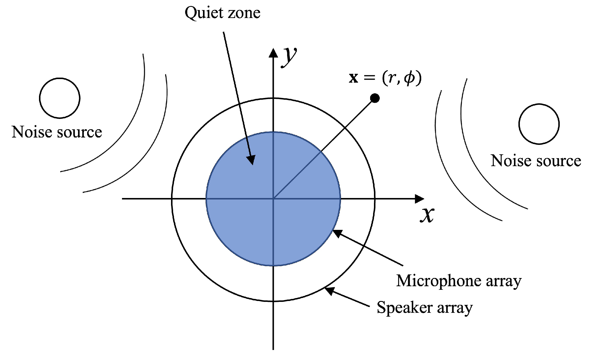
To execute this process, Sun et al. [19] used the aforementioned multi-circular array for wave domain ANC. The performance of the wave domain ANC was verified experimentally. Twelve microphones and loudspeakers were used for a noise source operated at 400 Hz to control a spherical region with a 0.25 m radius. This is a simpler system compared with the existing system, which places microphones and loudspeakers on Gaussian or Lebedev sampling grids. However, using 12 speakers and microphones to control a spherical region with a 0.25 m radius is still not suitable for global ANC commercialization. If there are sufficient sound field components parallel to the plane of interest, a horizontal wave field with a 0.25 m radius can be reproduced using only five speakers and microphones from two-dimensional (2D) wave field reproduction [20]. With this approach, if the noise control area is reduced to a horizontal plane at the height of the human ear, instead of the entire 3D space, noise reduction is possible through the ANC system with a 2D geometry, which is a simpler system compared with the multi-circular array system. Figure 1 also shows how the system can be compared with Gaussian sampling grids using only 2D spatial information when N = 8 . For ANC, omnidirectional microphones must be used, which leads to the Bessel zero problem, which in turn degrades the spatial acoustic resolution when extracting wave field information [21]. However, it is necessary to investigate to what extent the Bessel zero problem degrades the performance in the ANC region where only sound pressure reduction is of interest through wave field reproduction error. Therefore, in this study, the target area was assumed to be a horizontal plane at the height of the human ear, as shown in Figure 2, and we approached the noise reduction performance in terms of wave field reproduction using a circular array that had a remarkably reduced number of microphones and speakers while using only 2D spatial information. This approach, in terms of wave field reproduction, provides information regarding the wave field that the system can express, and it is easy to confirm the reduction in ANC performance owing to the Bessel zero problem. The ANC system was efficiently constructed according to the variables affecting the wave field reproduction error. The experimental results and simulation results were compared, and the validity of this approach was verified. The findings of this study suggests the possibility of using a single circular array for ANC systems, which adds a significant contribution to global ANC commercialization because of the simplified system.

2. 2D Wave Field Reproduction in 3D Space Using a Single Circular Array

Figure 2 shows the 2D array system and target area. An arbitrary point x consists of information related to the distance between the origin and the arbitrary point r and angle ϕ . In the free field, we assumed that it is an internal problem in which a noise source exists outside the microphone and loudspeaker array, and the noise source, microphone, and loudspeaker array exist on the x y plane. The desired wave field S D can be represented by truncated summation [10] according to Equation (3).
S D ( x , k ) m = M M S ˜ ( r , k , m ) e x p ( i m ϕ )
where k = 2 π f / c is the wavenumber, c is the wave propagation speed, f is the frequency, m is the order, M is the highest order, e x p is the exponential function, and S ˜ is the circular wave spectrum. The circular wave spectrum can be expressed by the circular harmonics coefficient and the Bessel function [22]. To avoid spatial aliasing owing to the discretization of the continuous array in Figure 2, the angular bandwidth ( M = N ) and the number of microphones and loudspeakers can be determined via Equations (1) and (4).
N u m b e r   o f   M i c r o p h o n e   a n d   l o u d s p e a k e r 2 M + 1
From Equation (4), any 2D wave field can be expressed if the 2 M + 1 circular spectrum is known. S ˜ ( r , k , m ) can be obtained using the discrete spatial Fourier transform (Equation (5)) by assuming the orthogonal property of the basis function e x p .
S ˜ m i c ( R m i c , k , m ) = 1 Q q = 1 Q S ( x q , k ) e x p ( i 2 π m ( q 1 ) / Q ) ,
where S ˜ m i c is the circular wave spectrum obtained using the microphone, R m i c is the radius from the origin to the microphone array, x q is the position of each microphone, and Q is the number of microphones. If the radial part J ( k R m i c ) is divided into both sides of Equation (5), it is called a circular harmonics coefficient and can be used as the cost function of the wave domain ANC [23]. When the Bessel function becomes zero, an error occurs in the process of extracting the circular harmonics coefficient, and this error affects the wave field reproduction error. The sound pressure of the desired wave field can be matched only within a circle with a radius of r r e f (reference circle) owing to the dimensional mismatch that occurs because the 3D wave field is expressed as a 2D array. The relationship between the circular harmonics coefficients of r r e f and those of R m i c can be expressed as [22],
S ˜ D ( r r e f , k , m ) / J m ( k r r e f ) = S ˜ m i c ( R m i c , k , m ) / J m ( k R m i c ) ,
where S ˜ D ( r r e f , k , m ) is the circular wave spectrum of the desired wave field at r r e f . Because only the 2D sound field information was used in 3D space, wave field reproduction has a lower performance than that of 2.5D wave field reproduction based on spherical harmonics coefficients. However, as aforementioned, a spherical microphone array or a multi-circular microphone array are required to obtain information on the 3D wave field [17]. A loudspeaker can be modeled as a monopole, and the wave field S s reproduced by a circular array can be expressed as
S s ( x , k ) = 0 2 π R s D ( R s , ϕ s ) G ( r R s , ϕ ϕ s ) d ϕ s ,
where R s is the radius from the point of origin to the loudspeaker array, D is the complex amplitude of each loudspeaker, and G is the free field Green’s function, which is expressed as follows:
G ( r R s , ϕ ϕ s ) = e j k x x s 4 π x x s ,
where x s is the loudspeaker position. Equation (7) can be interpreted as a circular convolution and converted as follows by the convolution theorem [24]:
S ˜ s ( r , m ) = 2 π R s D ˜ ( R s , m ) G ˜ ( r R s , m ) ,
where G ˜ ( r R s , m ) is the circular wave spectrum of the monopole, which can be expressed as
G ˜ ( r R s , m ) = n = m M j k j n ( k r ) h n ( 1 ) ( k R s ) A n m 2 P n m 2 ,
where h n ( 1 ) ( · ) is the first-kind spherical Hankel function of the n-th degree, j n ( · ) is the first-kind spherical Bessel function, and P n m is the associated Legendre function; A n m can be expressed as
A n m = 2 n + 1 2 ( n m ) ! ( n + m ) ! .
We substituted Equation (6) with Equation (9) to match the sound pressure of the desired wave field in the reference circle using the loudspeakers.
D ˜ ( R s , k , m ) = 1 2 π R s G ˜ ( r r e f R s , m ) J m ( k r r e f ) J m ( k R m i c ) S ˜ m i c ( R m i c , k , m ) .
As aforementioned, in the denominator of Equation (12), for the Bessel zero problem, J m ( k R m i c ) generates zero for every specific frequency, which affects the driving signal and the performance of wave field reproduction. The circular wave spectrum of the driving signal obtained from Equation (12) can be converted to the complex amplitude of each loudspeaker through the inverse discrete spatial Fourier transform. As shown in Equation (12), the driving signal was determined by three variables: r r e f , R m i c , and R s , which are related to the wave field reproduction error. To reproduce the wave field using the 2.5D wave field reproduction method, it is common to set r r e f to a value close to zero [24]. However, to reproduce the wave field using 2D spatial information in 3D space with minimum error, it is necessary to confirm the relation between wave field reproduction error and these three variables. Because the wave field reproduction error can be considered as the criterion of the “anti” wave field of the noise field that the circular array can produce, the ANC noise reduction performance can be predicted. Accordingly, we can organize the ANC system by setting the r r e f , R s , and R m i c values.

2.1. Wave Field Reproduction Error with Respect to r r e f

The wave field e ( x , k ) of the wave field reproduction error is expressed as follows:
e ( x , k ) = 10 log 10 S D ( x , k ) S s ( x , k ) 2 S D ( x , k ) 2 ,
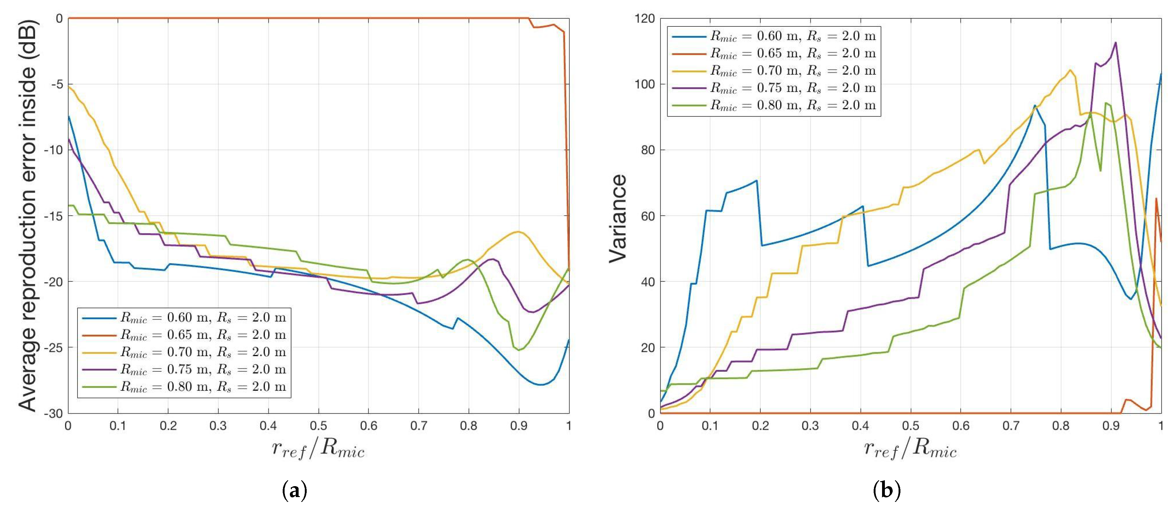
Considering the audible area, the region-of-interest (ROI) was defined as the inner part of the circle with a radius equal to R m i c − 0.1 m for calculating the average wave field reproduction error and its variance. The average reproduction error was expressed as the mean of all x of e ( x , k ) within the ROI. We assumed that the sound source existed at [5 m, 0 m], [−3 m, 3 m] and emitted a periodic signal at 200 Hz. Referring to Equations (1) and (4), 11 monopoles and microphones were placed equiangularly. Figure 3 shows the wave field reproduction results according to r r e f when R s was assumed to be 2 m, and R m i c was set to 0.65, 0.7, 0.75, and 0.8 m.
As shown in Figure 3a, the reproduction error varied according to r r e f . Interestingly, when r r e f was equal to R m i c , it yielded good performance outcomes for all R m i c radii. Unlike the 2.5D and 2D wave field reproductions in 3D and 2D spaces, respectively, wave field reproduction based on 2D spatial information in 3D space did not generate a reference circle, as shown in Figure 4c, except when r r e f = R m i c . When R m i c = 0.8 m and r r e f = R m i c , the desired wave fields, reproduced wave fields, and wave field reproduction error are shown in Figure 4a,b,d, respectively. Unlike 2.5D wave field reproduction, the wave field reproduction error inside the microphone array was not uniform, as shown in Figure 4d, because only 2D information was used to reproduce the 3D sound field. The variance for all points inside the ROI is plotted in Figure 3b to observe the wave field reproduction uniformity. Nonuniformity is undesirable in terms of a wave field reproduction that provides an immersive experience. In global ANC, where the only concern is sound pressure, the importance of nonuniformity can be reduced. Therefore, we can use a single circular array for global ANC and expect Figure 3a to indicate noise reduction when the “anti” wave field of the noise source is reproduced by the circular array with respect to r r e f .

2.2. Wave Field Reproduction Error with Radii R m i c and R s

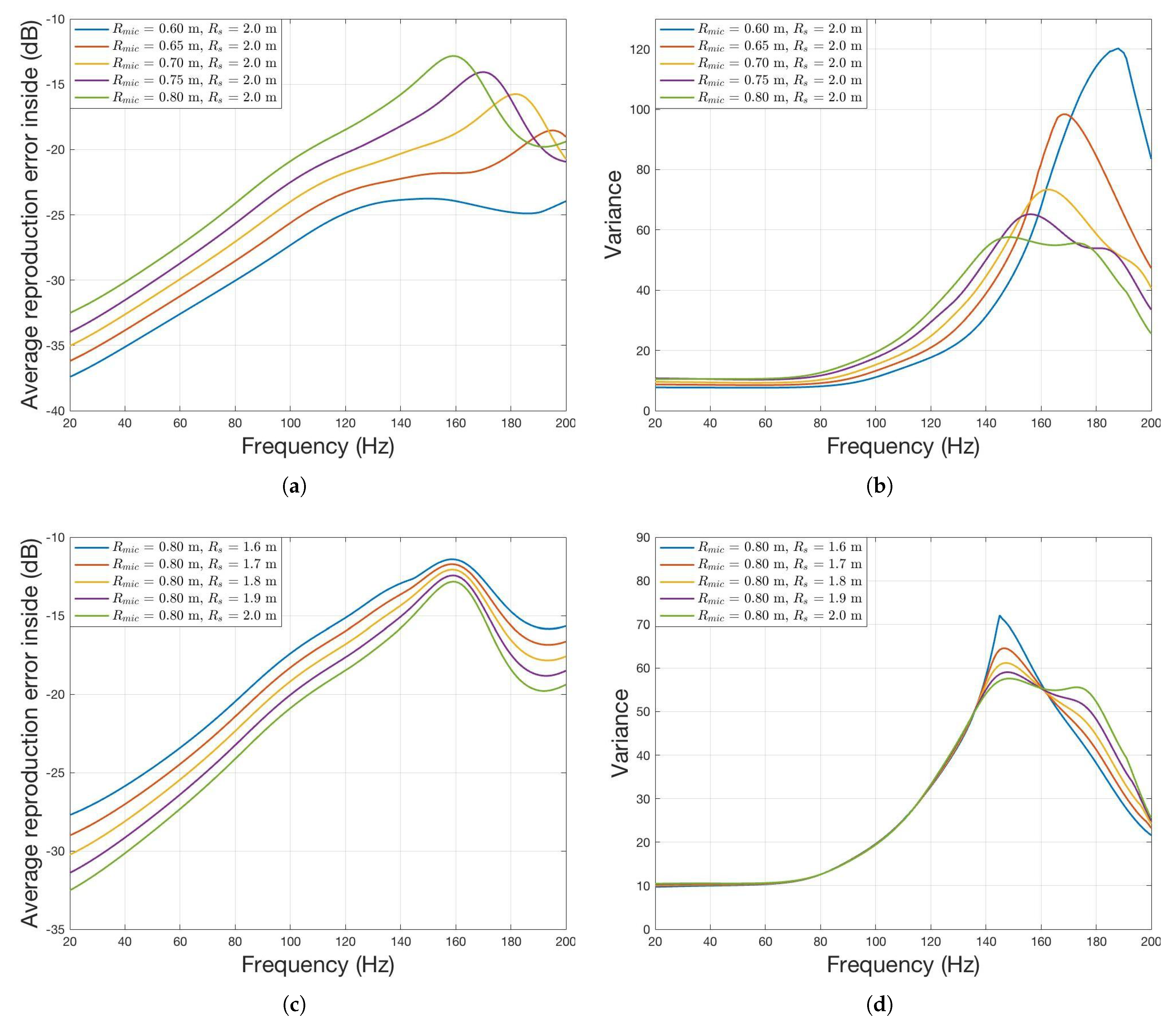
As described in the previous section, we explained how r r e f affects wave field reproduction. When r r e f = R m i c , it indicates an acceptable reproduction performance. In addition, R m i c and R s affect wave field reproduction. In the process of extracting the circular harmonics coefficients, the Bessel zero problem occurred, and the frequency of the Bessel zero problem differed according to the change of R m i c . Figure 5a,b respectively show the average reproduction error and variance according to R m i c changes when r r e f = R m i c and R s were fixed at 2 m. In contrast, Figure 5c,d show the reproduction error and variance according to R s when r r e f = R m i c and R m i c were fixed at 0.8 m.
As shown in Figure 5a, the smaller the value of R m i c (up to a frequency of approximately 160 Hz), the smaller will be the reproduction error. However, at frequencies greater than 160 Hz, an irregular pattern was observed. Similarly, as shown in Figure 5b, the smaller the R m i c value is for frequencies lower than 150 Hz, the more uniform the wave field reproduction is. As indicated, the relationship is reversed at frequencies greater than 150 Hz. As shown in Figure 5c,d, when R m i c is fixed, the reproduction error decreases as R s increases, but the variance is irregular.
The part with a large Bessel zero effect was observed as a peak in the wave field reproduction error graph. In the case of Figure 5a, as R m i c decreases, the peak was pushed back, which was attributed to the Bessel zero in the coefficient extraction process. As shown in Figure 5c, a peak occurred at the same frequency because R m i c is the same. However, even at the peak, it showed a wave field reproduction error of less than −10 dB. This means that the noise reduction performance exceeds 10 dB when ANC using a single circular array is performed, suggesting that the Bessel zero problem can be tolerated. Furthermore, these results provide information for determining the radii of the microphone and loudspeaker arrays for the dominant frequency component of the noise source when constructing an ANC system.

3. Simulation Results

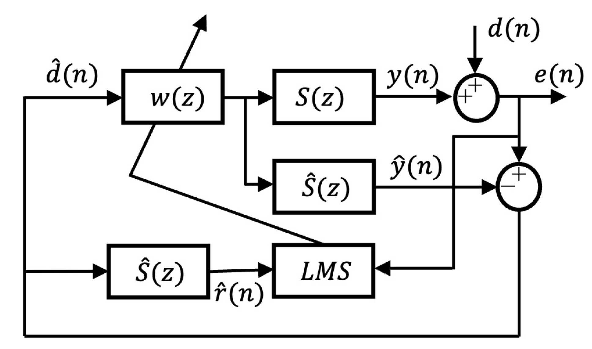
To apply the wave domain ANC that minimizes the circular harmonics coefficients of the noise source, fast Fourier transform (FFT), inverse FFT (IFFT), spatial FFT, and spatial IFFT processes are required. Control of the frequency domain causes a delay of the size of at least one FFT block [3]. To solve this problem, a spherical harmonics analysis in the time domain was performed [25,26]. However, the group delay of the finite impulse response filter is inevitable, and this group delay lowers the ANC performance. As shown in Figure 3, when r r e f = R m i c , a good wave field reproduction performance was attained with only a reference circle among other values of r r e f . Having a reference circle implies matching of the sound pressure of the desired wave field at the position of the microphone array, which suggests that, when the sound pressure is reduced at the microphone position, “anti” wave fields will be reproduced, as shown in Figure 4b. The ANC performance shown in Figure 5 can be achieved when the conventional Filtered-x least mean square (FxLMS) algorithm, which uses the sound pressure of the microphone as a cost function, is used. Considering this, experiments and simulations were conducted using the conventional ANC. The ANC simulation was performed in the same way as the existing settings. In this case, the adaptive feedback FxLMS algorithm was used to effectively manage the periodic signals originating from all directions [3] (see Figure 6); here, d ( n ) is the disturbance signal and e ( n ) is the error signal. The secondary path S ( z ) included an acoustic transfer function and digital-to-analog and analog-to-digital converters. One of the microphone array signals was used as the reference signal d ^ ( n ) . S ^ ( z ) is the estimated secondary path, and r ^ ( n ) is the estimated filtered reference signal.

3.1. Single Noise Simulations

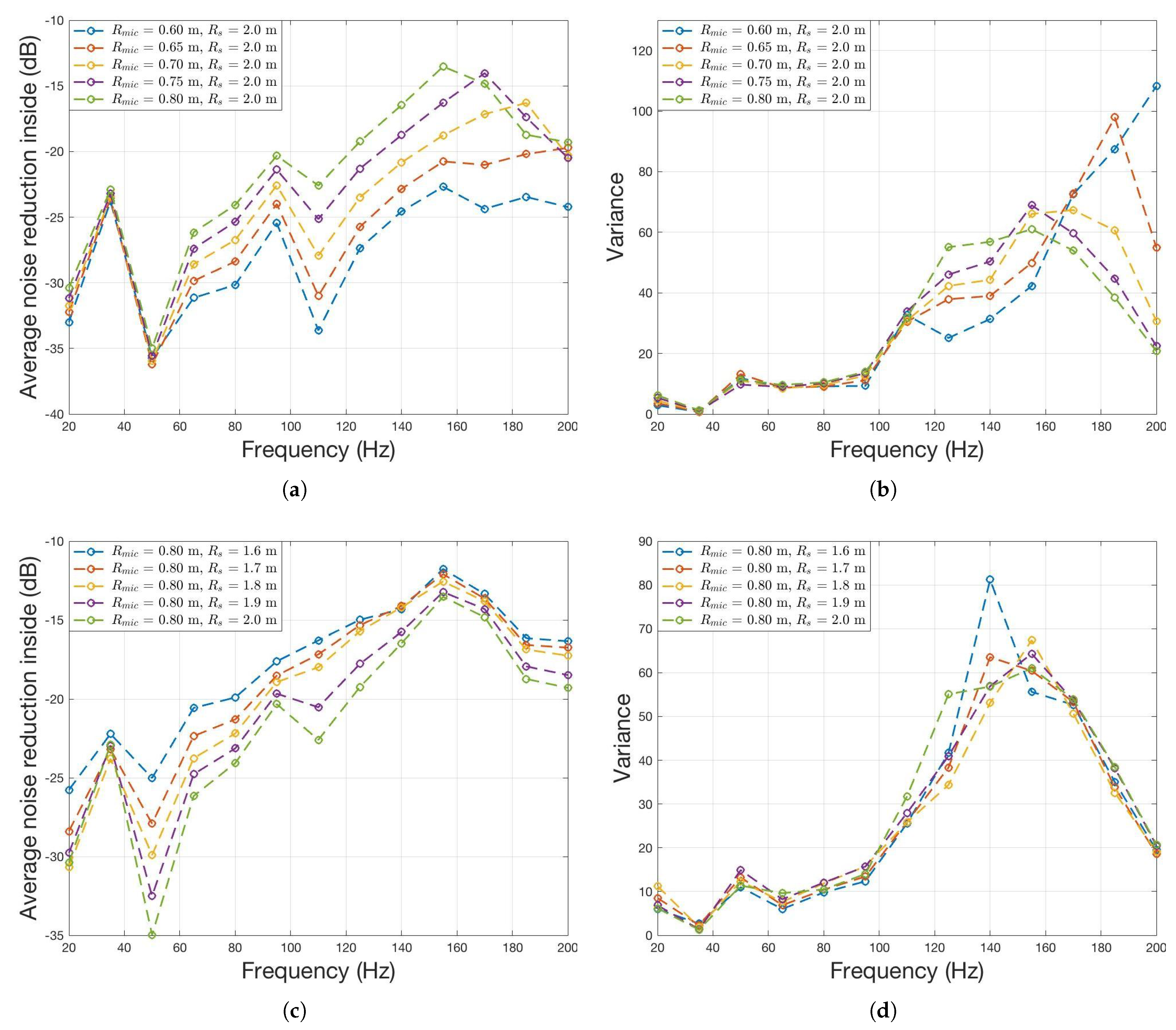
The inner part of the circle with a radius equal to R m i c – 0.1 m was assumed as the ROI, and feedback FxLMS ANC simulations were performed on the noise source, which had a single frequency component (ranging from 20 to 200 Hz in 15-Hz increments). Figure 7 shows the average noise reduction and variance within the ROI after adaptive filter convergence. The comparison of Figure 5 and Figure 7 reveals that the relative noise reduction and variance according to the change of R m i c and R s yield similar outcomes. At some specific frequency, such as 35 or 110 Hz, there was a large gap in value of the wave field reproduction error. However, because the variance was nearly the same, the noise reduction uniformity for space and wave field reproduction result were the same.

3.2. Multifrequency Noise Simulations

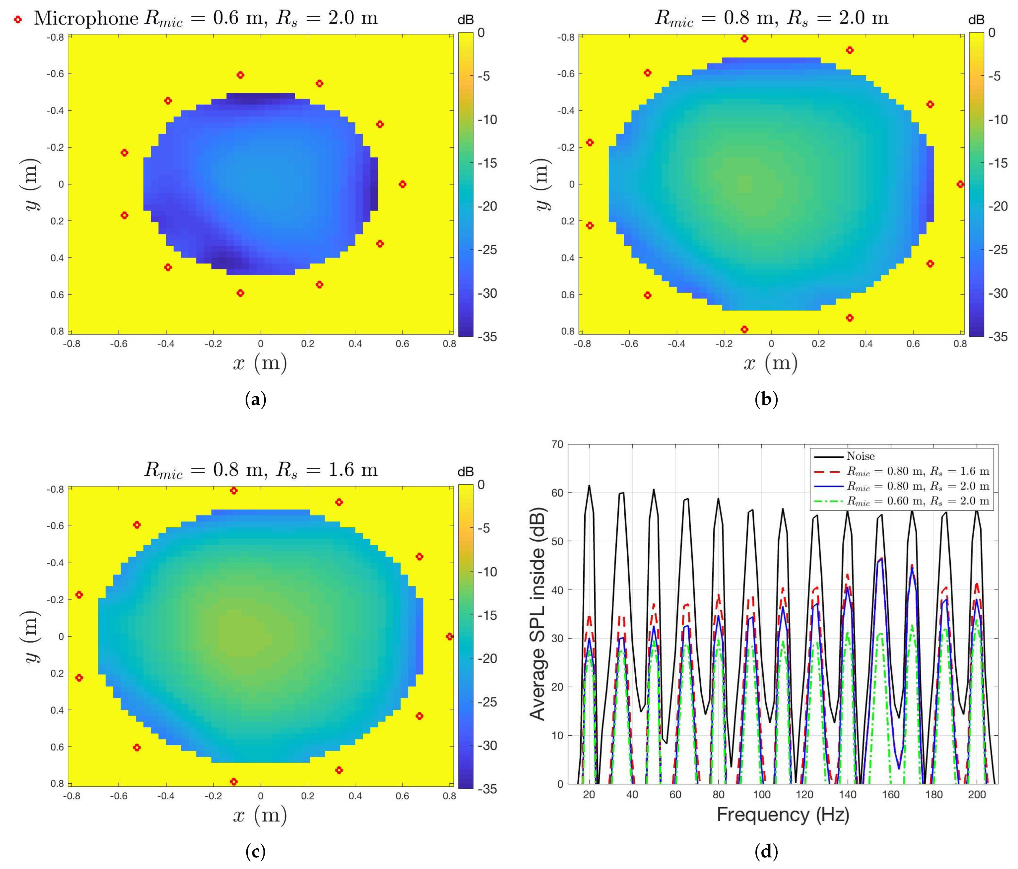
The adaptive feedback FxLMS was performed on the noise source that emits a sound in which periodic signals of the same magnitude (from 20 to 200 Hz) were added at 15-Hz intervals. The location and the number of noise sources were the same as before, and Figure 8 shows the results after adaptive filter convergence for each of the three cases: case 1 = [ R m i c = 0.6 m R s = 2.0 m], case 2 = [ R m i c = 0.8 m R s = 2.0 m], and case 3 = [ R m i c = 0.8 m, R s = 1.6 m]. The wave field after convergence is shown in Figure 8a–c, and the average sound pressure level (SPL) of the ROI in the frequency domain is shown in Figure 8d. In cases 1–3, average reductions of 27, 18, and 16.7 dB, respectively, were noted. At 155 and 170 Hz, there were no significant differences in noise reduction between cases 2 and 3. For other frequencies, the ANC performance adhered to the following order: case 1 > case 2 > case 3. This proves that the multifrequency test shows the same noise reduction trend as the single-frequency test.

3.3. Noise Reduction with Respect to the Noise Source Angle

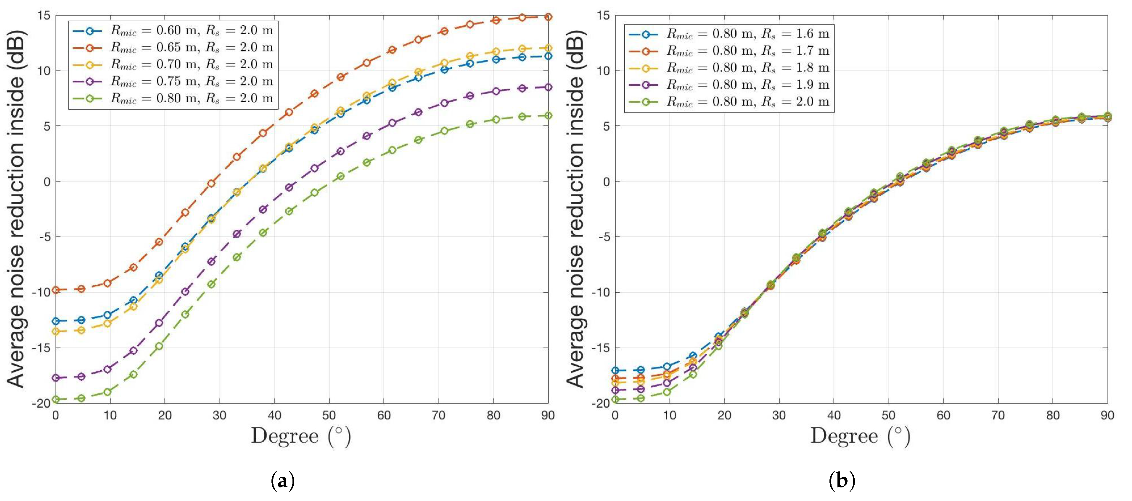
Based on the results presented thus far, the advantage of using a circular array is that the global noise reduction performance is acceptable, and the proposed ANC system configuration is simpler than the ANC system when 3D spatial information is used. However, the greatest drawback is that, when the vertical component of the noise source increases in the ROI, the circular array does not adequately reproduce the wave field of the noise source. This disadvantage will yield the same results in the ANC system. The arrangement of the microphones and loudspeakers is the same as the existing simulation, and Figure 9 shows how noise reduction is achieved depending on a noise source angle that is 5 m away from the origin. The “ 0 ” case implies that the noise source exists in the x–y plane, and the “ 90 ” case implies that it exists at [0 m, 0 m, and 5 m]. The angle at which noise is no longer reduced is different depending on the radius of the microphone array, and the radii of the loudspeaker array all yielded similar results. This information demonstrates the possibility of using a circular array for the angle of incoming noise when installed in an indoor space made of a sound-absorbing material (ceiling and floor).

4. Comparison between the Simulation and Experimental Results

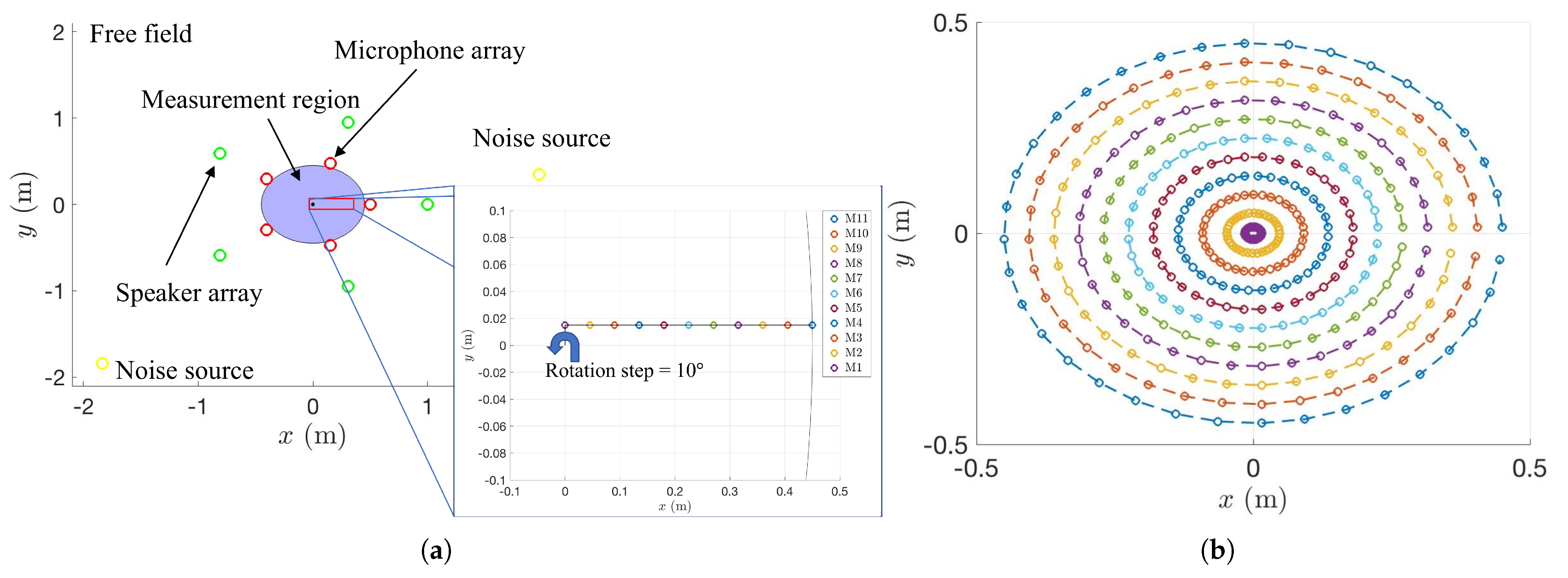
Experiments were conducted in an anechoic room with a reduced system having five error microphones and five loudspeakers according to Eqsuations (1) and (4) by using NI CRio-9039, Labview FPGA, and Realtime OS. The sound pressure was acquired through Labview FPGA using microphones and sent to Realtime OS. The FxLMS algorithm was implemented via Realtime OS through the data received. The calculated value was again passed to the FPGA to generate sound through the speaker. The experimental geometry is shown in Figure 10a.
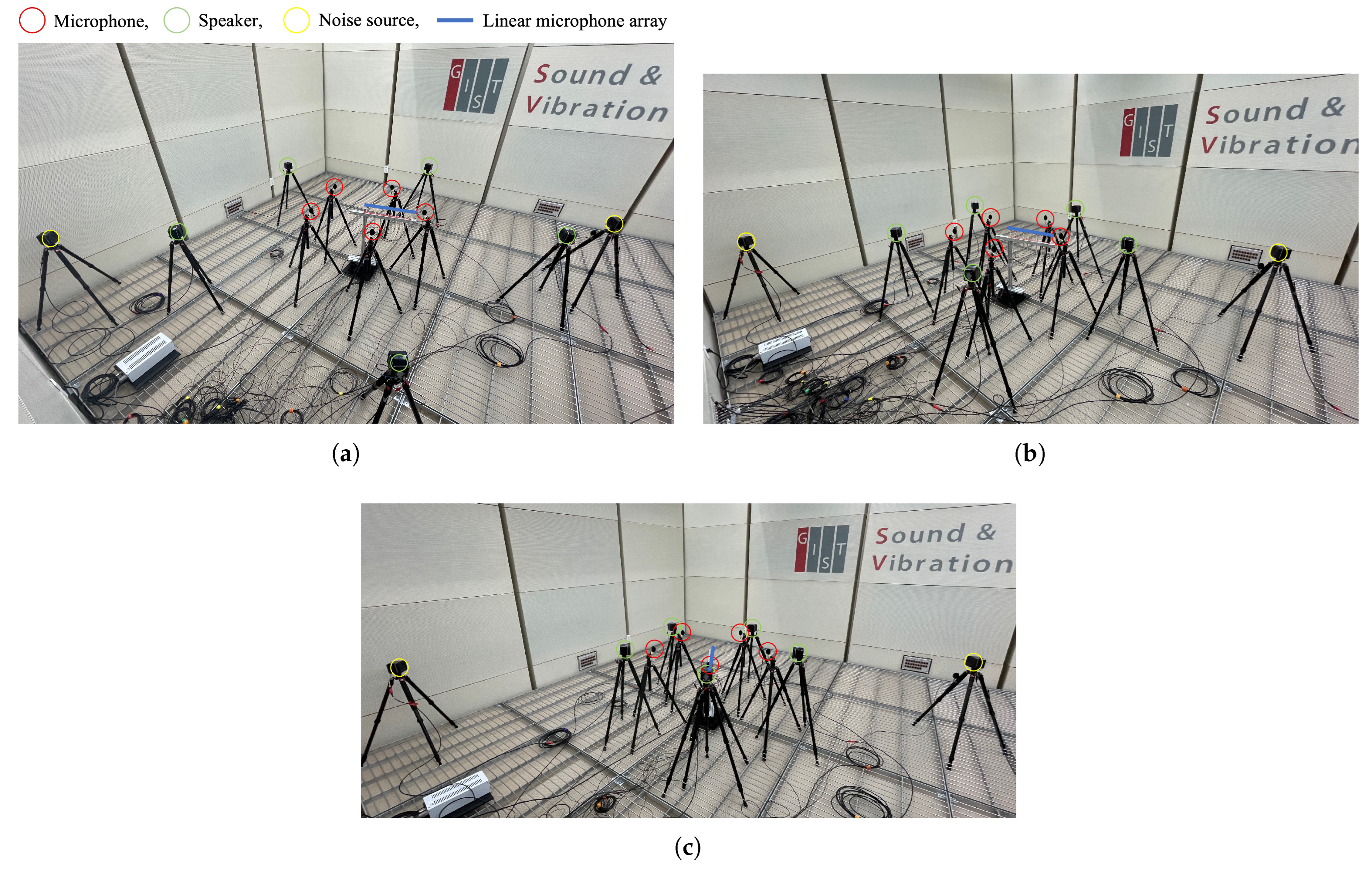
We used 11 measurement microphones (at 0.045 m intervals) to measure the quiet zone; these microphones were placed in a linear array configuration with an offset of 0.015 m in the normal direction. The inside of the quiet zone was measured at intervals of 10 through the rotational stage, and the 396 measurement points, measured by rotating each microphone in the linear array, are shown in Figure 10b. To approximate the simulation result in which the loudspeaker is modeled as a point source, an experiment was conducted using a loudspeaker with a circular membrane having a radius of 0.03 m. The noise source generated a periodic 200-Hz signal at two positions: (1.97 m, 0.35 m, and 0 m) and (−1.8735 m, −1.8735 m, and 0 m). As shown in Figure 11, case 1 = [ R m i c = 0.5 m, R s = 1.5 m], case 2 = [ R m i c = 0.5 m, R s = 1.0 m], and case 3 = [ R m i c = 0.5 m, R s = 0.7 m] were considered, and adaptive feedback FxLMS ANC was performed.
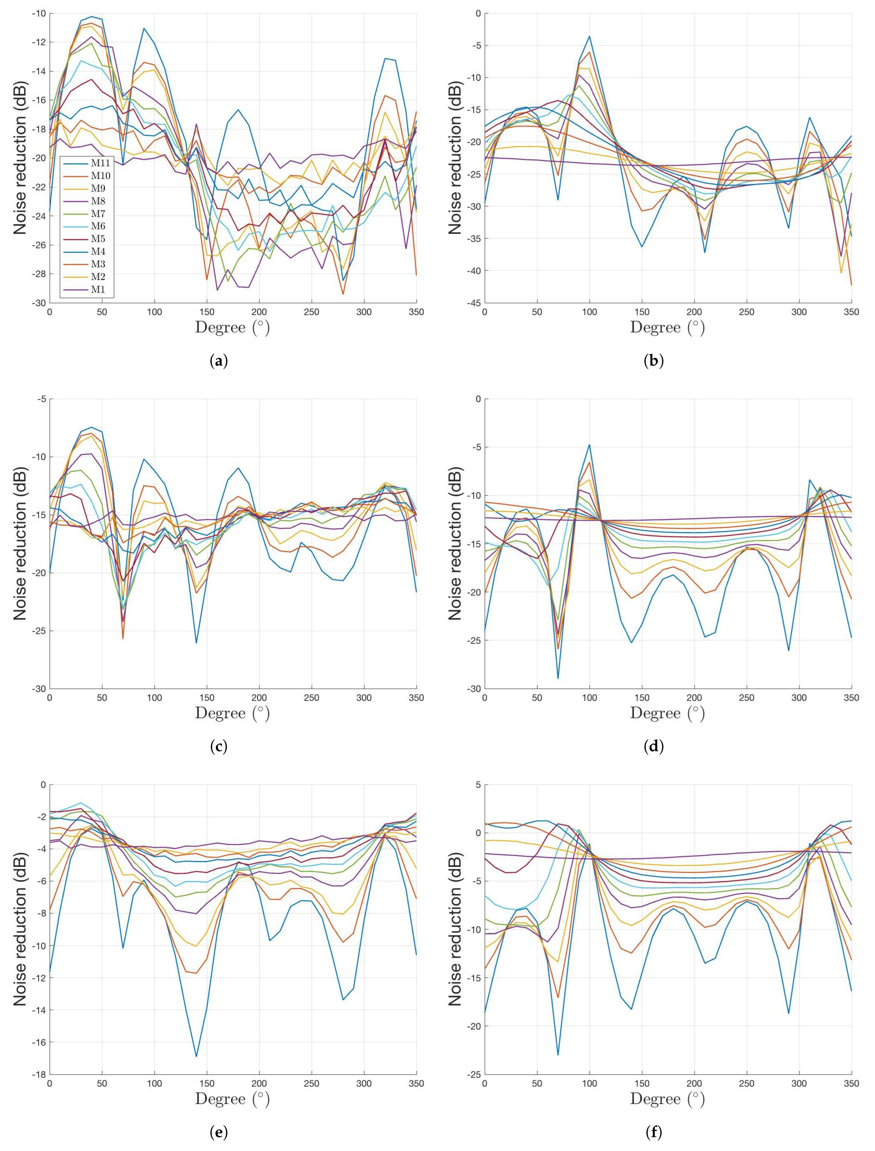
Table 1 shows the noise reduction performance outcomes for the measurement points in Figure 10b. As indicated, the performance is high in the order of case 1 > case 2 > case 3. Therefore, we proved that the radius of the loudspeaker affects the ANC performance. To compare the noise reduction between the simulation and the experiment, average noise reductions for each case are shown in Figure 12 for each rotation angle of each microphone constituting the line array. The experimental and simulation results show differences in noise reduction owing to various error factors in the experiment, such as the heights and positions of all microphones, loudspeakers, and noise speakers, or the fact that the loudspeaker is not a perfect monopole, and secondary path estimation errors. However, when the simulation and experimental results were compared, the noise reduction patterns at all set angles appeared to be similar. The amount of noise reduction with respect to the angle varied owing to the aforementioned factors, but the peak occurrence frequency and noise reduction trends according to R s were similar between the experiments and simulations. This proves that the noise reduction pattern expected from the wave field reproduction error is similar to the actual experiments. Sun et al. [19] used 12 microphones and 20 speakers to achieve a 9 dB noise reduction at the level of the dummy head within a 0.25 m hemisphere in a reverberant room using noise sources operated at 150 Hz and 200 Hz. In this study, the experiment was conducted in a free field, and five speakers and microphones were used to control the inner parts of a 0.5 m circle for a noise source operated at 200 Hz. In the case of R m i c = 0.5 m, R s = 1.5 m, maximum and minimum noise reductions of 29.4 and 10.2 dB, respectively, were obtained. If the location of the noise source is on the plane of interest, the proposed ANC system is simpler than the ANC system wherein 3D spatial information is used; however, additional research is needed on the performance degradation caused by the vertical components of the noise source in the reverberant room.

5. Conclusions

In this paper, ANC based on the use of a single circular array and 2D spatial information is proposed. In terms of wave field reproduction, the ANC performance for different radii of the microphone, loudspeaker arrays, and reference circle was investigated. In the experiment, a 20-dB average noise reduction was shown in the ROI when the radius of the microphone array was 0.5 m and that of the loudspeaker array was 1.5 m for a noise source transmitting a periodic signal at 200 Hz. In the proposed system, the number of speakers and microphones is considerably reduced compared with using the existing ANC system with 3D spatial information. In addition, using only 2D spatial information, we are one step closer to the commercialization of global ANC. Moreover, the ANC performance according to the noise source angle was also investigated, and we found that the SPL of the ROI increased when the noise source was beyond a certain angle. This disadvantage of the circular array can be reduced by installing sound-absorbing materials on the floor and ceiling of the room or using an additional microphone to achieve the vertical component of the wave field [17]. Furthermore, as the actual room has a square shape, research on ANC in terms of wave field reproduction based on the shape of various microphone arrays should be conducted in reverberant rooms [27]. The findings of this study, along with further research, demonstrate that global ANC commercialization can be achieved through a simple system.

Author Contributions

Conceptualization, S.H.; Formal analysis, S.H.; Funding acquisition, H.-g.K. and S.W.; Investigation, S.H. and J.K.; Methodology, S.H.; Project administration, H.-g.K.; Software, S.H.; Supervision, S.W.; Visualization, S.H. and J.K.; Writing—original draft, S.H. All authors have read and agreed to the published version of the manuscript.

Funding

This work was supported by a grant-in-aid HANWHA SYSTEMS.

Institutional Review Board Statement

Not applicable.

Informed Consent Statement

Not applicable.

Data Availability Statement

All data in this paper are available from the corresponding author upon reasonable request. There are no additional data.

Conflicts of Interest

The authors declare no conflict of interest.

References

  1. Elliott, S.J.; Johnson, M.E. Radiation modes and the active control of sound power. J. Acoust. Soc. Am. 1993, 94, 2194–2204. [Google Scholar] [CrossRef]
  2. Jeon, O.; Kim, H.G.; Wang, S. Optimal Filter Design of a Virtual Mechanical Impedance Control System for Multifrequency Active Sound Power Reduction of Enclosure Panels. IEEE Access 2021, 9, 104227–104241. [Google Scholar] [CrossRef]
  3. Elliott, S. Signal Processing for Active Control; Elsevier: Amsterdam, The Netherlands, 2000. [Google Scholar]
  4. Kuo, S.M.; Mitra, S.; Gan, W.S. Active noise control system for headphone applications. IEEE Trans. Control. Syst. Technol. 2006, 14, 331–335. [Google Scholar] [CrossRef]
  5. Patel, V.; Cheer, J.; Fontana, S. Design and implementation of an active noise control headphone with directional hear-through capability. IEEE Trans. Consum. Electron. 2019, 66, 32–40. [Google Scholar] [CrossRef]
  6. Parkins, J.W.; Sommerfeldt, S.D.; Tichy, J. Narrowband and broadband active control in an enclosure using the acoustic energy density. J. Acoust. Soc. Am. 2000, 108, 192–203. [Google Scholar] [CrossRef] [PubMed] [Green Version]
  7. Spors, S.; Ahrens, J. A comparison of wave field synthesis and higher-order ambisonics with respect to physical properties and spatial sampling. J. Audio Eng. Soc. 2008. Available online: http://www.aes.org/e-lib/browse.cfm?elib=14708 (accessed on 25 September 2022).
  8. Arend, J.M.; Pörschmann, C. Spatial Upsampling of Sparse Head-Related Transfer Function Sets by Directional Equalization-Influence of the Spherical Sampling Scheme; Universitätsbibliothek der RWTH Aachen: Aachen, Germany, 2019. [Google Scholar]
  9. Start, E.W. Direct Sound Enhancement by Wave Field Synthesis. Ph.D. Thesis, Delft University of Technology, Delft, The Netherlands, 1997. [Google Scholar]
  10. Ahrens, J. Analytic Methods of Sound Field Synthesis; Springer Science & Business Media: Berlin/Heidelberg, Germany, 2012. [Google Scholar]
  11. Han, Z.; Wu, M.; Zhu, Q.; Yang, J. Two-dimensional multizone sound field reproduction using a wave domain method. J. Acoust. Soc. Am. 2018, 144, EL185–EL190. [Google Scholar] [CrossRef] [PubMed] [Green Version]
  12. Poletti, M.A.; Fazi, F. An approach to generating two zones of silence with application to personal sound systems. J. Acoust. Soc. Am. 2015, 137, 598–605. [Google Scholar] [CrossRef] [PubMed] [Green Version]
  13. Kuntz, A.; Rabenstein, R. An approach to global noise control by wave field synthesis. In Proceedings of the 2004 12th European Signal Processing Conference, Vienna, Austria, 6–10 September 2004; IEEE: Piscataway, NJ, USA, 2004; pp. 1999–2002. [Google Scholar]
  14. Lapini, A.; Borchi, F.; Carfagni, M.; Argenti, F. Simulation and design of active control systems for acoustic pulse noise. Int. J. Interact. Des. Manuf. (IJIDeM) 2018, 12, 573–584. [Google Scholar] [CrossRef]
  15. Sun, H.; Abhayapala, T.D.; Samarasinghe, P.N. Active noise control over 3D space with multiple circular arrays. In Proceedings of the 2019 IEEE Workshop on Applications of Signal Processing to Audio and Acoustics (WASPAA), New Paltz, NY, USA, 20–23 October 2019; IEEE: Piscataway, NJ, USA, 2019; pp. 135–139. [Google Scholar]
  16. Zhang, J.; Abhayapala, T.D.; Zhang, W.; Samarasinghe, P.N.; Jiang, S. Active Noise Control Over Space: A Wave Domain Approach. IEEE/ACM Trans. Audio Speech Lang. Process. 2018, 26, 774–786. [Google Scholar] [CrossRef] [Green Version]
  17. Okamoto, T. Horizontal 3D sound field recording and 2.5D synthesis with omni-directional circular arrays. In Proceedings of the ICASSP 2019—2019 IEEE International Conference on Acoustics, Speech and Signal Processing (ICASSP), Brighton, UK, 12–17 May 2019; IEEE: Piscataway, NJ, USA, 2019; pp. 960–964. [Google Scholar]
  18. Abhayapala, T.D.; Gupta, A. Spherical harmonic analysis of wavefields using multiple circular sensor arrays. IEEE Trans. Audio Speech Lang. Process. 2009, 18, 1655–1666. [Google Scholar] [CrossRef]
  19. Sun, H.; Abhayapala, T.D.; Samarasinghe, P.N. A realistic multiple circular array system for active noise control over 3D space. IEEE/ACM Trans. Audio Speech Lang. Process. 2020, 28, 3041–3052. [Google Scholar] [CrossRef]
  20. Koyama, S.; Furuya, K.; Wakayama, K.; Shimauchi, S.; Saruwatari, H. Analytical approach to transforming filter design for sound field recording and reproduction using circular arrays with a spherical baffle. J. Acoust. Soc. Am. 2016, 139, 1024–1036. [Google Scholar] [CrossRef] [PubMed]
  21. Abhayapala, T.D.; Ward, D.B. Theory and design of high order sound field microphones using spherical microphone array. In Proceedings of the 2002 IEEE International Conference on Acoustics, Speech and Signal Processing, Orlando, FL, USA, 13–17 May 2002; IEEE: Piscataway, NJ, USA, 2002; Volume 2, pp. II–1949. [Google Scholar]
  22. Williams, E.G. Fourier Acoustics: Sound Radiation and Nearfield Acoustical Holography; Academic Press: Cambridge, MA, USA, 1999. [Google Scholar]
  23. Zhang, J.; Zhang, W.; Abhayapala, T.D. Noise cancellation over spatial regions using adaptive wave domain processing. In Proceedings of the 2015 IEEE Workshop on Applications of Signal Processing to Audio and Acoustics (WASPAA), New Paltz, NY, USA, 18–21 October 2015; IEEE: Piscataway, NJ, USA, 2015; pp. 1–5. [Google Scholar]
  24. Ahrens, J.; Spors, S. An analytical approach to sound field reproduction using circular and spherical loudspeaker distributions. Acta Acust. United Acust. 2008, 94, 988–999. [Google Scholar] [CrossRef] [Green Version]
  25. Sun, H.; Abhayapala, T.D.; Samarasinghe, P.N. Time Domain Spherical Harmonic Processing with Open Spherical Microphones Recording. Appl. Sci. 2021, 11, 1074. [Google Scholar] [CrossRef]
  26. Hahn, N.; Schultz, F.; Spors, S. Time domain sampling of the radial functions in spherical harmonics expansions. IEEE Trans. Signal Process. 2021, 69, 4502–4512. [Google Scholar] [CrossRef]
  27. Betlehem, T.; Abhayapala, T.D. Theory and design of sound field reproduction in reverberant rooms. J. Acoust. Soc. Am. 2005, 117, 2100–2111. [Google Scholar] [CrossRef] [PubMed]
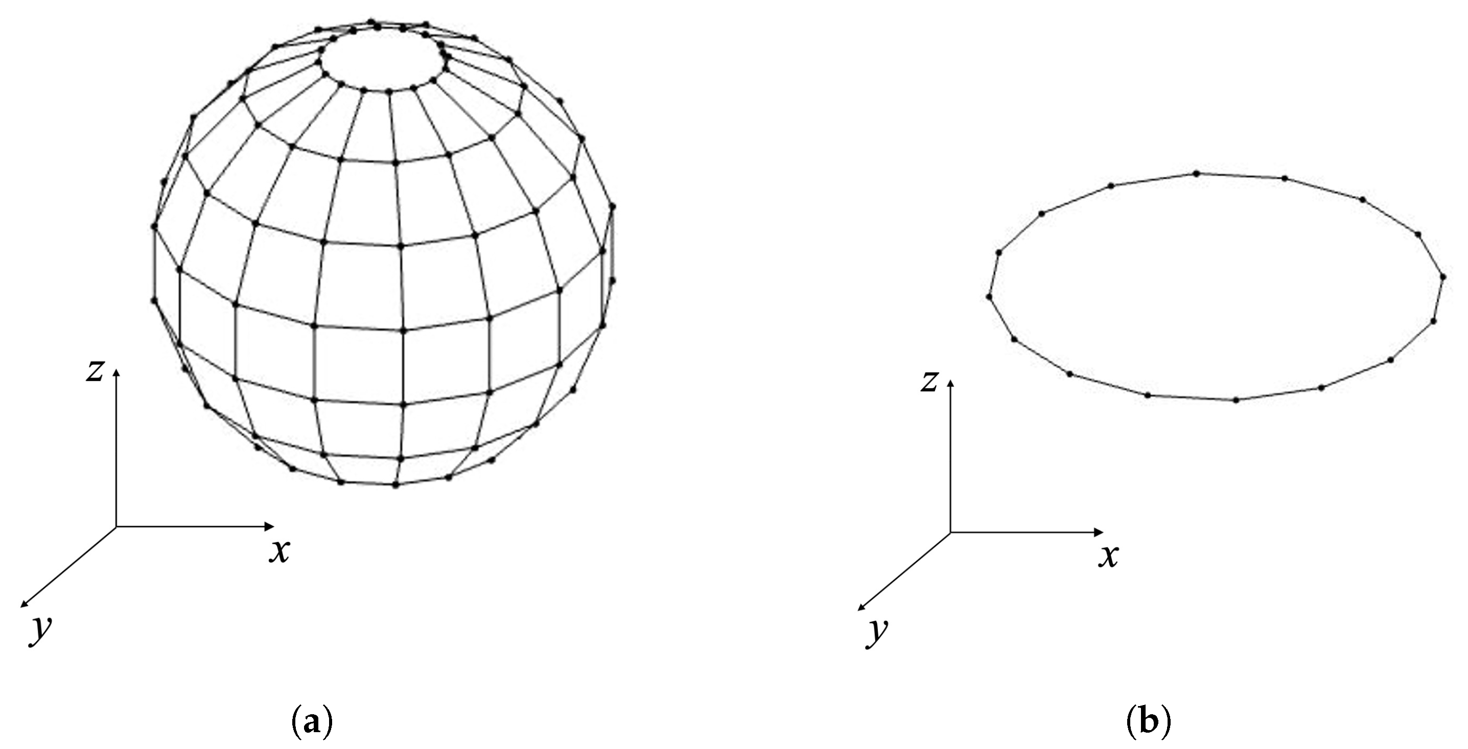
Figure 1. (a) Gaussian sampling grids for three-dimensional (3D) wave field information. (b) proposed circular array for two-dimensional (2D) wave field information when N = 8 .
Applsci 12 10245 g001
Figure 2. Proposed active noise control system based on the use of a single circular array with a quiet zone (blue region).
Applsci 12 10245 g002
Figure 3. Wave field reproduction error and variances with respect to r r e f . (a) Average wave field reproduction error. (b) Variance.
Applsci 12 10245 g003
Figure 4. (a) Desired wave field. (b) Wave field reproduction based on the use of a circular array. Wave field reproduction error at (c) r r e f = 0.4 m and (d) r r e f = R m i c .
Applsci 12 10245 g004
Figure 5. Wave field reproduction error and variance with respect to the radii of the microphone and loudspeaker array. (a,c) Average wave field reproduction error. (b,d) Variance.
Applsci 12 10245 g005
Figure 6. Block diagram of adaptive feedback FxLMS.
Applsci 12 10245 g006
Figure 7. Average noise reduction and variance with respect to frequency at different radii of microphones and loudspeaker arrays. (a,c) Average noise reduction. (b,d) Variance.
Applsci 12 10245 g007
Figure 8. (ac) Residual wave fields and (d) average noise reduction spectrum.
Applsci 12 10245 g008
Figure 9. Average noise reduction with respect to the noise source angle. According to the change of R m i c (a) and R s (b).
Applsci 12 10245 g009
Figure 10. (a) Experimental geometry and (b) measurement points.
Applsci 12 10245 g010
Figure 11. Experimental setup, (ac) cases 1–3.
Applsci 12 10245 g011
Figure 12. Experimental and simulation noise reduction performance. (a,c,e) Experimental cases 1, 2, and 3, respectively, and (b,d,f) simulation cases 1, 2, and 3, respectively.
Applsci 12 10245 g012
Table 1. Experimental Results.
Max (dB)Min (dB)Average (dB)
Case129.410.220.1
Case226.17.515.4
Case316.91.14.8
Publisher’s Note: MDPI stays neutral with regard to jurisdictional claims in published maps and institutional affiliations.