
Design and Analysis of Microchannels for Heat Dissipation of High-Energy VCSELs Based on Laser 3D Printing

Abstract
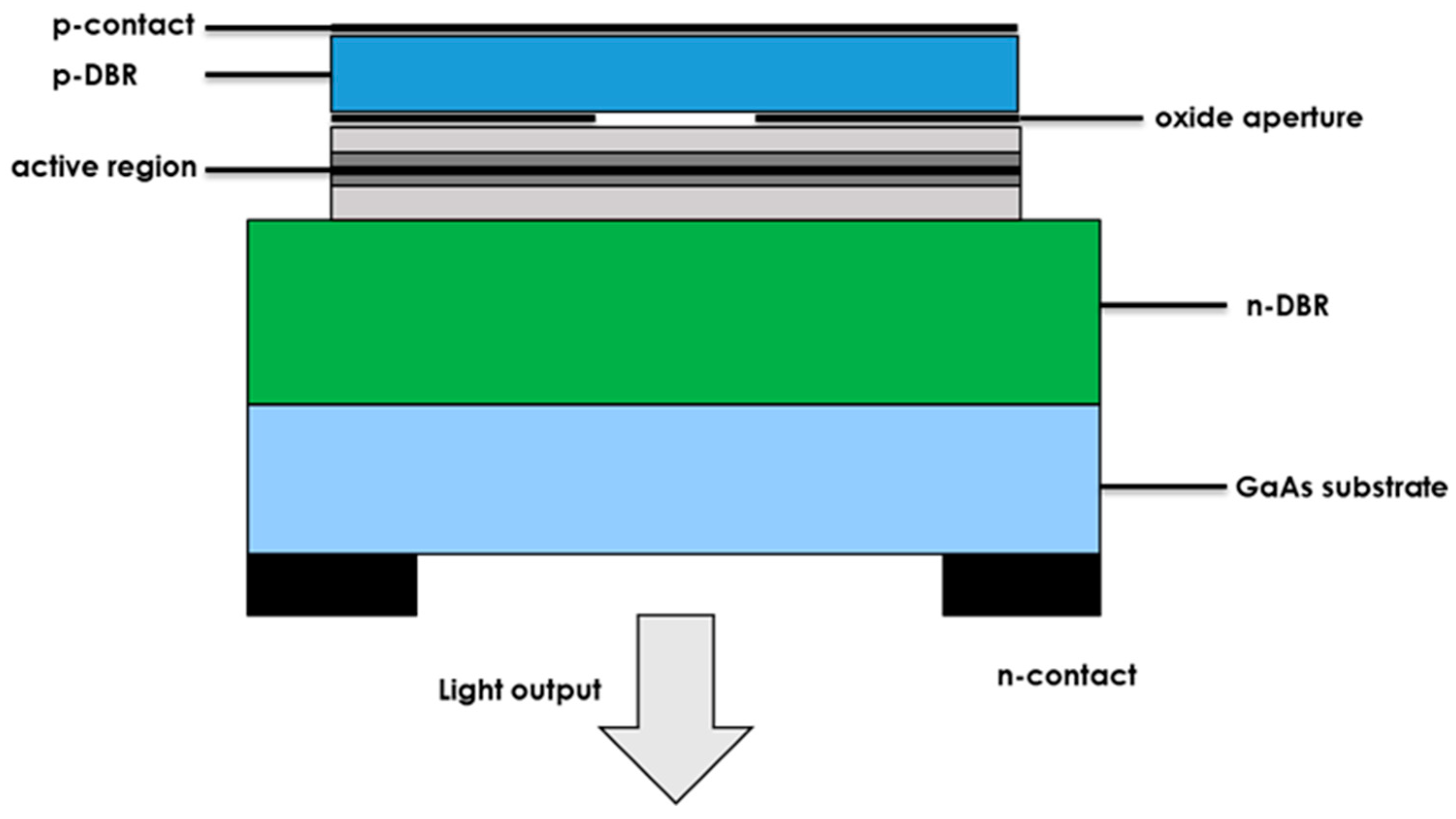
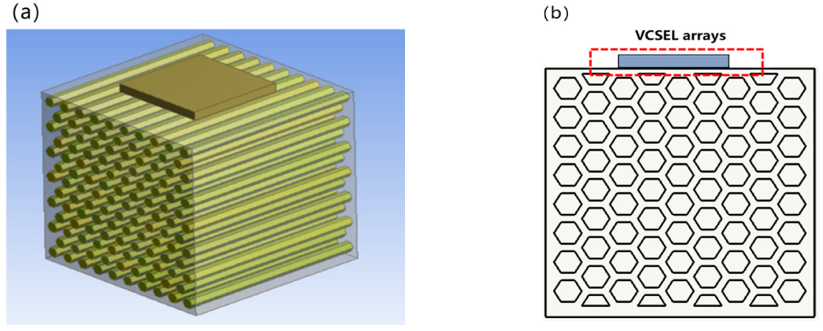
:1. Introduction
2. Micro-Channel Heat Sink Structure Design
3. Mathematical Model and Boundary Conditions
3.1. Mathematical Model
3.2. Boundary Conditions for Fluent Calculations
4. Numerical Simulation and Result Analysis
4.1. Influence of Coolant Flow on Thermal Resistance
4.2. Influence of Microchannel Hydraulic Diameter on Heat Dissipation Capacity
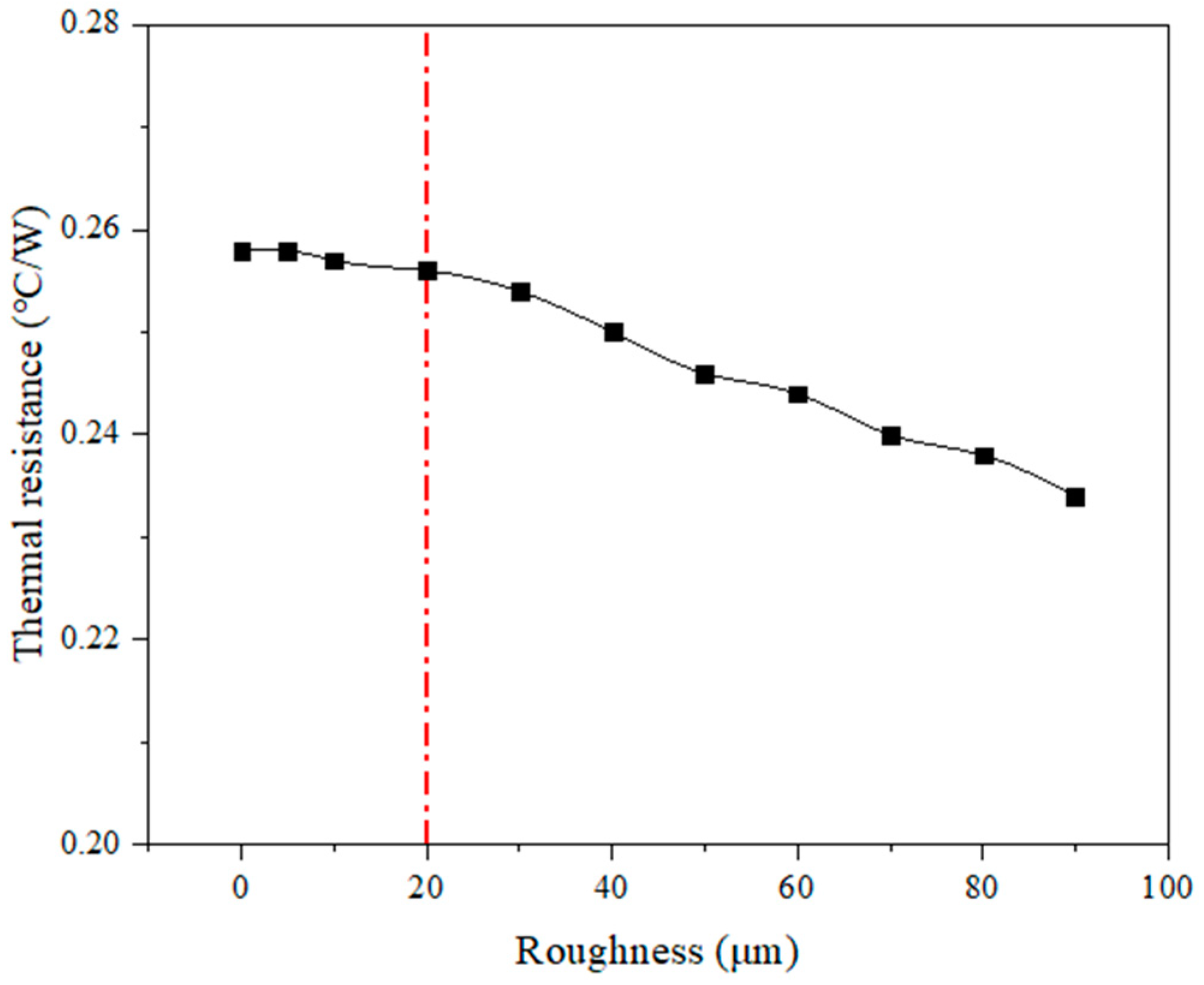
4.3. Effect of Microchannel Roughness on Heat Dissipation Capability
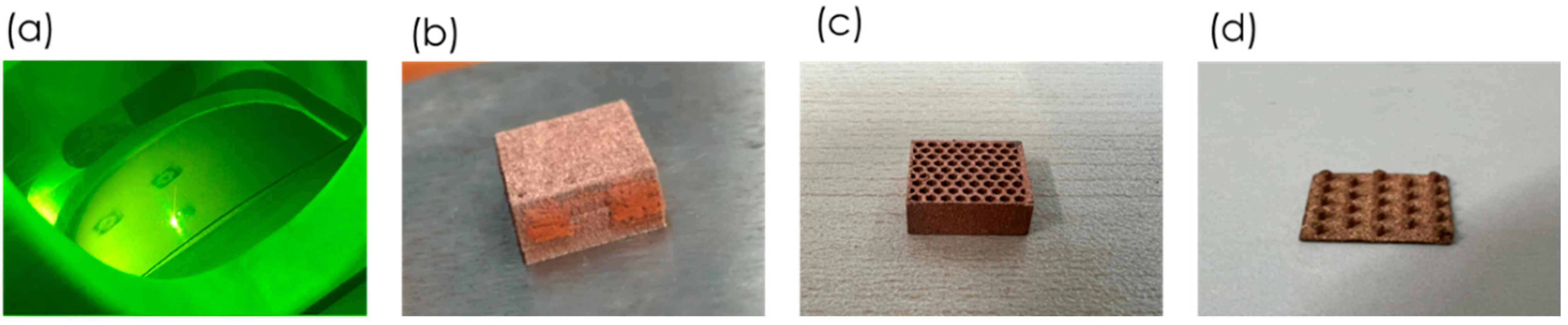
5. 3D Printing Microchannel Heat Sink
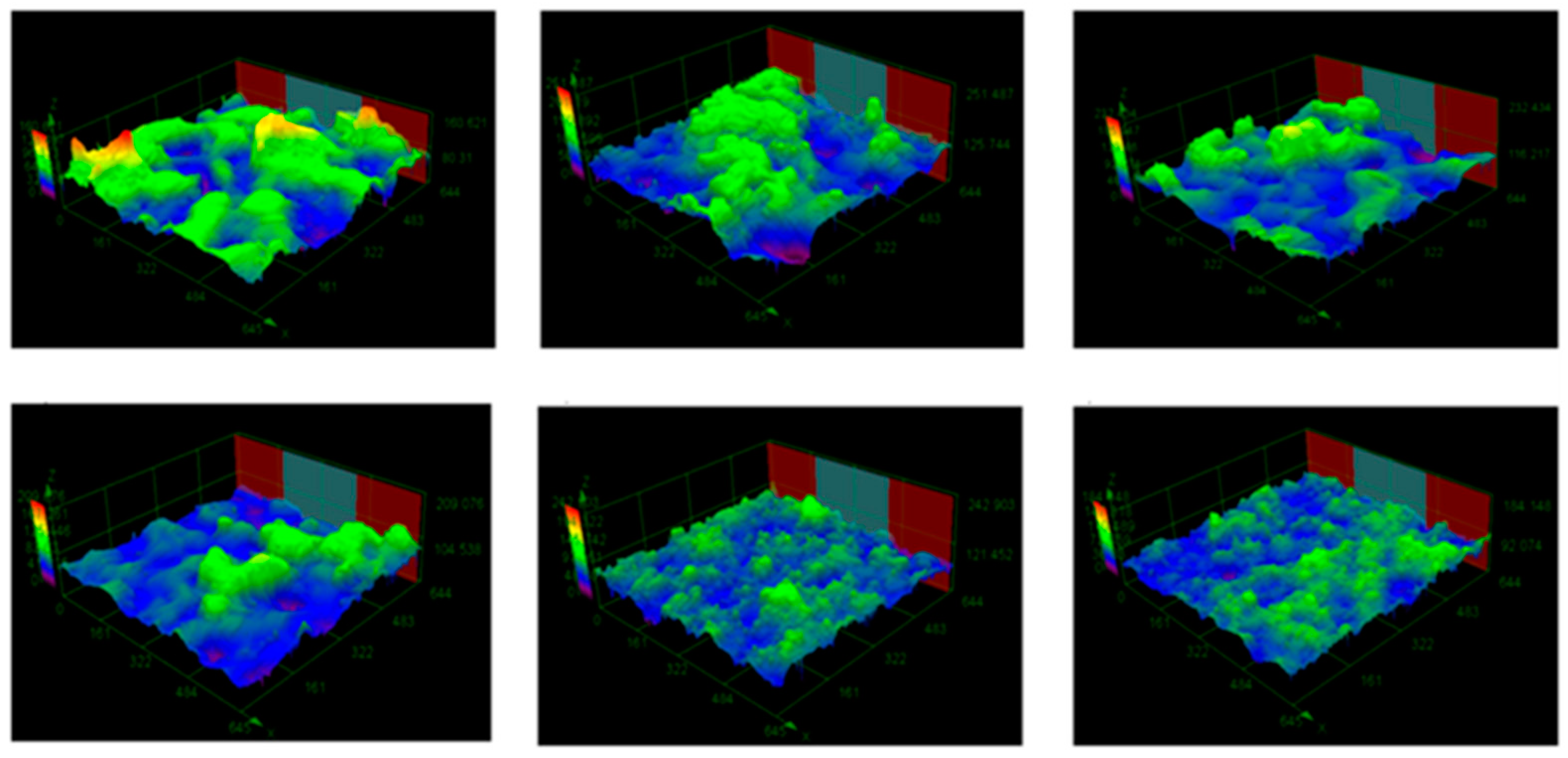
5.1. Roughness
5.2. Dimensional Accuracy
5.3. Thermal Conductivity
6. Conclusions
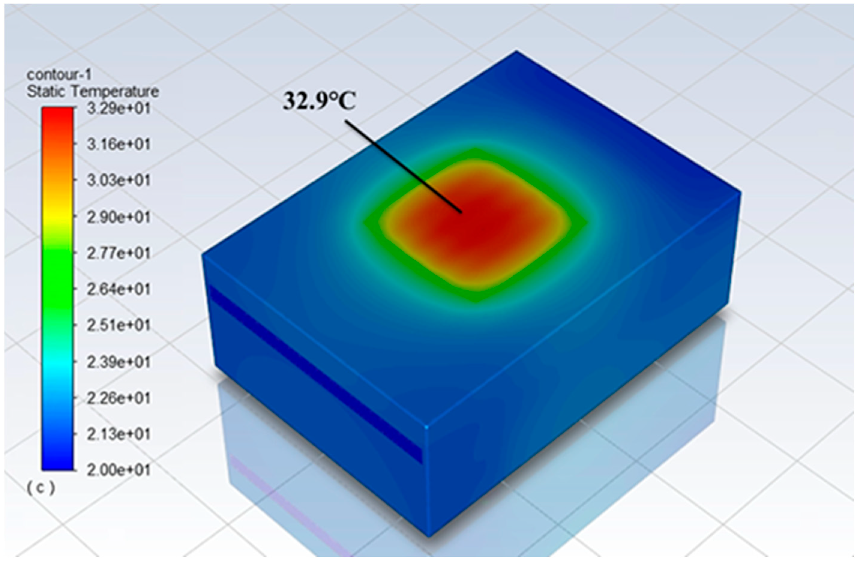
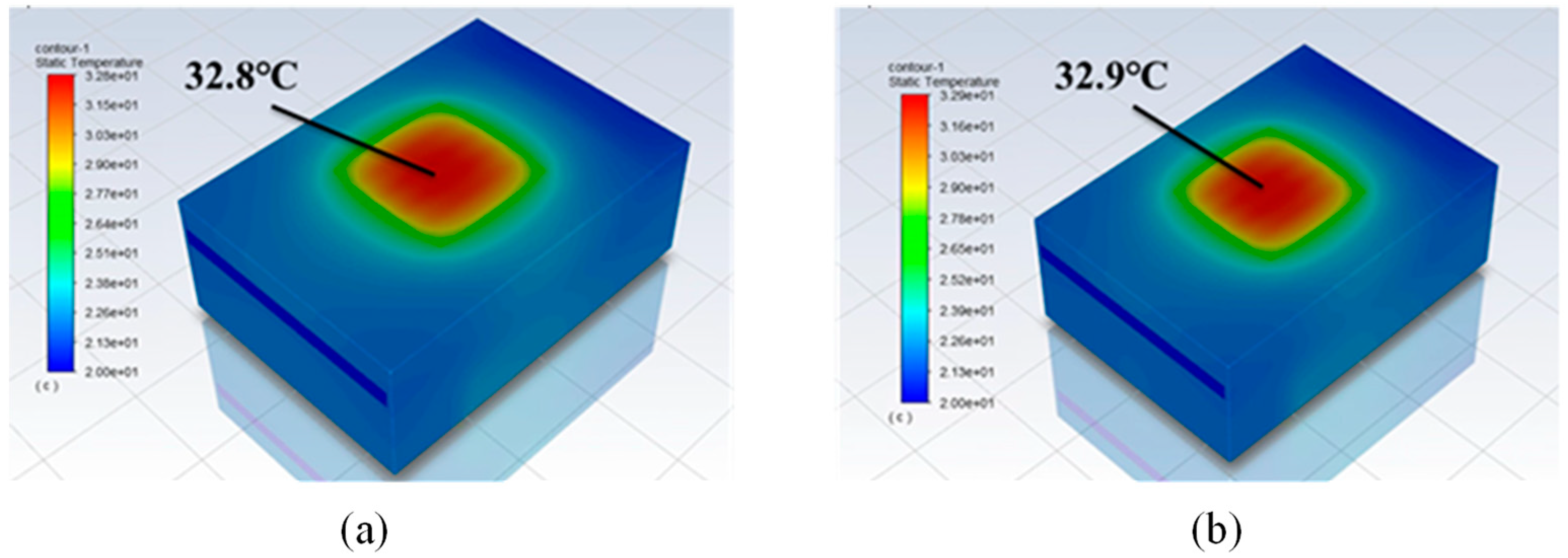
- Among the three structures of microchannel heat sinks of pin-fin, honeycomb, and double-layer reflow type, the double-layer reflow type has the lowest heat source surface temperature, the smallest chip thermal resistance, and the best heat dissipation effect. The optimal solution for the structural design of the double-layer reflow microchannel heat sink is obtained by comprehensively weighing the chip thermal resistance and the pipe pressure that the micro-channel can withstand: The hydraulic diameter is 0.5 mm, the coolant flow rate is 24 L/h, and the chip thermal resistance is 0.258 °C/W.
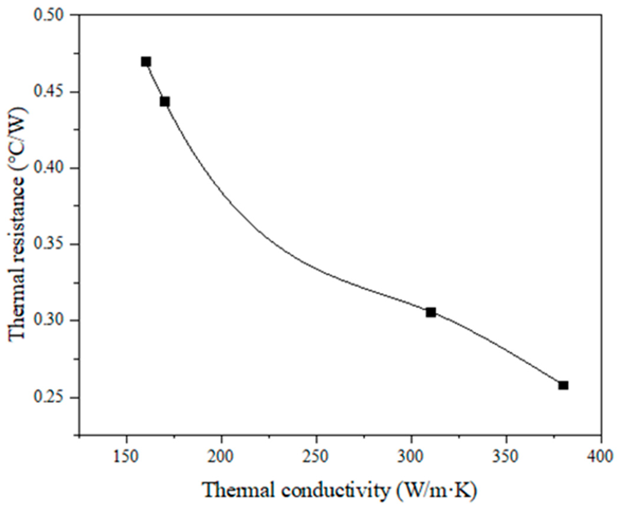
- The inner wall roughness of pure copper microchannel prepared by 3D printing technology is 7.08 μm, and the heat sink thermal resistance is reduced by 0.7% compared to that when the smooth channel wall is used. The deviation of microchannel diameter from the design size (500 μm) is −10 μm, and the heat sink thermal resistance is reduced by 0.8% compared to the theoretical value, which shows that the surface roughness and size deviation of 3D printed microchannel can be regarded as a beneficial factor to enhance heat dissipation. At present, the highest thermal conductivity achievable for laser 3D printed formed copper parts is 310 W/m-K, at which the maximum chip surface temperature is 35.3 °C and the heat sink thermal resistance is 0.306 °C/W, which can fully meet the chip (−45 °C~80 °C) operating temperature range.
Author Contributions
Funding
Conflicts of Interest
References
- Ihe, K.; Koyama, M.; Zhen, J. Basic and Application of Surface Emission Laser; Co-Publication: Tokyo, Japan, 2002. [Google Scholar]
- Seurin, J.-F.; Ghosh, C.L.; Khalfin, V.; Miglo, A.; Xu, G.; Wynn, J.D.; Pradhan, P.; D’Asaro, L.A. High-power high-efficiency 2D VCSEL arrays. Proc. SPIE 2008, 6908, 690808–690822. [Google Scholar]
- Zhou, D.; Seurin, J.F.; Xu, G.; Zhao, P.; Xu, B.; Chen, T.; Van Leeuwen, R.; Matheussen, J.; Wang, Q.; Ghosh, C. Progress on high-power high-brightness VCSELs and applications. Proc. SPIE Int. Soc. Opt. Eng. 2015, 9381, 93810B. [Google Scholar]
- Tuckerman, D.B.; Pease, R. High-performance heat sinking for VLSI. IEEE Electron. Device Lett. 1981, 2, 126–129. [Google Scholar] [CrossRef]
- Vafai, K.; Zhu, L.U. Analysis of two-layered micro-channel heat sink concept in electronic cooling. Int. J. Heat Mass Transf. 1999, 42, 2287–2297. [Google Scholar] [CrossRef]
- Yadav, V.; Kumar, R.; Narain, A. Mitigation of flow maldistribution in parallel microchannel heat sink. IEEE Trans. Compon. Packag. Manuf. Technol. 2019, 9, 247–261. [Google Scholar] [CrossRef]
- Qiu, T.W.; Liu, M.; Liu, Y.; Zhang, Y.; Jin, Z.J. Development of a new porous copper microchannel heat sink. Cryog. Supercond. 2020, 48, 85–89. [Google Scholar]
- Qiu, T.W.; Liu, M.; Liu, Y.; Zhang, Y.; Jin, Z.J. Experimental study on heat sink and heat dissipation performance of novel porous Copper microchannel. Therm. Sci. Technol. 2020, 19, 339–346. [Google Scholar]
- Abo-Zahhad, E.M.; Ookawara, S.; Radwan, A.; Elkady, M.F.; El-Shazly, A.H. Optimization of stepwise varying width microchannel heat sink for high heat flux applications. Case Stud. Therm. Eng. 2020, 18, 100587. [Google Scholar] [CrossRef]
- Xie, H.; Yang, B.; Zhang, S.; Song, M. Research on the mechanism of heat transfer enhancement in microchannel heat sinks with micropin fins. Int. J. Energy Res. 2020, 44, 3049–3065. [Google Scholar] [CrossRef]
- Chen, R.; Tang, S. Simulation of heat transfer performance of double-layer trapezoidal microchannel based on pyramidal disturbance structure. Chem. Ind. Eng. Prog. 2020, 39, 19–25. (In Chinese) [Google Scholar]
- Liu, F.; Wu, W.H.; Yang, Y.Q.; Wang, D.; Song, C.H. Manufacture of composition gradient material part by selective laser melting. Opt. Precis. Eng. 2020, 28, 1510–1518. [Google Scholar] [CrossRef]
- Yan, A.R.; Yang, T.T.; Wang, Y.L.; Du, Y.; Ma, Z.H.; Wang, Z.Y. Forming Process and High-temperature Mechanical Properties of IN718 Superalloy by Selective Melting with Variable Energy Laser. Opt. Precis. Eng. 2015, 23, 1695–1704. [Google Scholar] [CrossRef]
- Yan, A.R.; Liu, X.S.; Wang, Z.Y.; He, D.Y. Forming Process and Thermophysical Properties of W-Ni-Cu by Selective Laser Melting. Opt. Precis. Eng. 2019, 27, 1024–1032. [Google Scholar] [CrossRef]
- Neugebauer, R.; Müller, B.; Gebauer, M.; Töppel, T. Additive manufacturing boosts efficiency of heat transfer components. Assem. Autom. 2011, 31, 344–347. [Google Scholar] [CrossRef]
- Silbernagel, C.; Gargalis, L.; Ashcroft, I.; Hague, R.; Galea, M.; Dickens, P. Electrical resistivity of pure copper processed by medium-powered laser powder bed fusion additive manufacturing for use in electromagnetic applications. Addit. Manuf. 2019, 29, 100831. [Google Scholar] [CrossRef]
- Taha, B.; Patil, S.; Dennis, B.H. Design and Manufacturing of Topology Optimized Heat sinks made of Copper using 3D printing. In Proceedings of the International Manufacturing Science and Engineering Conference (MSEC), Virtual, Online, 21–25 June 2021. [Google Scholar]
- Sheng, Y. Research on 3D Printing Microchannel Heat Dissipation and Network Data Management Platform. Master’s Thesis, University of Electronic Science and Technology, Chengdu, China, June 2018. [Google Scholar]
- Liu, R.K.; Wang, C.C.; Li, C.C. Review of Thermal Dissipation Methods of High-power Semiconductor Lasers. Appl. Opto-Electron. Technol. 2019, 34, 1–6, 39. [Google Scholar]
- Fan, Y.P.; Shen, Z.B.; Li, P.; Zhang, J.; Liu, H. Improving the forming quality of laser dynamic flexible micro-bulging by laser pre-shocking. Opt. Precis. Eng. 2022, 30, 584–593. [Google Scholar] [CrossRef]
- Chen, T.Y.; Gu, M.F. Stoma suppression of laser sintering conductive circuit. Opt. Precis. Eng. 2020, 28, 1958–1966. [Google Scholar] [CrossRef]


| Type | Calculation Conditions |
|---|---|
| Chip Heat Source | 100 W |
| Photovoltaic conversion efficiency | 50% |
| Chip Size | 5 × 5 × 0.5 mm |
| Chip Materials | GaAs |
| Cooling mass | Deionized water |
| Heat sink size | 10 × 10 mm |
| Heat sink materials | Oxygen-free copper |
Publisher’s Note: MDPI stays neutral with regard to jurisdictional claims in published maps and institutional affiliations. |
© 2022 by the authors. Licensee MDPI, Basel, Switzerland. This article is an open access article distributed under the terms and conditions of the Creative Commons Attribution (CC BY) license (https://creativecommons.org/licenses/by/4.0/).
Share and Cite
Yan, A.; Liu, X.; Wang, X.; Wang, Z. Design and Analysis of Microchannels for Heat Dissipation of High-Energy VCSELs Based on Laser 3D Printing. Appl. Sci. 2022, 12, 10205. https://doi.org/10.3390/app122010205
Yan A, Liu X, Wang X, Wang Z. Design and Analysis of Microchannels for Heat Dissipation of High-Energy VCSELs Based on Laser 3D Printing. Applied Sciences. 2022; 12(20):10205. https://doi.org/10.3390/app122010205
Chicago/Turabian StyleYan, Anru, Xu Liu, Xiaobo Wang, and Zhiyong Wang. 2022. "Design and Analysis of Microchannels for Heat Dissipation of High-Energy VCSELs Based on Laser 3D Printing" Applied Sciences 12, no. 20: 10205. https://doi.org/10.3390/app122010205
APA StyleYan, A., Liu, X., Wang, X., & Wang, Z. (2022). Design and Analysis of Microchannels for Heat Dissipation of High-Energy VCSELs Based on Laser 3D Printing. Applied Sciences, 12(20), 10205. https://doi.org/10.3390/app122010205