
Mechanical Strength Study of a Cranial Implant Using Computational Tools


 ,
,  ,
,  and
and 
Abstract
:1. Introduction
2. Materials and Methods
2.1. PEEK Viscoplasticity
2.2. PEEK Fracture Model
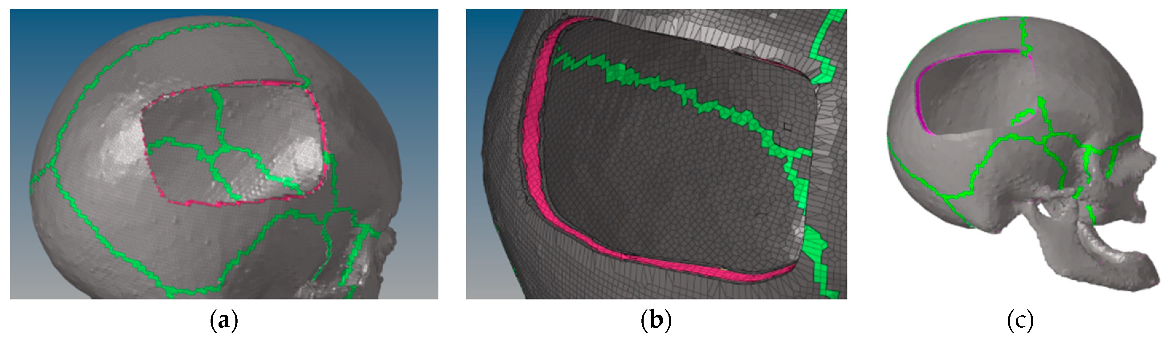
2.3. Skull Defect Creation and New Mesh
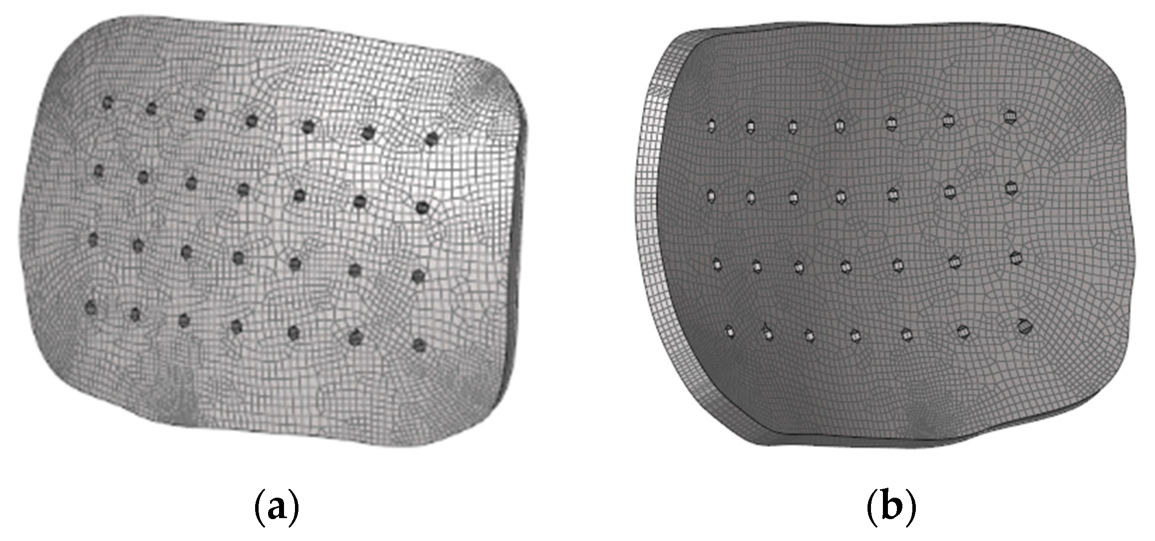
2.4. Implant Geometry and Mesh
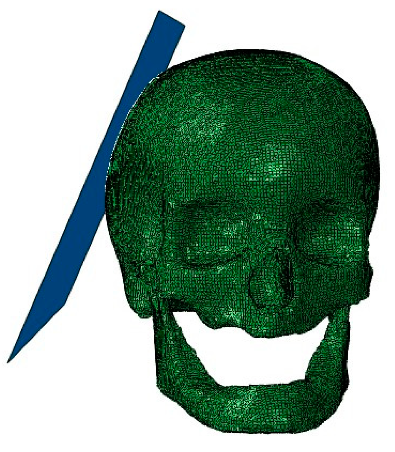
2.5. Head Model and Implant
2.6. Numerical Modeling Strategies
2.6.1. Fixation Method
2.6.2. Numerical Modeling Strategies
2.6.3. Case Study I
2.6.4. Case Study II
- pressure;
- shear stress;
- von Mises stress;
- strain.
3. Results and Discussion
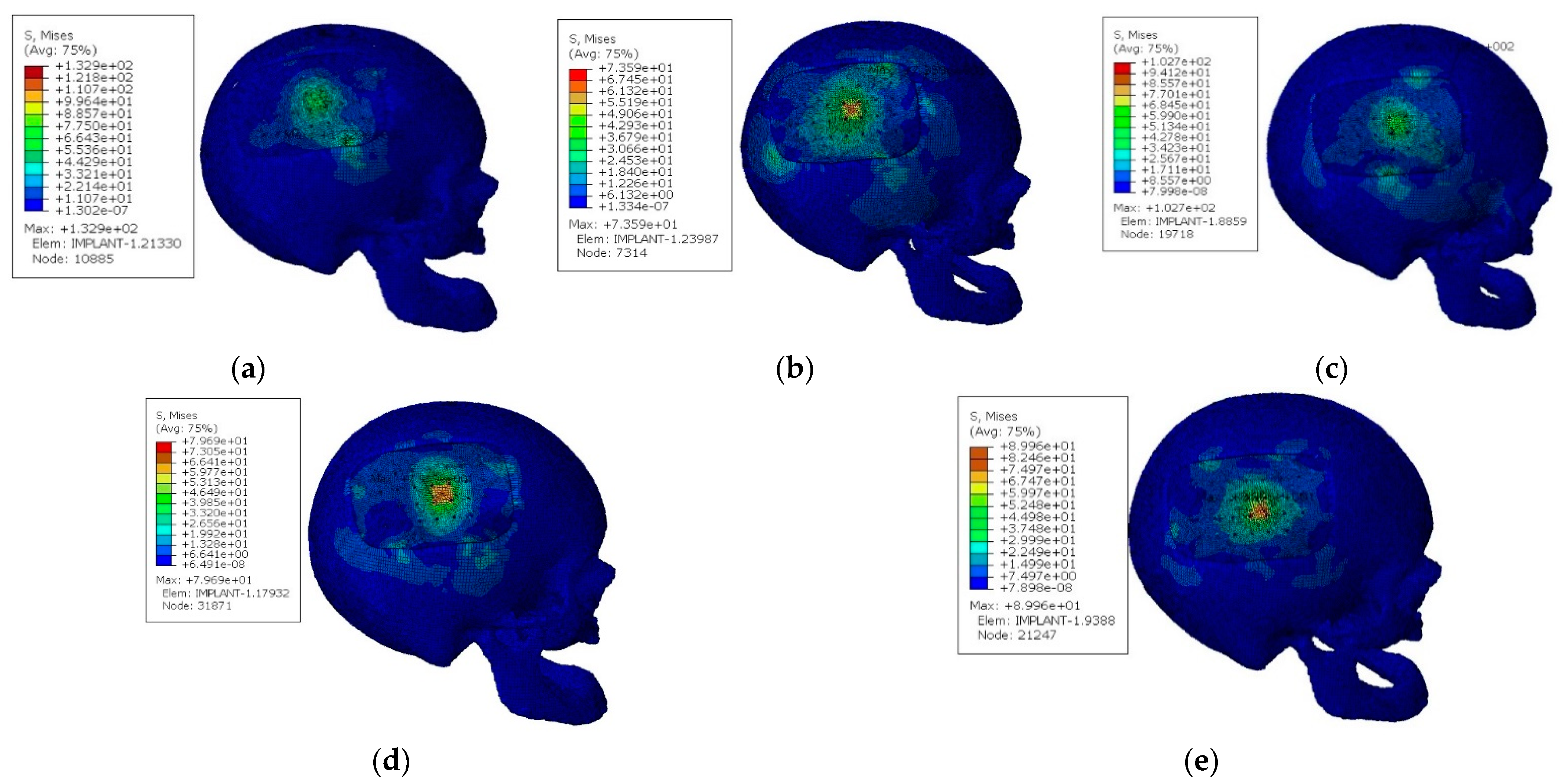
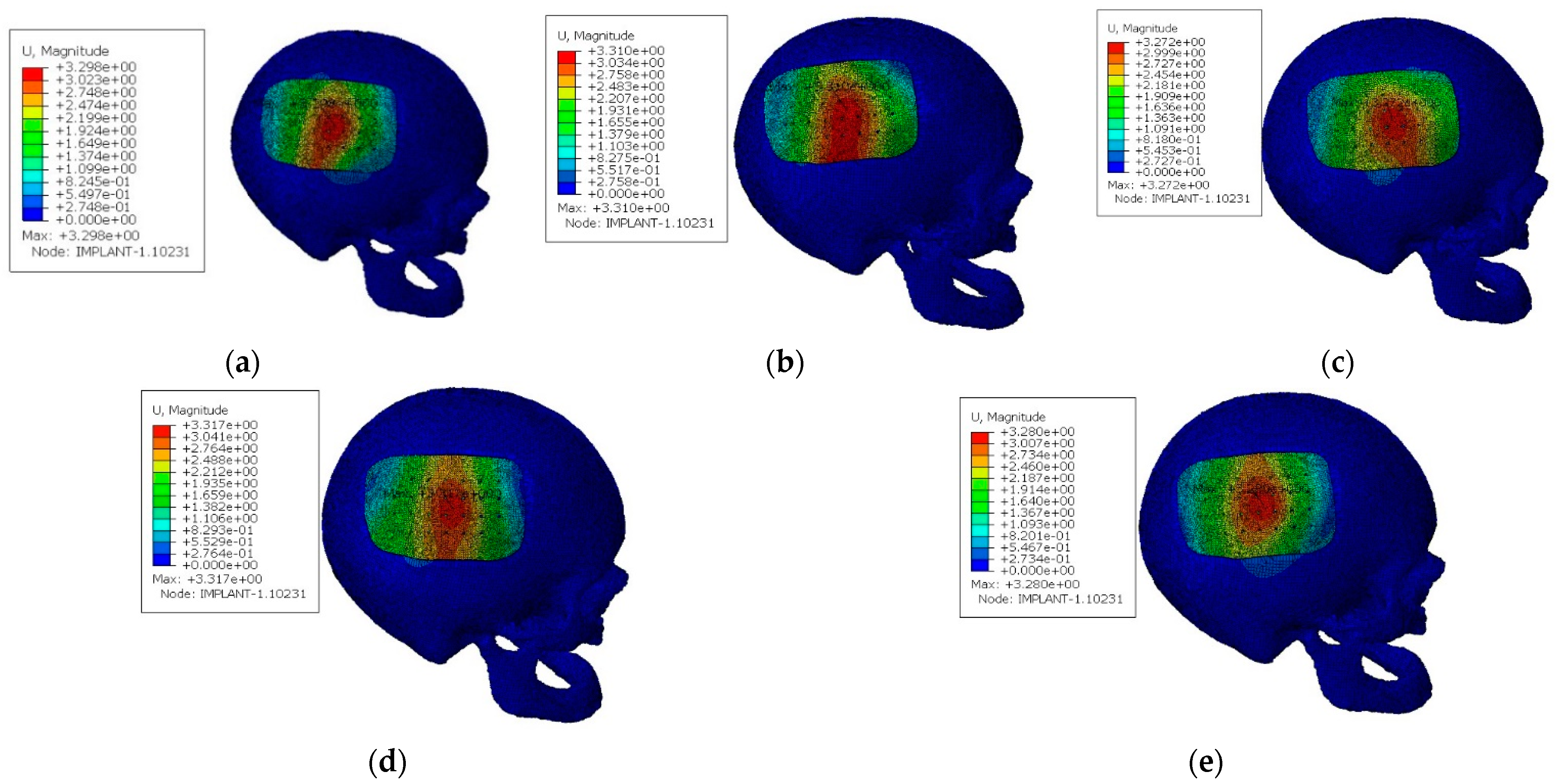
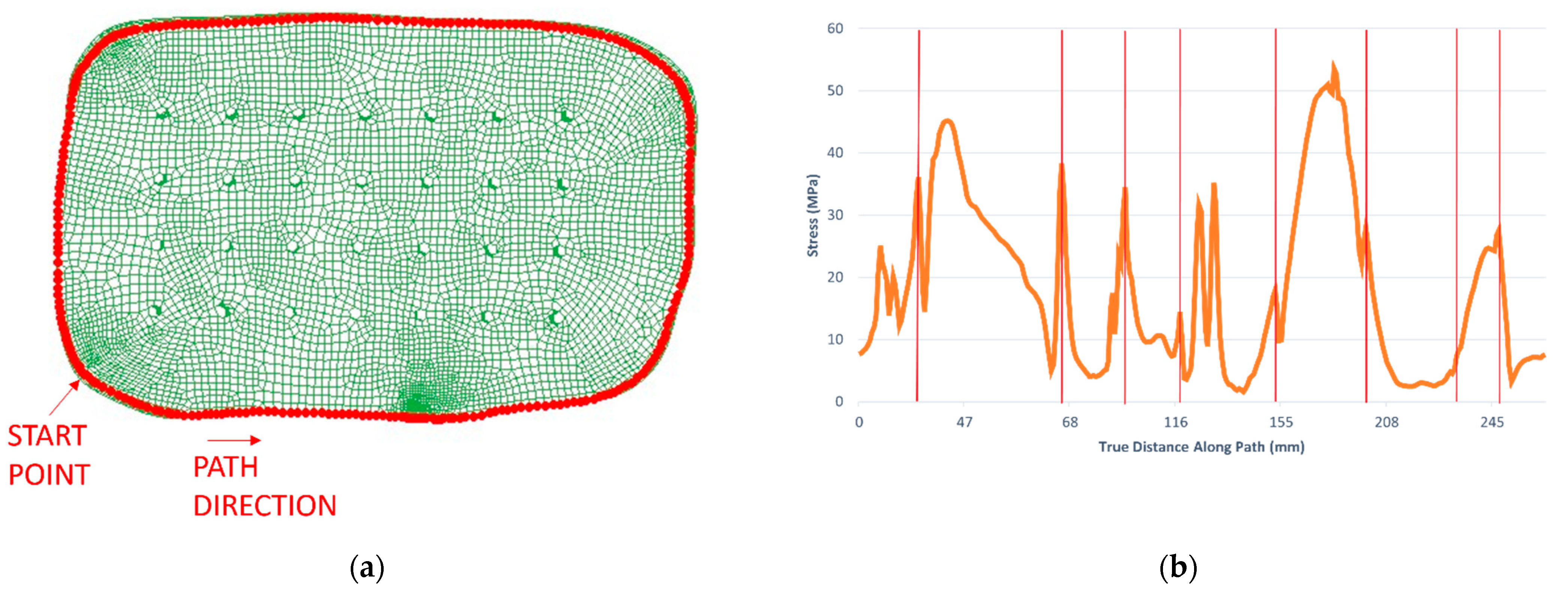
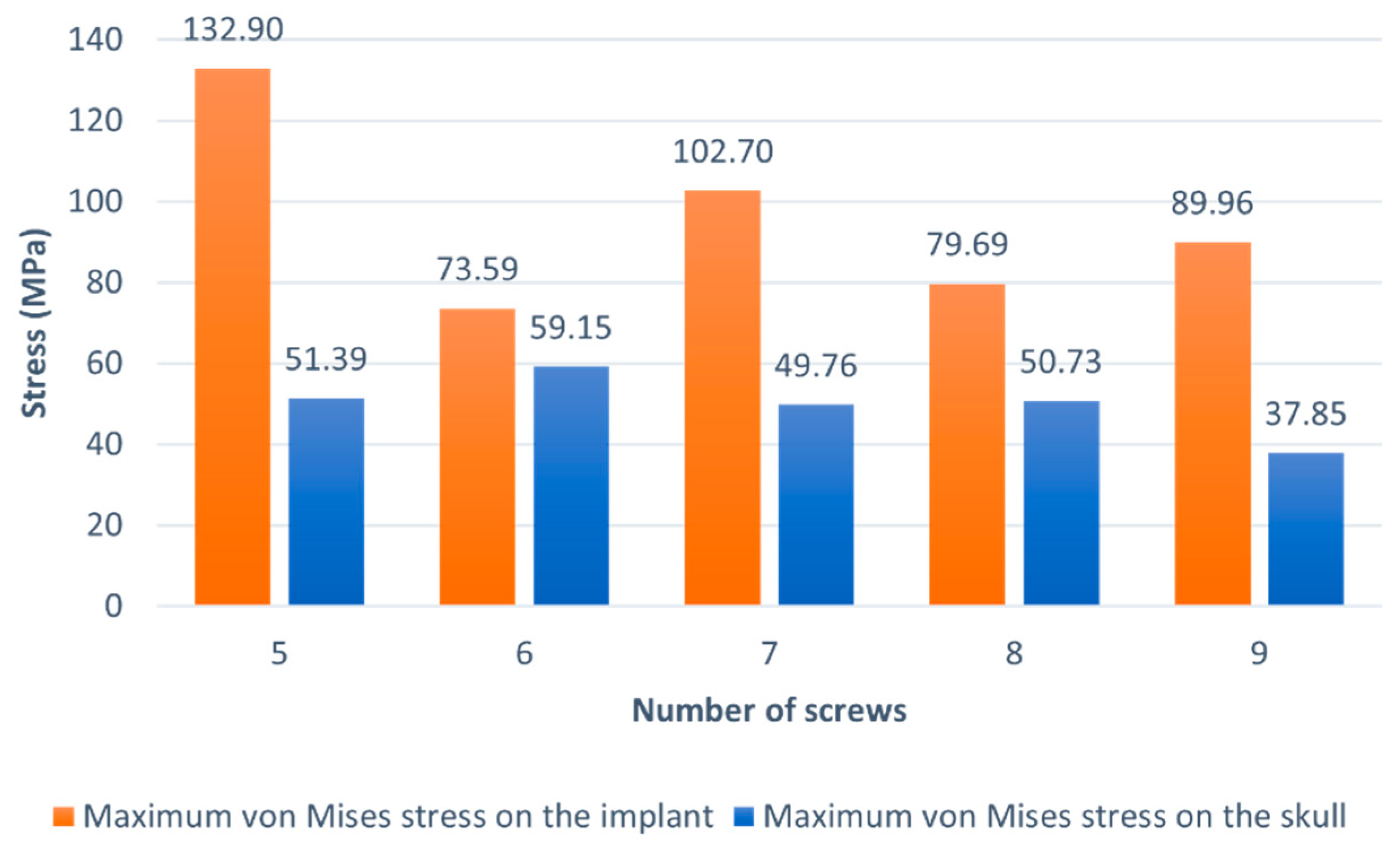
3.1. Case Study I
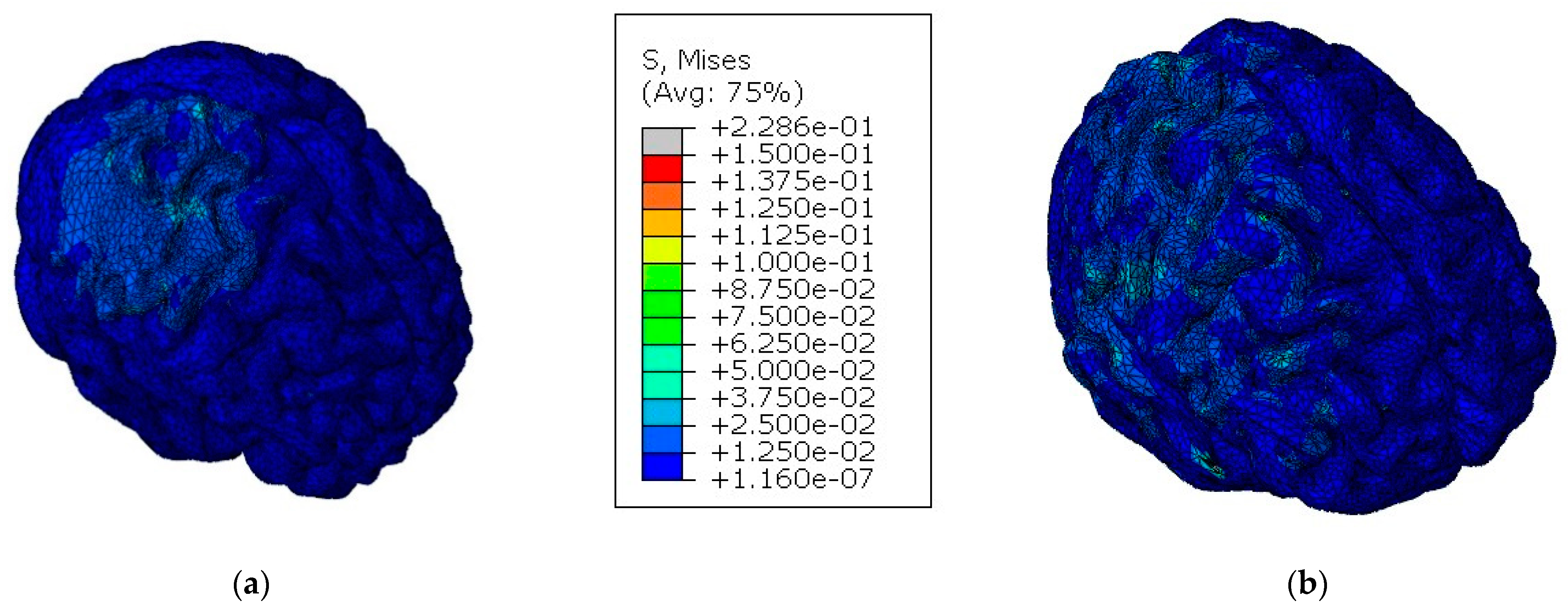
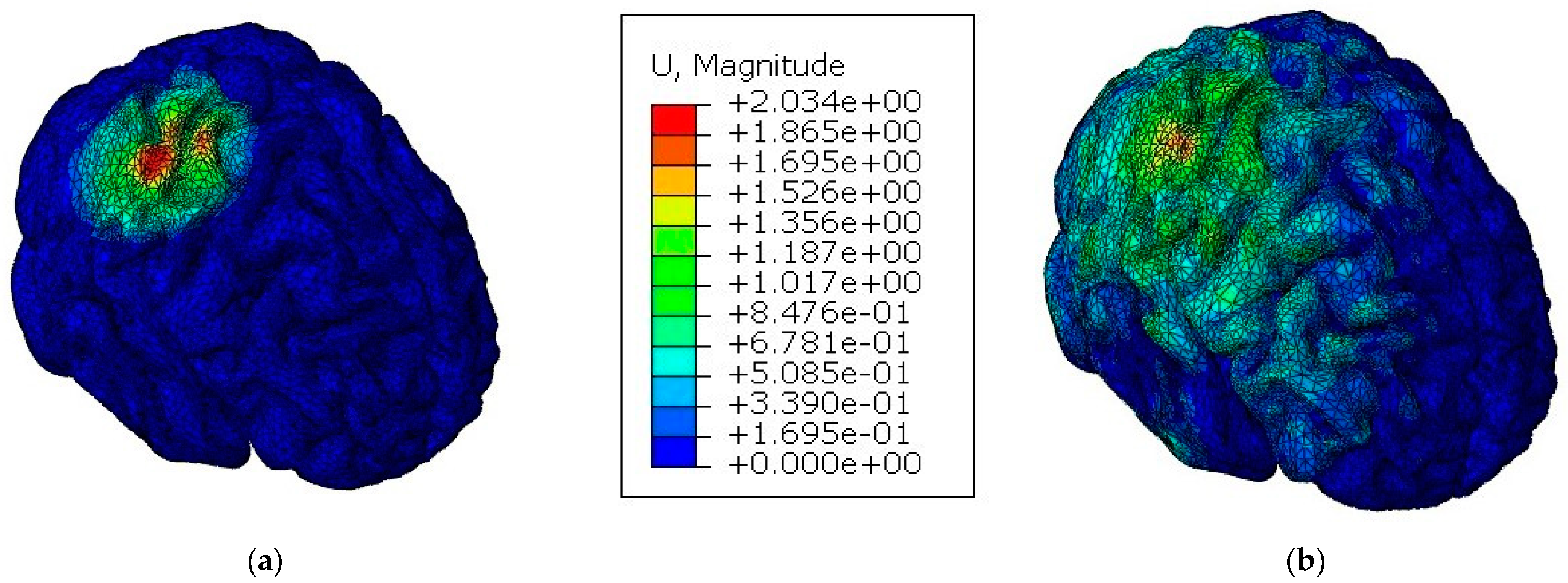
3.2. Case Study II
4. Conclusions
- a parametric study which had the purpose of finding the best configuration of fixation screws, in terms of number, that optimized the mechanical performance of the model and the structural integrity of the implant;
- a comparative study between a model with a cranial implant and another with an integral skull to evaluate the implant’s capacity to protect the brain against TBI.
Author Contributions
Funding
Institutional Review Board Statement
Informed Consent Statement
Data Availability Statement
Conflicts of Interest
References
- Becker, C. Skull: Anatomy, structure, bones, quizzes. Available online: https://www.kenhub.com/en/library/anatomy/the-skull (accessed on 1 November 2021).
- Evans, K. Physiology of cortical and trabecular bone. In The Diagnosis and Treatment of Osteoporosis; Van-Griner: Ohio, OH, USA, 2012; pp. 12–27. [Google Scholar]
- Ptak, M.; Ratajczak, M.; Kwiatkowski, A.; Sawicki, M.; Wilhelm, J.; Fernandes, F.A.; Druszcz, A. Investigation of biomechanics of skull structures damages caused by dynamic loads. Acta Bioeng. Biomech. 2018, 20, 143–150. [Google Scholar] [CrossRef]
- Garcia-Gonzalez, D.; Jayamohan, J.; Sotiropoulos, S.N.; Yoon, S.H.; Cook, J.; Siviour, C.R.; Arias, A.; Jérusalem, A. On the mechanical behaviour of PEEK and HA cranial implants under impact loading. J. Mech. Behav. Biomed. Mater. 2017, 69, 342–354. [Google Scholar] [CrossRef]
- Huys, S.E.F.; van Gysel, A.; Mommaerts, M.Y.; Sloten, J.V. Evaluation of Patient-Specific Cranial Implant Design Using Finite Element Analysis. World Neurosurg. 2021, 148, 198–204. [Google Scholar] [CrossRef]
- Bonda, D.; Manjila, S.; Selman, W.; Dean, D. The Recent Revolution in the Design and Manufacture of Cranial Implants: Modern Advancements and Future Directions. Physiol. Behav. 2016, 176, 139–148. [Google Scholar] [CrossRef] [Green Version]
- Ma, H.; Suonan, A.; Zhou, J.; Yuan, Q.; Liu, L.; Zhao, X.; Lou, X.; Yang, C.; Li, D.; Zhang, Y.G. PEEK (Polyether-ether-ketone) and its composite materials in orthopedic implantation. Arab. J. Chem. 2021, 14, 102977. [Google Scholar] [CrossRef]
- Zhang, J.; Tian, W.; Chen, J.; Yu, J.; Zhang, J.; Chen, J. The application of polyetheretherketone (PEEK) implants in cranioplasty. Brain Res. Bull. 2019, 153, 143–149. [Google Scholar] [CrossRef]
- Najeeb, S.; Zafar, M.S.; Khurshid, Z.; Siddiqui, F. Applications of polyetheretherketone (PEEK) in oral implantology and prosthodontics. J. Prosthodont. Res. 2016, 60, 12–19. [Google Scholar] [CrossRef] [PubMed]
- Alqurashi, H.; Khurshid, Z.; Syed, A.U.Y.; Habib, S.R.; Rokaya, D.; Zafar, M.S. Polyetherketoneketone (PEKK): An emerging biomaterial for oral implants and dental prostheses. J. Adv. Res. 2021, 28, 87–95. [Google Scholar] [CrossRef] [PubMed]
- Zafar, M.S. Prosthodontic Applications of Polymethyl Methacrylate (PMMA): An Update. Polymers 2020, 12, 2299. [Google Scholar] [CrossRef]
- Huang, M.T.; Juan, P.K.; Chen, S.Y.; Wu, C.J.; Wen, S.C.; Cho, Y.C.; Huang, M.S.; Chou, H.H.; Ou, K.L. The potential of the three-dimensional printed titanium mesh implant for cranioplasty surgery applications: Biomechanical behaviors and surface properties. Mater. Sci. Eng. C 2018, 97, 412–419. [Google Scholar] [CrossRef] [PubMed]
- Elhattab, K.; Sikder, P.; Walker, J.M.; Bottino, M.C.; Bhaduri, S.B. Fabrication and evaluation of 3-D printed PEEK scaffolds containing Macropores by design. Mater. Lett. 2020, 263, 127227. [Google Scholar] [CrossRef]
- de Santis, R.; Russo, T.; Rau, J.V.; Papallo, I.; Martorelli, M.; Gloria, A. Design of 3d additively manufactured hybrid structures for cranioplasty. Materials 2021, 14, 181. [Google Scholar] [CrossRef] [PubMed]
- Roque, R.; Barbosa, G.F.; Guastaldi, A.C. Design and 3D bioprinting of interconnected porous scaffolds for bone regeneration. An additive manufacturing approach. J. Manuf. Process. 2021, 64, 655–663. [Google Scholar] [CrossRef]
- Jonkergouw, J.; van de Vijfeijken, S.E.; Nout, E.; Theys, T.; Van de Casteele, E.; Folkersma, H.; Depauw, P.R.; Becking, A.G. Outcome in patient-specific PEEK cranioplasty: A two-center cohort study of 40 implants. J. Cranio-Maxillofac. Surg. 2016, 44, 1266–1272. [Google Scholar] [CrossRef] [PubMed]
- Rashidi, A.; Adolf, D.; Karagiannis, D.; Melhem, O.B.; Luchtmann, M. Incidence and Risk Factors for Skull Implant Displacement After Cranial Surgery. World Neurosurg. 2019, 126, e814–e818. [Google Scholar] [CrossRef] [PubMed]
- Garcia-Gonzalez, D.; Rusinek, A.; Jankowiak, T.; Mechanical, A.A. Mechanical impact behavior of polyether-ether-ketone (PEEK). Compos. Struct. 2015, 124, 88–99. [Google Scholar] [CrossRef] [Green Version]
- Rae, P.J.; Brown, E.N.; Orler, E.B. The mechanical properties of poly(ether-ether-ketone) (PEEK) with emphasis on the large compressive strain response. Polymer 2007, 48, 598–615. [Google Scholar] [CrossRef]
- Johnson, G.R.; Cook, W.H. Fracture characteristics of three metals subjected to various strains, strain rates, temperatures and pressures. Eng. Fract. Mech. 1985, 21, 31–48. [Google Scholar] [CrossRef]
- Sobieraj, M.; Rimnac, C. Fracture, Fatigue, and Notch Behavior of PEEK. In PEEK Biomaterials Handbook; Elsevier: Amsterdam, Netherlands, 2012; pp. 61–73. [Google Scholar]
- Fernandes, F.A.O.; Tchepel, D.; de Sousa, R.J.A.; Ptak, M. Development and validation of a new finite element human head model: Yet another head model (YEAHM). Eng. Comput. 2018, 35, 477–496. [Google Scholar] [CrossRef]
- Migueis, G.F.J.; Fernandes, F.A.O.; Ptak, M.; Ratajczak, M.; de Sousa, R.J.A. Detection of bridging veins rupture and subdural haematoma onset using a finite element head model. Clin. Biomech. 2019, 63, 104–111. [Google Scholar] [CrossRef]
- Costa, J.M.C.; Fernandes, F.A.O.; de Sousa, R.J.A. Prediction of subdural haematoma based on a detailed numerical model of the cerebral bridging veins. J. Mech. Behav. Biomed. Mater. 2020, 111, 103976. [Google Scholar] [CrossRef]
- Barbosa, A.; Fernandes, F.A.O.; de Sousa, R.J.A.; Ptak, M.; Wilhelm, J. Computational modeling of skull bone structures and simulation of skull fractures using the YEAHM head model. Biology 2020, 9, 267. [Google Scholar] [CrossRef] [PubMed]
- Marcián, P.; Narra, N.; Borák, L.; Chamrad, J.; Wolff, J. Biomechanical performance of cranial implants with different thicknesses and material properties: A finite element study. Comput. Biol. Med. 2019, 109, 43–52. [Google Scholar] [CrossRef]
- Korolija, A. FE-Modeling of Bolted Joints in Structures; Linköping University: Linkoping, Sweden, 2012. [Google Scholar]
- Huth, H. Experimenal Determination of Fastener Flexibilities; Aircraft Division Saab-Scania AB: Linköping, Sweden, 1983. [Google Scholar]
- Schulz, B.W.; Lee, W.E.; Lloyd, J.D. Estimation, simulation, and experimentation of a fall from bed. J. Rehabil. Res. Dev. 2008, 45, 1227–1236. [Google Scholar] [CrossRef] [PubMed]
- Fahlstedt, M.; Baeck, K.; Halldin, P.; Van Der Sloten, J.; Goffin, J.; Depreitere, B.; Kleiven, S. Influence of impact velocity and angle in a detailed reconstruction of a bicycle accident. In Proceedings of the 2012 IRCOBI Conference Proceedings—International Research Council on the Biomechanics of Injury Conference, Dublin, Ireland, 12–14 September 2012; pp. 787–799. [Google Scholar]
- Tse, K.M.; Tan, L.B.; Lee, S.J.; Lim, S.P.; Lee, H.P. Investigation of the relationship between facial injuries and traumatic brain injuries using a realistic subject-specific finite element head model. Accid. Anal. Prev. 2015, 79, 13–32. [Google Scholar] [CrossRef]


| Thermoviscoplastic Behavior | |||||
| A (MPa) | B (MPa) | n | (s−1) | C | m |
| 132 | 10 | 1.2 | 0.01 | 0.034 | 0.7 |
| Elasticity | Other Physical Constants | ||||
| E0 (GPa) | ν | (kg/m3) | β | Cp (J/kg K) | Tm (K) |
| 3.6 | 0.4 | 1304 | 0.9 | 2180 | 614 |
| Force (Each Screw) [N] | Relative Plastic Displacement [mm] |
|---|---|
| 1000 | 0.000 |
| 2000 | 0.005 |
| 4000 | 0.020 |
| 6000 | 0.080 |
| 9000 | 0.225 |
| 11,000 | 0.400 |
| 13,000 | 0.640 |
| Parameter | Thresholds |
|---|---|
| Pressure | Criterion 1 |
| >235 kPa→injury | |
| <173 kPa→minor or no injury | |
| Shear stress | Criterion 2 |
| 11–16.5 kPa→severe injury | |
| Von Mises stress | Criterion 3 |
| >18 kPa→50% probability of moderate neurological lesions | |
| >38 kPa→50% probability of severe neurological lesions | |
| Criterion 4 | |
| ≥26 kPa→axonal damage | |
| Strain | Criterion 5 |
| >0.25→structural damage | |
| >0.20→functional damage | |
| >0.10→reversible damage |
| Criterion | Criterion Definition | Model With Implant | Model With Integral Skull |
|---|---|---|---|
| Criterion 1 | Injury | 0.29% | 5.88% |
| Minor or No Injury | 99.13% | 84.28% | |
| Criterion 2 | Severe Injury (Shear stress XY) | 0.010% | 0.018% |
| Severe Injury (Shear Stress XZ) | 0.002% | 0.025% | |
| Severe Injury (Shear Stress YZ) | 0.001% | 0.026% | |
| Criterion 3 | 50% Probability of Moderate Neurological Lesions | 2.47% | 1.84% |
| 50% Probability of Severe Neurological Lesions | 0.01% | 0.12% | |
| Criterion 4 | Axonal Damage | 0.40% | 0.48% |
| Criterion 5 | Reversible Damage | 0.35% | 0.49% |
| Functional Damage | 0.001% | 0.01% | |
| Axonal Damage | 0.001% | 0.01% |
Publisher’s Note: MDPI stays neutral with regard to jurisdictional claims in published maps and institutional affiliations. |
© 2022 by the authors. Licensee MDPI, Basel, Switzerland. This article is an open access article distributed under the terms and conditions of the Creative Commons Attribution (CC BY) license (https://creativecommons.org/licenses/by/4.0/).
Share and Cite
Santos, P.O.; Carmo, G.P.; Sousa, R.J.A.d.; Fernandes, F.A.O.; Ptak, M. Mechanical Strength Study of a Cranial Implant Using Computational Tools. Appl. Sci. 2022, 12, 878. https://doi.org/10.3390/app12020878
Santos PO, Carmo GP, Sousa RJAd, Fernandes FAO, Ptak M. Mechanical Strength Study of a Cranial Implant Using Computational Tools. Applied Sciences. 2022; 12(2):878. https://doi.org/10.3390/app12020878
Chicago/Turabian StyleSantos, Pedro O., Gustavo P. Carmo, Ricardo J. Alves de Sousa, Fábio A. O. Fernandes, and Mariusz Ptak. 2022. "Mechanical Strength Study of a Cranial Implant Using Computational Tools" Applied Sciences 12, no. 2: 878. https://doi.org/10.3390/app12020878
APA StyleSantos, P. O., Carmo, G. P., Sousa, R. J. A. d., Fernandes, F. A. O., & Ptak, M. (2022). Mechanical Strength Study of a Cranial Implant Using Computational Tools. Applied Sciences, 12(2), 878. https://doi.org/10.3390/app12020878