1. Introduction
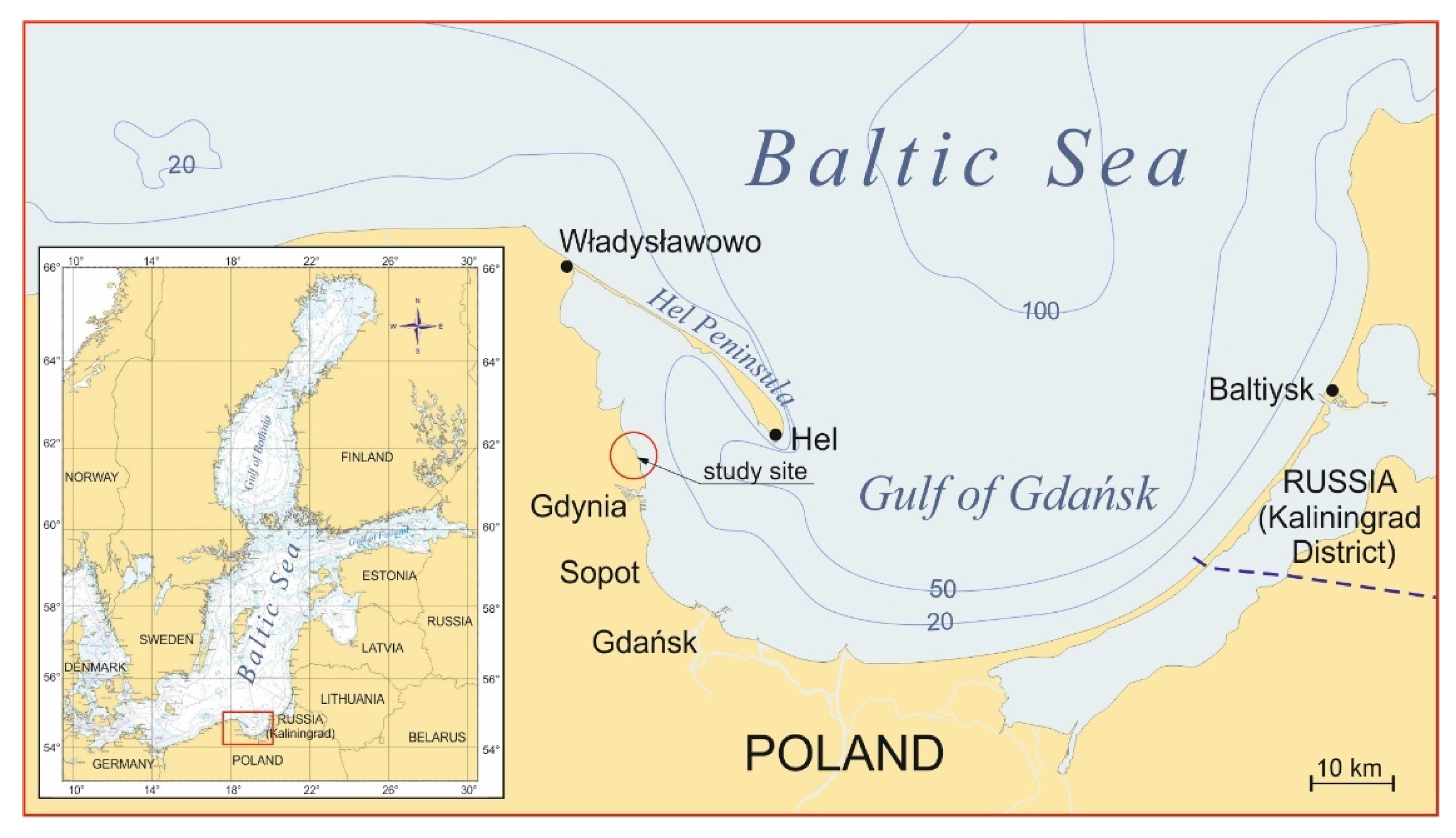
The seashore section in the region of Babie Doły (northernmost district of Gdynia, see
Figure 1) has recently been the subject of interest on the part of the media and representatives of social movements. The problem was critically reported by representatives of social movements within the broadcasts on local TV and radio. On the next day (27 April 2021), it was commented on by the Maritime Office in Gdynia (
https://www.umgdy.gov.pl/?p=42355 (accessed on 29 April 2021)). The Maritime Office in Gdynia has been urged to take measures aimed at removing the coastal protection structure or at least clearing up the seashore section at KM 93.6–93.9, at which the rubble revetment is installed (
Figure 2). The objective of this study is to analyse the situation and to provide suggestions on how to deal with the structure in question.
Erosive processes cause serious engineering problems and require the implementation of protective measures. The phenomena of erosion and flooding resulting from specific hydraulic conditions occur both in the domain of coastal engineering and river engineering. Understanding of erosive processes requires a thorough identification of characteristics of the motion of water and sediments in the coastal zone [
1,
2] or in rivers (see, e.g., [
3,
4]). The solutions undertaken in order to mitigate the erosive threats depend on the features of local hydro- and litho-dynamic processes. In Poland, recently, these solutions need the acceptance of various entities (governmental institutions responsible for environmental protection, ecological associations and local authorities). Frequently, the aesthetics of existing or planned protective structures becomes important.
The solution of the problem encountered at the considered study site requires the analysis of archival data on shoreline position, namely the historical maps, as well as the theoretical modelling, focused on the calculation of sediment transport characteristics. Within the latter issue, both qualitative findings (direction of transport of sandy sediments along the shore) and quantitative results (annual rates of net longshore sediment transport) are important.
2. Materials and Methods
According to [
5], the dominant type of coast in this area is the cliffed coast, characterised—in contrast to the dune coast—by a very narrow beach (usually at the foot of inactive cliffs) or its complete absence (mostly at the foot of active cliffs). A clearly distinguishable coastal headland is located at the administrative boundary between the city of Gdynia and the commune of Kosakowo, i.e., in the vicinity of KM 93.4–93.5 (
Figure 3). A strip of beach stretches south of the headland, with a width decreasing from about 50 m in the immediate vicinity of the headland to disappear at a distance of about 350–400 m (near KM 93.0). To the northwest of the headland, the beach covers only a short (ca. 100 m) stretch of coast (
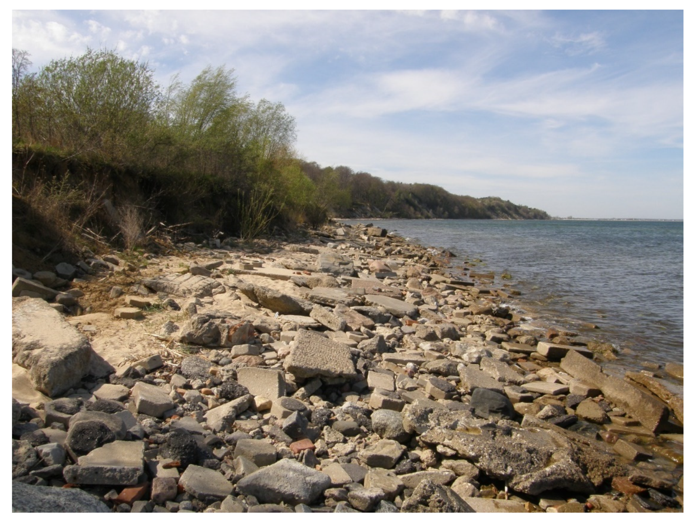
Figure 4), largely near the remains of hard coastal protection structures. At a distance of about 150 m northwest of the headland (KM 93.6), the seashore is protected by a revetment built of rubble concrete, approximately 300 m long (
Figure 5).
Most of the 30 analysed satellite images taken in 2005–2019 show sandy shallows of at least 50 m in width, measured from the coastline, located in the nearshore zone within several hundred meter long stretches of shore, adjacent to the headland from the south and from the north. In the “southern” section, these shallows usually appear as two distinct sandbars (at a distance of 40–70 m and 150–190 m from the coastline), whereas in the “northern” section, they assume irregular forms, sometimes with two less pronounced sandbars (20–40 m and 100–130 m from the coastline;
Figure 3). Except for the aforementioned location, with a relatively wide beach along the short stretch of shore immediately adjacent to the headland on the southern side, the analysed area is characterised by a very narrow beach or the absence thereof.
Coastline development in a historical context can be demonstrated using free images with GIS analysis (see [
6,
7]). In the presented specific case study, however, the analysis of the historical maps is carried out, supported by results of the sediment transport modelling. In particular, it is important to identify both the qualitative and quantitative features of transport of sandy sediments along the shore, namely its direction and annual rates. These characteristics are useful in understanding the shoreline evolution occurring at the site under consideration, and the role of the existing revetment.
The processes leading to the shoreline development are the result of sediment transport, which occurs in the immediate vicinity of the seashore, especially in the surf (breaker) zone, i.e., in water less than a few metres deep. Outside this zone, in deeper waters (several metres or more) and with typical wave conditions, sediment transport generated by waves is negligible [
8,
9].
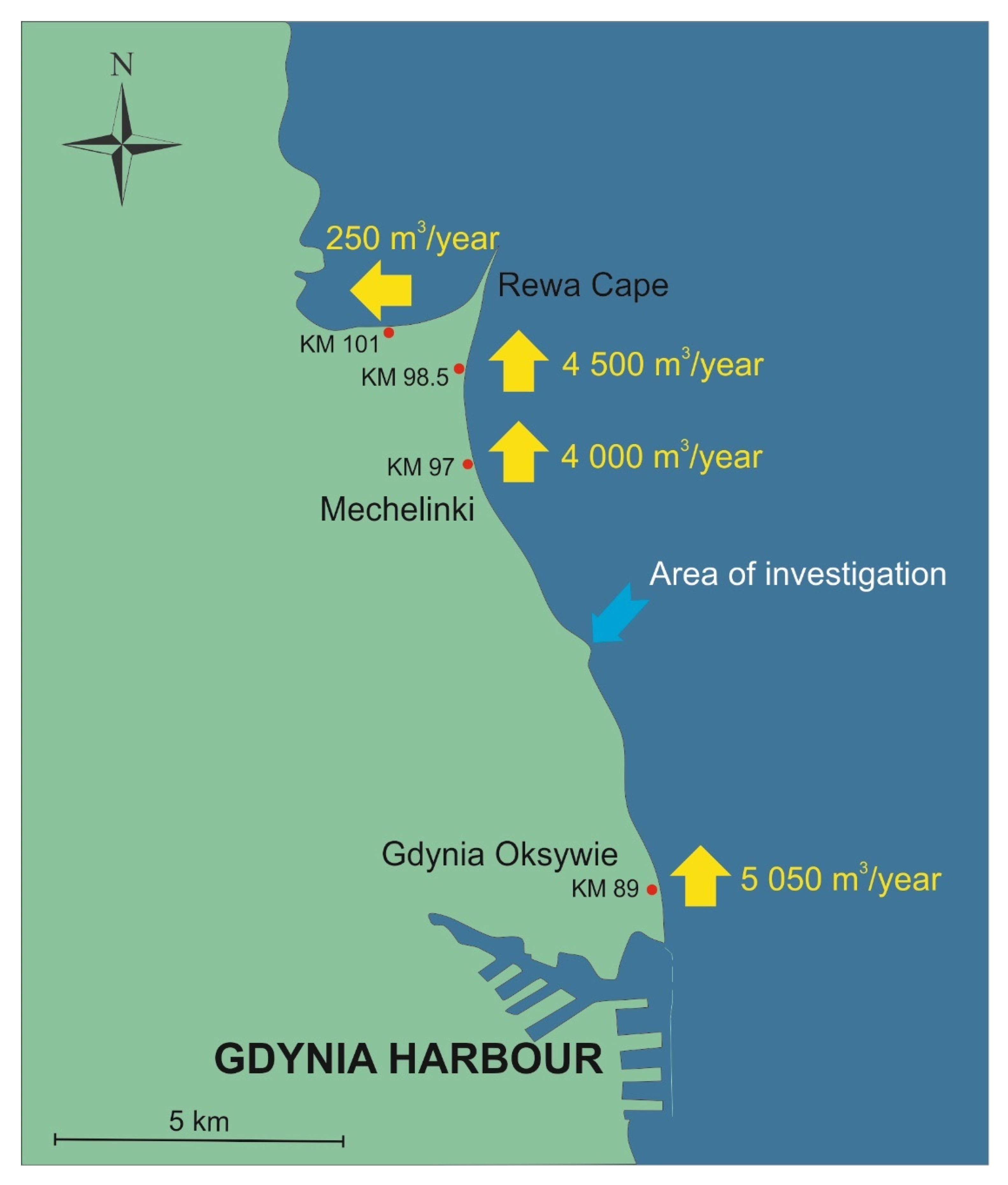
In order to quantitatively assess the rates of longshore sediment transport along the stretch of shore between KM 83.6 and KM 102.5, the authors of [
10] calculated the volume of sediment transport in four representative bathymetric profiles located at KM 101.0 (western side of the Rewa Cape), KM 98.5 (eastern side of the Rewa Cape), KM 97.0 (near the village of Mechelinki) and KM 89.0 (near the district of Oksywie), in an average statistical year. Calculations of sediment transport rates were performed for all onshore wind directions, i.e., N, NE, E and SE directions. Calculated rates of longshore sediment transport are, on average, 5000 m
3/year, with transport moving towards the north (
Figure 6).
3. Results
3.1. Analysis of Shoreline Development in a Historical Perspective
The available historical maps show a small protrusion within the analysed section of the seashore in the early 20th century. The shape and location of this protrusion can indicate that the site may have been the estuary section of a former river, which, as a result of fluvial processes, gave rise to a small delta (
Figure 7), a feature still visible on the map from 1940 (
Figure 8).
However, while Prussian maps from the 19th century and early 20th century can provide valuable reference material for large-scale geomorphological processes, drawing conclusions about a shoreline development along a stretch of several metres may be subject to error. Based on historical cartographic materials, it can be stated with certainty that the large-scale shoreline protrusion observed in this area since the 1960s was not present here in the first half of the 20th century (
Figure 3 and
Figure 9).
The formation of this large-scale protrusion is most likely directly related to a torpedo station built here from 1940–1942, and then destroyed after WWII (
Figure 10 and
Figure 11). The building was connected with the shore by a wooden pier. The pier was destroyed as a result of warfare and miscellaneous post-war activities. The structure has the same effects on the seashore as those observed in the vicinity of groynes, i.e., the shore accretion on the upstream side and erosion on the downstream side. Due to the predominant direction of the sediment transport (
Figure 6), accretion occurred on the southern side of the timber palisade, while erosion occurred on the northern side.
3.2. Shore Protection in Close Proximity to KM 93.6–93.9
Erosion processes occur in most of the cliffed sections of the southern Baltic coastline. Taking into account additional reinforcement of erosion processes resulting from the presence of WWII construction remnants at this location, considerable coastal erosion was to be expected at KM 93.6–93.9. In view of the coastal erosion hazard, usually, the only solution (in addition to beach nourishment) is to build revetments along the cliffed sections of the coast. Revetments have been erected at the foot of cliffs since long before the method of beach nourishment with sand sediment became popular (in Poland, beach nourishment was first used on a larger scale in the 1980s). However, a revetment usually leads to a permanent disappearance of the beach.
The first structures erected in this region to protect the cliff in Oksywie against erosion were built in 1905. Those were wooden groynes and a 600 m long revetment made of stone and concrete. They were situated on the easternmost protuberant section of the shore, starting from the naval port. In 1955, due to intensified erosion processes, the revetment was rebuilt and extended to approximately 1300 m. The revetment was located between KM 89.07 and KM 90.36. Further modifications were made in 1973, which consisted of the construction of a sheet pile wall with a reinforced concrete cap with riprap on the seaward side. From 2014–2015, the KM 89.00–90.70 section was protected with a mixed construction consisting of a stone embankment and reinforced concrete retaining wall, separating the embankment from a transportation route and minimising wave reflection and wave run-up. Basic information on the development of the protection system in this area is presented in
Table 1.
3.3. Shore Protection along KM 93.6–93.9
Pursuant to the Act of 25 September 2015 amending the Act on establishing the long-term Coastal Protection Programme (“Program ochrony brzegów morskich”; Dz.U. of 23 October 2015, item 1700), the shore stretch from Oksywie to Mechelinki (KM 89.1–96.6) is protected by beach nourishment and hard coastal protection structures. The functioning of revetments along this section—including the rubble revetment within the shore stretch of KM 93.6–93.9—is therefore in compliance with the recommendations of the aforementioned Act. However, none of the documents of the shoreline development records held by IBW PAN (Institute of Hydro-Engineering of Polish Academy of Sciences, Gdańsk, Poland) contains information on the described revetment. Furthermore, according to the materials available at IBW PAN, the theoretical shoreline defined according to the Coastal Protection Programme, runs in the landward part of the top of a local small coastal cliff (
Figure 12). This would mean that the rubble revetment in question is not included in the register of the shore protection structures kept by the Maritime Office in Gdynia.
For a very long time, until 2018, the coastal cliff in this area and its hinterland belonged to a large closed military area (which included, i.a., the navy airfield). It is very likely that the structure was erected by the army on a tight budget, without any prior analysis of local conditions or a technical design, and without the consent of relevant civil authorities of the public administration, including the Maritime Office. This type of situation mainly took place in the 1980s, when, due to a lack of sufficient financial resources, such solutions were used to temporarily protect the shore against erosion. In subsequent years, these structures were removed or modernised by the Maritime Office in Gdynia. The authors of this study are not aware of any such structures (apart from the analysed stretch of shore) to be currently found on the coast under the jurisdiction of the Maritime Office in Gdynia.
Regardless of the genesis of the structure in question and its low aesthetic value, the intuitive premises that led to its construction were legitimate. Furthermore, its sloping riprap construction—in contrast to vertical revetments—facilitates the sea wave energy dissipation and reflects waves to a small extent only, which does not result in the formation of a standing wave or intense scouring of sand in the foreground of the structure.
As already mentioned above, the analysed area is characterised by longshore sediment transport with a long-term direction from south to north. This results in extensive erosion processes along KM 93.6–93.9, and, therefore, the need for anti-erosion protection of the shore is indisputable. In this context, the revetment is highly effective in preventing coastal erosion.
The removal of the revetment, e.g., for aesthetic reasons, will result in coastal abrasion at this location, posing a threat to the safety of buildings situated in the immediate vicinity. The approximate range of potential coastline regression and the range of building development and functional urban areas with a pavement are shown in
Figure 13.
4. Discussion
The interest in the rubble concrete revetment from the media and representatives of social movements, focuses on the aesthetics of the structure and the environmental and landscape values of the seashore. Indeed, it is not a construction up to the standards of our times and modern technical possibilities, even more so as this stretch of shore is becoming increasingly popular, and the proximity of the transport hub further increases the number of people visiting the place. As the foreshore of the revetment is not a pedestrian walkway, the technical condition of the structure does not guarantee the safety of people walking across the revetment in storm surge conditions.
On the other hand, however, taking into account the function performed and the effectiveness of seashore protection to date, it is not recommended to disassemble the structure until an alternative structure is designed, e.g., similar to the nearby reinforcement of the shore at KM 92.62–92.95 in the form of a rock–palisade–gabion revetment. It is advisable to preserve the existing protection of the shore in the near future, and possible measures aimed at the modernisation of the protection system should be postponed until plans to build a marina in the area become final. The issue of shore protection should be integrated with the planned marina.
5. Conclusions
Based on the theoretical analysis of the local hydro- and litho-dynamic conditions and the impact of the revetment at KM 93.6–93.9, the following should be stated:
According to current legal standards, the seashore section at KM 93.6–93.9 is protected by beach nourishment and hard coastal protection structures, and the required level of shore protection is up to 20 years. This requirement is accommodated by the existing rubble concrete revetment. The functioning of the revetment is therefore in line with the recommendations of the respective legislation;
The predominant long-term direction of longshore sediment transport in the analysed area is from south to north and has a rate of 4000–5000 m3/year. Shore regression observed around the revetment is caused by so-called downstream erosion (behind the headland with remains of rock palisade structures);
Removal of the revetment will result in coastal abrasion at this location, posing a threat to the safety of buildings and functional urban areas in the immediate vicinity;
It is advisable to maintain the existing state of the shore. The revetment should not be disassembled until the concept of erecting a new structure or modernising the existing one is developed;
This issue of shore protection and reinforcement should be considered together with the issue of the marina planned for this area;
To provide protection for tourist traffic, it is suggested that information and warning signs are placed on the northern and southern sides of the revetment, recommending extreme caution near the structure and prohibiting walking on it during storm surge conditions.
Author Contributions
Conceptualisation, P.S. and R.O.; Formal analysis, P.S.; Investigation, R.O.; Methodology, P.S.; Resources, P.S.; Supervision, G.R.C.; Visualisation, P.S.; Writing—original draft, P.S. and R.O.; Writing—review and editing, P.S., R.O. and G.R.C. All authors have read and agreed to the published version of the manuscript.
Funding
This research received no external funding.
Institutional Review Board Statement
Not applicable.
Informed Consent Statement
Not applicable.
Data Availability Statement
Data sharing not applicable.
Conflicts of Interest
The authors declare no conflict of interest.
References
- Coastal Engineering Research Center (US). Shore Protection Manual; US Army Coastal Engineering Research Center: Washington, DC, USA, 1984. [Google Scholar]
- U.S. Army Corps of Engineers. Coastal Engineering Manual; U.S. Army Corps of Engineers: Washington, DC, USA, 2002.
- Sarker, S.; Veremyev, A.; Boginski, V.; Singh, A. Critical nodes in river networks. Sci. Rep. 2019, 9, 11178. [Google Scholar] [CrossRef] [PubMed] [Green Version]
- Sarker, S. Understanding the complexity and dynamics of anastomosing river planform: A case study of Brahmaputra River in Bangladesh, 2021. In Proceedings of the AGU 2021 Fall Meeting, New Orleans, LA, USA, 13–17 December 2021. [Google Scholar] [CrossRef]
- Mielczarski, A.; Ostrowski, R. Rozpoznanie Wpływu Brzegowych Systemów Ochronnych Na Zmiany Brzegów Wydmowych; IBW PAN: Gdańsk, Poland, 1989; pp. 1–55. (In Polish) [Google Scholar]
- Khan, I.; Ahammad, M.; Sarker, S. A study on River Bank erosion of Jamuna River using GIS and remote sensing technology. Int. J. Eng. Dev. Res. 2014, 2, 3369–3371. [Google Scholar]
- Sarker, S. A short review on computational hydraulics in the context of water resources engineering. Open J. Model. Simul. 2022, 10, 1–31. [Google Scholar] [CrossRef]
- Bailard, J.A. An energetics total load sediment transport model for a plane sloping beach. J. Geophys. Res. 1981, 86, 10938–10954. [Google Scholar] [CrossRef]
- Bijker, E.W. Longshore transport computations. J. Waterw. Harb. Coast. Eng. Div. 1971, 97, 687–701. [Google Scholar] [CrossRef]
- Szmytkiewicz, P.; Marcinkowski, T.; Szmytkiewicz, M.; Skaja, M. Opracowanie Planów Sztucznego Zasilania Brzegu Morskiego Na Odcinku Gdynia—Mosty; Urząd Morski w Gdyni: Gdynia, Poland, 2020; pp. 1–119. (In Polish)
| Publisher’s Note: MDPI stays neutral with regard to jurisdictional claims in published maps and institutional affiliations. |
© 2022 by the authors. Licensee MDPI, Basel, Switzerland. This article is an open access article distributed under the terms and conditions of the Creative Commons Attribution (CC BY) license (https://creativecommons.org/licenses/by/4.0/).


