
Numerical Study of the Bond Strength Evolution of Corroded Reinforcement in Concrete in Pull-Out Tests

 , ,
, ,  and
and 
Abstract
:Featured Application
Abstract
1. Introduction
2. Model Presentation
2.1. Model Geometry
2.2. Corrosion Model
2.3. Material Model
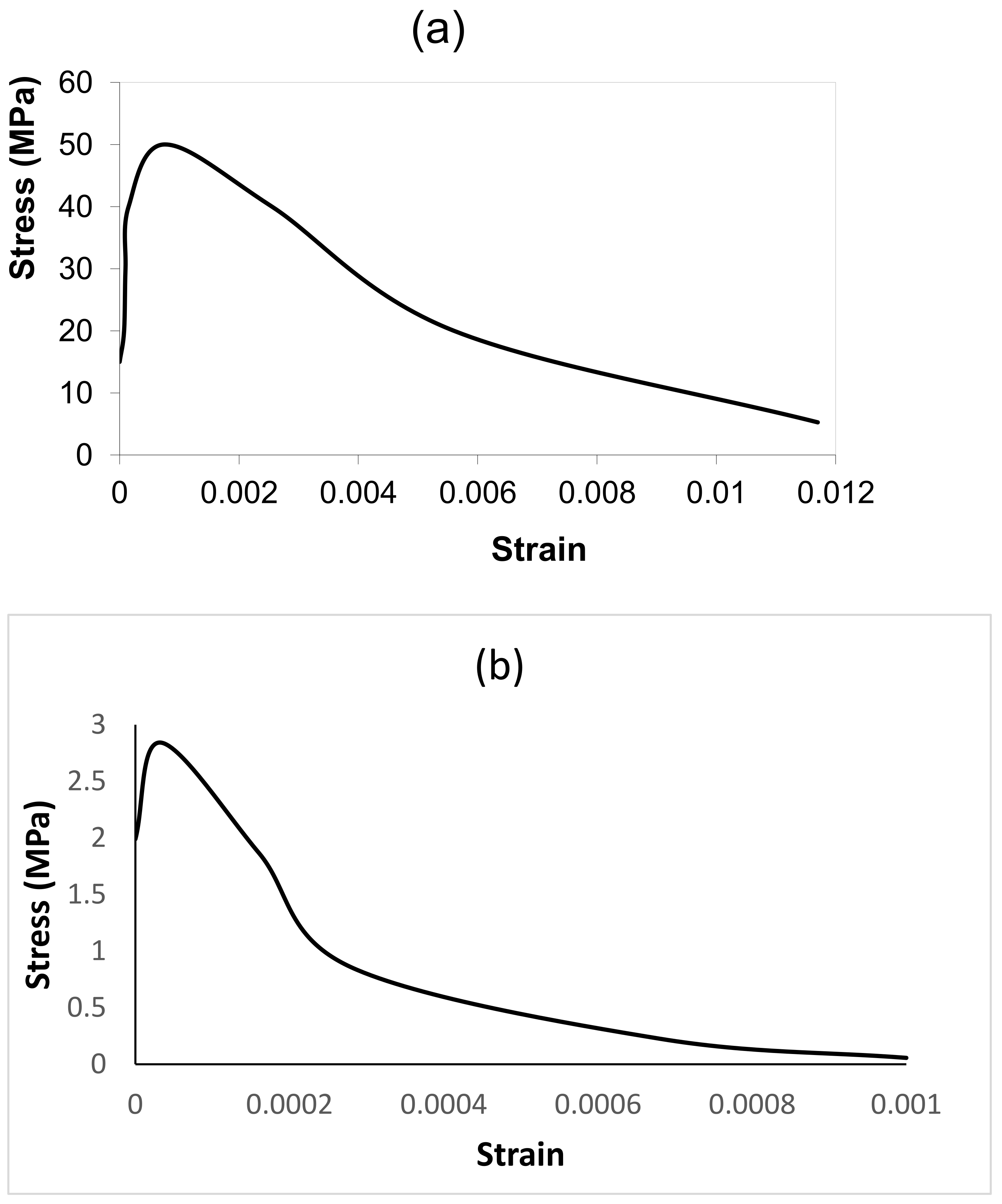
2.3.1. Concrete
2.3.2. Reinforcement
2.4. Boundary Conditions
2.4.1. Concrete Boundary Conditions
2.4.2. Rebar Boundary Conditions
2.4.3. Concrete-Rebar Interface
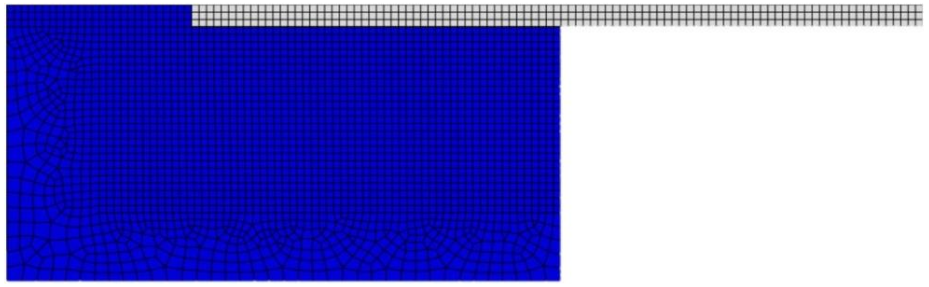
2.5. Mesh
3. Model Validation
4. Parametric Study
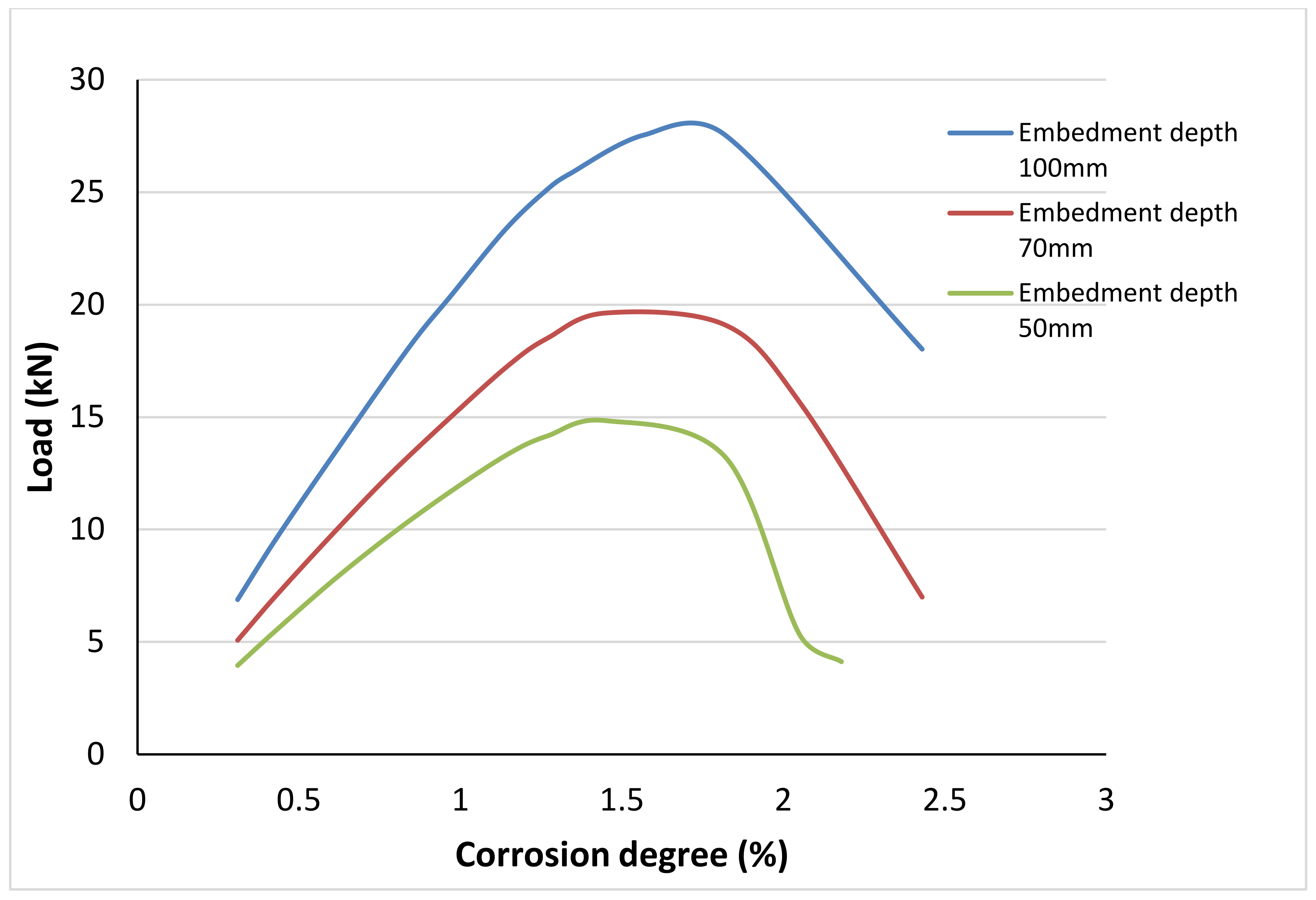
4.1. Effect of the Embedment Depth
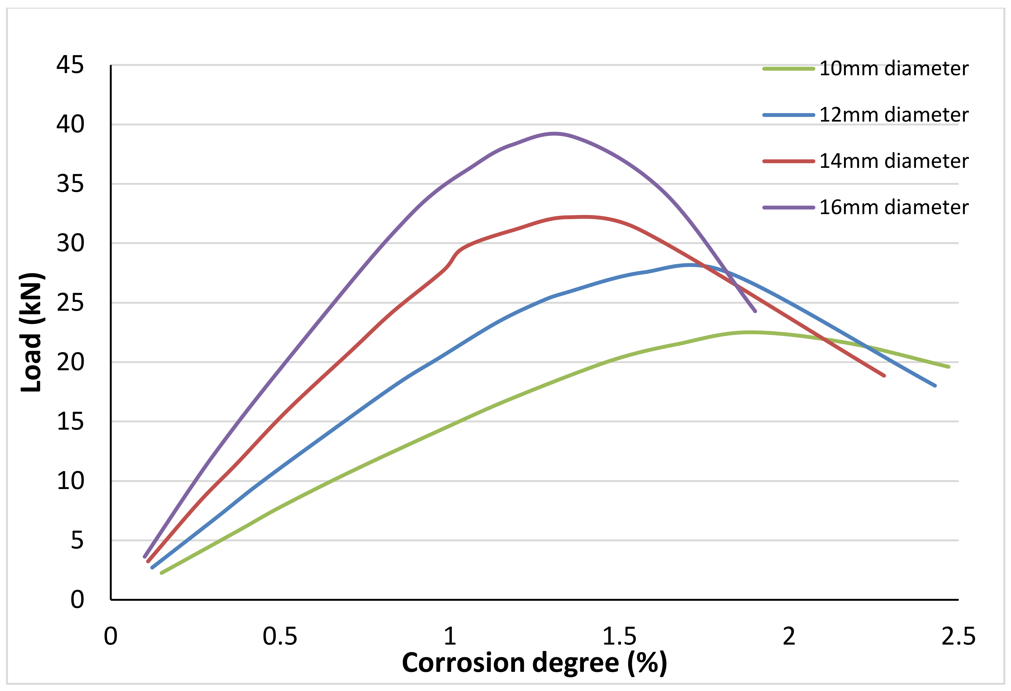
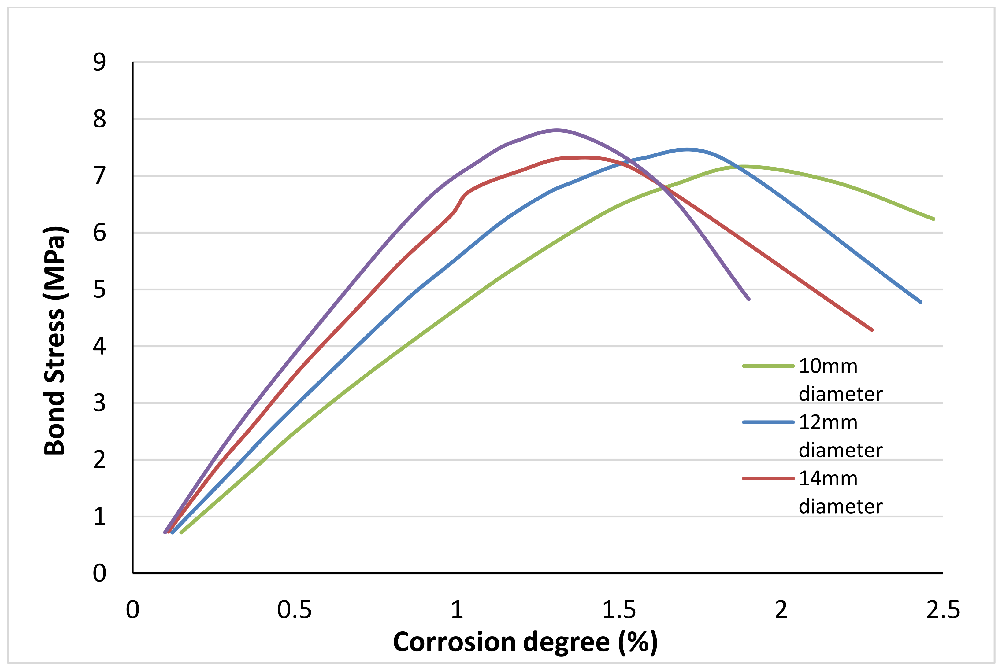
4.2. Effect of the Diameter of the Rebar
4.3. Effect of the Concrete Cover
5. Conclusions
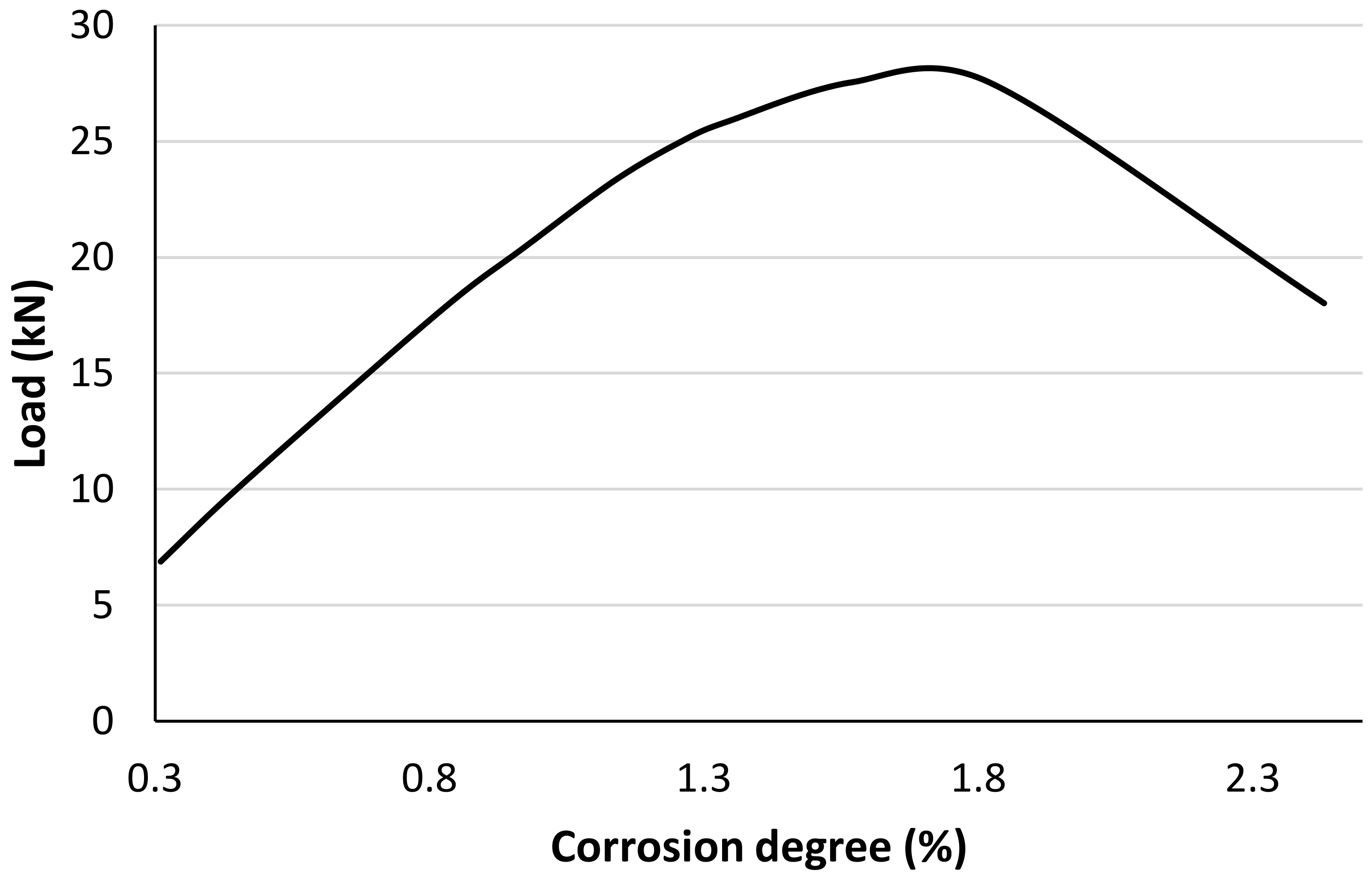
- At lower degrees of corrosion, approximately 1.5% in our model, the bond stress increases because the concrete at the interface is not yet sufficiently damaged;
- After a certain degree of corrosion, the bond stress significantly drops due to the damaging and deterioration of the concrete cover;
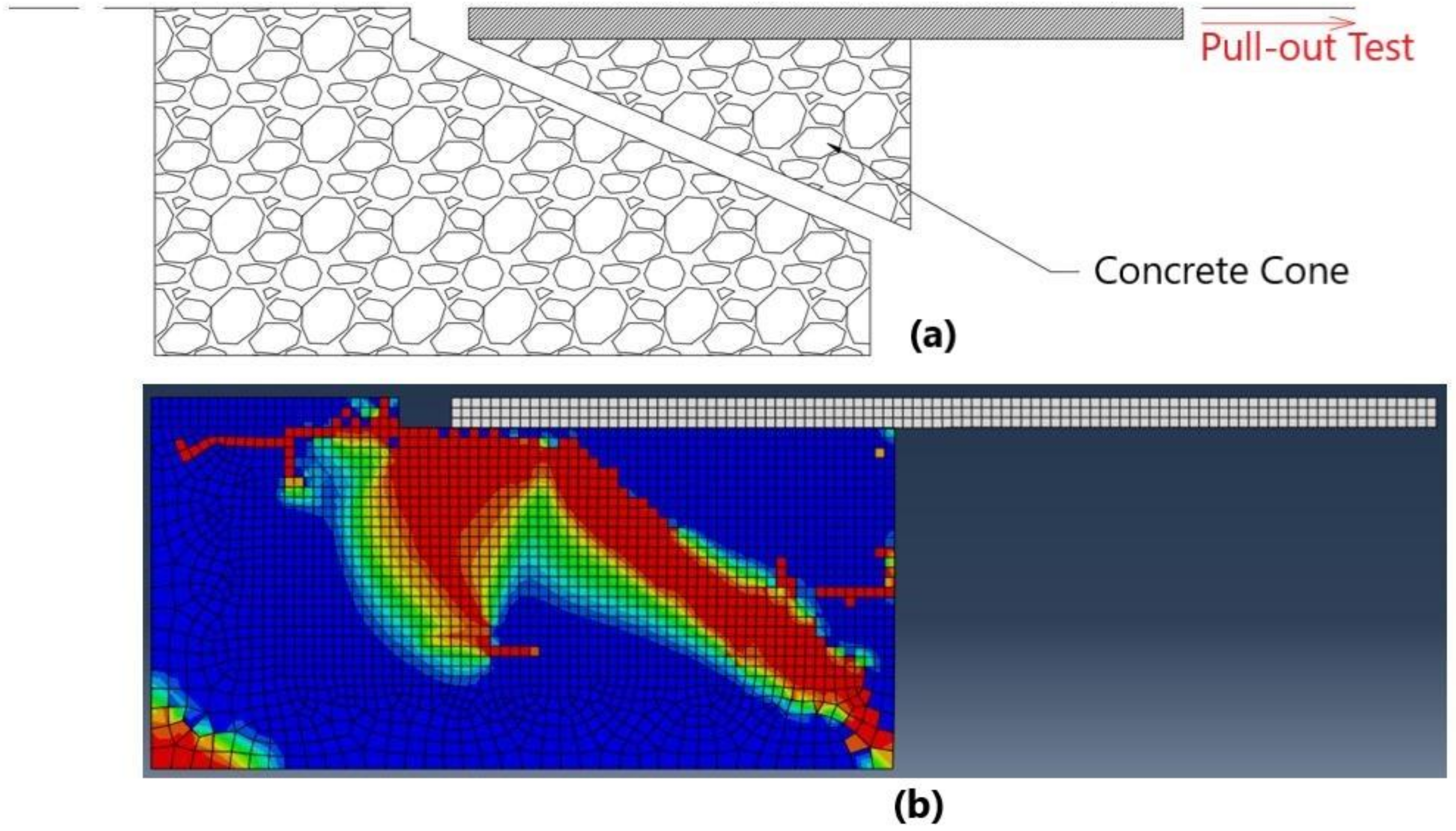
- Failure by splitting of concrete happens more often in our numerical model when the corrosion degree is greater than 1%;
- Increasing the embedment depth of the rebar increases the maximum pull-out load of each simulation for the same corrosion degree;
- Increasing the rebar diameter increases the bond stress and the maximum pull-out load for the same corrosion degree;
- The larger the rebar diameter is, the sooner the bond stress is affected and the concrete at the interface is damaged;
- Increasing the size of the concrete cover delays significantly the drop of the bond stress and the deterioration of the concrete cover.
Author Contributions
Funding
Institutional Review Board Statement
Informed Consent Statement
Data Availability Statement
Acknowledgments
Conflicts of Interest
References
- Fang, C.; Lundgren, K.; Chen, L.; Zhu, C. Corrosion influence on bond in reinforced concrete. Cem. Concr. Res. 2004, 34, 2159–2167. [Google Scholar] [CrossRef]
- Lee, H.S.; Noguchi, T.; Tomosawa, F. Evaluation of the bond properties between concrete and reinforcement as a function of the degree of reinforcement corrosion. Cem. Concr. Res. 2002, 32, 1313–1318. [Google Scholar] [CrossRef]
- Al-Sulaimani, G.; Kaleemullah, M.; Rasheeduzzafa, I.B. Influence of corrosion and cracking on bond behaviour and strength of reinforced concrete members. ACI Struct 1990, 87, 220–231. [Google Scholar]
- Almusallam, A.A.; Al-Gahtani, A.S.; Aziz, A.R. Rasheeduzzafar, Effect of reinforcement corrosion on bond strength. Constr. Build. Mater. 1996, 10, 123–129. [Google Scholar] [CrossRef]
- Chung, L.; Cho, S.H.; Kim, J.H.J.; Yi, S.T. Correction factor suggestion for ACI development length provisions based on flexural testing of RC slabs with various levels of corroded reinforcing bars. Eng. Struct. 2004, 26, 1013–1026. [Google Scholar] [CrossRef]
- Coccia, S.; Imperatore, S.; Rinaldi, Z. Influence of corrosion on the bond strength of steel rebars in concrete. Mater. Struct. Mater. Et Constr. 2016, 49, 537–551. [Google Scholar] [CrossRef]
- Cabrera, J.G. Deterioration of concrete due to reinforcement steel corrosion. Cem. Concr. Compos. 1996, 18, 47–59. [Google Scholar] [CrossRef]
- Zhu, W.; Dai, J.G.; Poon, C.S. Prediction of the bond strength between non-uniformly corroded steel reinforcement and deteriorated concrete. Constr. Build. Mater. 2018, 187, 1267–1276. [Google Scholar] [CrossRef]
- Lin, H.; Zhao, Y.; Yang, J.Q.; Feng, P.; Ozbolt, J.; Ye, H. Effects of the corrosion of main bar and stirrups on the bond behavior of reinforcing steel bar. Constr. Build. Mater. 2019, 225, 13–28. [Google Scholar] [CrossRef]
- Ozbolt, J.; Orsanic, F.; Balabanic, G. Modeling pull-out resistance of corroded reinforcement in concrete: Coupled three-dimensional finite element model. Cem. Concr. Compos. 2014, 46, 41–55. [Google Scholar] [CrossRef]
- Amleh, L.; Ghosh, A. Modeling the effect of corrosion on bond strength at the steel–concrete interface with finite-element analysis. Can. J. Civ. Eng. 2006, 33, 673–682. [Google Scholar] [CrossRef]
- Thybo, A.E.A.; Michel, A.; Stang, H. Smeared crack modelling approach for corrosion-induced concrete damage. Mater. Struc Tures Mater. Et Constr. 2017, 50, 146. [Google Scholar] [CrossRef] [Green Version]
- Bhargava, K.; Ghosh, A.K.; Mori, Y.; Ramanujam, S. Model for cover cracking due to rebar corrosion in RC structures. Eng. Struct. 2006, 28, 1093–1109. [Google Scholar] [CrossRef]
- Bhargava, K.; Ghosh, A.K.; Mori, Y.; Ramanujam, S. Corrosion-induced bond strength degradation in reinforced concrete-Analytical and empirical models. Nucl. Eng. Des. 2007, 237, 1140–1157. [Google Scholar] [CrossRef]
- Wang, X.; Liu, X. Modeling bond strength of corroded reinforcement without stirrups. Cem. Concr. Res. 2004, 34, 1331–1339. [Google Scholar] [CrossRef]
- Jin, W.-I. Effect of Corrosion on Bond Behavior and Bending Strength of Reinforced Concrete Beams. J. Zhejiang Univ. SCIENCE 2001, 2, 298. [Google Scholar] [CrossRef]
- ABAQUS. ABAQUS Documentation; Dassault Systems: Providence, RI, USA, 2011. [Google Scholar]
- Jankowiak, T.; Łodygowski, T. Identification of parameters of concrete damage plasticity constitutive model. Found. Civ. Environ. Eng. 2014, 6, 53–69. [Google Scholar]
- Delhomme, F.; Brun, M. Pullout simulation of post installed chemically bonded anchors in UHPFRC. In Proceedings of the MATEC Web of Conferences, Cape Town, South Africa, 19–21 November 2018; Volume 199. [Google Scholar]
- Andrade, C.; Alonso, C.; Molina, F.J. Cover cracking as a function of bar corrosion: Part I-Experimental test. Mater. Struct. 1993, 26, 453–464. [Google Scholar] [CrossRef]
- Lundgren, K. Bond between ribbed bars and concrete. Part 2: The effect of corrosion. Mag. Concr. Res. 2005, 57, 383–395. [Google Scholar] [CrossRef] [Green Version]
- Laursen, T.A. Computational Contact and Impact Mechanics. Meccanica 2003, 38, 393–394. [Google Scholar] [CrossRef]
- Raous, M.; Karray, M.A. Model coupling friction and adhesion for steel concrete interfaces. Int. J. Comput. Appl. Technol. 2009, 34, 42. [Google Scholar] [CrossRef]
- Lin, H.; Zhao, Y.; Feng, P.; Ye, H.; Ozbolt, J.; Jiang, C.; Yang, J.Q. State-of-the-art review on the bond properties of corroded reinforcing steel bar. Constr. Build. Mater. 2019, 213, 216–233. [Google Scholar] [CrossRef]
- Tondolo, F. Bond behaviour with reinforcement corrosion. Constr. Build. Mater. 2015, 93, 926–932. [Google Scholar] [CrossRef]
- Horrigmoe, G.; Saether, I.; Antonsen, R.; Arntsen, B. Laboratory Investigations of Steel Bar Corrosion in Concrete, Sustainable Bridges: Sixth Framework Programme SB 3.10. Available online: http://www.diva-portal.se/smash/get/diva2:1337406/FULLTEXT01.pdf (accessed on 10 January 2021).
- Lundgren, K.; Kettil, P.; Hanjari, K.Z.; Schlune, H.; Roman, A.S.S. Analytical model for the bond-slip behaviour of corroded ribbed reinforcement. Struct. Infrastruct. Eng. 2012, 8, 157–169. [Google Scholar] [CrossRef]
- Gambarova, P.G.; Rosati, G. Bond and splitting in reinforced concrete: Test results on bar pull-out. Mater. Struct. 1996, 29, 267–276. [Google Scholar] [CrossRef]


| E(GPa) | ν | ψ (◦) | ϵ | σb0/σc0 | Kc |
|---|---|---|---|---|---|
| 19.7 | 0.19 | 38 | 1 | 1.12 | 0.666 |
| E (GPa) | ν |
|---|---|
| 210 | 0.2 |
Publisher’s Note: MDPI stays neutral with regard to jurisdictional claims in published maps and institutional affiliations. |
© 2022 by the authors. Licensee MDPI, Basel, Switzerland. This article is an open access article distributed under the terms and conditions of the Creative Commons Attribution (CC BY) license (https://creativecommons.org/licenses/by/4.0/).
Share and Cite
El Alami, E.; Fekak, F.-E.; Garibaldi, L.; Moustabchir, H.; Elkhalfi, A.; Scutaru, M.L.; Vlase, S. Numerical Study of the Bond Strength Evolution of Corroded Reinforcement in Concrete in Pull-Out Tests. Appl. Sci. 2022, 12, 654. https://doi.org/10.3390/app12020654
El Alami E, Fekak F-E, Garibaldi L, Moustabchir H, Elkhalfi A, Scutaru ML, Vlase S. Numerical Study of the Bond Strength Evolution of Corroded Reinforcement in Concrete in Pull-Out Tests. Applied Sciences. 2022; 12(2):654. https://doi.org/10.3390/app12020654
Chicago/Turabian StyleEl Alami, Eliass, Fatima-Ezzahra Fekak, Luigi Garibaldi, Hassane Moustabchir, Ahmed Elkhalfi, Maria Luminita Scutaru, and Sorin Vlase. 2022. "Numerical Study of the Bond Strength Evolution of Corroded Reinforcement in Concrete in Pull-Out Tests" Applied Sciences 12, no. 2: 654. https://doi.org/10.3390/app12020654
APA StyleEl Alami, E., Fekak, F.-E., Garibaldi, L., Moustabchir, H., Elkhalfi, A., Scutaru, M. L., & Vlase, S. (2022). Numerical Study of the Bond Strength Evolution of Corroded Reinforcement in Concrete in Pull-Out Tests. Applied Sciences, 12(2), 654. https://doi.org/10.3390/app12020654