Article

Upgraded Combined Inject-and-Transfer System for Serial Femtosecond Crystallography

1
Department of Mechanical Engineering, Pohang University of Science and Technology, Pohang 37673, Korea
2
Pohang Accelerator Laboratory, Pohang University of Science and Technology, Pohang 37673, Korea
3
Department of Chemical Engineering, Pohang University of Science and Technology, Pohang 37673, Korea
4
Department of Materials Science and Engineering, Pohang University of Science and Technology, Pohang 37673, Korea
5
Department of Life Science, Pohang University of Science and Technology, Pohang 37673, Korea
6
POSTECH Biotech Center, Pohang University of Science and Technology, Pohang 37673, Korea
*
Authors to whom correspondence should be addressed.
Appl. Sci. 2022, 12(18), 9125; https://doi.org/10.3390/app12189125
Submission received: 10 August 2022 / Revised: 7 September 2022 / Accepted: 9 September 2022 / Published: 11 September 2022
(This article belongs to the Section Optics and Lasers)

Abstract

:

Featured Application

Recently upgraded inject-and-transfer system will improve beamtime efficiency for serial femtosecond crystallography.

Abstract

Serial femtosecond crystallography (SFX) using an X-ray free-electron laser (XFEL) can be applied to determine the room-temperature structure of target molecules while minimizing radiation damage and visualizing molecular dynamics. In SFX, a sample delivery system is required to deliver microcrystals to the XFEL beam path in a serial manner. We recently developed a sample delivery method, the combined inject-and-transfer system (BITS), which is a hybrid method based on the injector and fixed-target scanning approach. In this study, we introduced recently upgraded hardware to move the injection needle in the direction of the XYZ-axis and a graphic user interface for user motion control. Furthermore, we report that the viscous solution containing 10% (w/v) PEG 3350 or PEG 6000 that is widely used for protein crystallization can be stably deposited on polyimide film with a hydrophobic surface without any special treatment. Moreover, the development of an inject-and-diffuse method for time-resolved studies with liquid applications in the BITS and its preliminary results are reported. This study provides up-to-date instrument information to SFX users using BITS and provides insights to instrument developers for SFX.

1. Introduction

The traditional macromolecular crystallography (MX) technique enables the determination of crystal structure at atomic resolution [1,2]. MX helps in elucidating the molecular mechanism of macromolecules, provides insight into drug design, and enables rational engineering of industrially applicable enzymes [3,4,5]. However, traditional MX has experimental limitations, such as the occurrence of radiation damage and the necessity for cryogenic environments, and it is limited to static structural information [6]. These technical limitations can be overcome with serial crystallography (SX) using X-ray free-electron lasers (XFEL) or synchrotron X-rays [7]. The SX technique enables the determination of room-temperature structures with minimal radiation damage, which provides more accurate data on the structural fluctuations of target molecules [8,9,10]. Moreover, time-resolved molecular dynamics can be observed via pump-probe or mix-and-injection experiments [11,12,13].
In an SFX experiment, the crystal sample is exposed to XFEL only once. To collect the complete dataset, numerous microcrystals are continuously delivered to the X-ray interaction point. To deliver a large number of microcrystals, various sample delivery methods, such as injectors [14,15,16], viscous media [17,18,19,20,21,22,23,24], fixed-target scanning [25,26,27,28,29,30,31], capillary methods [32,33], microfluidic devices [34,35,36,37], and hybrids, have been developed and applied in SX data collection.
The NCI experiment hutch at the Pohang Accelerator Laboratory X-ray Free-Electron Laser (PAL-XFEL) facility has two SFX sample chambers to deliver microcrystals to the X-ray interaction point: (1) a multifarious injection chamber for molecular structure study (MICOSS) [38] and (2) fixed-target SFX (FT-SFX) chambers. In the MICOSS system, particle solution delivery (PSD) [38], carrier matrix delivery (CMD) [38], and microliter volume (MLV) syringe injectors [39] have been applied to deliver microcrystals into the XFEL beam path in helium or air environments. This system allows for the collection of general XFEL diffraction data and pump-probe experiments using optical lasers. In the FT-SFX system, a fixed-target approach using a conventional 2D raster (with a nylon mesh sample holder or viscous medium-based crystal support) [28,30] or 1D scanning using polyimide tubing with a servo view system [31] can be performed.
Among these sample delivery methods, the fixed-target scanning system has the advantage of minimizing the consumption of crystal samples, as well as the physical damage to crystals, during sample delivery. When a fixed-target sample holder is exposed to an XFEL, bubbles are generated from the crystal suspension, indicating that radiation damage has occurred and radicals may be generated. Although it has not been experimentally proven how radiation damage due to initial XFEL exposure affects the samples, it is prudent to minimize radiation damage. From this perspective, the injector system has advantages as it continuously releases fresh samples from the injector. However, this system requires more effort to create a stable injection stream, and sample consumption is higher than with the FT-SFX system.
We recently developed a combined inject-and-transfer system (BITS) and successfully applied it to data collection [40]. Crystal suspensions or crystals embedded in a viscous medium are deposited on UV/ozone (UVO)-treated polyimide film using an injector needle and transferred to the X-ray interaction point in a programmed translation stage. As all crystal samples excluded from the injector are deposited on the UVO-treated polyimide film, establishing a stable injection stream is not essential, which allows for improved beamtime efficiency [40]. Typically, while the width of the general injection stream from the injector or syringe is much larger than the XFEL beam size, X-rays are only transmitted to one point of the injection stream, thereby wasting unexposed samples. In contrast, in BITS, the crystal sample deposited on the film is raster scanned by translation in the vertical and horizontal directions, depending on the desired scan interval length; thus, the sample consumption is dramatically reduced [40]. Therefore, the BITS system combines the advantages of fixed-target scanning and injector approaches. After developing the BITS system, we have been continuously upgrading its hardware, software, and scientific programs.
In this paper, we introduce the upgraded BITS system and demonstrate a new approach for sample deposition on a polyimide film without UV treatment and a preliminary experiment for the inject-and-diffuse method for time-resolved SFX applications. Our results may aid in improving the current status of SFX experiments using the BITS system and provide a basis for future developments.

2. Materials and Methods

2.1. Materials

All chemicals (glycerol, PEG 400, PEG 3350, and PEG 6000) were purchased from Sigma-Aldrich (St. Louis, MO, USA). The syringe (1000 μL) was purchased from BD Plastics Ltd. (Sunderland, UK). Polytetrafluoroethylene (PTFE) tubing was purchased from Precigenome LLC (San Jose, CA, USA). A blunt-type syringe needle (length, 100 mm; inner diameter, 150 mm) was purchased from Solution Korea (Osan, Korea). The polyimide film (50 μm) was purchased from Suzhou Kying Industrial Materials Co., Ltd. (Suzhou, China). N,N′,N″-triacetylchitotriose was purchased from Dextra (Reading, UK). Lysozyme from chicken egg whites (L6876) was purchased from Sigma-Aldrich. Lysozyme crystals were obtained using a batch crystallization method as previously reported [41]. The crystal size was approximately <10 × 10 × 10 μm3.

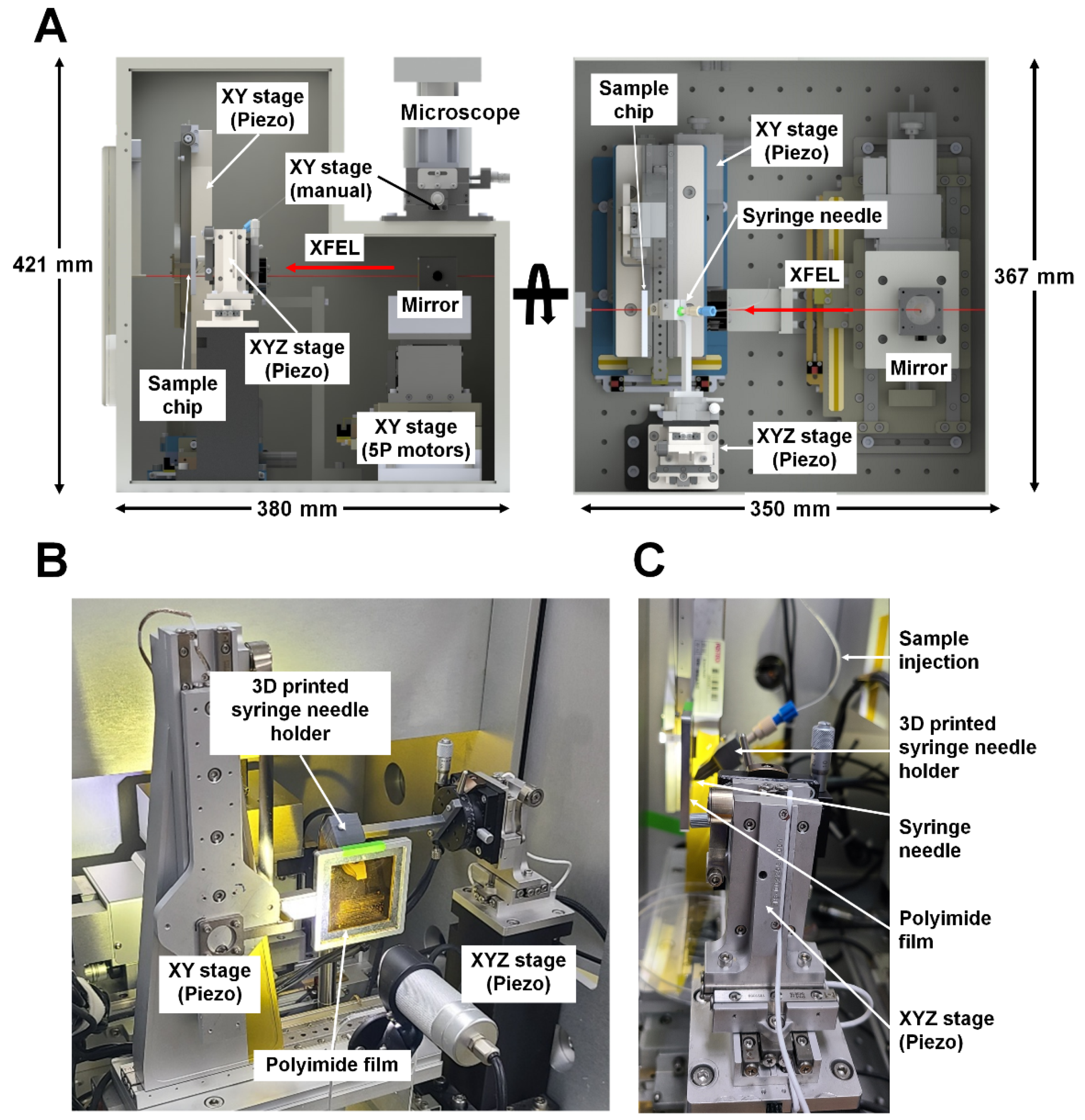
2.2. Upgrade of BITS Hardware

The translation stages for the sample holder and camera viewing system used in the BITS system were identical to those of a previously reported fixed-target sample chamber [31]. The sample mounter, which moves the film on which the crystals are seated, was upgraded to move in the vertical and horizontal directions using SLC-24180-W-D-SC (SmarAct, Oldenburg, Germany) linear piezo stages. An XYZ-axis motorized piezo stage consisting of three SLC-2445 (SmarAct) linear piezo stages was used for real-time contact between the syringe needle and sample film instead of the previously used manual stage.

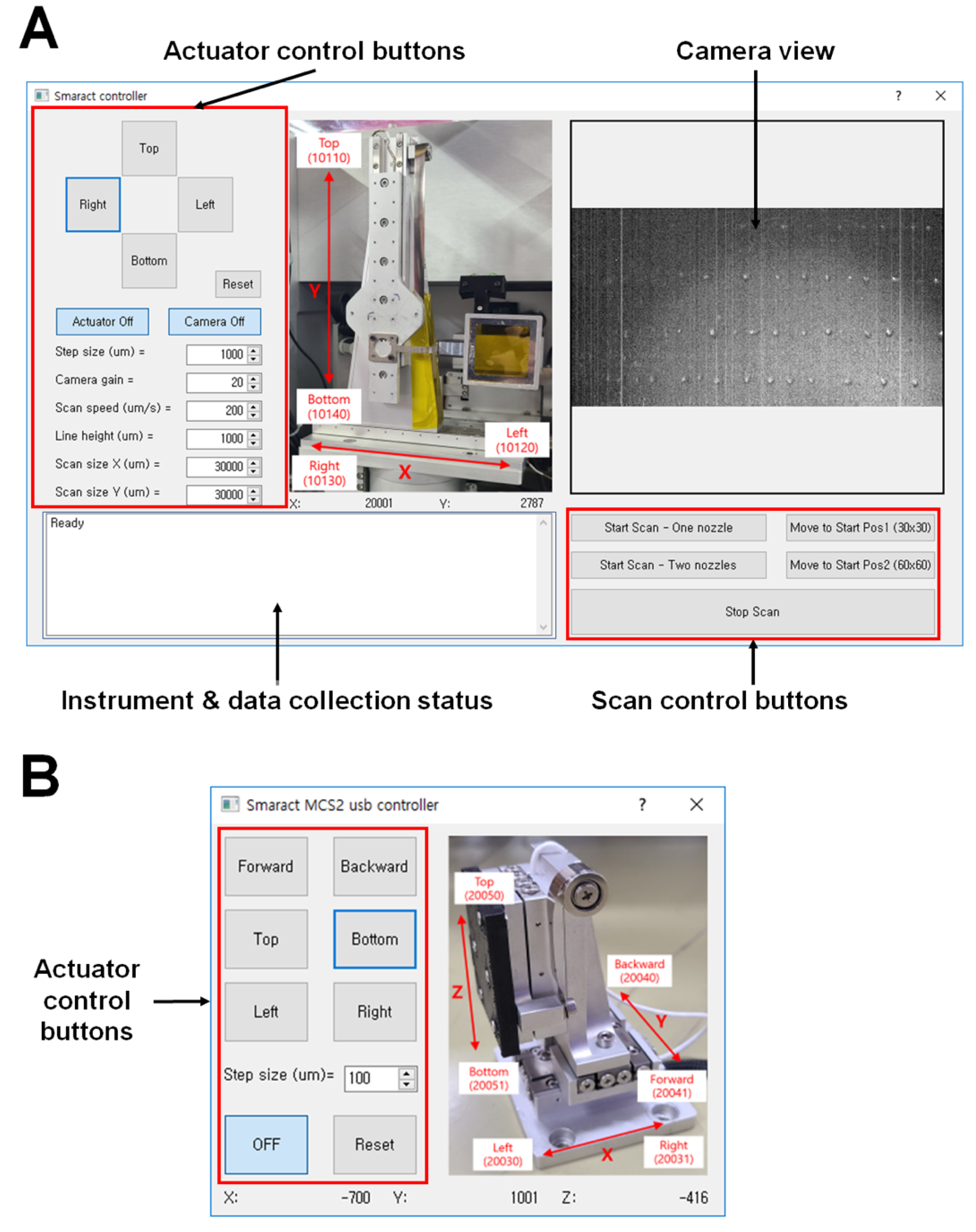
2.3. Motion Control Software

The control software for driving the BITS system was designed directly as a graphical user interface (GUI). Python GUI code information is shown in Supplementary Tables S1 and S2.

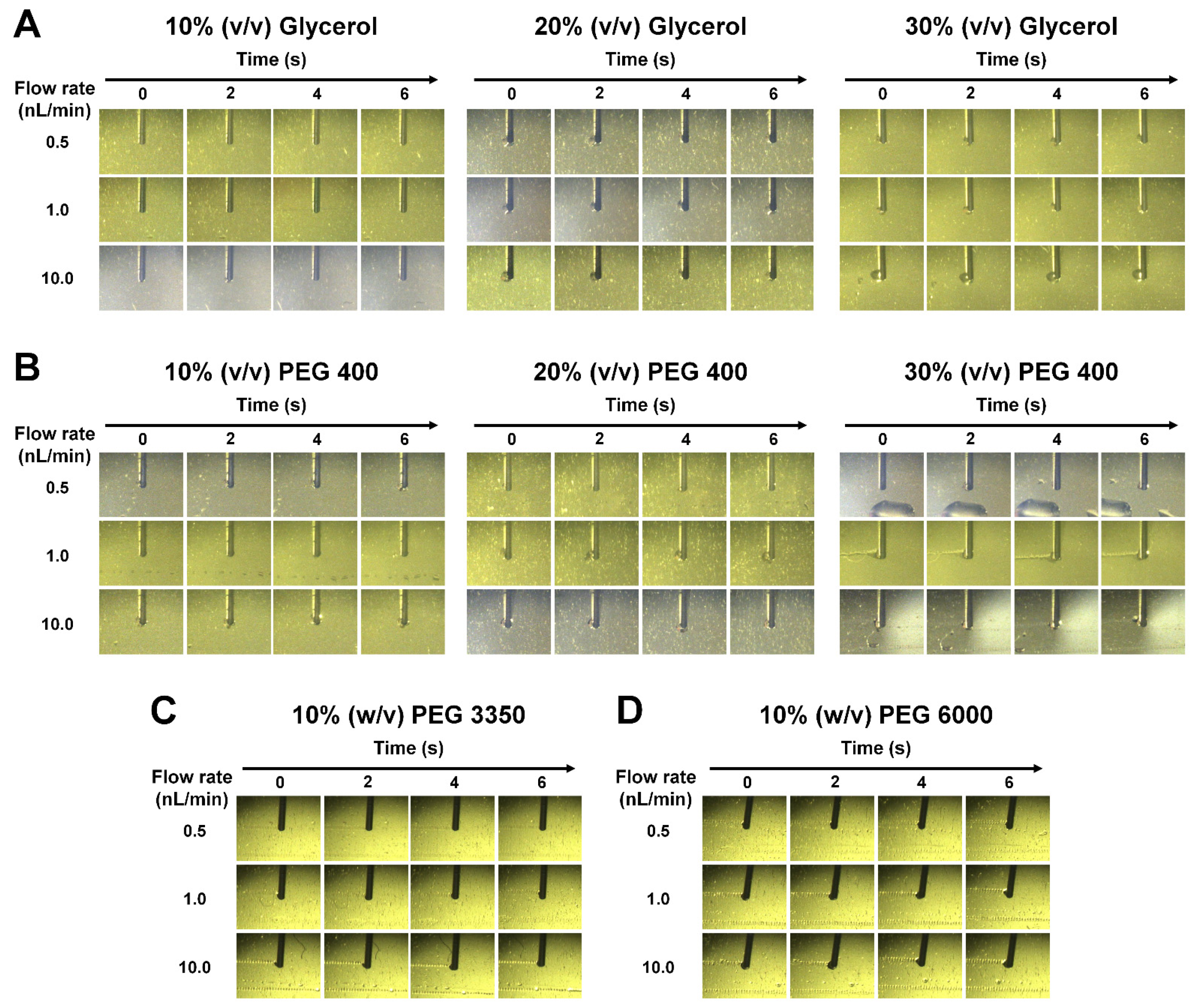
2.4. Injection Experiment

The viscous solutions (10–30% (v/v) glycerol, 10–30% (w/v) PEG 400, 10% (w/v) PEG 3350, and 10% (w/v) PEG 6000) were transferred to a 1 mL syringe. These solutions were injected onto a polyimide film at flow rates of 0.5, 1, and 10 nL/min using a syringe pump (Chemyx Inc., Houston, TX, USA). The translation stage was moved in the vertical and horizontal directions in the raster scan mode, with a translation speed of 1.5 mm/s in both vertical and horizontal directions.

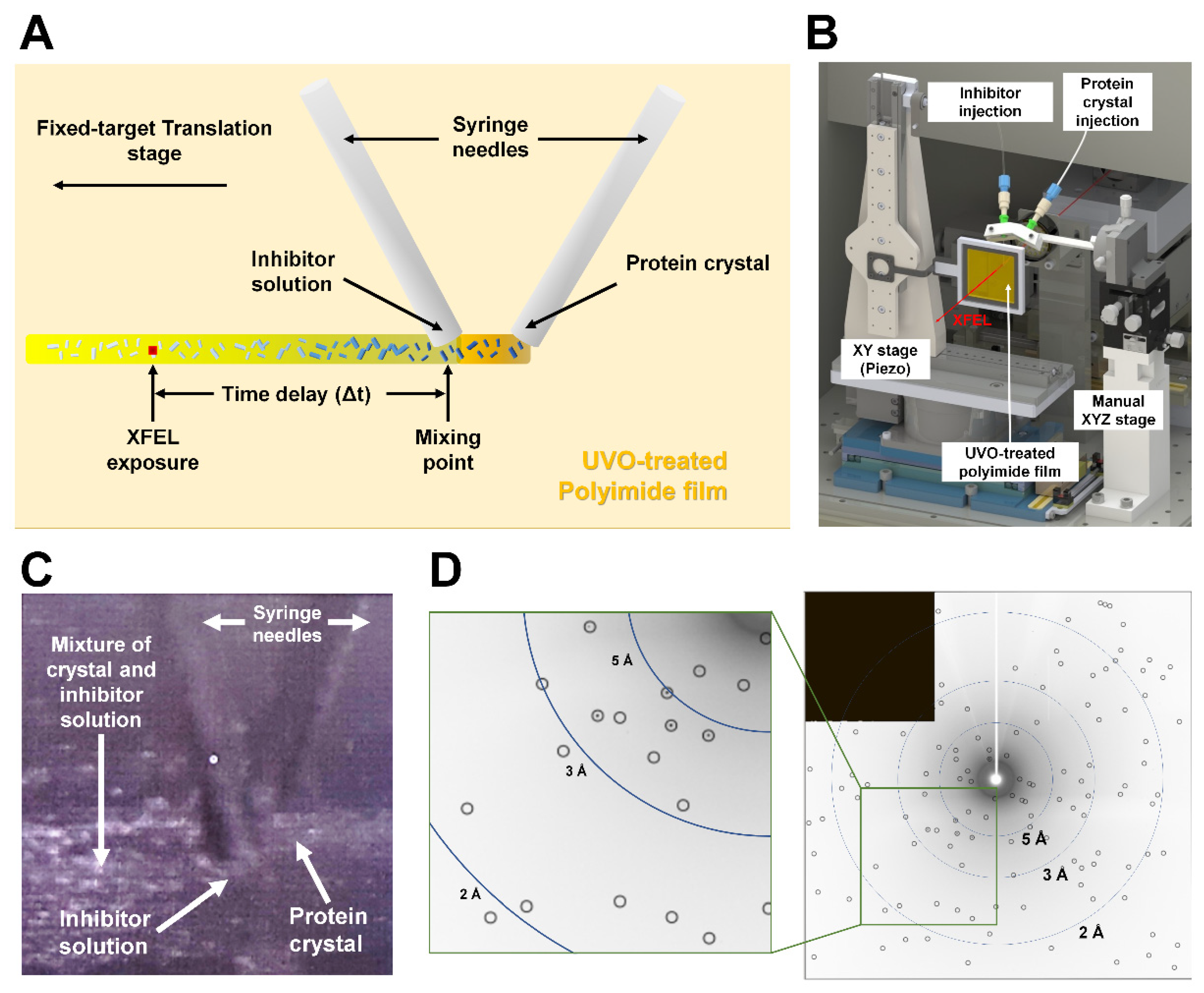
2.5. Preliminary Experiment for Inject-and-Diffuse Approach

XFEL data collection was performed using the NCI experiment hutch [42] at PAL-XFEL [43]. The XFEL beam was projected at 3 × 2 μm (vertical × horizontal; full width at half maximum) at the sample position by a Kirkpatrick–Baez mirror at 9.5 keV [44]. Lysozyme crystals were embedded into a viscous lard medium by mechanical mixing using a dual-syringe setup. The crystals embedded in the viscous medium and N,N′,N″-triacetylchitotriose solution were transferred to separate syringes. The syringe needle was aligned in contact with the polyimide film. Both samples were injected at a flow rate of 50 nL/min using a syringe pump. The UVO-treated polyimide film was moved horizontally at a rate of 1.5 mm/s. The XFEL interaction point and needle tip closest to the XFEL interaction point were 300 μm apart. The sample environment containing the injection and translation was exposed to the atmosphere. Diffraction data were recorded using an MX225-HS detector (Rayonix) at 25–27 °C. Diffraction images, including Bragg peaks, were filtered using Cheetah [45] and indexed using the CrystFEL program [46]. The filtered images were deposited in ZENODO (https://zenodo.org/record/6965404#.YyKD13ZBzIU, accessed on 5 August 2022).

3. Results and Discussion

3.1. Current Status of BITS Hardware

In the BITS system, two translation systems are required to align the injector and transfer the film holder to the X-rays [40]. In a previous study, the injector needle was mounted on a 3D printed needle holder, which was connected to a manual stage in the XYZ direction [40]. The film, where the crystal sample was deposited, was moved by a motorized piezo motor stage in the XY direction. As previously reported for BITS sample delivery, the needle tip and polyimide film are in contact, allowing the sample from the tip of the needle to be deposited directly on the film. When the needle tip and film are separated, the sample forms a drop at the needle tip, impairing data collection until it touches the film [40]. Therefore, for efficient data collection, it is important to ensure contact between the film and needle tip before the experiment and during data collection. Although the needle tip and film are precisely aligned before data collection, sometimes the needle tip and film detach during data collection. This occurs when the film on which the crystals are deposited is not perfectly flat or when the needle tip moves when it touches the film, at times changing the path owing to friction. In this case, because the system must wait until the sample is stably deposited on the film, the beamtime efficiency is lowered, and unnecessary sample consumption occurs.
To solve this problem, in the current upgrade, when the film and needle do not come into contact during data collection, one of them is moved along the Z-axis to make contact again. If the fixed-target scanning stage is moved along the Z-axis, it may deviate from the focal point of the focused XEFL, which affects crystal diffraction. In addition, data processing may be affected as the distance from the sample to the detector changes. In contrast, the Z-axis movement of the syringe needle does not affect the crystal position at the XFEL focal point or the distance between the crystals and detector. Accordingly, the manual injector stage was replaced by the XYZ-axis motorized piezo stage for real-time alignment between the syringe needle and polyimide (Figure 1A). Thus, if the needle does not come into contact with the film during data collection, it can contact the polyimide film by moving the Z-axis of the piezo stage to which the syringe needle is coupled. As the Z-axis travel length of the piezo stage was 29 mm, the tip of the syringe needle could also be moved 29 mm in the Z-axis direction. This travel length indicates that they can be aligned by moving the needle tip even if the 80 mm polyimide film is scanned horizontally, with the sample holder tilted by 20°. Taken together, the replacement of the manual injection stage with a motorized piezo stage reduces unnecessary sample consumption during data collection and allows for more efficient use of the beamtime.

3.2. Instrument Control

The control system of the PAL-XFEL facility is mainly an experimental physics and industrial control system (EPICS). To manipulate the motorized translation stages in BITS, a Python graphical user interface (GUI-based control system) was developed (Figure 2). The translation code was generated using C++ (see Supporting Information). The operator or researcher can intuitively and conveniently use the programs for the BITS system, which allow control of the fixed-target sample holder in the XY direction (Figure 2A) and needle position in the XYZ direction (Figure 2B). For the GUI program for fixed-target control, the upper-right panel of the GUI shows the camera view, which observes the sample being deposited from the injector needle and the sample moving on the film (Figure 2A). The upper-left panel is used for controls that can move in the XY direction in the stage to which the sample holder is connected (Figure 2A). The lower-left corner displays the log information regarding the data scan progress (Figure 2A). The lower right panel lists the types of fixed-target scan methods. Selecting the desired scan method begins data collection (Figure 2A). For the GUI program for needle position control, the buttons on the left panel are used to precisely control the position of the syringe needle in the XYZ direction (Figure 2B). The right panel shows the direction and travel length of the motion piezo stage for the XYZ direction (Figure 2B).

3.3. Sample Injection Expriment

In a previous study, we investigated the deposition of crystallization solution (100 mM Na-acetate, pH 4.5, 5% (w/v) PEG 8000, and 3.5 M NaCl) on polyimide films during inject-and-transfer development [40]. The crystallization solution was not deposited stably because of the hydrophobic properties of the polyimide film, which formed a drop of solution at the needle tip. To solve this problem, the hydrophilicity of the polyimide film surface was increased by UVO treatment. Then, the crystallization solution was stably deposited [40]. The surface of the polyimide film subjected to UVO treatment has a disadvantage in that the hydrophilicity decreases when exposed to air. Thus, avoiding long-term exposure to air after UVO treatment is critical. Accordingly, it is necessary to continuously replace the UVO-treated film after a certain period, which is inconvenient and lowers beamtime efficiency. To solve this problem, we considered the direct use of non-UVO-treated hydrophobic polyimide films by increasing the sample viscosity, which has the advantage of simplifying the experimental process for UVO treatment.
From the perspective of protein samples, typical crystal suspensions may exhibit low viscosity and hydrophilic properties. In contrast, crystallization solutions often contain highly viscous or hydrophobic substances. We expected that a crystallization solution containing a highly viscous substance would deposit well owing to the hydrophobic properties of polyimide film surfaces. Glycerol is used to reduce protein aggregation during purification and storage. In addition, glycerol is widely used as a cryoprotectant solution in traditional macromolecular crystallography experiments. Accordingly, we considered that there would be stable crystal samples even when glycerol was added to the crystal suspension. Polyethylene glycol (PEG)-based reagents are widely used as precipitants in protein crystallization and exhibit high viscosity at specific concentrations. Considering this, we investigated the deposition of glycerol and polyethylene glycol solutions on polyimide films. If a high concentration of glycerol or PEG is used, the viscous solution will deposit well on the polyimide film, but there may be physical damage to the crystals during long-term incubation. Accordingly, the concentrations of glycerol or PEG solution used in this experiment were ≤30%. All solutions were delivered onto the polyimide film through a syringe needle at flow rates of 0.5, 1, and 10 nL/min.
When 10% (v/v) glycerol and 10% (v/v) PEG 400 were injected, it was observed that a drop was formed at the injection needle tip without being deposited on the polyimide film (Figure 3A,B). This indicates that the injected glycerol and PEG 400 have low viscosity when interacting with the hydrophobic surface of the polyimide film. The concentrations of glycerol and PEG 400 were increased to 20% or 30% to increase viscosity. The 20% and 30% (v/v) glycerol solutions were not stably deposited on the polyimide film (Figure 3A). These formed a drop at the tip of the needle tip and, as the size increases with continuous sample injection, irregularly shaped large drops were seated on the polyimide film. For PEG 400, the 20% (v/v) PEG 400 solution was not deposited on the film, whereas the 30% (v/v) PEG 400 solution was continuously deposited on the polyimide film at 1 and 10 nL/min (Figure 3B). However, the shape of the deposited solution was irregular and the experimental reproducibility was low (Figure 3B). If their concentrations were further increased, glycerol and PEG 400 solution could have been stably deposited; however, further investigation was not carried out because they may had a physical effect on the crystal sample, as mentioned above.
Unlike glycerol and PEG 400, 10% (w/v) PEG 3350 and PEG 6000 were stably deposited at 0.5–10 nL/min flow rates (Figure 3C,D). Therefore, if the crystal suspension contains ≥10% (w/v) PEG 3350 or PEG 6000, the polyimide film can be used without UVO treatment. Nevertheless, a pre-injection test may be required because the viscosity of the PEG-based reagent can be affected by the pH and salt solutions from the crystal suspension. However, if the crystal sample is not physically damaged by a high-viscosity substance, such as PEG 3350 or PEG 6000, it can be added to the crystal suspension and used directly on the polyimide film. PEG 3350 and PEG 6000 were considered for deposition on the polyimide film because of their relatively high viscosity rather than hydrophobicity. This approach may not only reduce the experimental effort by excluding the UVO-treatment process but also enable the efficient use of beamtime when using a large area of polyimide film chip for long-term data collection. In addition, although experimental demonstrations have not yet been performed, we consider it possible to deposit crystal suspensions on films, such as hydrophilic films or Langmuir–Blodgett protein multilayer nanofilms [47], without the addition of viscosity PEG molecules.

3.4. Preliminary Study for Inject-and-Diffuse in BITS

In nature, numerous biomolecules, such as proteins and nucleic acids, interact with substrates (or inhibitors) and cleave, synthesize, or modify them. Observation of structural reaction changes is useful for understanding the exact molecular mechanism. By mixing the protein crystal and the substrate (or inhibitor) solution and collecting diffraction data at various mixing times, the entire reaction mechanism between the protein and the substrate can be dissected. Various liquid application-based time-resolved SX experiments, such as mix-and-inject [48] and drop-on-drop [49], have been developed. These methods are effective when a rapid reaction occurs between the protein and the substrate (or inhibitor) solution. However, time-resolved SFX experiments using liquid applications for slow reactions have not been actively studied.
We performed a preliminary inject-and-diffuse experiment using a BITS system during XFEL beamtime. The basic experimental concept of the inject-and-diffuse approach is similar to that of the BITS system using the inject-and-transfer method. In the inject-and-diffuse approach in BITS, two injectors deposit two different samples on a polyimide film in the same manner as in BITS. The crystal suspension is injected from one syringe needle, and the inhibitor solution is injected from the other syringe needle (Figure 4A). The crystal suspension is first deposited on the film and translates the film to the XFEL position; then, the crystal suspensions meet the inhibitor solution, which is mixed and diffused, and it is moved to the XFEL position by the translation stage (Figure 4A). The time delay for time-resolved experiments can be adjusted as desired by adjusting the speed of the translator or of the interval between the mixing and XFEL positions.
To demonstrate the inject-and-diffuse experiment in BITS, lysozyme crystals were embedded in a lard viscus medium to prevent crystal clogging in tubing or syringe needles. This crystal sample was deposited on a UVO-treated polyimide film using a syringe needle, and a lysozyme inhibitor solution was added to the crystal sample via injection from the second syringe needle (Figure 4B). We obtained diffraction images from this preliminary experiment for the inject-and-diffuse approach (Figure 4C), but complete datasets were not obtained because of the limited XFEL beamtime and crystal clogging issue. As a result of indexing the diffraction images obtained from inject-and-diffuse experiments in BITS, crystals belonging to the tetragonal P43212 space group and unit cell dimensions for a, b and c were 77.69 Å, 77.69 Å and 38.14 Å, respectively. These unit cell parameters for a and b were smaller when compared to a previously reported lysozyme crystal structures from BITS applications (P43212, a = b = 79.48 Å and c = 38.48 Å). We observed the electron density map of lysozyme using the incomplete dataset. Although we could not determine the time-resolved structural change, this preliminary experiment demonstrates the potential of applying the mix-and-diffuse approach in the BITS system. As the basic concept of the inject-and-diffuse approach is technically achieved, future research should focus on resolving the crystal clogging issue to ensure the smooth operation of this experiment. The time-resolved SFX experiment was conducted to evaluate liquid application in the BITS system, which can expand the SAXS/WAXS experiment. Since the sample is continuously deposited from the injector nozzle of BITS, the sample is continuously exposed to X-rays, but discarded crystal samples that are not exposed to X-rays are also generated. In order to reduce such unnecessary sample consumption, it is possible to use a method to deposit the crystal sample on the film in the form of a drop, such as drop on-demand [49], rather than continuous delivery of the sample. This method has the advantage of dramatically reducing sample consumption in native dataset acquisition or time-resolved SFX using pump-probe or mix-and-inject experiments. Instead, in this case, the crystal sample drop placed on the film needs to be precisely aligned with the XFEL.
In this study, we focused on the mix-and-diffuse approach in the BITS system. BITS also allows for time-resolved SFX using an optical laser, similar to previous pump-probe experiments using an injector with an optical laser. In applications of the pump-probe experiments in BITS, when protein crystals were deposited on polyimide film and transferred to the X-ray interaction point, the pump-laser and XFEL can penetrate the crystal sample with the desired time-delay between the pump-laser and XFEL. However, an experimental demonstration of the pump-probe experiment in BITS is required in a future study.

4. Conclusions

Our previous BITS system was developed to deliver microcrystals for SFX experiments and successfully demonstrated at an XFEL facility. Herein, we report recently upgraded hardware and software for the BITS system. The replacement of the manual stage with the motorized piezo stage was helpful for maintaining the contact between the syringe needle and polyimide film during data collection. The injection experiment with the non-UVO-treated polyimide film in this experiment could be useful for further BITS applications. Moreover, we briefly introduce a recent trial of the inject-and-diffuse approach using the BITS system. Our report will be helpful in understanding the current status of the BITS and its future applications.

Supplementary Materials

The following supporting information can be downloaded at: https://www.mdpi.com/article/10.3390/app12189125/s1, Video S1: Injection experiment (10% (v/v) glycerol, 0.5 nL/min); Video S2: Injection experiment (10% (v/v) glycerol, 1.0 nL/min); Video S3: Injection experiment (10% (v/v) glycerol, 10.0 nL/min); Video S4: Injection experiment (20% (v/v) glycerol, 0.5 nL/min); Video S5: Injection experiment (20% (v/v) glycerol, 1.0 nL/min); Video S6: Injection experiment (20% (v/v) glycerol, 10.0 nL/min); Video S7: Injection experiment (30% (v/v) glycerol, 0.5 nL/min); Video S8: Injection experiment (30% (v/v) glycerol, 1.0 nL/min); Video S9: Injection experiment (30% (v/v) glycerol, 10.0 nL/min); Video S10: Injection experiment (10% (v/v) PEG 400, 0.5 nL/min); Video S11: Injection experiment (10% (v/v) PEG 400, 1.0 nL/min); Video S12: Injection experiment (10% (v/v) PEG 400, 10.0 nL/min); Video S13: Injection experiment (20% (v/v) PEG 400, 0.5 nL/min); Video S14: Injection experiment (20% (v/v) PEG 400, 1.0 nL/min); Video S15: Injection experiment (20% (v/v) PEG 400, 10.0 nL/min); Video S16: Injection experiment (30% (v/v) PEG 400, 0.5 nL/min); Video S17: Injection experiment (30% (v/v) PEG 400, 1.0 nL/min); Video S18: Injection experiment (30% (v/v) PEG 400, 10.0 nL/min); Video S19: Injection experiment (10% (v/v) PEG 3350, 0.5 nL/min); Video S20: Injection experiment (10% (v/v) PEG 3350, 1.0 nL/min); Video S21: Injection experiment (10% (v/v) PEG 3350, 10.0 nL/min); Video S22: Injection experiment (10% (v/v) PEG 6000, 0.5 nL/min); Video S23: Injection experiment (10% (v/v) PEG 6000, 1 nL/min); Video S24: Injection experiment (10% (v/v) PEG 6000, 10.0 nL/min); Table S1: Python GUI code for sample holder stage; Table S2: Python GUI code for injection needle stage.

Author Contributions

Conceptualization, K.L., W.K.C., Y.C. and K.H.N.; methodology, K.L. and K.H.N.; software, K.L. and D.L.; validation, K.L. and K.H.N.; formal analysis, K.L. and K.H.N.; investigation, K.L. and K.H.N.; resources, W.K.C., Y.C. and K.H.N.; data curation, K.L., J.P., J.-L.L., Y.C. and K.H.N.; writing—original draft preparation, K.H.N.; writing—review and editing, K.L. and K.H.N.; visualization, K.L. and K.H.N.; funding acquisition, Y.C. and K.H.N. All authors have read and agreed to the published version of the manuscript.

Funding

This work was funded by the National Research Foundation of Korea (NRF) (NRF-2017M3A9F6029736; NRF-2020M3H1A1075314; NRF-2021R1I1A1A01050838).

Institutional Review Board Statement

Not applicable.

Informed Consent Statement

Not applicable.

Data Availability Statement

The XFEL images containing the Braggs peaks during the inject-and-diffuse experiment are available on request from the corresponding author (K.H.N.).

Acknowledgments

We would like to thank the beamline staff at NCI Beamline at Pohang Accelerator Laboratory for their assistance with data collection (proposal No. 2021-2nd-NCI-013) and the Global Science Experimental Data Hub Center (GSDC) at the Korea Institute of Science and Technology Information (KISTI) for computational support.

Conflicts of Interest

The authors declare no conflict of interest.

References

  1. Jaeger, J. Macromolecular Structure Determination by X-ray Crystallography. In eLS; John Wiley & Sons, Ltd.: Hoboken, NJ, USA, 2014. [Google Scholar]
  2. Nachiappan, M.; Guru Raj Rao, R.; Richard, M.; Prabhu, D.; Rajamanikandan, S.; Chitra, J.P.; Jeyakanthan, J. 3D Structural Determination of Macromolecules Using X-ray Crystallography Methods. In Molecular Docking for Computer-Aided Drug Design; Academic Press: Cambridge, MA, USA, 2021; pp. 119–140. [Google Scholar]
  3. Carvalho, A.L.; Trincão, J.; Romão, M.J. X-ray Crystallography in Drug Discovery. In Ligand-Macromolecular Interactions in Drug Discovery; Methods in Molecular Biology; Humana Press: Totowa, NJ, USA, 2010; pp. 31–56. [Google Scholar]
  4. Maveyraud, L.; Mourey, L. Protein X-ray Crystallography and Drug Discovery. Molecules 2020, 25, 1030. [Google Scholar] [CrossRef] [PubMed]
  5. Li, Z.; Li, L.; Huo, Y.; Chen, Z.; Zhao, Y.; Huang, J.; Jian, S.; Rong, Z.; Wu, D.; Gan, J.; et al. Structure-guided protein engineering increases enzymatic activities of the SGNH family esterases. Biotechnol. Biofuels 2020, 13, 107. [Google Scholar] [CrossRef] [PubMed]
  6. Boutet, S.; Lomb, L.; Williams, G.J.; Barends, T.R.; Aquila, A.; Doak, R.B.; Weierstall, U.; DePonte, D.P.; Steinbrener, J.; Shoeman, R.L.; et al. High-resolution protein structure determination by serial femtosecond crystallography. Science 2012, 337, 362–364. [Google Scholar] [CrossRef] [PubMed]
  7. Standfuss, J.; Spence, J. Serial crystallography at synchrotrons and X-ray lasers. IUCrJ 2017, 4, 100–101. [Google Scholar] [CrossRef] [PubMed]
  8. Martin-Garcia, J.M.; Conrad, C.E.; Coe, J.; Roy-Chowdhury, S.; Fromme, P. Serial femtosecond crystallography: A revolution in structural biology. Arch. Biochem. Biophys. 2016, 602, 32–47. [Google Scholar] [CrossRef] [PubMed]
  9. Schlichting, I.; Miao, J. Emerging opportunities in structural biology with X-ray free-electron lasers. Curr. Opin. Struc. Biol. 2012, 22, 613–626. [Google Scholar] [CrossRef]
  10. Nam, K.H. Room-temperature structure of xylitol-bound glucose isomerase by serial crystallography: Xylitol binding in the M1 site induces release of metal bound in the M2 site. Int. J. Mol. Sci. 2021, 22, 3892. [Google Scholar] [CrossRef]
  11. Malla, T.N.; Schmidt, M. Transient state measurements on proteins by time-resolved crystallography. Curr. Opin. Struct. Biol. 2022, 74, 102376. [Google Scholar] [CrossRef]
  12. Schmidt, M. Macromolecular movies, storybooks written by nature. Biophys. Rev. 2021, 13, 1191–1197. [Google Scholar] [CrossRef]
  13. Aller, P.; Orville, A.M. Dynamic Structural Biology Experiments at XFEL or Synchrotron Sources. In Structural Proteomics; Methods in Molecular Biology; Humana Press: New York, NY, USA, 2021; pp. 203–228. [Google Scholar]
  14. DePonte, D.P.; Weierstall, U.; Schmidt, K.; Warner, J.; Starodub, D.; Spence, J.C.H.; Doak, R.B. Gas dynamic virtual nozzle for generation of microscopic droplet streams. J. Phys. D 2008, 41, 195505. [Google Scholar] [CrossRef] [Green Version]
  15. Weierstall, U.; James, D.; Wang, C.; White, T.A.; Wang, D.; Liu, W.; Spence, J.C.; Bruce Doak, R.; Nelson, G.; Fromme, P.; et al. Lipidic cubic phase injector facilitates membrane protein serial femtosecond crystallography. Nat. Commun. 2014, 5, 3309. [Google Scholar] [CrossRef] [PubMed]
  16. Vakili, M.; Vasireddi, R.; Gwozdz, P.V.; Monteiro, D.C.F.; Heymann, M.; Blick, R.H.; Trebbin, M. Microfluidic polyimide gas dynamic virtual nozzles for serial crystallography. Rev. Sci. Instrum. 2020, 91, 085108. [Google Scholar] [CrossRef]
  17. Sugahara, M.; Mizohata, E.; Nango, E.; Suzuki, M.; Tanaka, T.; Masudala, T.; Tanaka, R.; Shimamura, T.; Tanaka, Y.; Suno, C.; et al. Grease matrix as a versatile carrier of proteins for serial crystallography. Nat. Methods 2015, 12, 61–63. [Google Scholar] [CrossRef]
  18. Berntsen, P.; Hadian Jazi, M.; Kusel, M.; Martin, A.V.; Ericsson, T.; Call, M.J.; Trenker, R.; Roque, F.G.; Darmanin, C.; Abbey, B. The serial millisecond crystallography instrument at the Australian Synchrotron incorporating the “Lipidico” injector. Rev. Sci. Instrum. 2019, 90, 085110. [Google Scholar] [CrossRef] [PubMed]
  19. Park, S.Y.; Nam, K.H. Sample delivery using viscous media, a syringe and a syringe pump for serial crystallography. J. Synchrotron Radiat. 2019, 26, 1815–1819. [Google Scholar] [CrossRef] [PubMed]
  20. Nam, K.H. Sample delivery media for serial crystallography. Int. J. Mol. Sci. 2019, 20, 1094. [Google Scholar] [CrossRef] [PubMed]
  21. Nam, K.H. Polysaccharide-based injection matrix for serial crystallography. Int. J. Mol. Sci. 2020, 21, 3332. [Google Scholar] [CrossRef]
  22. Nam, K.H. Shortening injection matrix for serial crystallography. Sci. Rep. 2020, 10, 107. [Google Scholar] [CrossRef]
  23. Nam, K.H. Lard injection matrix for serial crystallography. Int. J. Mol. Sci. 2020, 21, 5977. [Google Scholar] [CrossRef]
  24. Nam, K.H. Beef tallow injection matrix for serial crystallography. Sci. Rep. 2022, 12, 694. [Google Scholar] [CrossRef]
  25. Hunter, M.S.; Segelke, B.; Messerschmidt, M.; Williams, G.J.; Zatsepin, N.A.; Barty, A.; Benner, W.H.; Carlson, D.B.; Coleman, M.; Graf, A.; et al. Fixed-target protein serial microcrystallography with an x-ray free electron laser. Sci. Rep. 2014, 4, 6026. [Google Scholar] [CrossRef]
  26. Cohen, A.E.; Soltis, S.M.; Gonzalez, A.; Aguila, L.; Alonso-Mori, R.; Barnes, C.O.; Baxter, E.L.; Brehmer, W.; Brewster, A.S.; Brunger, A.T.; et al. Goniometer-based femtosecond crystallography with X-ray free electron lasers. Proc. Natl. Acad. Sci. USA 2014, 111, 17122–17127. [Google Scholar] [CrossRef] [PubMed]
  27. Mueller, C.; Marx, A.; Epp, S.W.; Zhong, Y.; Kuo, A.; Balo, A.R.; Soman, J.; Schotte, F.; Lemke, H.T.; Owen, R.L.; et al. Fixed target matrix for femtosecond time-resolved and in situ serial micro-crystallography. Struct. Dyn. 2015, 2, 054302. [Google Scholar] [CrossRef]
  28. Lee, D.; Baek, S.; Park, J.; Lee, K.; Kim, J.; Lee, S.J.; Chung, W.K.; Lee, J.L.; Cho, Y.; Nam, K.H. Nylon mesh-based sample holder for fixed-target serial femtosecond crystallography. Sci. Rep. 2019, 9, 6971. [Google Scholar] [CrossRef]
  29. Tolstikova, A.; Levantino, M.; Yefanov, O.; Hennicke, V.; Fischer, P.; Meyer, J.; Mozzanica, A.; Redford, S.; Crosas, E.; Opara, N.L.; et al. 1 kHz fixed-target serial crystallography using a multilayer monochromator and an integrating pixel detector. IUCrJ 2019, 6, 927–937. [Google Scholar] [CrossRef] [PubMed]
  30. Lee, K.; Lee, D.; Baek, S.; Park, J.; Lee, S.J.; Park, S.; Chung, W.K.; Lee, J.L.; Cho, H.S.; Cho, Y.; et al. Viscous-medium-based crystal support in a sample holder for fixed-target serial femtosecond crystallography. J. Appl. Crystallogr. 2020, 53, 1051–1059. [Google Scholar] [CrossRef]
  31. Lee, D.; Park, S.; Lee, K.; Kim, J.; Park, G.; Nam, K.H.; Baek, S.; Chung, W.K.; Lee, J.L.; Cho, Y.; et al. Application of a high-throughput microcrystal delivery system to serial femtosecond crystallography. J. Appl. Crystallogr. 2020, 53, 477–485. [Google Scholar] [CrossRef] [PubMed]
  32. Stellato, F.; Oberthur, D.; Liang, M.; Bean, R.; Gati, C.; Yefanov, O.; Barty, A.; Burkhardt, A.; Fischer, P.; Galli, L.; et al. Room-temperature macromolecular serial crystallography using synchrotron radiation. IUCrJ 2014, 1, 204–212. [Google Scholar] [CrossRef] [PubMed]
  33. Nam, K.H. Stable sample delivery in viscous media via a capillary for serial crystallography. J. Appl. Crystallogr. 2020, 53, 45–50. [Google Scholar] [CrossRef]
  34. Monteiro, D.C.F.; Vakili, M.; Harich, J.; Sztucki, M.; Meier, S.M.; Horrell, S.; Josts, I.; Trebbin, M. A microfluidic flow-focusing device for low sample consumption serial synchrotron crystallography experiments in liquid flow. J. Synchrotron Radiat. 2019, 26, 406–412. [Google Scholar] [CrossRef]
  35. Monteiro, D.C.F.; von Stetten, D.; Stohrer, C.; Sans, M.; Pearson, A.R.; Santoni, G.; van der Linden, P.; Trebbin, M. 3D-MiXD: 3D-printed X-ray-compatible microfluidic devices for rapid, low-consumption serial synchrotron crystallography data collection in flow. IUCrJ 2020, 7, 207–219. [Google Scholar] [CrossRef] [PubMed]
  36. Echelmeier, A.; Cruz Villarreal, J.; Messerschmidt, M.; Kim, D.; Coe, J.D.; Thifault, D.; Botha, S.; Egatz-Gomez, A.; Gandhi, S.; Brehm, G.; et al. Segmented flow generator for serial crystallography at the European X-ray free electron laser. Nat. Commun. 2020, 11, 4511. [Google Scholar] [CrossRef] [PubMed]
  37. Nam, K.H.; Cho, Y. Stable sample delivery in a viscous medium via a polyimide-based single-channel microfluidic chip for serial crystallography. J. Appl. Crystallogr. 2021, 54, 1081–1087. [Google Scholar] [CrossRef]
  38. Park, J.; Kim, S.; Kim, S.; Nam, K.H. Multifarious injection chamber for molecular structure study (MICOSS) system: Development and application for serial femtosecond crystallography at Pohang Accelerator Laboratory X-ray Free-Electron Laser. J. Synchrotron Radiat. 2018, 25, 323–328. [Google Scholar] [CrossRef] [PubMed]
  39. Eom, I.; Chun, S.H.; Lee, J.H.; Nam, D.; Ma, R.; Park, J.; Park, S.; Park, S.H.; Yang, H.; Nam, I.; et al. Recent Progress of the PAL-XFEL. Appl. Sci. 2022, 12, 1010. [Google Scholar] [CrossRef]
  40. Lee, K.; Kim, J.; Baek, S.; Park, J.; Park, S.; Lee, J.-L.; Chung, W.K.; Cho, Y.; Nam, K.H. Combination of an inject-and-transfer system for serial femtosecond crystallography. J. Appl. Crystallogr. 2022, 55, 813–822. [Google Scholar] [CrossRef]
  41. Park, J.; Park, S.; Kim, J.; Park, G.; Cho, Y.; Nam, K.H. Polyacrylamide injection matrix for serial femtosecond crystallography. Sci. Rep. 2019, 9, 2525. [Google Scholar] [CrossRef]
  42. Park, J.; Kim, S.; Nam, K.H.; Kim, B.; Ko, I.S. Current status of the CXI beamline at the PAL-XFEL. J. Korean Phys. Soc. 2016, 69, 1089–1093. [Google Scholar] [CrossRef]
  43. Kang, H.S.; Min, C.K.; Heo, H.; Kim, C.; Yang, H.; Kim, G.; Nam, I.; Baek, S.Y.; Choi, H.J.; Mun, G.; et al. Hard X-ray free-electron laser with femtosecond-scale timing jitter. Nat. Photonics 2017, 11, 708–713. [Google Scholar] [CrossRef]
  44. Kim, J.; Kim, H.Y.; Park, J.; Kim, S.; Kim, S.; Rah, S.; Lim, J.; Nam, K.H. Focusing X-ray free-electron laser pulses using Kirkpatrick-Baez mirrors at the NCI hutch of the PAL-XFEL. J. Synchrotron Radiat. 2018, 25, 289–292. [Google Scholar] [CrossRef] [Green Version]
  45. Barty, A.; Kirian, R.A.; Maia, F.R.; Hantke, M.; Yoon, C.H.; White, T.A.; Chapman, H. Cheetah: Software for high-throughput reduction and analysis of serial femtosecond X-ray diffraction data. J. Appl. Crystallogr. 2014, 47, 1118–1131. [Google Scholar] [CrossRef] [PubMed]
  46. White, T.A.; Mariani, V.; Brehm, W.; Yefanov, O.; Barty, A.; Beyerlein, K.R.; Chervinskii, F.; Galli, L.; Gati, C.; Nakane, T.; et al. Recent developments in CrystFEL. J. Appl. Crystallogr. 2016, 49, 680–689. [Google Scholar] [CrossRef] [PubMed]
  47. Pechkova, E.; Nicolini, C. Langmuir-Blodgett Protein Multilayer Nanofilms by XFEL. NanoWorld J. 2018, 4, 48–53. [Google Scholar] [CrossRef]
  48. Pandey, S.; Calvey, G.; Katz, A.M.; Malla, T.N.; Koua, F.H.M.; Martin-Garcia, J.M.; Poudyal, I.; Yang, J.-H.; Vakili, M.; Yefanov, O.; et al. Observation of substrate diffusion and ligand binding in enzyme crystals using high-repetition-rate mix-and-inject serial crystallography. IUCrJ 2021, 8, 878–895. [Google Scholar] [CrossRef]
  49. Butryn, A.; Simon, P.S.; Aller, P.; Hinchliffe, P.; Massad, R.N.; Leen, G.; Tooke, C.L.; Bogacz, I.; Kim, I.-S.; Bhowmick, A.; et al. An on-demand, drop-on-drop method for studying enzyme catalysis by serial crystallography. Nat. Commun. 2021, 12, 4461. [Google Scholar] [CrossRef]
Figure 1. BITS system for SFX experimentation. (A) Schematic of the BITS system containing the translation stages for sample injections and target scanning. (B) Photo of current BITS system in the FT-SFX chamber. (C) Close-up view of XYZ-axis motorized piezo stage for alignment between syringe needle and polyimide film.
Applsci 12 09125 g001
Figure 2. BITS control software GUI. GUI programs for (A) fixed-target control and (B) syringe needle position control.
Applsci 12 09125 g002
Figure 3. Injection experiment with viscous solutions on polyimide film in BITS: (A) 10–30% (v/v) glycerol solution; (B) 10–30% (v/v) PEG 400 solution; (C) 10% (w/v) PEG 3350; and (D) 10% (w/v) PEG 6000 solutions.
Applsci 12 09125 g003
Figure 4. Preliminary data for inject-and-diffuse approach in the BITS system. (A) Schematic drawing of the sample loading in the inject-and-diffuse approach. (B) Schematic of the inject-and-diffuse system in the BITS. This experiment was performed before upgrading the injection needle stage; thus, the manual XYZ stage was installed. (C) Snapshot of the inject-and-diffuse experiment during XFEL data collection. (D) Indexing of the XFEL diffraction image from a preliminary inject-and-diffuse experiment. The predicted Braggs peak positions are indicated by circles, which were generated by the CrytFEL program.
Applsci 12 09125 g004
Publisher’s Note: MDPI stays neutral with regard to jurisdictional claims in published maps and institutional affiliations.

