1. Introduction
Ceramic structures or restorations have become more commonly used because of their favorable aesthetics and their superior biocompatibility. Pure zirconia is known to be a polymorphic material that has three allotropes: monoclinic, tetragonal, and cubic phases. They are stable at different temperature ranges. The tetragonal phase is normally stable at high temperatures (between 1170 °C and 2360 °C) but can be retained even at room temperature by adding metal oxides such as yttria. Nowadays, yttria-stabilized tetragonal zirconia polycrystal (Y-TZP) ceramic is widely used for dental implants and implant abutments, fixed partial dentures, and even artificial joints [
1]. The use of Y-TZP in dental prostheses has risen in popularity due to its favorable esthetic properties, excellent biocompatibility, superior mechanical properties, high strength, favorable corrosion resistance, good fracture toughness, and low thermal conductivity [
2,
3,
4]. In particular, Y-TZP implants meet dental patients’ demand for metal-free esthetic restorations [
5]. In addition, clinical studies show satisfactory biocompatibility and osseointegration of Y-TZP implants compared to conventional titanium implants [
5].
In dentistry, computer-aided design and computer-aided manufacturing (CAD/CAM) technology has emerged in the last decade as an alternative to conventional techniques for making dental prostheses [
6]. The technology consists of subtractive manufacturing (SM) and additive manufacturing (AM) methods. Most ceramic-based dental prostheses, including Y-TZP restorations, have been fabricated using CAD/CAM milling, which requires four- or five-axis machining [
3]. However, the waste of material and the machining costs are definite disadvantages of this SM technique [
7]. In addition, cutting may form micro-cracks, which are harmful to the mechanical properties of the final SM products [
7]. To address these issues, AM techniques have been introduced and applied in producing dental restorations [
7]. These techniques allow high material utilization, complex shape processing, and the elimination of cutting tools [
7].
The most commonly used three-dimensional (3D)-printing process for preparing ceramics includes binder jetting, laser powder bed fusion, digital light processing (DLP), and stereolithography (SLA) [
8]. Among such techniques, DLP and SLA hold the most promise in manufacturing ceramic parts with high spatial resolution, unique designs, and fine finishing [
9]. The composition of the resin for DLP and SLA typically involves ultraviolet (UV)-curable monomer/oligomer, a photoinitiator, diluents, and additives for the stabilization of particles [
10]. These two techniques are based on the layer-by-layer solidification of a resin filled with ceramic particles via UV exposure, followed by the debinding of organic materials and final sintering [
11]. The solidification principle is the only difference between the two techniques [
9]. Liquid is solidified via UV-laser scanning in the SLA method, while the whole area is UV-cured simultaneously in the DLP approach [
9]. Compared with SLA, therefore, high-resolution DLP is faster and cheaper owing to the ease of choosing the optimal size of the projected pixel [
12]. However, its main disadvantage is the detachment force applied to each layer, which causes deformation of the sample and sometimes increases the risk of the sample dropping out of the building plate [
13].
SLA is another 3D-printing technique for manufacturing ceramic products. In this technique, an organic binder is used to shape the green body component, requiring post-processing that includes debinding and sintering to produce the final object [
14]. Compared to other methods, the SLA technique provides a smoother surface finish and allows greater precision in production [
9]. Using SLA, different dental restorations can be mass-produced in one fabrication cycle [
3]. In addition, the slurry that is used for 3D printing can be recycled [
3].
Recently, extensive research on the properties of Y-TZP ceramics produced by this new SLA technique has been conducted. However, studies on the SLA-fabricated Y-TZP ceramics remain limited compared to previous CAD/CAM milled ones. This study aimed to comprehensively compare several aspects of Y-TZP ceramics prepared via two different methods, SM and SLA. Y-TZP specimens were fabricated by the two different processes, and their microstructure, flexural strength, and fracture toughness were compared. The null hypothesis tested was that there would be no difference in the microstructure, flexural strength, and fracture toughness between the SM and SLA ceramics.
2. Materials and Methods
2.1. Specimen Preparation
In this study, disc- or rectangular-shaped SM- and SLA-fabricated 3Y-TZP ceramic specimens were prepared following each manufacturer’s instructions. A process was used to take into account shrinkage during sintering [
15,
16].
To fabricate the SM specimens, a commercially available Y-TZP blank (Prettau, Zirkonzahn, Bruneck, Italy) was placed in the holder of a CAD/CAM milling machine (Zirkonzahn CAD/CAM System 5-TEC, Zirkonzahn), milled, and then sintered at 1600 °C in a sintering furnace (Zirkonzahn 600/V2, Zirkozahn). The heating rate was set at 6 °C/min. After reaching their temperatures, the specimens were held for 2 h and then cooled to room temperature at the rate of 6 °C/min [
15,
17]. To prepare the SLA specimens, a commercial ceramic paste (3DMix Zirconia, 3DCeram, Limoges, France) composed of photosensitive resin and zirconia powder was used in a 3D printer (CeraMaker 900, 3DCeram). The specimens were prepared in the horizontal printing direction. A double doctor blade system was used to spread the paste, with the blades being adjusted to deposit a layer of 25 μm thickness [
16]. The slurry comprised a mixture of UV-curable monomers and ceramic powder with a concentration of 55 vol% [
18]. After deposition of the slurry, a laser with a power of 500 mW focused on the building platform reproduced, slice by slice, the pattern using mirror rastering with a speed of 5000 mm/s [
16], and this process was repeated until the 3D structure was generated. Thereafter, a debinding procedure was performed to remove the organic constituent [
15]. The process involved gradual heating from 20 °C to 200 °C at a rate of 0.2 °C/min and holding for 2 h, gradual heating from 200 °C to 300 °C at a rate of 0.1 °C/min and holding for 2 h, gradual heating from 300 °C to 550 °C at a rate of 0.2 °C/min and holding for 2 h, and finally, gradual heating from 550 °C to 1150 °C at a rate of 2 °C/min and holding for 1 h [
19]. After debinding, sintering was performed by gradual heating from 25 °C to 1150 °C at a rate of 3 °C/min and then from 1150 °C to 1450 °C at a rate of 2 °C/min. The specimens were held at the sintering temperature (1450 °C) for 2 h and then cooled to room temperature at a rate of 3 °C/min [
19]. According to the manufacturers, the shrinkage of SM and SLA ceramics is approximately 20% and 23%, respectively.
After processing, the ceramic specimens were inspected to check for defects and polished with a 15 μm diamond-bonded metal disc (Allied High Tech Products, Rancho Dominguez, CA, USA) on a rotary polishing machine (Vibromet 2, Buehler, Leinfelden-Echterdingen, Germany) and then with diamond paste, descending from 9 μm to a final stage of 1 μm (Allied High Tech Products). The final polishing was performed on rotating polishing cloths using colloidal silica (50 nm in size, Allied High Tech Products) [
15]. The polished specimens were ultrasonically cleaned using alcohol for 20 min and finally air-dried.
2.2. Micro-Computed Tomography (CT) Analysis
The disc-shaped ceramic specimens were subjected to a µCT system (μCT 45, Scanco Medical AG, Wangen-Brüttisellen, Switzerland). The voltage was 90 kV, the current was 44 μA, the integration time was 4200 ms, and the voxel size was 3.0 μm. The images were contoured, binarized, and finally, 3D reconstructed. The densities of the SM and SLA ceramic specimens were calculated by Archimedes’ principle [
15], with the ceramic powder density being based on the manufacturer’s specifications (6.08 g/cm
3).
2.3. Microstructures
The microstructures of the two different (SM and SLA) Y-TZP specimens were examined using the electron channeling contrast (ECC) imaging technique at a voltage of 2 kV in a scanning electron microscope (SEM, Merlin, Carl Zeiss AG, Oberkochen, Germany).
Phase identification of the Y-TZP specimens was performed using X-ray diffractometry (XRD, PW3040/60 X’Pert Pro, PANalytical, EA Almelo, Netherlands) equipped with Cu Kα radiation (λ = 0.1541 nm) under operating conditions of a voltage of 40 kV and a beam current of 30 mA. The scan range was 20° < 2θ < 80° with a step size of 0.02°, and a counting time of 0.6 s per step was used.
The elemental composition of the Y-TZP specimens was analyzed by SEM equipped with energy-dispersive X-ray spectroscopy (EDS, X-Max, Oxford Instruments, Abingdon, UK) operated at a voltage of 20 kV.
Electron backscattered diffraction (EBSD) scans were carried out using the SEM equipped with an EBSD detector (Nordlys Nano, Oxford Instruments) to ascertain the crystallographic orientation of the Y-TZP ceramics. Scanning was carried out with a scanning step of 0.5 μm, a voltage of 20 kV, and a beam current less than 20 nA. AZtec and Channel 5 software (Oxford Instruments) was used to analyze the data. Using this analysis, the band contrast (BC), inverse pole figure (IPF), and phase maps of the ceramics were acquired. In addition, the grain sizes of both Y-TZP ceramics were determined by EBSD analysis.
2.4. Three-Point Flexural Strength
For the flexural strength test, rectangular-shaped zirconia specimens with final dimensions of 30 mm (length) × 4.0 mm (width) × 3.0 mm (thickness) were prepared using the two manufacturing techniques according to ISO 6872 [
20]. The edge chamfer was prepared along the long axis of the specimen to minimize grinding damage and chipping. The sample holder had a span of 15 mm between the two supporting rollers. Specimens were loaded at the midpoint between the supports by means of a third roller in a universal testing machine (Model 3366, Instron Inc., Canton, MA, USA) at a crosshead speed of 1 mm/min until fracture occurred. The flexural strength (
σ) in MPa was determined according to the equation
σ = 3
Fl/2
bh2, where
F is the fracture (N),
l is the distance between the two supporting rollers (mm),
b is the width of the ceramic specimen (mm), and
h is the height of the ceramic (mm). Fractured surfaces were examined using a stereomicroscope (SMZ800, Nikon Corp., Tokyo, Japan) and SEM. Student’s
t-test was chosen to statistically analyze the flexural strength values.
In general, ceramic strength results are asymmetrically distributed about the average and usually distorted toward the higher-value region. The Weibull distribution, a more general tool, can satisfy both symmetrically and asymmetrically distributed data. The Weibull two-parameter distribution expression relates the cumulative probability of failure (Pf) of an area (otherwise volume) under tensile strength to two parameter estimates, namely, the Weibull modulus (shape parameter, m) and the Weibull characteristic strength (scale parameter, σ0) according to the following equation: Pf = 1 − exp[−(σ/σ0)m]. The Weibull modulus (m) is the parameter showing the shape (including width) of the distribution of strength as a function of probability failure. If (m) is similar but inversely related to the standard deviation in a normal distribution, i.e., considering the same σ0, then the smaller the Weibull modulus, the larger the scatter of the results. The Weibull characteristic strength (σ0) is the strength occurring at a failure probability of 63.2% for a specific test sample and loading configuration. Weibull analysis was applied to the flexural strength results to obtain the Weibull modulus (m) and Weibull characteristic strength (σ0) of the two-parameter distribution.
2.5. Indentation Fracture Toughness
Using a hardness tester (DVK-2, Matsuzawa Co., Ltd., Akita, Japan), Vickers hardness and fracture toughness values were simultaneously measured on the ceramic surfaces by means of the indentation fracture method [
21]. To make indentations and cracks, a loading speed of 150 μm/s, a dwell time of 15 s, and a maximum loading of 48 N were selected. The values for each ceramic specimen were determined as the average of six readings (
n = 15). The Vickers hardness (
Hv in GPa) was calculated using the equation:
Hv = 1.854
P/(2
a)
2, where
P is the load (N), and
a is the indentation semidiagonal (μm). Indentation fracture toughness (
KIc in MPa·m
1/2) was calculated as follows:
KIc =
ξ(
E/
Hv)
1/2(
P/c
2/3), where
E is Young’s modulus,
c is the crack length measured from the impression center (μm), and
ξ is a material-independent, dimensionless calibration constant (0.022) [
22]. The hardness and fracture toughness values were analyzed using Student’s
t-test.
3. Results and Discussion
The present study comprehensively compared the microstructure, flexural strength, and fracture toughness differences between Y-TZP ceramics fabricated by SLA and traditional SM. The SM process is considered the gold standard in fabricating ceramics [
15]. The microstructures of the two different ceramics were studied using various analytical methods, including micro-CT, SEM, XRD, EDS, and EBSD. The mechanical properties were evaluated by a three-point flexural strength test, and the values were subjected to Weibull analysis. The fracture toughness of the materials was calculated by the indentation fracture method.
The micro-CT images of the Y-TZP ceramic specimens produced by the two different approaches were similar. Both ceramic specimens exhibited a relatively pore-free dense body. The difference in density between the two ceramics was not clearly visible, and density analysis showed only a slight difference in value between the SM (6.077 g/cm
3) and SLA (6.043 g/cm
3) ceramics. This finding may be attributable to the difference in the final sintering temperature and potentially in the Al
2O
3 content between the two ceramics [
23].
The electron channeling contrast images of the SM and SLA Y-TZP ceramics are shown in
Figure 1. The images with a magnification of 10,000× reveal that the small pores were more frequently detected in the SLA specimen than in the SM specimen. The grains of the two Y-TZP ceramics were uniform and tightly arranged. The SM specimen was composed of larger grains than the SLA specimen. This finding may be due to the higher sintering temperature of the SM specimen inducing more grain growth [
24].
Figure 2 is the XRD spectra of the two different Y-TZP ceramics. The patterns show a mixture of structures with tetragonal and monoclinic ZrO
2 as the major and minor phases, respectively. In addition, Al
2O
3 content was detected in the spectra of both materials. Overall, this XRD analysis reveals that the ceramics shared a similar phase composition to each other, in accordance with previous XRD studies by Osman et al. [
5] and Zhang et al. [
25].
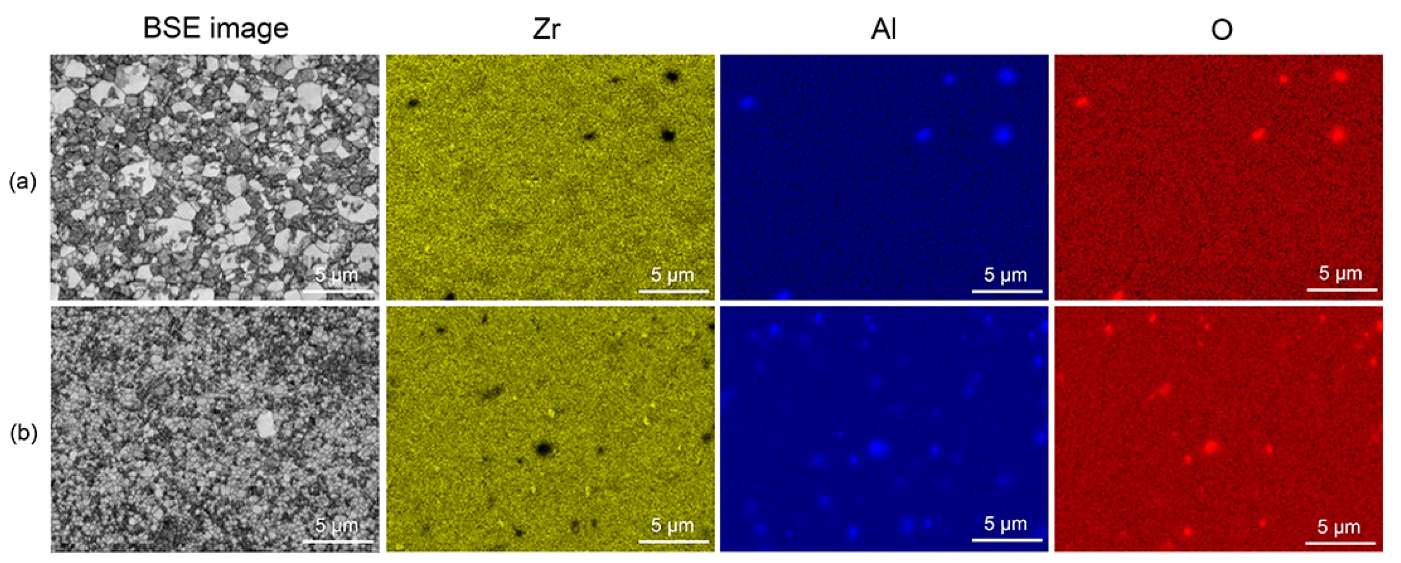
The results of EDS analysis of the two different Y-TZP ceramics are illustrated in
Figure 3. Although the pores and Al
2O
3 were not clearly distinguished in the ECC images (
Figure 1), the presence of Al
2O
3 within the ceramics was revealed by EDS elemental mapping. In the EDS images, the presence of pores was more frequently detected in the SLA specimens than in the SM specimens.
The EBSD maps of the SM and SLA ceramic specimens are presented in
Figure 4. The grain size and phase fraction of the ceramics derived from the EBSD images are also summarized in
Table 1. In general, the findings are in accordance with those of the XRD test (
Figure 2). The BC and IPF maps showed that the SLA ceramic was composed of finer grains (0.4 μm) than the SM ceramic (0.7 μm). Trunec [
24] reported that a longer time and higher temperature of sintering increase the grain size of the sintered zirconia body. In addition, the grain sizes (0.68 and 0.33 μm at 1600 °C and 1450 °C, respectively) obtained in a previous study [
24] resemble those in the current study. The Y-TZP ceramic surface is highly stress-sensitive, thus easily causing tetragonal-to-monoclinic (t–m) phase transformation [
26]. Therefore, extreme care should be taken in preparing and polishing zirconia samples for EBSD analysis to prevent such phase transformation on the surface [
27]. In this study, the ceramic specimens were polished very carefully using a diamond paste and finally 50 nm colloidal silica to avoid any residual stress in the surface layers during polishing [
28].
Flexural strength is an important property used to express indications for the clinical use of ceramics in dental restoration [
15].
Table 2 summarizes the flexural strength results of the SM and SLA Y-TZP ceramics, together with their respective Weibull parameters. The Weibull distributions of the flexural strength of the ceramics are presented in
Figure 5. For flexural strength, no significant difference was detected between the two ceramics (
p = 0.242). In ISO 6872 [
20], ceramics are divided into five classes based on their intended clinical use. In addition, for both materials, the mean flexural strength values satisfied the class 5 criteria (>800 MPa) in ISO 6872 [
20]. According to class 5 criteria, the recommended clinical indication is monolithic ceramic for the substructure of partial- or full-coverage prostheses of 4 units or more [
20]. However, the SM Y-TZP ceramic showed a slightly higher Weibull modulus than did the SLA ceramic, indicating slightly higher reliability and more narrowly distributed flexural strengths of the ceramic fabricated by the conventional method. As shown in
Figure 6, the fractured surfaces for both materials showed mixed intergranular and transgranular fractures [
29].
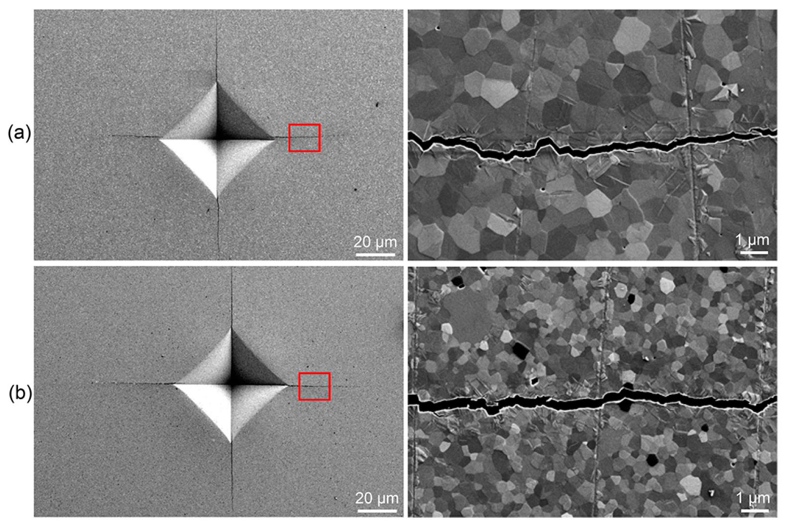
Figure 7 and
Table 3 show the fracture toughness data obtained based on the indentation fracture technique. The cracks in the two ceramics revealed a mixed mode involving intergranular and transgranular fractures [
30]. The hardness of Y-TZP ceramic tends to decrease with increasing grain size [
24]. Similar to the flexural strength results (
Table 2), however, there were no significant differences in either the Vickers hardness (
p = 0.480) or fracture toughness (
p = 0.101) between the SM and SLA ceramic materials. This may have been due to only a small difference in grain size between the two materials as well as their similar crystal structures.
The purpose of this study was to compare several aspects of Y-TZP ceramics prepared via conventional SM and new SLA techniques. The combined results showed that the two materials had relatively similar microstructures (
Figure 1,
Figure 2,
Figure 3 and
Figure 4) and thus statistically equivalent flexural strength (
Table 2) and fracture toughness (
Table 3). Therefore, the null hypothesis that there would be no difference in the microstructure, flexural strength, and fracture toughness between the SM and SLA Y-TZP ceramics was partially rejected. However, one should be cautious when generalizing the results directly to clinical situations. First of all, only one 3D-printing technique (SLA) was tested in this study. Further, only one commercial ceramic product per manufacturing technique was used, and their compositions were not completely identical. In addition, only 15 specimens for each ceramic, which is the minimum specified by the standard [
20], were prepared and tested for flexural strength measurements and Weibull analysis. For these analyses, a larger number of samples (at least 30) is preferred [
15]. Finally, a marginal fit evaluation of the crowns prepared by the two digital techniques was not included in the present study.
In addition, the building orientation can influence the flexural strength data of dental ceramics. When zirconia was fabricated with the DLP printing technique, vertically built (0°) samples achieved higher strength values than samples fabricated with oblique (45°) or horizontal (90°) build angles on the platform [
5]. The lower flexural strengths of 45-degree and 90-degree samples may have been attributable to more structural defects generated during the printing process. Therefore, for the appropriate calculation and comparison of the flexural strength of printed ceramics, considering the printing direction seems to be necessary.
AM technologies are a powerful alternative to conventional SM procedures, with several definite advantages, including the ability to produce complex geometries, the conservation of material, and the ability to form a body from multiple materials [
31]. In addition, these approaches can manufacture both fully sintered (solid) and partially sintered (more porous) ceramic structures [
31]. To confirm our findings, the dynamic mechanical properties, including the fatigue properties, of the newly developed SLA Y-TZP ceramic require scrutiny. In addition, the printing accuracy, esthetic performance, degeneration behavior, and biocompatibility of 3D-printed zirconia should be comprehensively studied to confirm successful applications of the material in clinical practice. To apply the new technology for the commercialization and utilization of 3D-printed ceramics, their quality, reliability, and clinical performance are still major issues to be solved.


 ,
, 


