Article

Controlling Electronic Energy Transfer: A Systematic Framework of Theory

by
David L. Andrews
* and
David S. Bradshaw
School of Chemistry, University of East Anglia, Norwich Research Park, Norwich NR4 7TJ, UK
*
Author to whom correspondence should be addressed.
Appl. Sci. 2022, 12(17), 8597; https://doi.org/10.3390/app12178597
Submission received: 28 July 2022 / Revised: 23 August 2022 / Accepted: 25 August 2022 / Published: 27 August 2022

Abstract

:
The transport of electronic excitation energy (EET) between ions, atoms, molecules or chromophores is an important process that occurs in a wide range of physical systems. The tantalising prospect of effective experimental control over such transfer is, in principle, amenable to a variety of different kinds of approach. Several of the most promising, which are analysed and compared in this paper, involve the influence of externally applied static electric or electromagnetic fields, or the exploitation of local media effects. A quantum electrodynamical framework is used as a common basis to describe the corresponding mechanisms, illustrated by specially adapted Feynman diagrams. It becomes evident that energy transfer between polar species engages an additional pairwise interaction beyond the EET coupling. Such an effect may also play an important role in interatomic Coulombic decay (ICD), a process that has recently attracted fresh interest. The control of ICD, in which the photoionisation of two nearby atoms via energy transfer, is determined to have analogous characteristics to conventional forms of EET.

1. Introduction

The absorption of ultraviolet–visible (UV-Visible) light by condensed phase dielectric materials generally results in the promotion of ions, atoms, molecules or chromophores to short-lived electronic excited states. In optically pure media that lack effective channels for complete energy dissipation, a degree of fluorescence will commonly ensue—yet the site of fluorescent emission will often differ from the site of initial excitation. In the short time interval between the photon absorption and emission events, single- or multi-step electronic energy transfer (EET) of the excitation may occur between proximal particles. Over short, sub-wavelength ranges, each such transfer step takes the form of a radiationless pairwise interaction, typically between electronically distinct particles. One of the particles (the excited particle, the initial absorber) acts as the energy donor, the other as an acceptor [1,2,3,4,5,6]. The present authors have reported on this phenomenon in various review articles [7,8,9,10].
Recently it has been shown that, fundamentally, the same mechanism also operates in atom physics, where photoexcitation of a donor atom leads to indirect ionisation of a nearby acceptor [11,12]. Here, too, the associated pairwise energy transfer can still be described in the same way as transfer between molecules or chromophores, based on a description cast in terms of quantised field interactions. There is, nonetheless, an important difference: in suitably complex, heterogeneous condensed phase media, multi-step resonance energy transfer may arise, usually exhibiting a spectroscopic gradient. This signifies that a small amount of energy is commonly lost through vibrational relaxation after each transfer step, which means that back transfer from each acceptor to its energy donor becomes exceptionally inefficient [13]. Similar effects can be observed in quantum dot systems [14,15,16,17,18].
An essential feature of EET (also known as resonance energy transfer, RET) is that the process occurs spontaneously, by engaging quanta of the vacuum field [19]. However, it has been shown that its efficiency and rate are amenable to modification by a variety of means [20,21,22,23,24,25,26,27], including local media effects and externally applied static electric or electromagnetic fields. In this paper, a comprehensive quantum electrodynamical framework is described in sufficient detail to explain the mechanism of inter-particle coupling in EET, providing a basis for theory that represents these more complex energy transfer systems. Adapting Feynman diagram methods, we establish results that exhibit fundamental connections between all these effects, also eliciting their detailed dependence on parameters that are under experimental control.

2. Electronic Energy Transfer

We begin with a straightforward representation of the electrodynamic coupling between the transition electric dipoles μ of a donor D, whose transition involves electronic relaxation, and μ of an acceptor A which undergoes an excitation. The two dipoles are separated by a displacement vector R = RDRA (i.e., the distance between the positions of D and A). Omitting a long and intricate derivation based on special functions [28], the matrix element for EET in the electric dipole (E1) approximation is as follows;
M f i = μ i ( D ) V i j ( k , R ) μ j ( A )
V i j ( k , R ) = e i k R 4 π ε 0 R 3 { ( 1 i k R ) ( δ i j 3 R ^ i R ^ j ) ( k R ) 2 ( δ i j R ^ i R ^ j ) }
In the above expression, subscripts i and j signify Cartesian components: here and throughout this paper, any such repeated indices are subject to implied summation (the Einstein index convention). Moreover, the subscript fi on M is standard notation meaning the matrix element for a transition from the initial to the final system state. The parameter k is the reciprocal of the reduced wavelength ƛ notionally associated with the transfer energy, i.e., k = 1 / ƛ = 2 π / λ where the transfer energy is h c / λ . The form of coupling represented by Equation (2) is known as the retarded resonance dipole–dipole interaction tensor; neglect of the imaginary part of this tensor leads to the monotonic distance-dependence being modified by an oscillatory function. Such behaviour arises in dimensionally constrained systems, such as cavities of finite length [20,29,30], though not in any open system.
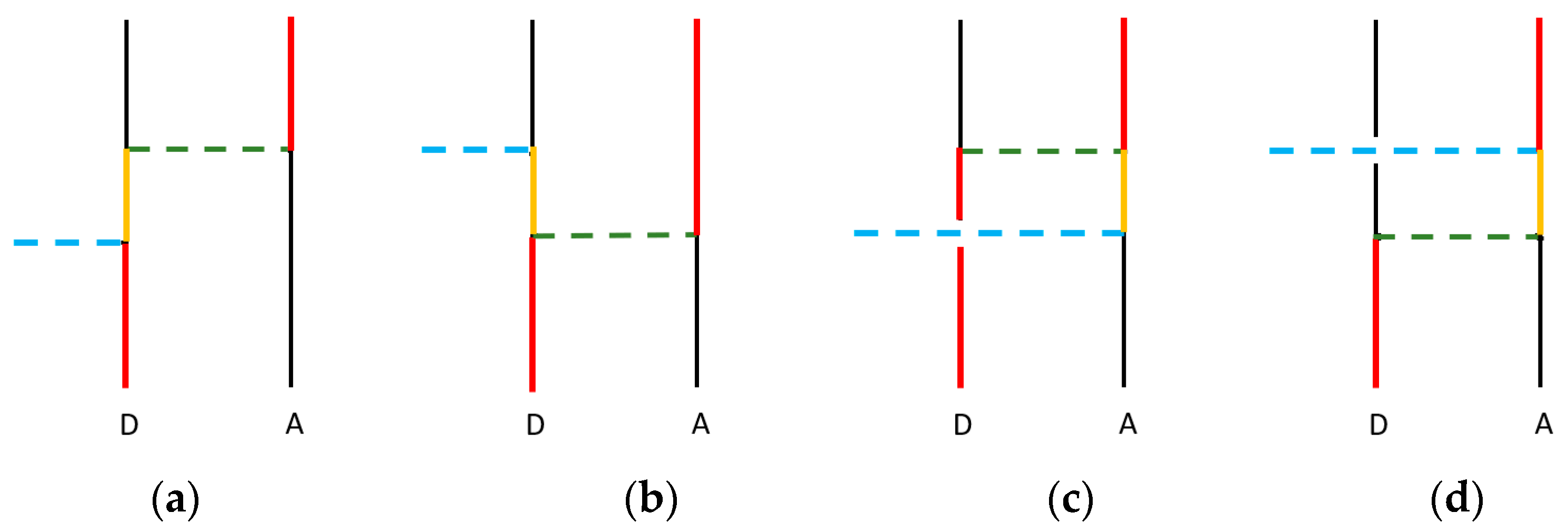
Equation (2) is routinely derived by quantum electrodynamical calculations adapting Feynman diagrammatic methods. Here, as shown in Figure 1a, colouring assists visualisation of the energy flow. With calculations of this kind, based on virtual photon coupling, the effects of quantum time-energy uncertainty require that two distinct time-orderings be taken into account. This reflects the fact that each dipole transition—the electronic decay of the donor and the excitation of the acceptor—can engage photon creation and annihilation operators only linearly. However, the sharply diminishing strength of coupling with distance, manifest in Equation (2), is such that EET generally occurs over distances where the term proportional to R−3 dominates. If consideration is limited to this regime, then it is possible (and expedient for the analysis that follows) to adopt a simplified, asymptotic representation formally consistent with treating Equation (2) as a first-order perturbation operator. Such a method was previously used to determine the dispersion interactions in the short-range region [31]. The corresponding single diagrammatic representation, exhibited in Figure 1b, essentially represents systems in which the energy transfer time (the interval between the release of electronic energy by the donor and its arrival at the acceptor) is itself immeasurably small, and whose duration is in practice experimentally indiscernible.
A more in-depth analysis of the derivation of the transition dipole-transition dipole (E1-E1) coupling tensor, Vij, and the transfer rate of EET (an outline of which follows)—without providing all of the intricate specifics—is delivered by Salam in his recent review [32]. The physical observable derived from the Vij tensor, via the matrix element, is the transfer rate of EET, symbolised by Γ. This rate is determined from the Fermi rule [33], which is given by Γ ~ | M f i | 2 when omitting a proportionality constant that corresponds to the spectral overlap of the donor emission and acceptor absorption [7,34]; the same constant of proportionality applies to all of the EET rate equations in our subsequent analysis. Assuming a system of two freely tumbling molecules, meaning that a rotational average is required [35], the following is found;
Γ EET ~ 2 | μ ( D ) | 2 | μ ( A ) | 2 3 ( 4 π ε 0 R 3 ) 2
It should be noted here that EET might, in principle, also occur via couplings between a transition dipole (E1) and higher order transition multipoles of either electric or magnetic form, or even through the interactions of two such multipoles. Commonly, the efficiencies of such effects are negligibly small in comparison to EET via E1-E1 coupling [10,36,37]—though exceptions may arise, as for example, in recent work by Wade et al. on ordered chiral materials, where magnetic dipole interactions come prominently into play [38].
When the process of energy transfer is modified by local fields, it is possible to approach theory by either of two alternative methods. One way is first to apply perturbation theory to correct the form of the donor and acceptor wavefunctions, taking into account the electromagnetic influence of these fields, then adopt these modified forms in evaluation of the correspondingly modified transition moments for direct inclusion in Equation (3). For example, under the influence of a static field all wavefunctions may be modified by a perturbation associated with the Stark effect; with throughput light the perturbation identifies with an AC Stark effect. In each case the alternative method, treating all the fundamental interactions in a single perturbation-based calculation, arrives at the results in a single step. Both methods yield the same results; we adopt the latter approach since it is correct, direct and the associated graphs lend clearer insights.

3. Controlled Energy Transfer

3.1. Static-Field Induced EET

It is somewhat surprising to observe that seemingly little attention has been given to the effect of local static electric fields on the process of electronic energy transfer. First, let us consider a static field whose strength, assumed to be uniform across the sample, is under direct experimental control. The most obvious evidence for the existence of any such effect, modifying the transfer efficiency, may be anticipated as a change in the relative intensities of fluorescence from the donor and acceptor [9]. For example, an enhanced rate of energy transfer, relative to donor emission, will lead to stronger fluorescence from the acceptor—unless the donor emission is itself modified to the same degree by the static field. In this respect, the surest guide to rate modification will be the specific effect of the static field on the acceptor.
For a given donor-acceptor pair in the solution phase, for which there is a free molecular orientation with respect to any fixed-direction, an externally applied field may correctly be assumed to negate any consistent effect on the rate of energy transfer. Much the same conclusion can be drawn for any randomly oriented ensemble of donors and acceptors in a solid, heterogeneous medium. In any such system (provided that the rotational relaxation times exceed the emission timescales), one might only expect a marginally broadened distribution of donor and acceptor fluorescence intensities. However, the situation is very different in the case of a medium in which the static field can affect the orientational distribution. An obvious instance is a doped liquid crystal, though the molecules in any polar liquid will experience the same effect to some degree. Indeed, the structure of most molecules have a sufficiently low symmetry to support a permanent electric dipole—specifically, those that belong to one of the Schoenflies point groups Cs, Cn or Cnv. The most familiar manifestation of alignment in a static field, featuring in the Debye equation, is the dipolar contribution to electronic polarisation [39].
There are two distinct mechanisms through which the applied electric field may modify observations of energy transfer [40]. One is by direct engagement in one of the electronic transitions—either the donor decay or the acceptor excitation; the other is through an effect on the relative alignment of those two components. The first of these effects requires that the given transition is allowed by both single-quantum (electric dipole, E1) and two-quantum (E12) selection rules. In fact, for polar molecules of every symmetry type, all of their conventional (i.e., E1-allowed) electronic transitions are also E12-allowed, so this condition is automatically satisfied. Nonetheless, the contribution of the latter, static field-engaging channel, will generally be small since it arises from a higher order of perturbation theory. The second mechanism for a field-induced change in the energy transfer rates, i.e., that which occurs through an influence on molecular orientation, arises from the conventional average value of the orientation factor—the 2/3 in Equation (3)—being modified as a result of partial alignment, commonly signified by a Boltzmann-weighted distribution function. As Van der Meer showed in a comprehensive analysis of the orientation factor known as ‘kappa squared’ [41], optimal alignment can enhance the rate of transfer by a factor of up to six (the isotropic value 2/3 increasing to an upper limit of 4). Methods for estimating the value of the orientation factor are discussed in a useful review by Loura [42].
The matrix element for EET is dominated by the input-field-independent term of Equation (2), but it also comprises correction terms that arise due to the presence of the static electric field. With respect to the first mechanism described above, the most significant process involves a linear coupling of the static field with either D or A. Simultaneous interactions with both are also possible, but their description entails a yet higher order of perturbation theory that contributes negligibly to the rate of energy transfer. The Fermi rate expression is again used to determine an observable, but in principle it now includes an extra term that represents a second-order molecular interaction, signifying one molecule (either the donor or the acceptor) coupling with both its neighbour and the input static electric field. This is written as Γ ~ | M f i + M f i stat | 2 , in which M f i stat accordingly represents an overall third-order correction term due to the static field. The structure of the correction term is readily ascertained from the simplified (near-zone) time-ordered diagrams shown in Figure 2. Hence, we find:
M f i stat = ε 0 D i { S i j ( D ) μ k ( A ) + μ k ( D ) S i j ( A ) } V j k ( 0 , R )
where ε0 is the vacuum permittivity, D is the local electric displacement field and Sij is a second rank (E12) response tensor. Specifically including the state connections and frequency arguments of the latter, the donor tensor takes the form S i j ( D ) S i j ( c k ; 0 ) and, for the acceptor, we have S i j ( A ) S i j ( 0 ; c k ) . Both tensors are fully defined in the original paper [40], which majors on the selection rules and an orientational averaging. In Equation (4), the first term relates summed contributions from both (a) and (b) in Figure 2; the second term is derived from both (c) and (d). Moreover, since the system resides in the near-zone region, the static limit (for which k = 0) of Equation (2) can be used—while the explicit frequency dependence of the S tensors, representing their dispersion property, needs to be retained.
In the relatively unusual case of entirely nonpolar donor and acceptor molecules, the rate of transfer delivered by the matrix element (4) without any input-field-independent contributions will clearly lead, through the Fermi Rule, to a transfer rate with a quadratic dependence on the applied field strength D, so that:
Γ STAT ~ D 2 3 ( 4 π R 3 ) 2 | μ ( D ) | 2 | Tr S ( A ) | 2 + | Tr S ( D ) | 2 | μ ( A ) | 2
More generally, in the case of orientable molecules, the general outcome from the original study [40] results from a derivation requiring the evaluation of Boltzmann-weighted tensor averages [43], and it is duly cast in a form that entails spherical Bessel functions. However, simplification can now be effected for the short-range effects that dominate energy transfer, where E1 processes are pre-eminent. With a Taylor series expansion of Equation (31) from ref. [40], we thus find for partially oriented systems:
Γ STAT ~ | μ ( D ) | 2 | μ ( A ) | 2 D 4 12 ( π ε 0 3 R 3 ) 2 ( k B T ) 4 Δ μ z 2 ( D ) μ 2 ( D ) Δ μ z 2 ( A ) μ 2 ( A )
Here, the absence of superscript arrows on μ designates a static dipole moment, whose direction within each molecule represents an internal axis chosen to define its intrinsic z-direction—i.e., the zD-axis within the donor and the zA-axis within the acceptor, given that each is polar; T is the absolute temperature and kB is the Boltzmann constant. The mechanism of mutual orientation that generates the above result applies only when both donor and acceptor are polar; the inverse fourth power dependence on temperature indicates a sharp diminution of the mutual orientation effect as temperature rises, since randomising thermal motions become increasingly dominant. In this result, there is also a notable dependence on the relative internal orientation of each transition dipole with respect to the corresponding static dipole, as signified by the two factors defined as Δ μ z 2 3 μ z 2 | μ | 2 = 2 μ z 2 μ x 2 μ y 2 in Equation (6). Evidently the effect is optimised if the transition and static dipoles have a common orientation, signifying that the relevant excited state has the symmetry of a totally symmetric representation in the relevant point group.
It is worth emphasizing the unique fourth power dependence on the strength of the applied static field D, which affords a sensitivity that is especially amenable to experimental validation. Wherever field-induced orientation occurs, any corrections associated with the mechanism of direct engagement with the applied field will only furnish terms with a still higher order dependence on the field strength.
The above analysis has focused on a case where a uniform applied field permeates the energy transfer system. However, static field effects can also be produced by local molecular dipoles—as, for example, in structurally ordered media or at surfaces [44]—where intrinsic local fields may exert another kind of influence on observed energy transfer effects. This is the topic of the next Section.

3.2. Static-Dipole Induced EET

Typically, EET is described in terms of a coupling between electronically isolated molecules. In practice, however, most systems comprise numerous nearby atoms, molecules or chromophores whose presence may alter the surrounding electronic environment and, thus, affect any pairwise energy transfer events. Such non-participating entities (i.e., those not directly involved in the pairwise EET) are known as a ‘third body’ and they are often labelled by M. In recent times, the possibility of M exerting an influence on the rate of donor-acceptor transfer has received much more attention [29,45,46,47,48,49,50,51]. Such work has verified that these nearby entities, especially any that are strongly polar, may substantially affect the energy transfer rate without themselves having an overall change in state (namely, their initial and final state are identical). In consequence, the physical introduction of ancillary molecules, suitably positioned to act in the capacity of a passive third body, offers a route to control the energy transfer efficiency.
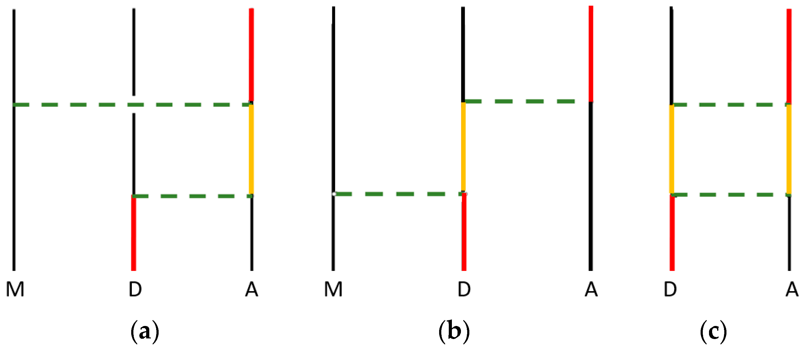
It is imperative that third body influences are considered in systems that contain closely spaced chromophores, such as those within light-harvesting materials. Indeed, for all condensed phase applications, it should be borne in mind that the single entity termed the third body, in the following analysis, will almost always be one of many close neighbours—representing many species whose effects on a specific energy transfer process will give additive contributions to the matrix element. By the inclusion of any individual third body, the expression for the correction term of the total rate becomes more complicated. For the mechanisms exemplified by Figure 3a, where the static dipole of M interacts with A, and the corresponding situation coupling M with D, represented by Figure 3b, the net result is written as;
M f i 3 - body = μ i ( D ) V i j ( 0 , R ) S j k ( A ) V k l ( 0 , R AM ) μ l ( M ) + μ i ( M ) V i j ( 0 , R MD ) S j k ( D ) V k l ( 0 , R ) μ l ( A )
where μ is the static dipole moment of M, up and down arrow superscripts denote excitation and decay transitions, and RAM = RARM is the displacement between A and M (RMD is for M and D). Note that when constructing each of the terms shown in Equation (7), an additional contribution is also taken into account, in which the temporal order of the interactions is inverted; these must also be considered to achieve the correct results, which are fully provided in ref. [48].
Whenever energy transfer occurs in the vicinity of a third body M, one other term always arises in the matrix element. This term, engaging the electronic polarisation rather than the static dipole of M, can be considered a background, dynamic interaction that is not directly controllable. For any significantly polar third body, this contribution arising from a higher order of perturbation theory can be anticipated to have a relatively small effect on the efficiency of the EET, but for non-polar species it represents the only local-field correction. Although it is seldom significant, for completeness in this account it is fully expressed as follows;
M f i 3 - body | background = μ i ( D ) V i j ( 0 , R DM ) S j k ( M ) V k l ( 0 , R AM ) μ l ( A )
in which S j k ( M ) is not a transition tensor but corresponds to the dynamic polarisability of M at the frequency of the conveyed energy.
Irrespective of any neighbouring third body, another intriguing effect arises when D and A are both polar, in which case a coupling of the static dipoles can take place alongside the energy transfer, as illustrated in Figure 3c. This feature, which is seldom given sufficient scrutiny in studies on EET, generates a matrix element whose main contribution can be secured on the basis of two-level approximations for D and for A. The result is expressible as follows [44];
M f i polar = ( 1 c k ) V j k ( 0 , R ) V i l ( 0 , R ) μ i ( D ) μ j ( A ) × [ μ k ( D ) μ l ( A ) μ k * ( D ) μ l * ( A ) ]
This result exhibits an interesting dependence on three types of dipole, for each species. As before, the decay and excitation transition dipoles here carry arrow superscripts; dipoles without a superscript denote electronic ground state dipoles and those with an asterisk signify static dipoles in the relevant electronic excited states. It emerges that if either the donor or the acceptor has a negligible difference between its ground and excited state dipole—as will occur if those two states have a similar nuclear geometry—then the above expression becomes simply proportional to the vector dipole shift of the other species. This linear dependence is a feature that also arises in the theory of solvatochromism [52], thereby enabling a quantitative assessment of the relevance of this dipole-coupling effect on EET; more detail is given in ref. [44]. The general mechanism represented by Figure 3c is especially pertinent to the specific case of interatomic Coulombic decay; we return to consider this connection in Section 4. First, however, we now analysis the effects on EET of an input beam of off-resonant laser radiation.

3.3. Optically Controlled EET

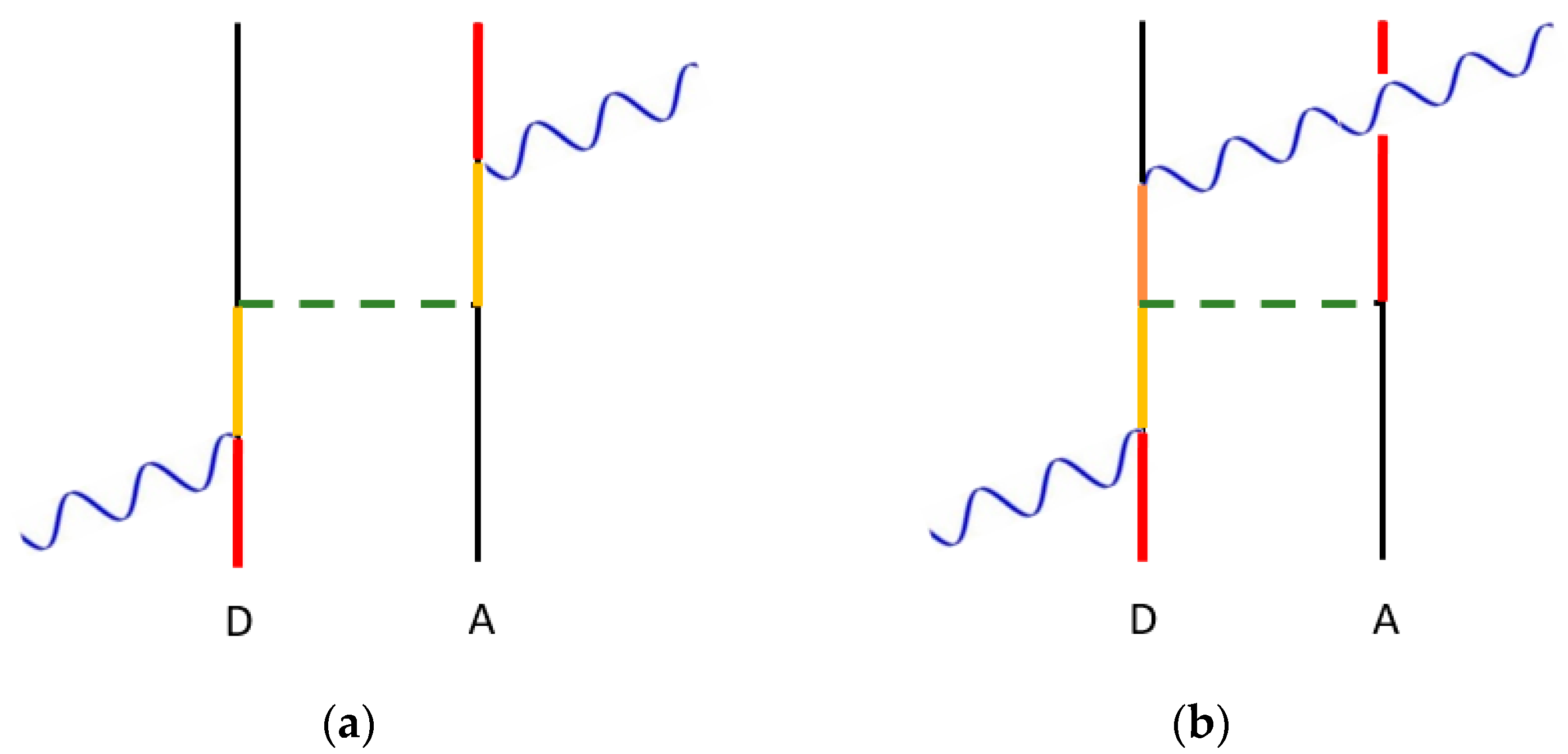
Another strategy to produce a modification to the efficiency of energy transfer involves the input of an off-resonant (i.e., a non-absorbing) laser beam of sufficient intensity. Depending on a number of factors, the rate of transfer can be enhanced or reduced [53,54]. The equation representing an observable for this case is again derived from the Fermi rate expression; it now includes an extra term that corresponds to an overall fourth-order interaction with respect to D and A. This is written as Γ ~ | M f i + M f i dyn | 2 , in which M f i dyn is a correction term that arises due to the input of the dynamic electromagnetic field. In detail, again presuming that D and A are in close proximity, M f i dyn is representative of the energy transfer interactions taking place as part of a concerted quantum process. This involves four possible fourth-order interactions: second-order molecular interactions at D and A, in which the input beam is absorbed at D and emitted back into the beam at A or vice versa (the former is shown in Figure 4a), or third-order molecular interactions at either D or A, where the input beam is absorbed and emitted at the same molecule (Figure 4b displays the case when this occurs at D). Therefore, in this near-zone region that is again represented by the static limit, the explicit form of M f i dyn is given by;
M f i dyn = ( I 2 ε 0 c ) e i e ¯ l V j k ( 0 , R ) ( S i j ( D ) S l k (   A ) + S i j ( A ) S l k ( D ) + T i j l ( D ) μ k (   A ) + T i j l (   A ) μ k (   D ) )
Here, S is a transition polarisability, explicitly written as S ( D ) S ( c ( k + k ) ; c k ) and S ( A ) S ( c k ; c ( k + k ) ) , where k is the wave-vector of the input photons. Moreover, Tijl is a transition hyperpolarisability, i.e., T i j l ( D ) T i j l ( c k , c k ; c k ) and T i j l ( A ) T i j l ( c k ; c k , c k ) , while I and e are the intensity and polarisation of the throughput beam, respectively. For entirely nonpolar donor and acceptor molecules, the rate expression for the optically controlled EET (otherwise known as laser-assisted RET or LARET) is then written as;
Γ LARET = V j k ( 0 , R ) V m n ( 0 , R ) { μ j ( D ) μ k ( A ) μ m ( D ) μ n ( A ) + ( I 2 c ε 0 ) e i e ¯ l × μ m ( D ) μ n ( A ) ( S i j ( D ) S l k (   A ) + S i j ( A ) S l k ( D ) ) +   }
Here, the first term is the EET rate that denotes an input-field-independent contribution, and the second term (which has the next largest magnitude since its linear, not quadratic, in I) is based on a quantum interference between the EET term and the fourth-order input beam terms. Note that the transition hyperpolarisability terms are omitted because of the assumption that the molecules are nonpolar.
With the very rare exception of molecules with icosahedral symmetry, all transitions that are single-quantum electric dipole (E1) allowed are also allowed in a three-quantum (E13) process [55]. Hence, mechanism (b) will always be effective in, to some degree, modifying EET efficiency when D and A are polar, whereas mechanism (a) provides a basis to switch on transfer processes between states that would otherwise not be allowed.
Examining the latter in more detail, we now analyse the case of coupling between a non-polar donor and acceptor whose transitions are electric dipole (E1) forbidden but two-quantum (E12) allowed. This signifies that the initial excitation of the donor cannot occur via direct one-photon absorption but, for example, may involve initial excitation to a higher energy electronic state followed by relaxation. In such a case, only terms involving the transition polarisability arise, since they represent two-quantum allowed transitions at D and A, i.e., the absorption (or emission) of the input beam and the energy transfer interaction. Here, since this system is electric dipole (E1) forbidden, EET could not, in the absence of a beam, occur—except via extremely weak higher multipole interactions (associated with exceptionally sharp R-n dependence of the rate, where n 6 ). Therefore, energy transfer can only reasonably occur when the input beam is applied; this is the origin of the switching action. For this scheme, since the input-field-independent contribution does not arise, Equation (11) is null and the leading term of the rate, which is dependent on I2, then becomes;
Γ SWITCH = V j k ( 0 , R ) V m n ( 0 , R ) { ( I 2 4 c 2 ε 0 2 ) e i e ¯ l e q e ¯ p ( S i j ( D ) S l k (   A ) + S i j ( A ) S l k ( D ) ) ( S p m ( D ) S q n (   A ) + S p m ( A ) S q n ( D ) ) }
which is the term that represents the possibility of all-optical switching [56,57,58]. The effect of an off-resonant throughput beam on simple optical processes is covered in our recent review article [59]. Another feasible system, based on this form of all-optical switching, is known as an optical transistor. Here, it is estimated that stimulated emission might be increased by up to 16 orders of magnitude, on input of an off-resonant input beam with sufficient intensity, for a three-level population-inverted material pumped just below its lasing threshold [60].

4. Interatomic Coulombic Decay

The fundamental electrodynamic mechanism of EET plays a role in other photonic interactions too numerous to detail here. However, it is interesting to briefly focus on a recently emerging phenomenon, in which EET plays such a role: interatomic Coulombic decay (ICD) [61,62,63,64,65]. This process bears the hallmark R−6 distance dependence of EET in the near-zone region, but the energy it transfers between atoms is associated with electromagnetic radiation in the X-ray range. Moreover, compared to molecular EET, much more complex prior and posterior processes occur.
In essence, ICD is the photoionization of an atom leading to photoionization of another nearby atom through exchange of a high energy quantum, mediated in the form of a virtual photon. The steps involved are as follows: (i) on input of incident X-ray radiation, donor D is photoionized via ejection of an inner shell electron; (ii) the energy released as an outer electron relaxes into this vacancy is transferred from D to A, and then; (iii) acceptor A is also photoionized since the transferred energy expels an outer electron from the atom; in consequence (iv) the newly charged atoms repel each other and move apart. A practical example is the decay of Ne2 via electron emission, in which the interactions of the created ions cause fragmentation of this dimer in a ‘Coulomb explosion’ [66].
Step (ii) is clearly analogous to molecular EET, but the associated mechanism is not the simple process of Equation (1) since the static field effects of the newly formed donor ion should also be taken into account. Therefore, the relevant mechanism is the one depicted by the Feynman diagram of Figure 3c. Here, following the initial step that expels the electron to form the ion, the donor is in an energetically unfavourable configuration that is analogous to an excited donor in molecular EET. There are then two quasi-simultaneous interactions between D and A, one involving the energy transfer and the other the static field effects on A due to D. In contrast to molecular EET, where the energy migration from D to A simply excites the acceptor from its ground state (i.e., an electron is promoted to a higher quantized state), the acceptor in the ICD mechanism is ionised because the transfer energy is in the high-frequency X-ray range; in consequence, an outer electron is excited to the continuum. The energy transfer step can be represented by the follow matrix element [67]:
M f i polar = r , s μ i r α ( D ) μ j 0 r ( D ) μ k s 0 ( A ) μ l β s ( A ) V i k ( 0 , R ) V j l ( 0 , R ) E α ( D ) E r ( D ) + E 0 ( A ) E s ( A )
where r and s are the virtual intermediate states that also appear in the explicit form of the S tensors referred to in previous equations. Moreover, α and β are the excited states of D and A, respectively; atomic energies are denoted by E with 0 signifying the ground state. In this general expression, forsaking a two-level approximation that is no longer appropriate, the summations over r and s naturally excludes any system state that matches the initial or final system state. Equation (13) is in fact the generic precursor to Equation (9), whose derivation explicitly discounts intermediate states that fall foul of this matching rule.
Despite this basic comparison of the energy transfer step of ICD with molecular EET, the ICD process is much more complex. ICD often operates in the ultra-near-zone region, meaning that wavefunction overlap can arise, and thus contributions corresponding to electron correlation and exchange need to be considered. Furthermore, account also needs to be taken of the Auger effect [68], since there is electron relaxation from a valence shell to the core shell in D. This competing effect involves the generated energy from such an event transferring to another electron within D (thus causing its ejection) and, as a result, energy transfer between D and A is not possible. An overview of these additional considerations is provided in a review by Jahnke [69]. The theoretical developments of ICD significantly mirror those established in molecular EET—such as the effects of retardation and virtual photons—and, as such, it can also be controlled via surrounding dielectric environments and third bodies [12,70]. While application of a static electric field would be disruptive to observations of ICD, it is still the case that an applied off-resonant field could be engaged as a control mechanism, as discussed earlier. A potential advantage, in the case of an atomic system, is that the relative sparsity and discreteness of energy levels (compared to any molecule) would facilitate judicious choice of a suitably off-resonant wavelength for the applied beam.

5. Conclusions

Using comprehensive quantum theory and a Feynman diagram approach, a range of electrodynamic mechanisms has been shown to provide a route to control energy transfer through the influence of static or electromagnetic fields. Connections have also been established to a related effect that arises in energy transfer between polar molecules—where theory demands the inclusion of an additional coupling effect beyond conventional EET. It is this mechanism that is also most pertinent to interatomic Coulombic decay, i.e., a relatively new phenomena in which two nearby atoms are photoionised via energy transfer. Recognizing the fundamental connections between these processes offers new prospects for identifying control mechanisms across the full range of EET systems.

Author Contributions

The contributions of the authors to this Article are D.L.A. 50% and D.S.B. 50%. Conceptualization, D.L.A. and D.S.B.; methodology, D.L.A. and D.S.B.; formal analysis, D.L.A. and D.S.B.; investigation, D.L.A. and D.S.B.; writing—original draft preparation, D.L.A. and D.S.B.; writing—review and editing, D.L.A. and D.S.B.; visualization, D.L.A. All authors have read and agreed to the published version of the manuscript.

Funding

This research received no external funding.

Acknowledgments

We are grateful to our colleague Kayn Forbes for a variety of useful comments.

Conflicts of Interest

The authors declare no conflict of interest.

References

  1. Andrews, D.L.; Demidov, A.A. Resonance Energy Transfer; Wiley: Chichester, UK, 1999. [Google Scholar]
  2. May, V.; Kühn, O. Charge and Energy Transfer Dynamics in Molecular Systems; John Wiley & Sons: Hoboken, NJ, USA, 2008. [Google Scholar]
  3. Salam, A. Molecular Quantum Electrodynamics. Long-Range Intermolecular Interactions; Wiley: Hoboken, NJ, USA, 2010. [Google Scholar]
  4. Medintz, I.; Hildebrandt, N. Förster Resonance Energy Transfer: From Theory to Applications; Wiley-VCH: Weinheim, Germany, 2013. [Google Scholar]
  5. Valeur, B.; Berberan-Santos, M.N. Molecular Fluorescence: Principles and Applications, 2nd ed.; Wiley-VCH: Weinheim, Germany, 2013. [Google Scholar]
  6. Andrews, D.L.; Lipson, R.H. Molecular Photophysics and Spectroscopy, 2nd ed.; IOP Publishing: Bristol, UK, 2021. [Google Scholar]
  7. Juzeliūnas, G.; Andrews, D.L. Quantum electrodynamics of resonance energy transfer. Adv. Chem. Phys. 2000, 112, 357–410. [Google Scholar]
  8. Andrews, D.L. Mechanistic principles and applications of resonance energy transfer. Can. J. Chem. 2008, 86, 855–870. [Google Scholar] [CrossRef]
  9. Andrews, D.L.; Bradshaw, D.S. Resonance energy transfer. In Encyclopedia of Applied Specteoscopy; Andrews, D.L., Ed.; Wiley-VCH: Weinheim, Germany, 2009; pp. 533–554. [Google Scholar]
  10. Jones, G.A.; Bradshaw, D.S. Resonance energy transfer: From fundamental theory to recent applications. Front. Phys. 2019, 7, 100. [Google Scholar] [CrossRef]
  11. Marburger, S.; Kugeler, O.; Hergenhahn, U.; Möller, T. Experimental evidence for interatomic coulombic decay in Ne clusters. Phys. Rev. Lett. 2003, 90, 203401. [Google Scholar] [CrossRef] [PubMed]
  12. Bennett, R.; Votavová, P.; Kolorenč, P.; Miteva, T.; Sisourat, N.; Buhmann, S.Y. Virtual photon approximation for three-body interatomic coulombic decay. Phys. Rev. Lett. 2019, 122, 153401. [Google Scholar] [CrossRef] [PubMed]
  13. Andrews, D.L.; Rodríguez, J. Resonance energy transfer: Spectral overlap, efficiency, and direction. J. Chem. Phys. 2007, 127, 084509. [Google Scholar] [CrossRef] [PubMed]
  14. Lovett, B.W.; Reina, J.H.; Nazir, A.; Kothari, B.; Briggs, G.A.D. Resonant transfer of excitons and quantum computation. Phys. Lett. A 2003, 315, 136–142. [Google Scholar] [CrossRef]
  15. Scholes, G.D.; Andrews, D.L. Resonance energy transfer and quantum dots. Phys. Rev. B 2005, 72, 125331. [Google Scholar] [CrossRef]
  16. Kawazoe, T.; Kobayashi, K.; Ohtsu, M. Optical nanofountain: A biomimetic device that concentrates optical energy in a nanometric area. Appl. Phys. Lett. 2005, 86, 103102. [Google Scholar] [CrossRef]
  17. Wegner, K.D.; Jin, Z.; Lindén, S.; Jennings, T.L.; Hildebrandt, N. Quantum-dot-based Förster resonance energy transfer immunoassay for sensitive clinical diagnostics of low-volume serum samples. ACS Nano 2013, 7, 7411–7419. [Google Scholar] [CrossRef]
  18. Higgins, L.J.; Marocico, C.A.; Karanikolas, V.D.; Bell, A.P.; Gough, J.J.; Murphy, G.P.; Parbrook, P.J.; Bradley, A.L. Influence of plasmonic array geometry on energy transfer from a quantum well to a quantum dot layer. Nanoscale 2016, 8, 18170–18179. [Google Scholar] [CrossRef] [PubMed] [Green Version]
  19. Andrews, D.L.; Bradshaw, D.S. Virtual photons, dipole fields and energy transfer: A quantum electrodynamical approach. Eur. J. Phys. 2004, 25, 845–858. [Google Scholar] [CrossRef]
  20. Andrew, P.; Barnes, W.L. Förster energy transfer in an optical microcavity. Science 2000, 290, 785–788. [Google Scholar] [CrossRef] [PubMed]
  21. Nakamura, T.; Fujii, M.; Miura, S.; Inui, M.; Hayashi, S. Enhancement and suppression of energy transfer from Si nanocrystals to Er ions through a control of the photonic mode density. Phys. Rev. B 2006, 74, 045302. [Google Scholar] [CrossRef]
  22. Zhao, L.; Ming, T.; Shao, L.; Chen, H.; Wang, J. Plasmon-controlled Förster resonance energy transfer. J. Phys. Chem. C 2012, 116, 8287–8296. [Google Scholar] [CrossRef]
  23. Ghenuche, P.; de Torres, J.; Moparthi, S.B.; Grigoriev, V.; Wenger, J. Nanophotonic enhancement of the Förster resonance energy-transfer rate with single nanoapertures. Nano Lett. 2014, 14, 4707–4714. [Google Scholar] [CrossRef]
  24. Hsu, L.-Y.; Ding, W.; Schatz, G.C. Plasmon-coupled resonance energy transfer. J. Phys. Chem. Lett. 2017, 8, 2357–2367. [Google Scholar] [CrossRef]
  25. Cortes, C.L.; Jacob, Z. Fundamental figures of merit for engineering Förster resonance energy transfer. Opt. Express 2018, 26, 19371–19387. [Google Scholar] [CrossRef]
  26. Roth, D.J.; Nasir, M.E.; Ginzburg, P.; Wang, P.; Le Marois, A.; Suhling, K.; Richards, D.; Zayats, A.V. Förster resonance energy transfer inside hyperbolic metamaterials. ACS Photonics 2018, 5, 4594–4603. [Google Scholar] [CrossRef]
  27. Wei, Y.-C.; Lee, M.-W.; Chou, P.-T.; Scholes, G.D.; Schatz, G.C.; Hsu, L.-Y. Can nanocavities significantly enhance resonance energy transfer in a single donor–acceptor pair? J. Phys. Chem. C 2021, 125, 18119–18128. [Google Scholar] [CrossRef]
  28. Daniels, G.J.; Jenkins, R.D.; Bradshaw, D.S.; Andrews, D.L. Resonance energy transfer: The unified theory revisited. J. Chem. Phys. 2003, 119, 2264–2274. [Google Scholar] [CrossRef] [Green Version]
  29. Weeraddana, D.; Premaratne, M.; Andrews, D.L. Direct and third-body mediated resonance energy transfer in dimensionally constrained nanostructures. Phys. Rev. B 2015, 92, 035128. [Google Scholar] [CrossRef]
  30. Fiscelli, G.; Rizzuto, L.; Passante, R. Resonance energy transfer between two atoms in a conducting cylindrical waveguide. Phys. Rev. A 2018, 98, 013849. [Google Scholar] [CrossRef]
  31. Andrews, D.L.; Bradshaw, D.S.; Leeder, J.M.; Rodríguez, J. Dynamics of the dispersion interaction in an energy transfer system. Phys. Chem. Chem. Phys. 2008, 10, 5250–5255. [Google Scholar] [CrossRef] [PubMed]
  32. Salam, A. The unified theory of resonance energy transfer according to molecular quantum electrodynamics. Atoms 2018, 6, 56. [Google Scholar] [CrossRef]
  33. Fermi, E. Nuclear Physics; University of Chicago Press: Chicago, IL, USA, 1950. [Google Scholar]
  34. Scholes, G.D. Long-range resonance energy transfer in molecular systems. Annu. Rev. Phys. Chem. 2003, 54, 57–87. [Google Scholar] [CrossRef]
  35. Andrews, D.L.; Thirunamachandran, T. On three-dimensional rotational averages. J. Chem. Phys. 1977, 67, 5026–5033. [Google Scholar] [CrossRef]
  36. Salam, A. A general formula for the rate of resonant transfer of energy between two electric multipole moments of arbitrary order using molecular quantum electrodynamics. J. Chem. Phys. 2005, 122, 044112. [Google Scholar] [CrossRef]
  37. Grinter, R.; Jones, G.A. Interpreting angular momentum transfer between electromagnetic multipoles using vector spherical harmonics. Opt. Lett. 2018, 43, 367–370. [Google Scholar] [CrossRef]
  38. Wade, J.; Brandt, J.R.; Reger, D.; Zinna, F.; Amsharov, K.Y.; Jux, N.; Andrews, D.L.; Fuchter, M.J. 500-fold amplification of small molecule circularly polarised luminescence through circularly polarised FRET. Angew. Chem. Int. Ed. 2021, 60, 222–227. [Google Scholar] [CrossRef]
  39. Atkins, P.; de Paula, J.; Keeler, L. Atkins’ Physical Chemistry, 11th ed.; Oxford University Press: Oxford, UK, 2018. [Google Scholar]
  40. Andrews, D.L.; Bittner, A.M. Energy-transfer in a static electric-field. J. Lumin. 1993, 55, 231–242. [Google Scholar]
  41. Van der Meer, B.W. Kappa-squared: From nuisance to new sense. Rev. Mol. Biotechnol. 2002, 82, 181–196. [Google Scholar] [CrossRef]
  42. Loura, L.M. Simple estimation of Förster resonance energy transfer (FRET) orientation factor distribution in membranes. Int. J. Mol. Sci. 2012, 13, 15252–15270. [Google Scholar] [PubMed]
  43. Andrews, D.L.; Harlow, M.J. Phased and Boltzmann-weighted rotational averages. Phys. Rev. A 1984, 29, 2796–2806. [Google Scholar] [CrossRef]
  44. Andrews, D.L. Effects of intrinsic local fields on molecular fluorescence and energy transfer: Dipole mechanisms and surface potentials. J. Phys. Chem. B 2019, 123, 5015–5023. [Google Scholar]
  45. Daniels, G.J.; Andrews, D.L. The electronic influence of a third body on resonance energy transfer. J. Chem. Phys. 2002, 116, 6701–6712. [Google Scholar] [CrossRef]
  46. Caprasecca, S.; Curutchet, C.; Mennucci, B. Toward a unified modeling of environment and bridge-mediated contributions to electronic energy transfer: A fully polarizable QM/MM/PCM approach. J. Chem. Theory Comput. 2012, 8, 4462–4473. [Google Scholar] [CrossRef] [PubMed]
  47. Salam, A. Mediation of resonance energy transfer by a third molecule. J. Chem. Phys. 2012, 136, 014509. [Google Scholar]
  48. Andrews, D.L.; Ford, J.S. Resonance energy transfer: Influence of neighboring matter absorbing in the wavelength region of the acceptor. J. Chem. Phys. 2013, 139, 014107. [Google Scholar]
  49. Salam, A. Near-zone mediation of RET by one and two proximal particles. J. Phys. Chem. A 2019, 123, 2853–2860. [Google Scholar]
  50. Salam, A. Bridge-mediated RET between two chiral molecules. App. Sci. 2021, 11, 1012. [Google Scholar]
  51. Salam, A. Pair and mediated RET between two chiral molecules. Mol. Phys. 2022, 120, e2094842. [Google Scholar]
  52. Suppan, P. Invited review solvatochromic shifts: The influence of the medium on the energy of electronic states. J. Photochem. Photobiol. A Chem. 1990, 50, 293–330. [Google Scholar]
  53. Allcock, P.; Jenkins, R.D.; Andrews, D.L. Laser assisted resonance energy transfer. Chem. Phys. Lett. 1999, 301, 228–234. [Google Scholar]
  54. Allcock, P.; Jenkins, R.D.; Andrews, D.L. Laser-assisted resonance-energy transfer. Phys. Rev. A 2000, 61, 023812. [Google Scholar]
  55. Andrews, D.L. Symmetry characterization in molecular multiphoton spectroscopy. Spectrochim. Acta Part A 1990, 46, 871–885. [Google Scholar]
  56. Bradshaw, D.S.; Andrews, D.L. Optically controlled resonance energy transfer: Mechanism and configuration for all-optical switching. J. Chem. Phys. 2008, 128, 144506. [Google Scholar]
  57. Bradshaw, D.S.; Andrews, D.L. All-optical switching based on controlled energy transfer between nanoparticles in film arrays. J. Nanophotonics 2009, 3, 031503. [Google Scholar]
  58. Bradshaw, D.S.; Andrews, D.L. All-optical switching between quantum dot nanoarrays. Superlatt. Microstruct. 2010, 47, 308–313. [Google Scholar]
  59. Bradshaw, D.S.; Forbes, K.A.; Andrews, D.L. Off-resonance control and all-optical switching: Expanded dimensions in nonlinear optics. App. Sci. 2019, 9, 4252. [Google Scholar]
  60. Andrews, D.L.; Bradshaw, D.S. Off-resonant activation of optical emission. Opt. Commun. 2010, 283, 4365–4367. [Google Scholar]
  61. Cederbaum, L.S.; Zobeley, J.; Tarantelli, F. Giant intermolecular decay and fragmentation of clusters. Phys. Rev. Lett. 1997, 79, 4778–4781. [Google Scholar]
  62. Santra, R.; Zobeley, J.; Cederbaum, L.S.; Moiseyev, N. Interatomic coulombic decay in van der Waals clusters and impact of nuclear motion. Phys. Rev. Lett. 2000, 85, 4490–4493. [Google Scholar] [PubMed]
  63. Santra, R.; Zobeley, J.; Cederbaum, L.S. Electronic decay of valence holes in clusters and condensed matter. Phys. Rev. B 2001, 64, 245104. [Google Scholar]
  64. Jahnke, T.; Czasch, A.; Schöffler, M.; Schössler, S.; Knapp, A.; Käsz, M.; Titze, J.; Wimmer, C.; Kreidi, K.; Grisenti, R. Experimental observation of interatomic Coulombic decay in neon dimers. Phys. Rev. Lett. 2004, 93, 163401. [Google Scholar] [CrossRef]
  65. Trinter, F.; Williams, J.; Weller, M.; Waitz, M.; Pitzer, M.; Voigtsberger, J.; Schober, C.; Kastirke, G.; Müller, C.; Goihl, C. Evolution of interatomic Coulombic decay in the time domain. Phys. Rev. Lett. 2013, 111, 093401. [Google Scholar]
  66. Scheit, S.; Cederbaum, L.S.; Meyer, H.D. Time-dependent interplay between electron emission and fragmentation in the interatomic Coulombic decay. J. Chem. Phys. 2003, 118, 2092–2107. [Google Scholar]
  67. Andrews, D.L.; Leeder, J.M. Resonance energy transfer: When a dipole fails. J. Chem. Phys. 2009, 130, 184504. [Google Scholar]
  68. Franz, J.; Bennett, R.; Buhmann, S.Y. Auger decay in dispersing and absorbing environments. Phys. Rev. A 2021, 104, 013103. [Google Scholar]
  69. Jahnke, T. Interatomic and intermolecular Coulombic decay: The coming of age story. J. Phys. B At. Mol. Opt. Phys. 2015, 48, 082001. [Google Scholar]
  70. Hemmerich, J.L.; Bennett, R.; Buhmann, S.Y. The influence of retardation and dielectric environments on interatomic Coulombic decay. Nat. Commun. 2018, 9, 2934. [Google Scholar] [PubMed]
Figure 1. Graphs for calculating the basic matrix element for electronic energy transfer, in which time is progressing upwards: (a) two separate time-orderings accounting for causality and (b) representation of the conflated result obtained from a near-zone approximation, in which R ƛ . In the vertical world-lines for D and A, red segments indicate an electronic excited state and black is the ground state. Between the two world-lines is a wavy green line that denotes virtual photon propagation; the horizontal dashed line indicates short-range dipole–dipole coupling.
Applsci 12 08597 g001
Figure 2. Near-zone graphs for calculating the matrix element for electronic energy transfer that linearly engages with a static electric field: in (a,b) the static field influences the donor decay transition; in (c,d) it affects the acceptor excitation. Red and black lines denote electronically excited and ground states, respectively; a yellow line denotes a virtual intermediate state. The blue dashed line indicates the applied static field, while the green dashed line denotes short-range dipole–dipole coupling.
Applsci 12 08597 g002
Figure 3. Representative near-zone graphs for calculating the matrix element for electronic energy transfer between a donor D and an acceptor A, modified by the electronic influence of a local electric dipole: (a) one of two time-orderings for the effect of a neighbouring third-body static dipole M on the acceptor A; (b) the other contribution, where M engages with the donor D; (c) the effect of static dipoles held by D and A. Colour coding as in Figure 2.
Applsci 12 08597 g003
Figure 4. Representative near-zone graphs for calculating the matrix element for electronic energy transfer between a donor D and an acceptor A, under the influence of a throughput off-resonance laser beam: (a) contribution for transfer satisfying two-quantum selection rules at D and A; (b) contribution when the input beam is absorbed and emitted at D while it simultaneously interacts with A. Colour coding as in Figure 2; the orange line segment again indicates a virtual intermediate state, which need not be the same as for the yellow segment preceding it.
Applsci 12 08597 g004
Publisher’s Note: MDPI stays neutral with regard to jurisdictional claims in published maps and institutional affiliations.