Article

A Novel Reference Governor for Disturbance Observer-Based Load Pressure Control in a Dual-Actuator-Driven Electrohydraulic Actuator

1
China Nuclear Power Technology Research Institute, Shenzhen 518031, China
2
Department of Control Science and Engineering, Shandong University, Jinan 250061, China
3
The Key Laboratory of High Efficiency and Clean Mechanical Manufacture of Ministry of Education, Department of Mechanical Engineering, Shandong University, Jinan 250061, China
*
Author to whom correspondence should be addressed.
Appl. Sci. 2022, 12(16), 8367; https://doi.org/10.3390/app12168367
Submission received: 17 July 2022 / Revised: 13 August 2022 / Accepted: 16 August 2022 / Published: 21 August 2022
(This article belongs to the Special Issue Application of Artificial Intelligence in Mechatronics)

Abstract

:
In real-world applications, hydraulic pressure control performance is influenced by model uncertainties, the control bandwidths of valves and pumps, and deviations from the linear working region. To overcome the aforementioned obstacles, a novel reference governor for disturbance observer (DOB)-based load pressure control is proposed in this paper for a dual-actuator-driven electrohydraulic cylinder. First, a control-oriented model for load pressure control was developed. On the basis of this, a nonlinear DOB-based feedback controller, as well as a mid-range control architecture for the variable displacement pump and proportional valve, was fabricated so that the performance degradation caused by the pump’s slow responses and imprecise system parameters is suppressed. Specifically, this controller is augmented by a novel smooth reference governor, which modifies the load pressure command in the pressure transition periods to guarantee that the actuator’s constraints are not violated. Another merit of the novel reference governor is that it ensures a smooth trajectory transition, and therefore, unmodeled high-frequency plant dynamics will not be invoked. Case studies were carried out to verify the effectiveness of the proposed control approach. The study results show that the approach can significantly enhance the hydraulic system’s pressure tracking performance.

1. Introduction

Electrohydraulic systems are currently utilized extensively in a variety of industrial and transport applications [1,2,3,4,5,6], e.g., construction machines [7], robot manipulators [8], load simulators [9], and steering systems [10]. Hydraulic pressure control performance is critical in particular situations, e.g., tunneling boring machine thrust force control and hydraulic press forming force control. In general, two kinds of hydraulic system configurations are used for these applications. One feasible method is to regulate the supply flow to the cylinder chamber by using an electrohydraulic servo/proportional valve [1,11,12,13,14,15], which enables satisfactory dynamic behavior. Another approach is to regulate flow using a variable flow pump; this solution offers better energy efficiency [16], but the system bandwidth is restricted by the response speed of the pump, in which the moving parts’ inertia is much larger than that of the servo/proportional valve.
A solution was proposed by combining an electrohydraulic servo valve with a variable displacement pump [17]. In this configuration, the pump drives the cylinder together with the valve. To obtain better dynamic performance for electrohydraulic cylinder control, various control methods have been used [18,19,20]. A strategy featuring double closed-loop compound robust control was proposed to deal with the underperformance of double pump–double valve-controlled motors due to external interference, such as poor stability of output speed, low controllability, and difficulties in managing synchronous output [21]. A sliding-mode controller of a single-channel motor was designed for the inner loop, while double-channel cross-coupled closed-loop control was applied to the outer loop. A novel pump–valve compound drive system was designed in [22], and a force control method combining tracking error compensation and load compensation control was designed. In [23], a time-sharing controller was proposed for motor pump–valve control systems. During the high-flow period, the cylinder is controlled by adjusting the speed of the control motor, while during the low-flow period, the cylinder is controlled by the form of the valve-controlled cylinder. Valve–pump parallel variable mode control for hydraulic speed regulation systems, which established a flexible control mechanism using pump control and valve control, was proposed in [24]. In [25], valve–pump parallel variable structure control was proposed for a variable speed hydraulic system. Leaking parallel valve control was applied to improve low-speed performance at the start and stop stages by increasing damping ratios and compensating for the reduction in damping ratios due to the negative friction slope. In these studies, linear control strategies were employed, but the control performance was often unsatisfying if the working conditions varied dramatically [26]. To increase tracking performance, sliding mode control was used for electrohydraulic cylinder pressure control [27,28,29], but chattering phenomena may excite unwanted frequency modes and degrade the tracking performance. Wang [11] showed that by accounting for the nonlinear behavior and parameter uncertainties of the plant, a high tracking performance could be achieved, and this control strategy was also verified in [30,31]. In general, many control strategies for a dual-actuator-driven electrohydraulic actuator mainly focus on parameter uncertainties and disturbances in the system, but the actuator constraints, e.g., the stroke and velocity limit of the control valve and variable displacement pump, are not considered. If these constraints are violated, the closed-loop system control performance will significantly degrade.
Figure 1 depicts the electrohydraulic system considered in this paper. It consists of a proportional valve and variable displacement pump. During pressure transition, the cylinder load flow can be tuned quickly with the help of the proportional valve, while in the steady state, the valve spool can be shifted to the midpoint, and the variable displacement pump can maintain the cylinder pressure. This hydraulic configuration can help to improve system transient behavior while preserving the benefits of the pump control system.
To deal with the aforementioned problems, a novel reference governor for disturbance observer-based load pressure control in a dual-actuator-driven electrohydraulic actuator is proposed. First, the reference governor is used to synthesize an adaptive controller by explicitly taking into account the actuator constraints without the need for the careful selection of feedback gains or gain scheduling techniques. In addition, disturbance observers or adaptive controllers proposed in [27,32] can be used. The proposed approach can be extended to consider additional constraints, e.g., the proportional valve performance limit. The main contributions of this article are two-fold, as follows:
(1)
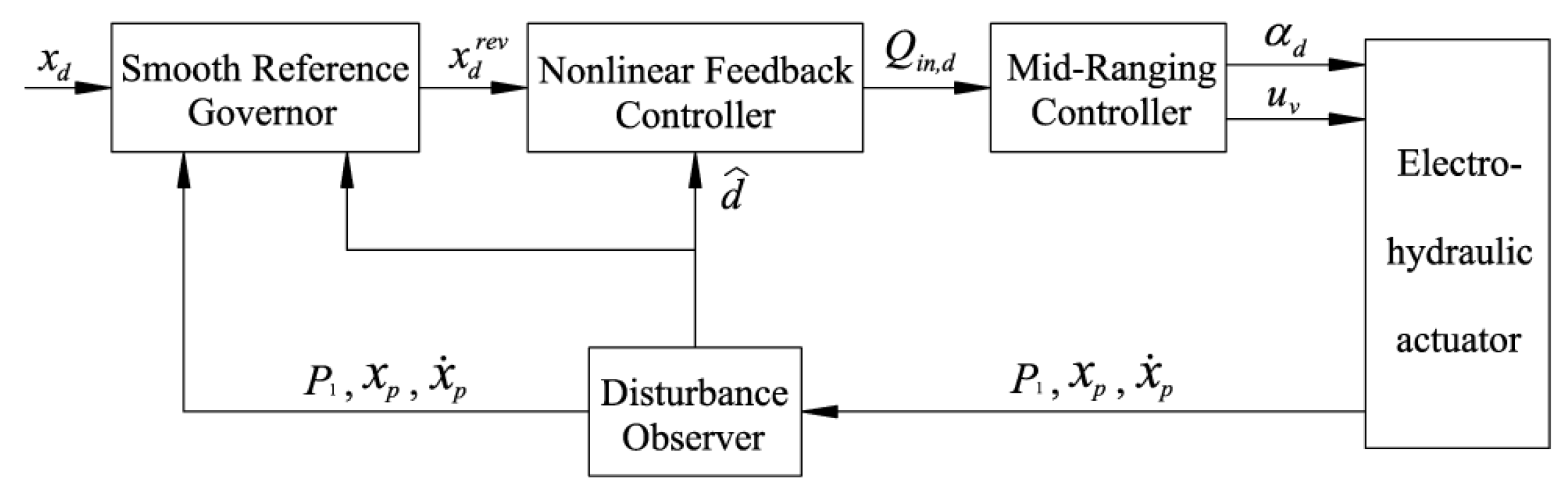
The proposed load pressure tracking controller can estimate the plant’s lumped disturbance caused by uncertain parameters to improve the robustness of the closed-loop system. In addition, a mid-range controller that dynamically allocates the command to the pump and proportional valve is used, which can make the best of the higher bandwidth of the proportional valve and keep the valve position close to the midpoint of its range.
(2)
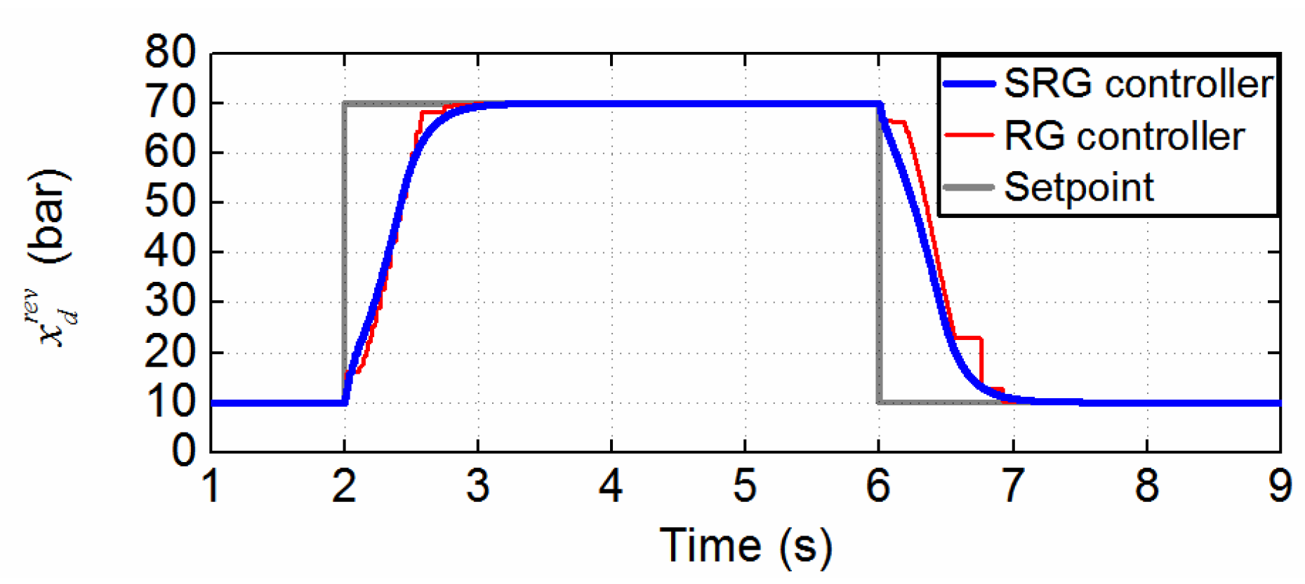
A novel reference governor is augmented to ensure that the rate and magnitude constraints of the pump and the valve are not violated. If constraint violation is foreseen, the pressure reference trajectory will be reduced. The proposed method can generate smoother pressure trajectories than nominal reference governors, and therefore, it will not excite high-frequency modes, which helps to improve the model accuracy used in the prediction.
The remaining sections are organized as follows. In Section 2, the mathematical model is presented. Section 3 describes the nonlinear controller, including the mid-range controller and the innovative smooth reference governor. In Section 4, a case study demonstrating the effectiveness of the proposed controller is presented. Finally, conclusions are drawn in Section 5.

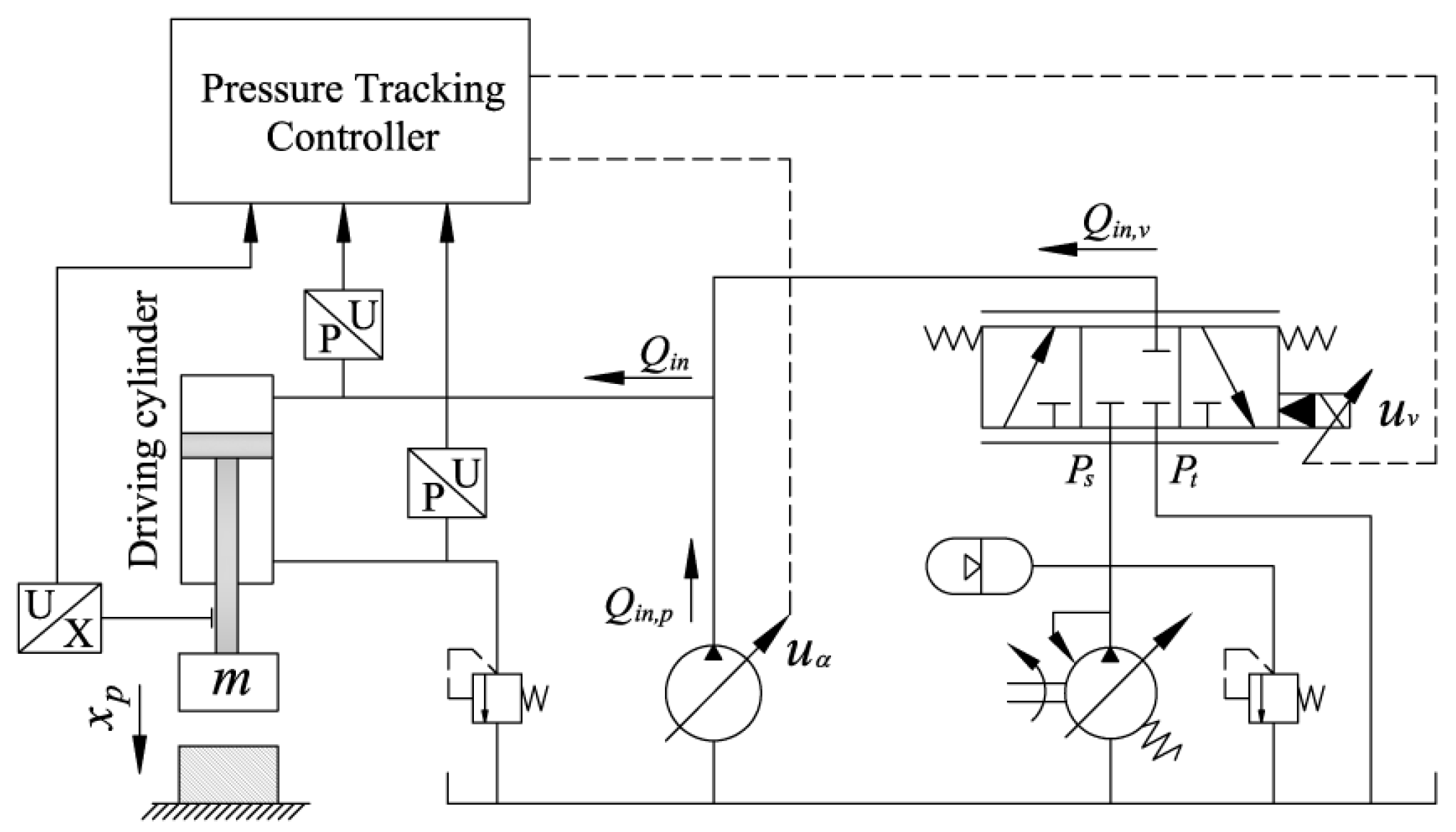
2. Mathematical Modeling

The analyzed system is depicted in Figure 1. The dynamics of the piston of the cylinder can be described by:
m x ¨ p = P 1 A 1 P 2 A 2 F l  
where m is the mass of the load, xp is the displacement of the cylinder, P1 and P2 are the pressures in the forward and return chambers of the cylinder, A1 is the piston area in the non-rod chamber, A2 is the piston area in the rod chamber, and the overall load force is denoted by Fl.
The dynamics of the cylinder’s pressure can be expressed as [33]:
V 01 + A 1 x p β e P ˙ 1 = Q i n A 1 x ˙ p C t ( P 1 P 2 )
where V01 and V02 are the total control volumes of the cylinder and the hoses connecting the cylinder to the valve, respectively, βe is the bulk modulus of oil, Ct is the internal leakage coefficient, and the flow rate Qin is given in [34] as the following equation:
Q i n = Q i n , p + Q i n , v = k p α + k q x v [ s g ( x v ) P s P 1 + s g ( x v ) P 1 P t ]
where Qin,p is the flow rate of the pump, and Qin,v is the flow rate of the valve.
We define the function
s g ( x ) = { 1 , if   x     0 0 , if   x   <   0
where the pump flow gain kp is a constant when the pump rotation speed is fixed, α is the swashplate angle, kq is the flow gain of the servo valve, xv is the valve spool displacement, Ps is the discharge pressure of the pump, and Pt is the tank pressure.
In this paper, the swashplate angle dynamics is modeled using second-order dynamic systems, and the pump swashplate angle’s magnitude and rate limitations are considered. The angle dynamics is given as
α ¨ = 2 ξ α ω α [ S R ( ω α 2 2 ξ α ω α ( S M ( u α ) α ) ) α ˙ ]
where uα is the swashplate angle, ωα and ξα represent the natural frequency and damping ratio of the system, and SM(∙) and SR(∙) are constraints on the magnitude and the rate. They are defined by:
S M ( x ) = { M x M if if if x M | x | < M x M
The transfer function, defined as the relationship between the input uα and the swashplate angle α, is expressed as
α ( s ) u α ( s ) = ω α 2 s 2 + 2 ξ α ω α s + ω α 2
The proportional valve dynamics can be modeled as:
x ¨ v = 2 ξ v ω v [ S R ( ω v 2 2 ξ v ω v ( S M ( k x u v ) x v ) ) x v ]
where uv is the input command, and ωv and ξv represent the natural frequency and damping ratio of the valve.
We define x = [ x 1 , x 2 , x 3 , x 4 , x 5 , x 6 , x 7 ] T = [ x p , x ˙ p , P 1 , α , α ˙ , x v , x ˙ v ] T . The system is expressed as
x ˙ 1 = x 2 x ˙ 2 = 1 m [ A 1 x 3 A 2 P 2 F l ] x ˙ 3 = h ( x 1 ) [ A 1 x 2 C t ( x 3 P 2 ) + Q i n ( x 3 , x 4 , x 6 ) ] x ˙ 4 = x 5 x ˙ 5 = 2 ξ α ω α [ S R ( ω α 2 2 ξ α ω α ( S M ( u α ) x 4 ) ) x 5 ] x ˙ 6 = x 7 x ˙ 7 = 2 ξ v ω v [ S R ( ω v 2 2 ξ v ω v ( S M ( u v ) x 6 ) ) x 7 ]
with
h ( x 1 ) = β e A 1 x 1 + V 01 Q i n ( x 3 , x 4 , x 6 ) = k p x 4 + k q x 6 g ( x 3 , x 6 ) g ( x 3 , x 6 ) = s g ( x 6 ) P s x 3 + s g ( x 6 ) x 3 P t
The nonlinear model shown (9) is a high-order, i.e., seventh-order, model, which makes it hard to use this form to synthesize a model-based control strategy. In order to make the controller design much more intuitive, model in (9) should be simplified as follows [26]:
x ˙ = h ( x p ) [ A 1 x ˙ p d + Q i n ( x , x v , α ) ] h ( x p ) = β e A 1 x p + V 01 Q i n ( x , x v , α ) = Q i n , p + Q i n , v = k p α + k q x v g ( x , x v )
A mid-range controller was designed to allocate Qin between Qin,p and Qin,v, making use of the proportional valve’s higher bandwidth while retaining the proportional valve’s location near the middle of its operating range so as not to violate its limit. For the considered system, many parameters are unknown or uncertain, and some are even continuously changing: e.g., the internal leakage coefficient varies with the oil temperature and cylinder rod position, and the bulk modulus of oil is based on oil pressure and air entrainment. Furthermore, accurate parameter estimation is very difficult; therefore, the parameter uncertainties and external disturbances are lumped into the term d.

3. Controller Design

3.1. Disturbance Observer

The proposed disturbance observer is used to estimate the disturbance d, which is given by:
x ^ ˙ = h ( x p ) ( A 1 x ˙ p + Q i n , d + d ^ ) + k 1 x ˜ o d ^ ˙ = k 2 x ˜ o
where x ^ and d ^ are the estimates of x and d, respectively, x ˜ o is the estimation error, Qin,d is the virtual control flow of the system, and k1 and k2 are control gains, respectively. The dynamics of x ˜ o can be given by:
x ˜ ˙ o = k 1 x ˜ o + h ( x p ) ( d ˜ + Q ˜ i n )
where Q ˜ i n is the control flow error, i.e., Q ˜ i n = Q i n Q i n , d .
Theorem 1.
According to the disturbance observer (12), if d is bounded, the disturbance estimation error  d ˜ is bounded and will converge exponentially to a sphere centered at the origin.
Proof. 
By combining (12) and (13), one obtains
[ x ˜ ˙ o d ˜ ˙ ] = [ k 1 h ( x p ) k 2 0 ] [ x ˜ o d ˜ ] + [ h ( x p ) Q ˜ i n d ˙ ]  
If k1 > 0 and k2 > 0, then the disturbance observer is stable. Furthermore, if the actuator constraints are respected, then Q ˜ i n is bounded; therefore, the disturbance estimation error d ˜ is bounded. □

3.2. Pressure Tracking Strategy

The nonlinear controller includes a disturbance observer-based pressure tracking controller to design the virtual control flow to the system.
The dynamics of the tracking error x ˜ c is given by:
x ˜ ˙ c = h ( x p ) [ A 1 x ˙ p d + Q i n ( x 1 , x v , α ) ] x ˙ d
A virtual controller Q i n , d for x ˜ c is designed as:
Q i n , d = A 1 x ˙ p d ^ c 1 a x ˜ c + 1 a x ˙ d
where c1 is the control gain.
As mentioned earlier, the proportional valve responds more quickly than the pump, but its stroke is limited. This paper introduces a mid-range controller for allocating the flow command between the valve and pump, utilizing the valve’s wider bandwidth while maintaining the spool position close to the middle of its functional range. Based on the respective frequency characteristics of the valve and pump, two filters, a high-pass filter H v for the valve and a low-pass filter H p for the pump, are introduced:
H p ( s ) = Q p , d Q i n , d = 2 ζ d a T d a s + 1 T d a 2 s 2 + 2 ζ d a T d a s + 1 H v ( s ) = Q v , d Q i n , d = T d a 2 s 2 T d a 2 s 2 + 2 ζ d a T d a s + 1
Therefore, we can obtain:
α ( s ) = H p ( s ) α p ( s ) + H v ( s ) α v ( s )
where α ( s ) , α p ( s ) and α v ( s ) are the transfer functions between the actual supply flow of the cylinder chamber and the virtual command flow, the real pump flow and the desired pump flow, and the actual valve flow and the ideal valve flow, respectively.
When in the low-frequency range, the pump and valve supply flow can easily track the desired flow, i.e., α p ( s ) 1 , α v ( s ) 1 , and we can obtain
α ( s ) H p ( s ) 1 + H v ( s ) 1 H p + H v = 1
Similarly, when in the high-frequency range, we can obtain
α ( s ) H p ( s ) 0 + H v ( s ) 1 H v ( s ) 1
Therefore, α ( s ) is approximately constant.
The variable displacement angle command is given as follows:
α d = Q p , d k p
From (10), the valve control voltage is given by
u v = { Q v , d k q k x P s x , if   Q v , d 0 Q v , d k q k x x P t , if   Q v , d < 0

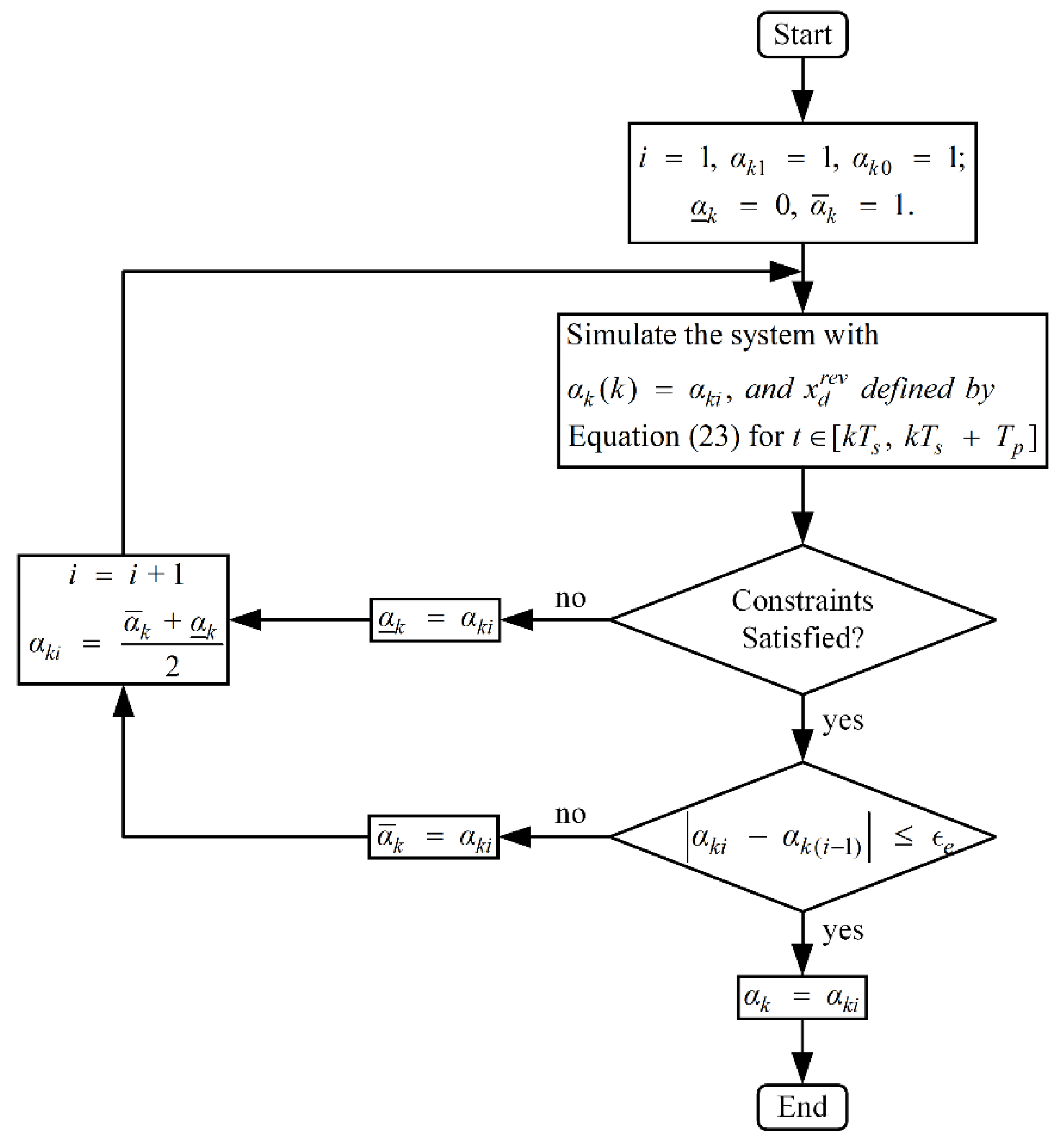
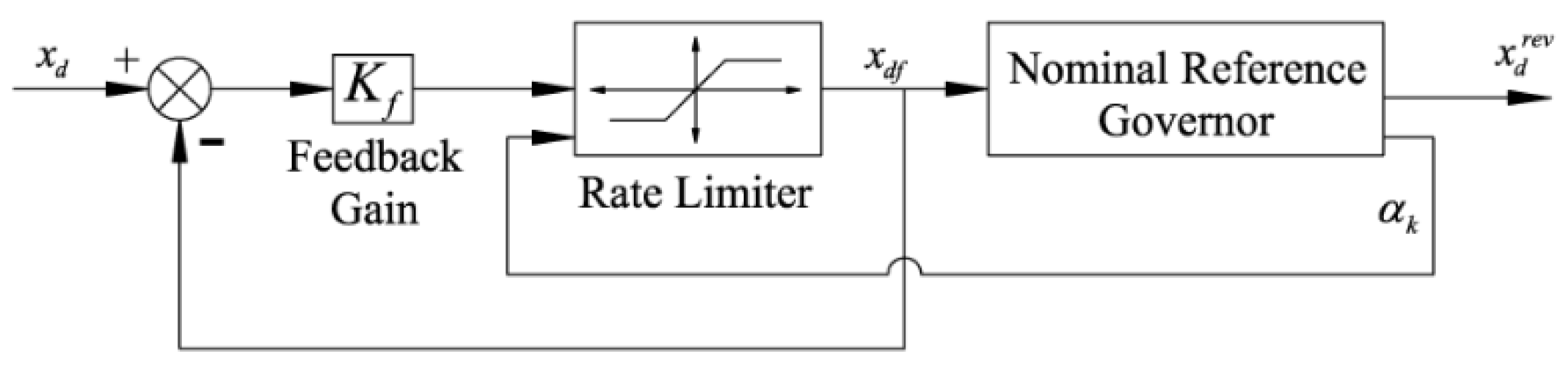
3.3. Nominal Reference Governor

As explained in Section 2, the valve displacement and pump angle are subject to magnitude and rate saturations. Once the system leaves its linear region, the boundedness of d ˜ will not be guaranteed, and the disturbance estimation d ^ will be corrupted due to actuator saturation. This problem can be alleviated by reducing the closed-loop system performance, i.e., by applying a filter to the pressure command. However, it cannot guarantee that the actuator saturation is eliminated. Another approach is to use model predictive control (MPC), which is able to exploit the entire actuator’s potential while respecting the actuator constraints, but the computational cost is high, especially for the nonlinear high-order system considered here.
In this paper, a reference governor is investigated to ensure that actuator limitations are not violated by the system. If a violation of constraints is anticipated, the trajectory will be modified until all constraints are satisfied. The receding horizon principle and the bisectional search algorithm are used here to check for constraint violations, as shown in Figure 2. The command xd is subjected to a bisectional search until the optimal modification is determined. This is implemented through the optimization of parameter α k :
x d r e v ( k ) = x d r e v ( k 1 ) + α k [ x d ( k ) x d r e v ( k 1 ) ]
where xd is the target trajectory, and x d r e v is the modified trajectory. When α k = 1 , the filter does not affect the input, and conversely, when α k = 0 , then x d r e v = x d r e v ( k 1 ) can be obtained. The optimal value of parameter α k is obtained during each time interval kTs by maintaining x d r e v ( τ ) = x d r e v ( k ) for k T s τ k T s + T p , where Tp is the prediction time horizon.
To determine α k at each time instant, the system in (11) including the controller dynamics in (16), (18), (21) and (22) are predicted over the interval [kTs, kTs + Tp]. α k is decreased if constraint violations are anticipated and raised if all constraints are met. The optimal value of α k [ 0 , 1 ] is subsequently determined. The constraints considered in this paper are as follows:
u v m i n u v u v m a x u α max u α u α m a x Δ u v m i n Δ u v Δ u v m a x Δ u α m i n Δ u α Δ u α m a x
where
Δ u v ( k ) = u v ( k ) u v ( k 1 ) Δ u α ( k ) = u α ( k ) u α ( k 1 )

3.4. Novel Smooth Reference Governor
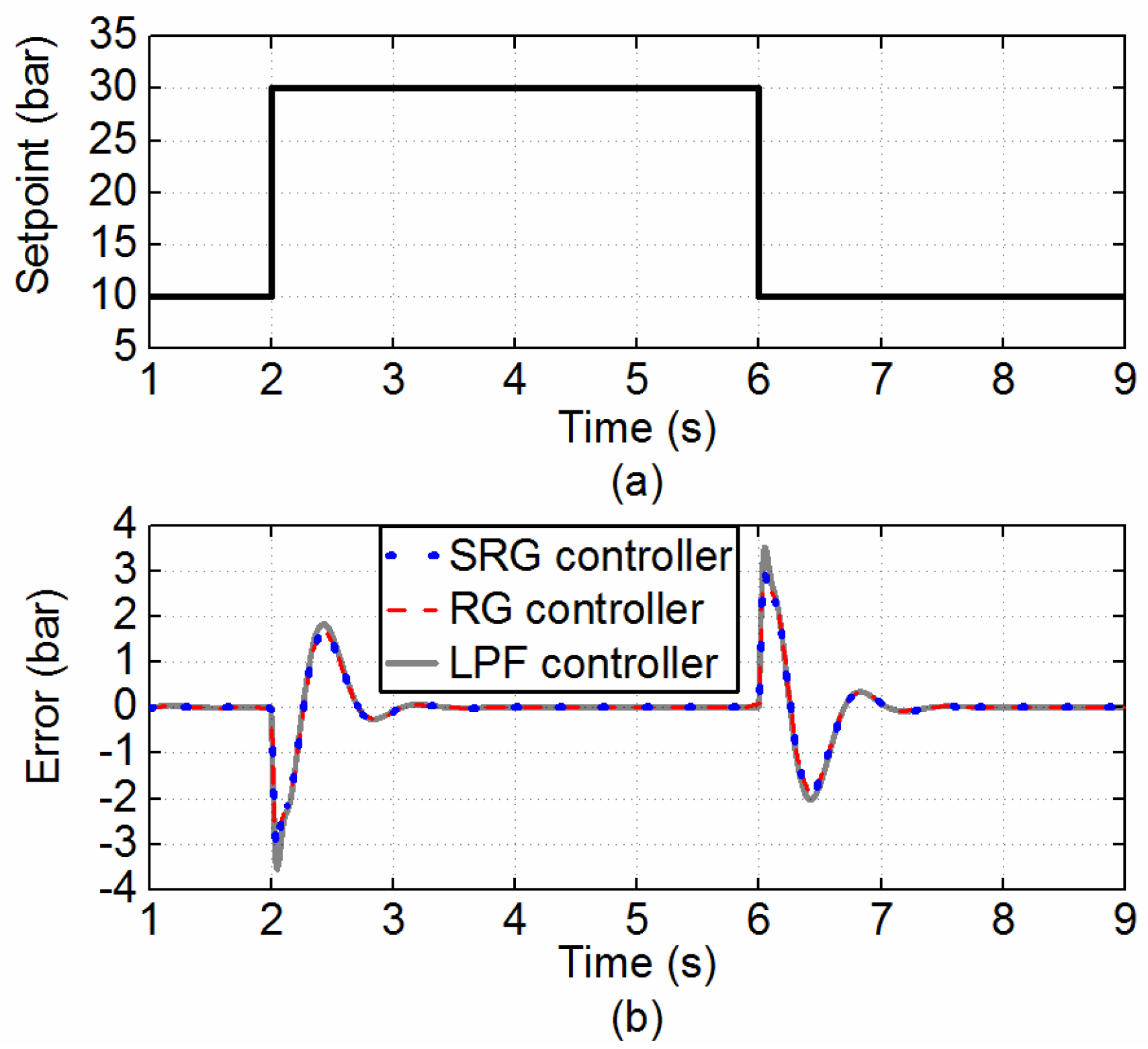
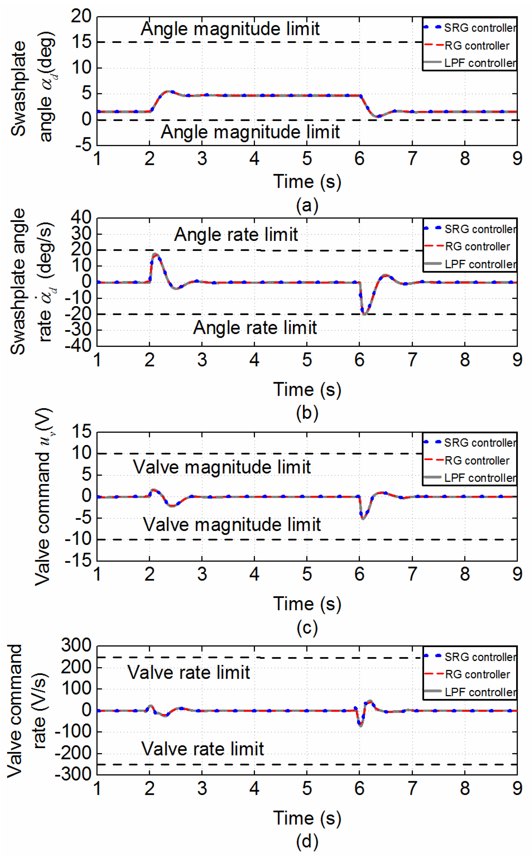
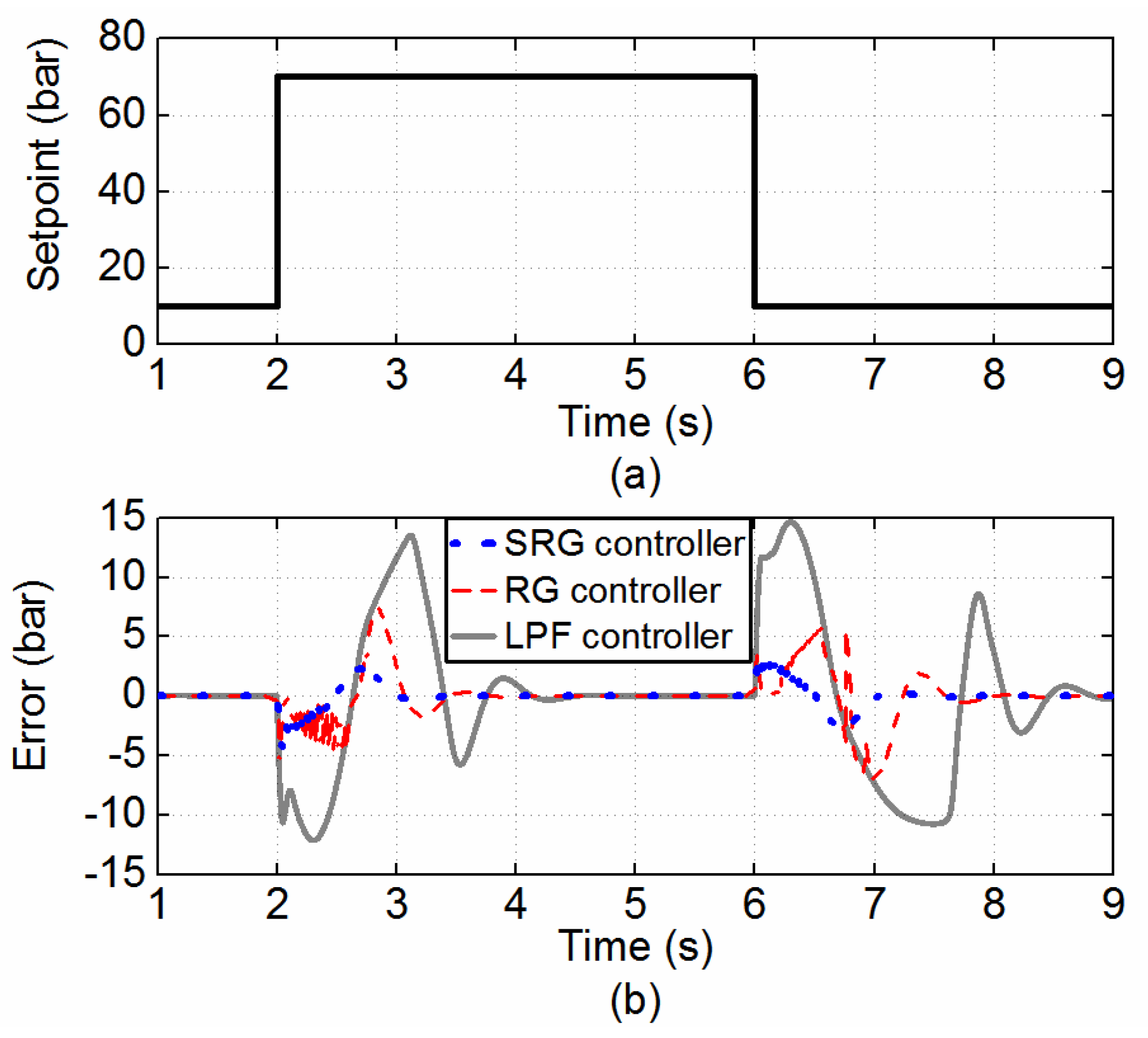
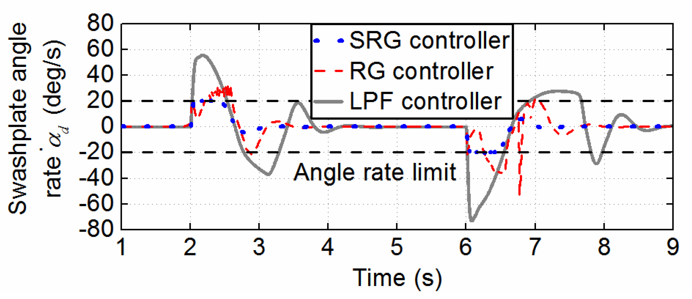
Despite the advantages of the nominal reference governor, the revised trajectory is discontinuous or even jitters if the trajectory xd changes rapidly [35]; therefore, when the discontinuous revised trajectory is applied to the closed-loop system, unmodeled high-frequency plant dynamics will be invoked, and the plant model used in the reference governor will not be accurate, which will decrease the plant behavior prediction accuracy. In this paper, a novel smooth reference governor is proposed to handle this problem, which can smooth the fast-changing trajectory by introducing a feedback mechanism based on the nominal reference governor; i.e., the nominal reference governor is augmented with a dynamic rate limiter, the threshold of which is closely related to α k . The feedback mechanism of the dynamic rate limiter is shown in Figure 3 and is given as:
x ˙ d f = S M f [ K f ( x d x d f ) ]
where xdf is the pressure trajectory used as the reference governor input, Kf is the feedback gain and SMf(∙) is the saturation function given by:
S M f ( x ) = { α k M f x α k M f if if if x α k M f | x | < α k M f x α k M f
where Mf is a constant.
The revised trajectory from the dynamic rate limiter xdf is then fed to the reference governor (23). If the actuator constraints are violated, then α k is decreased; as a result, the dynamic threshold of SMf(∙) is then decreased, and therefore, the change rate of xdf is slowed down, making xdf smoother than that of the nominal reference governor. The smooth trajectory helps prevent the unmodeled high-frequency dynamics from happening, which improves the plant model credibility in the model prediction. Therefore, the actuator constraint violation prediction accuracy is improved.
The block diagram of the proposed control structure is shown in Figure 4. As shown, the proposed smooth reference governor transforms the pressure xd to a revised reference signal x d r e v . The nonlinear feedback controller treats x d r e v as the command, and then a virtual flow command Q i n , d is generated. Finally, Q i n , d is divided into α d and u v by the mid-range controller, which drive the pump and valve, respectively.

4. Case Studies

In the case studies described in this section, the presented controller was applied to the electrohydraulic system of a hydraulic press, the maximum load of which is 700 kN. The dynamics of the system are defined by (9), and the system parameters of the hydraulic press are given in Table 1.
To show the efficiency of the suggested method, two case studies were carried out in a simulation, and the following three controllers were compared in the two cases:
(1)
The proposed smooth reference governor-based controller (SRG);
(2)
The nominal reference governor-based controller (RG);
(3)
A third controller conducting pressure tracking without a reference governor. The impact of the reference governor was simulated by a first-order low-pass filter (LPF) with a 0.17 s time constant.
The selection of the control parameters of the proposed controller is based on the following rules: (1) control gains k1, k2 and c1 are chosen based on the saturation limits and bandwidth of the actuator; (2) filter parameters Tda and ξda depend on the saturation value of the valve displacement; and (3) decreasing the sampling time Ts and increasing the prediction time Tp can improve control performance, but more computing resources are required. According to the above rules and through trial and error, the control parameters of the proposed SRG controller were chosen for the simulation, as shown in Table 2.
Case 1: Mild Pressure Trajectory Test.
The three controllers were first tested with the trajectory shown in Figure 5. The constraints for the pump and valve were satisfied for all three controllers, and these three controllers showed almost the same performance, which can be seen in Figure 6. This is due to the relatively mild pressure trajectory, which can be tracked without aggressive actuator control. It also shows that the proposed smooth reference governor does not slow down the tracking results when the actuator constraints are not violated.
Case 2: Violent Pressure Trajectory Test
Figure 7 shows the performance when a step trajectory from 10 bar to 70 bar is used. The variable displacement pump’s angle rate constraint is strongly violated, leading to oscillating tracking performance if no load governor is used. Compared with the smooth reference governor, the nominal reference governor applies the pressure trajectory too aggressively, which leads to intermediate steps when α k cannot be optimized. This results in the jittering trajectory shown in Figure 8. In addition, the constraints are slightly violated compared with the novel reference governor, as shown in Figure 9. The smooth reference governor avoids intermediate infeasible steps, and the updated trajectory is smooth and satisfies all constraints. This is due to the novel feedback mechanism inherent in the smooth reference governor, which dynamically slows down the trajectory according to α k ; this helps to avoid exciting the unexpected high-frequency dynamics of the system and helps to improve the model prediction accuracy.

5. Conclusions

In this paper, a DOB-based load pressure control strategy with a novel smooth reference governor is proposed for dual-actuator-driven electrohydraulic cylinders. The DOB-based feedback controller and mid-range control architecture can suppress the performance degradation caused by the pump’s slow responses and imprecise system parameters. In addition, the novel smooth reference governor ensures a smooth trajectory and will not excite the unwanted high-frequency dynamics of the plant. The results of case studies show that the novel feedback mechanism of the smooth reference governor can dynamically slow down the trajectory and avoid exciting the unexpected high-frequency dynamics of the system, which helps to improve model prediction accuracy. The benefits of the novel smooth reference generator are verified by the superior tracking performance of the hydraulic system.

Author Contributions

Conceptualization, G.Z., S.C., Y.L. and K.G.; data curation, G.Z.; formal analysis, G.Z., S.C., Y.L. and K.G.; funding acquisition, Y.L. and K.G.; investigation, G.Z., S.C., Y.L. and K.G.; methodology, G.Z., S.C., Y.L. and K.G.; project administration, Y.L.; resources, Y.L.; software, Y.L.; supervision, K.G.; validation, S.C.; visualization, G.Z.; writing—original draft, G.Z., S.C., Y.L. and K.G.; writing—review and editing, G.Z., S.C., Y.L. and K.G. All authors have read and agreed to the published version of the manuscript.

Funding

This research was funded by the Key R&D Program of Shandong Province under Grant 2019GGX104008 and Grant 2019JZZY020318.

Institutional Review Board Statement

Not applicable.

Informed Consent Statement

Not applicable.

Data Availability Statement

Not applicable.

Conflicts of Interest

The authors declare no conflict of interest.

References

  1. Feng, L.; Yan, H. Nonlinear Adaptive Robust Control of the Electro-Hydraulic Servo System. Appl. Sci. 2020, 10, 4494. [Google Scholar] [CrossRef]
  2. Nguyen, M.H.; Dao, H.V.; Ahn, K.K. Adaptive Robust Position Control of Electro-Hydraulic Servo Systems with Large Uncertainties and Disturbances. Appl. Sci. 2022, 12, 794. [Google Scholar] [CrossRef]
  3. Lin, S.; An, G.; Huang, J.; Guo, Y. Robust Backstepping Control with Active Damping Strategy for Separating-Metering Electro-Hydraulic System. Appl. Sci. 2020, 10, 277. [Google Scholar] [CrossRef] [Green Version]
  4. Guo, K.; Wei, J.; Tian, Q. Nonlinear adaptive position tracking of an electro-hydraulic actuator. Proc. Inst. Mech. Eng. Part C J. Mech. Eng. Sci. 2015, 229, 3252–3265. [Google Scholar] [CrossRef]
  5. Feng, H.; Qiao, W.; Yin, C.; Yu, H.; Cao, D. Identification and compensation of non-linear friction for a electro-hydraulic system. Mech. Mach. Theory 2019, 141, 1–13. [Google Scholar] [CrossRef]
  6. Guo, K.; Li, M.; Shi, W.; Pan, Y. Adaptive Tracking Control of Hydraulic Systems with Improved Parameter Convergence. IEEE Trans. Ind. Electron. 2022, 69, 7140–7150. [Google Scholar] [CrossRef]
  7. Ding, R.; Cheng, M.; Jiang, L.; Hu, G. Active Fault-Tolerant Control for Electro-Hydraulic Systems with an Independent Metering Valve Against Valve Faults. IEEE Trans. Ind. Electron. 2021, 68, 7221–7232. [Google Scholar] [CrossRef]
  8. Li, Z.; Wang, C.; Quan, L.; Hao, Y.; Ge, L.; Xia, L. Study on energy efficiency characteristics of the heavy-duty manipulator driven by electro-hydraulic hybrid active-passive system. Automat. Constr. 2021, 125, 103646. [Google Scholar] [CrossRef]
  9. Jing, C.; Xu, H.; Jiang, J. Practical torque tracking control of electro-hydraulic load simulator using singular perturbation theory. ISA Trans. 2020, 102, 304–313. [Google Scholar] [CrossRef]
  10. Du, H.; Shi, J.; Chen, J.; Zhang, Z.; Feng, X. High-gain observer-based integral sliding mode tracking control for heavy vehicle electro-hydraulic servo steering systems. Mechatronics 2021, 74, 102484. [Google Scholar] [CrossRef]
  11. Wang, C.; Jiao, Z.; Wu, S.; Shang, Y. Nonlinear adaptive torque control of electro-hydraulic load system with external active motion disturbance. Mechatronics 2014, 24, 32–40. [Google Scholar] [CrossRef]
  12. Lin, C.; Shen, F.; Wu, K.; Lee, H.; Hwang, S. Injection Molding Process Control of Servo–Hydraulic System. Appl. Sci. 2020, 10, 71. [Google Scholar] [CrossRef] [Green Version]
  13. Hua, Z.; Rong, X.; Li, Y.; Chai, H.; Li, B.; Zhang, S. Analysis and Verification on Energy Consumption of the Quadruped Robot with Passive Compliant Hydraulic Servo Actuator. Appl. Sci. 2020, 10, 340. [Google Scholar] [CrossRef] [Green Version]
  14. Chen, X.; Zheng, F.; Gan, W.; Xing, S. Exploration and Research on Key Technologies for Improving the Response Speed of Servo-Hydraulic Cylinders. Appl. Sci. 2022, 12, 4162. [Google Scholar] [CrossRef]
  15. Sidhom, L.; Chihi, I.; Smaoui, M. Automation of a Hybrid Control for Electrohydraulic Servo-Actuators with Residual Dynamics. Appl. Sci. 2022, 12, 2856. [Google Scholar] [CrossRef]
  16. Wei, J.; Guo, K.; Fang, J.; Tian, Q. Nonlinear supply pressure control for a variable displacement axial piston pump. Proc. Inst. Mech. Eng. Part I J. Syst. Control Eng. 2015, 229, 614–624. [Google Scholar] [CrossRef]
  17. Ge, L.; Dong, Z.; Huang, W.; Quan, L.; Yang, J.; Li, W. Research on the Performance of Hydraulic Excavator with Pump and Valve Combined Separate Meter in and Meter out Circuits. In Proceedings of the 2015 international conference on fluid power and mechatronics (FPM), Harbin, China, 5–7 August 2015. [Google Scholar]
  18. Tunay, I.; Rodin, E.Y.; Beck, A.A. Modeling and robust control design for aircraft brake hydraulics. IEEE Trans. Contr. Syst. Trans. 2001, 9, 319–329. [Google Scholar] [CrossRef]
  19. Hongliu, D. Pressure Control with Power Limitation for Hydraulic Variable Displacement Piston Pumps Hongliu Du. In Proceedings of the 2002 American Control, Anchorage, AK, USA, 8–10 May 2002; pp. 940–945. [Google Scholar]
  20. Parker, N.R.; Salcudean, S.E.; Lawrence, P.D. Application of Force Feedback to Heavy Duty Hydraulic Machines. In Proceedings of the [1993] Proceedings IEEE International Conference on Robotics and Automation, Atlanta, GA, USA, 2–6 May 1993. [Google Scholar]
  21. Zhu, C.; Zhang, H.; Wang, W.; Li, K.; Zhou, Z.; He, H. Compound Control on Constant Synchronous Output of Double Pump-Double Valve-Controlled Motor System. Processes 2022, 10, 528. [Google Scholar] [CrossRef]
  22. Yu, B.; Zhu, Q.; Yao, J.; Zhang, J.; Huang, Z.; Jin, Z.; Wang, X. Design, Mathematical Modeling and Force Control for Electro-Hydraulic Servo System with Pump-Valve Compound Drive. IEEE Access 2020, 8, 171988–172005. [Google Scholar] [CrossRef]
  23. An, G.; Peng, Z.; Fu, Y. The Application of Predictive Functional Control to New Motor Pump-Valve Compound Control System. In Proceedings of the 2009 9th International Conference on Electronic Measurement & Instruments, Beijing, China, 16–19 August 2009. [Google Scholar]
  24. Ding, H.; Zhao, J.; Cao, C.; Zhao, L. Valve–pump parallel variable mode control for hydraulic speed regulation of high-power systems. Adv. Mech. Eng. 2017, 9, 2071941856. [Google Scholar] [CrossRef]
  25. Ding, H.; Zhao, J. Performance analysis of variable speed hydraulic systems with large power in valve-pump parallel variable structure control. J. Vibroeng. 2014, 16, 1042–1062. [Google Scholar]
  26. Komsta, J.; van Oijen, N.; Antoszkiewicz, P. Integral sliding mode compensator for load pressure control of die-cushion cylinder drive. Control Eng. Pract. 2013, 21, 708–718. [Google Scholar] [CrossRef]
  27. Guo, K.; Wei, J.; Fang, J.; Feng, R.; Wang, X. Position tracking control of electro-hydraulic single-rod actuator based on an extended disturbance observer. Mechatronics 2015, 27, 47–56. [Google Scholar] [CrossRef]
  28. Tian, Q.; Wei, J.; Fang, J.; Guo, K. Adaptive fuzzy integral sliding mode velocity control for the cutting system of a trench cutter. Front. Inf. Technol. Electron. Eng. 2016, 17, 55–66. [Google Scholar] [CrossRef]
  29. Komsta, J.; Adamy, J.; Antoszkiewicz, P. Input-Output Linearization and Integral Sliding Mode Disturbance Compensation for Electro-hydraulic Drives. In Proceedings of the 2010 11th International Workshop on Variable Structure Systems (VSS), Mexico City, Mexico, 26–28 June 2010. [Google Scholar]
  30. Liu, S.; Yao, B. Automated onboard modeling of cartridge valve flow mapping. IEEE/ASME Trans. Mechatron. 2006, 11, 381–388. [Google Scholar]
  31. Kemmetmüller, W.; Fuchshumer, F.; Kugi, A. Nonlinear pressure control of self-supplied variable displacement axial piston pumps. Control Eng. Pract. 2010, 18, 84–93. [Google Scholar] [CrossRef]
  32. Yun, J.N.; Su, J. Design of a Disturbance Observer for a Two-Link Manipulator with Flexible Joints. IEEE Trans. Contr. Syst. Trans. 2014, 22, 809–815. [Google Scholar] [CrossRef]
  33. Merritt, H.E. Hydraulic Control Systems; Wiley: Hoboken, NJ, USA, 1967. [Google Scholar]
  34. Guo, K.; Wei, J. Adaptive Robust Control of Variable Displacement Pumps. In Proceedings of the 2013 American Control Conference, Washington, DC, USA, 17–19 June 2013. [Google Scholar]
  35. Sun, J.; Kolmanovsky, I.V. Load governor for fuel cell oxygen starvation protection: A robust nonlinear reference governor approach. IEEE Trans. Contr. Syst. Trans. 2005, 13, 911–920. [Google Scholar]
Figure 1. Schematic diagram of the hydraulic system.
Applsci 12 08367 g001
Figure 2. Bisectional search algorithm to optimize αk.
Applsci 12 08367 g002
Figure 3. The schematic diagram of the smooth reference governor.
Applsci 12 08367 g003
Figure 4. Block diagram of the controller structure.
Applsci 12 08367 g004
Figure 5. Tracking performance for a step trajectory from 10 bar to 30 bar. (a) The pressure trajectory. (b) The tracking error of the three controllers.
Applsci 12 08367 g005
Figure 6. Actuator control inputs of the three controllers for a step trajectory from 10 bar to 30 bar. (a) The swashplate angle. (b) The swashplate angle rate. (c) The valve command. (d) The valve command rate.
Applsci 12 08367 g006
Figure 7. Tracking performance for a step trajectory from 10 bar to 70 bar. (a) The pressure trajectory. (b) The tracking error of the three controllers.
Applsci 12 08367 g007
Figure 8. Trajectory used for the nonlinear DOB controller of the three controllers.
Applsci 12 08367 g008
Figure 9. Actuator control inputs of the three controllers for a step trajectory from 10 bar to 70 bar.
Applsci 12 08367 g009
Table 1. Parameters of the electrohydraulic system.
ParameterDescriptionValue
mLoad mass1200 kg
A1Driving cylinder piston side chamber area3.8 × 10−2 m2
PsPump supply pressure2.0 × 107 Pa
CtDriving cylinder leakage coefficient0 m3/(s∙Pa)
βeOil bulk modulus1 × 109 Pa
kq∙kxServo valve flow gain coefficient 1.782   ×   10 8   m 3 / ( s · V · Pa )
kpPump flow coefficient6.56 × 103 m3/(s∙rad)
ωαPump dynamics natural frequency25 rad/s
ξαPump dynamics damping ratio 1
ωvValve dynamics natural frequency200 rad/s
ξvValve dynamics damping ratio 1
Table 2. Parameters of the controller.
ParameterValueParameterValue
k1200k25.43 × 108
c110Tda0.15
ξda1Ts0.001
Tp0.3
Publisher’s Note: MDPI stays neutral with regard to jurisdictional claims in published maps and institutional affiliations.

